


289 SERIES
FLOW METER TRANSMITTERS

INSTRUCTION MANUAL
289 SERIES TRANSMITTER
289-763 Pickup Coil/Amplifier, Amphenol Connector
289-773 Pickup Coil/Amplifier, Weather-Tight, Explosion-Proof*
TABLE OF CONTENTS
General Description . . . . . . . . . . . . . . . . . . . . . . . . . . . .Pg 2
Specifications . . . . . . . . . . . . . . . . . . . . . . . . . . . . . . . . .Pg 3
Installation . . . . . . . . . . . . . . . . . . . . . . . . . . . . . . . . . . .Pg 4
User Options & Adjustments . . . . . . . . . . . . . . . . . . . . .Pg 5
Maximum Transmission Distance . . . . . . . . . . . . . . . . . .Pg 6-7
Typical K-Factors . . . . . . . . . . . . . . . . . . . . . . . . . . . . . .Pg 8
Schematics . . . . . . . . . . . . . . . . . . . . . . . . . . . . . . . . . . .Pg 9
*U.L.Class I, Group C & D
Class II, Group E, F & G
289-760-350 © 1987 (Rev 5/06), Max Machinery, Inc.
Max Machinery, Inc. reserves the right to make changes to the product in this Instruction
Manual to improve performance, reliability, or manufacturability. Consequently, contact
MMI for the latest available specifications and performance data.
Although every effort has been made to ensure accuracy of the information contained in
this Instruction Manual, MMI assumes no responsibility for inadvertent errors.

289-760-350 © 1987 (Rev 5/06) Max Machinery, Inc. ( 2 )
The 289 Series Transmitter has an inductive pickup which senses the motion of an internal
flow meter gear. As the tooth of a gear moves under the core of the pickup, a voltage is
induced in a coil wound around the core. The gear is fastened to the rotor shaft of the 240
Series meter, which allows its rotational rate to be directly proportional to the flow rate.
The output of the pickup coil is amplified and squared before being sent to the output
terminals. The resulting pulse train is relatively insensitive to interference and can be
transmitted as far as generally required.
General Description

( 3 ) 289-760-350 © 1987 (Rev 5/06) Max Machinery, Inc.
Specifications
289-763/773 5V Square Wave Output:
Power Requirements:
Voltage (5V regulator on PCA) . . . . . . . . . . . . . . . . . . . . .5-24VDC
Nominal (3.5-30V Max)
Current (No Load)
Supply Voltage Operating Calibrating
3.5V 1.1mA 1.6mA
5.0 - 24.0V 1.8mA 3.0mA
Output Signal
Shape . . . . . . . . . . . . . . . . . . . . . . . . . . . . . . . . . . . . . .Square Wave
Amplitude . . . . . . . . . . . . . . . . . . . . . . . . . . . . . . . . . . . . . . . . . .5V
Rise and Fall Time . . . . . . . . . . . . . . . . . . . . . . . . . . . . . . . . . . .3µS
Output Impedance . . . . . . . . . . . . . . . . . . . . . . . . . . . . . .<200ohms
Maximum Frequency . . . . . . . . . . . . . . . . . . . . . . . . . . . . . . . .5kHz
Minimum Frequency . . . . . . . . . . . . . . . . . . . . . . . . . . . . . . .1/50Hz
Output vs Load: (Supply > 5.2V)
Load mA Output Low Output Hi
0.1mA 0V 5.00V
1.0mA 0V 4.85V
5.0mA 0V 4.25V
10.0mA 0V 3.45V
Temperature Limits (All Models):
Operating
Electronics . . . . . . . . . . . . . . . . . . . . . . . . . .-5 to 150F (-20 to 65C)
Pickup Coil . . . . . . . . . . . . . . . . . . . . .-148 to 450F (-100 to 232C)
Storage
Electronics . . . . . . . . . . . . . . . . . . . . . . . . .-40 to 175F (-40 to 80C)
Pickup Coil . . . . . . . . . . . . . . . . . . . . .-148 to 450F (-100 to 232C)

289-760-350 © 1987 (Rev 5/06) Max Machinery, Inc. ( 4 )
Installation
Mounting: The Model 289 transmitter screws on and off of the flow meter. Because of the
random location of the starting point of the threads, one transmitter will probably not line up
with the "in" and "out" ports of the flow meter like another will. The electrical outlet of the
transmitter can be rotated one turn by loosening the clamping screw. (See drawing, page 2)
Moisture Protection: The electrical circuitry of the weather-tight, explosion proof transmitter
is enclosed in a liquid and vapor tight enclosure. All joints are sealed by welding or by "O"rings. If this sealed condition is to be maintained, the conduit connection to the enclosure
should be made liquid and vapor tight by using pipe dope or a potting fitting (U.L. requires a
potting fitting within 18" of the transmitter.). If a transmitter is located outside and this
precaution is not taken, moisture may form inside the housing. This will cause the circuitry to
give an inaccurate output or possibly no output at all. In the long run it will cause corrosion
and failure. The amphenol connector versions of the 289 Series Transmitter offer moderate
protection from moisture and dust but are not totally sealed.
Temperature Considerations: High ambient temperatures (120°F/50°C) should be avoided if
possible. It is a good idea to locate the transmitter away from hot spots such as steam pipes,
ovens and heaters. The electronics of the 289 Series Transmitters are rated for operation up to
65°C or 150°F. Because some heat travels from the flow meter to the transmitter
electrical enclosure, the temperature the electronics see is a function of both the ambient
and the flow meter temperature. The graph below shows the relationship between the
maximum ambient transmitter temperature and the fluid temperature through the flow meter.
The pickup coil of the 289 Series Transmitter is insulated with an epoxy that is rated to
232°C/450°F. This is the maximum flow meter fluid temperature.

( 5 ) 289-760-350 © 1987 (Rev 5/06) Max Machinery, Inc.
User Options & Adjustments
289-763/773 TRANSMITTER
Grounding: S2-l connects Common and Case directly together. S2-2 connects Common and
Case through 4.7 µF capacitors. By using either switch the effects of electrical noise on the
transmitter can be reduced. If the system is not grounded at the indicator or if the flow meter
is not physically grounded through its plumbing, use S2-l. If the system is grounded at the
indicator, use S2-2. This allows electrical noise between the case and the circuitry of the
transmitter to be reduced without causing ground loop problems. To activate either switch,
depress the side of the switch that is numbered.
Sensitivity Adjustment R2, S1, LED: For best results, the transmitter amplifier sensitivity
should be adjusted to match the output voltage of the particular pickup and flow meter it is
mated to. This is typically factory calibrated, but should be checked if the coil or circuit board
is changed or if the transmitter is switched from one flow meter to another.
To adjust the sensitivity, set the flow rate through the flow meter to approximately midrange.
Press the Sensitivity Adjustment Switch (S1): One or both sides of the LED should come on.
Turn the Sensitivity pot (R2) FCW then turn it CCW just until both sides of the LED show
equal brightness or are on for about equal periods of time (if the frequency is low).
Outputs: The Model 289 transmitter output is generally sent to a signal conditioner display
such as the Max 120, which provides signal dampening, scaling, and rate/total displays; as
well as supplying power to the transmitter. A complete line of LCD display instrumentation is
also available from MAX for flow rate, total, batching, and flow control .
S1 Sensitivity
Adjust Switch
Coil Connectors
R2 Sensitivity Adjust
Amphenol Pinout (Optional)
A = Ground
B = Common
C = 5 to 24VDC
D = Square Wave Output
E = No Connection
F = No Connection
Sensitivity Adjust LED
Amphenol
Connection Option
Signal (White) (D)
Power (Red) (C)
Common (Black) (B)
Ground (Green) (A)
S2-1 Ground
S2-2 Filter

289-760-350 © 1987 (Rev 5/06) Max Machinery, Inc. ( 6 )
Maximum Transmission Distance
MAXIMUM TRANSMISSION DISTANCE
The graph below shows typical conductor capacitance load vs. cable length for several types
of cable. For instance, 1,000 ft. of 7 conductor #18 gauge stranded wire will put a 0.04 µF
capacitive load on the output of the Model 289 transmitter.
( 7 ) 289-760-350 © 1987 (Rev 5/06) Max Machinery, Inc.
Maximum Transmission Distance
MAXIMUM TRANSMISSION DISTANCE
(continued)
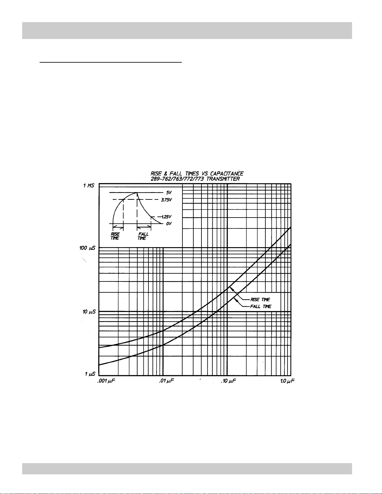
The graph below provides the relationship between output capacitance loading and rise and
fall time for the Model 289-763/773 output signal. For instance, with 0.4 µF the rise time of
the Model 289 is about 89 µS, and the fall time about 45 µS. Consequently, the absolute
maximum frequency the 289 could put out would be 1/(80 + 45) µS = 8000 Hz (frequency =
1/time). The signal would be a saw tooth pattern. Generally, the transmitter will drive 5000
feet or more of cable with no problem.

289-760-350 © 1987 (Rev 5/06) Max Machinery, Inc. ( 8 )
Typical K-Factors / Typical Connections
Typical K-Factors for 240 Series Flow Meters using the 289 Series Transmitter
241 Flow Meter (.062 Liter/Rev)
Pulses/Liter . . . . . . . . . . . . . . . . . . . . . . . . . . . . . . . . . . . . . . . . . . . . . . .403
Maximum Rate . . . . . . . . . . . . . . . . . . . . . . . . . . . . . . . . . . . . . . .190 L/min
242 Flow Meter (.182 Liter/Rev)
Pulses/Liter . . . . . . . . . . . . . . . . . . . . . . . . . . . . . . . . . . . . . . . . . . . . . . .219
Maximum Rate:
SS Rotors . . . . . . . . . . . . . . . . . . . . . . . . . . . . . . . . . . . . . . . . .450 L/min
AL Rotors . . . . . . . . . . . . . . . . . . . . . . . . . . . . . . . . . . . . . . . . .540 L/min
243 Flow Meter (.574 Liter/Rev)
Pulses/Liter . . . . . . . . . . . . . . . . . . . . . . . . . . . . . . . . . . . . . . . . . . . . . . .104
Maximum Rate:
SS Rotors . . . . . . . . . . . . . . . . . . . . . . . . . . . . . . . . . . . . . . . .1000 L/min
AL Rotors . . . . . . . . . . . . . . . . . . . . . . . . . . . . . . . . . . . . . . . .1400 L/min
244 Flow Meter (1.70 Liter/Rev)
Pulses/Liter . . . . . . . . . . . . . . . . . . . . . . . . . . . . . . . . . . . . . . . . . . . . . . .58.8
Maximum Rate:
SS Rotors . . . . . . . . . . . . . . . . . . . . . . . . . . . . . . . . . . . . . . . .2400 L/min
AL Rotors . . . . . . . . . . . . . . . . . . . . . . . . . . . . . . . . . . . . . . . .3500 L/min

 Loading...