

Page 1
an ISO 9001:2008 certified company
Linearized
Analog Transmitters
Operational Manual
For Models
295, 296 and G Series Transmitters
Page 2

Table of Contents
General description ............................................................... 3
Transmitter specications ...................................................4
Installation - Models 295, 296 ............................................ 5
Electrical installation, wiring ............................................... 5
High temperature operation ............................................... 6
Temperature limits chart Models 295, 296 ..................... 7
Hazardous location installation .................................... 8-10
Electrical installation ...........................................................10
Electrical requirements .......................................................10
Temperature classication .................................................10
Declaration of conformity .................................................... 11
Additional technical documents regarding transmitter performance and advanced operation are available
at www.maxmachinery.com. Max Machinery, Inc. reserves the right to make changes to the product in this
instruction manual to improve performance, reliability, or manufacturability. Contact Max Machinery Inc. for
the latest available specications and performance data. Although every effort has been made to ensure
accuracy of the information in this instruction manual, Max Machinery Inc. assumes no responsibility for
inadvertent errors.
IH 295-200-350 • rev. 6/2011 • ©2010-11 Max Machinery, Inc.
2
Page 3
General Description
These Max transmitters are designed to work with the
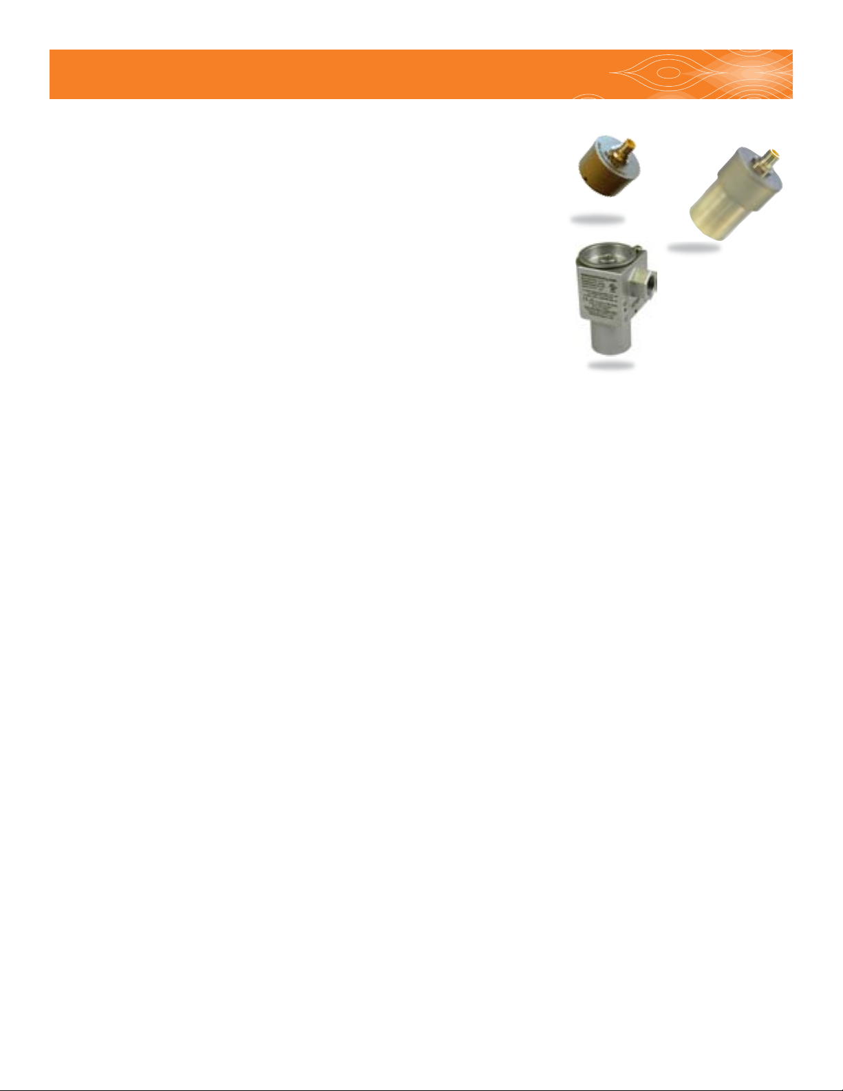
Model 296
entire family of Max Flow Meters to provide extremely precise
ow measurement in a cost effective package. Different options
for electrical connections and temperature ranges cover a wide
range of application environments – from the laboratory to harsh
industrial processes.
Model 295
This latest generation of transmitters use modern sensor
technology coupled with advanced signal processing to deliver
new levels of performance and reliability. Hall sensors are used to
Ex Proof Model 295
detect the position of a driven magnet inside a Max Flow Meter.
Changes in position are tracked by a microprocessor, which
generates an output proportional to the ow rate. Advanced signal processing provides both
ne angular resolution (0.36 degrees rotation) and rapid response (output updated every one
millisecond).
These transmitters are typically mated to a mechanical ow meter, congured, and calibrated at
the factory as a matched set. This ensures accuracy and allows quick setup in the eld. For eld
installations where the transmitter has not been setup with a meter at the factory, an optional serial
interface kit provides full access to all conguration options and parameters.
Transmitter Features
High resolution measurement - Congured output ranges to any valve within ± 10 Vdc or ± 20 mA.
Linearization of up to 16 points to fully describe the ow meter’s output curve and achieve the
highest system linearity over the meter’s entire operating range.
Compensation Algorithm – Compensates for variations in Hall sensor and ow meter characteristics
to provide a stable, undamped output that accurately represents the instantaneous ow rate. This
feature is factory set when the meter and transmitter are mated together. If the transmitter is
changed, the compensation can be performed via a button on the PCA.
Anti-Dither Buffer - Masks the false output that may occur at very low ow rates in the presence of
vibration or hydraulic noise. If the meter reverses direction the output signal will be interrupted for
a user selected portion of a meter rotation. Reverse ow exceeding the buffer setting will result in
an output proportional to reverse ow rate. The buffer quantity can be set from 1% to 100% of a
revolution.
IH 295-200-350 • rev. 6/2011 • ©2010-11 Max Machinery, Inc.
3
Page 4

Transmitter Specications
Supply Voltage 12 Vdc (Models 294-XXX-100 and G Series ending in B1 or D1)
24 Vdc (Models 294-XXX-000 and G Series ending in A1 or C1)
Supply Current Output 90 mA max@ 12 Vdc, 45 mA max@ 24 Vdc
(1)
Short Circuit Current
Output Update rate
Resolution Adjustable without recalibration to any range of ± 10 Vdc
(Model 29X-3XX-XXX or ± 20 mA Model 29X-2XX-XXX)
Ambient Temperature Range Transmitter (Storage)–40ºC to 85ºC (–40ºF to 185ºF)
Transmitter (Operation)
21 mA
(2)
1 ms
(3)
–40ºC to 80ºC (–40ºF to 175ºF)
Maximum Temperature, Process Fluid
(20ºC Ambient, 5V supply) 29X-X0X-XXX (Standard Model) 90ºC (195°F)
29X-X5X-XXX (High Temp Model) 155ºC (311°F)
Anti-dither Range 50% of a meter revolution - unidirectional - 2% bidirectional.
(software selectable from 1-100% of 1 revolution)
Signal Filtering Software selectable from 1 ms to 250 ms time constant
( 1) Continuous Short Circuit is not recommended. The output current should not exceed 10 mA
(2) Events are seen as output transitions 1 ms after they occur
(3) Temperature of metered uid will affect transmitter temperature, see graph
IH 295-200-350 • rev. 6/2011 • ©2010-11 Max Machinery, Inc.
4
Page 5

Installation - Model 295, 296
21
4
5
3
Model 295, 296 — Mechanical Installation
1. The transmitter is attached to the ow meter’s threaded magnet shield. Hand tighten only. (~ 3 ft-lb)
2. The transmitter lid has four thread paths. To realign the cable, remove the lid and rotate up to 180°
and retighten using an alternate starting point. Tighten to compress the O-ring seal.
Removal
1. Remove electrical connections
2. Unscrew transmitter, using a wrench if necessary.
Removal note: The transmitter does not need to be removed from the ow meter for any eld servicing or adjustments.
Normally, the ow meter and transmitter are shipped back to the factory for calibration or service as a unit. If the
transmitter needs to be removed from the ow meter for installation, be sure to retighten the transmitter snugly in order
to ensure proper sensor alignment.
Moisture Protection
On all models, the housing is designed as a liquid and vapor-tight enclosure. There are O—ring seals
at the lid and possibly also the base of the housing — these need to be fully seated. A properly sealed
transmitter will prevent the formation of damaging moisture inside the housing.
Turck connector Model: The connector is sealed to the lid at the factory and is ready for use.
NPT Model: To ensure a moisture-tight seal, apply appropriate sealant to the threads at installation.
Electrical Installation —
Wiring
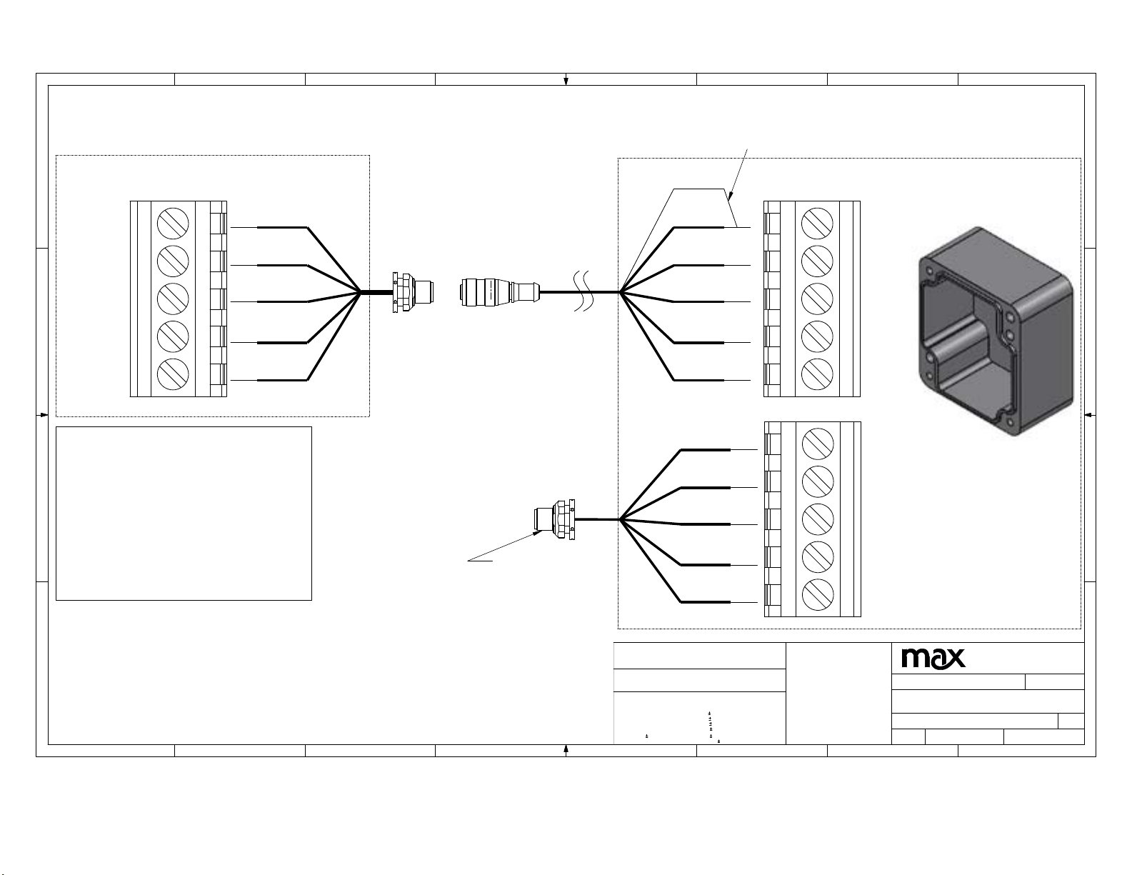
The electrical connector versions are pre-wired inside the transmitter and ready to accept a mating
cable (available from the factory). The liquid-tight, NPT models need to be wired during installation
as shown in the table below:
Liquid - tight
& NPT model
Connector
Terminal
Case Ground Case
Common Com Black 4
Power* V+
Signal Output (+) Sig Grey 5
Signal Output (—) ** RET White 2
Mating Cable
Wire Color
Blue
Brown
5-Pin Connector
Pin #
3
1
* Model 295-xxx-000, 24vdc powered, Model 295-xxx-100, 12vdc powered
** Signal output is fully isolated: If using a true differential input a 10K Ohm pulldown resistor
should be installed between (—) and common at the receiving end
IH 295-200-350 • rev. 6/2011 • ©2010-11 Max Machinery, Inc.
.
5
Page 6
8
7
56
4
3
2
1
Shield is only connected at the
receiver box end. MUST cover
shield with shrink wrap or tape
and connect to Brown/Com.
D
Meter Side Wiring
Shield
Receiver Box Wiring
D
Com
Rb
Ra
C
5v
Case
NOTE: For ha za rd ous
location installations,
customer must supp ly the ir
own ca bling a nd c onduit
B
between the mete r side
and the rec eiving box.
The rec eiving box must be
in a SAFE z o n e!
Brown
G re y
White
Black
Blue
Pigtail Connector from
Remote to Receiver
Use Standard
Cable for
Connection to
Instrumentation
Brown
G re y
White
Black
Blue
Brown
Bla c k
***
***
Blue
Com
Rb
Ra
5v
Case
V+
Com
PhA/Sig
Ph B/ Re t
Case
For Pulse
PhA -- White
PhB -- Grey
For Ana log
Sig -- Grey
Ret -- White
C
B
MATERIAL
A
8
7
6
5
FINISH
FOR FEATURES WITHOUT
DIMENSIONS, REFER TO
ELECTRONIC MODEL FILE.
UNLESS OTHERWISE
NOTED, TOLERANCE ON
THESE FEATURES IS
.010
4
MACHINED
STANDARD
TOLERANCES
.05
.X
.XX
.010
.003
.XXX
.XXXX
.0005
FRACT.
1/64
ANGULAR
BREAK ALL EDGES
DRAWN IN INCHES
3RD ANGLE PROJ.
1°
MAX SURFACE
FINISH 64
TO .010 - .015
3
*** COPYRIGHT ***
THIS DOCUMENT IS THE PROPERTY OF
MAX MACHINERY INC. AND CONTAINS
CONFIDENTIAL AND TRADE SECRET DATA
OF MAX MACHINERY INC. THIS DOCUMENT
MAY BE TRANSFERRED FROM THE CUSTODY
OR CONTROL OF MAX MACHINERY INC. ONLY
AS AUTHORIZED BY MAX MACHINERY INC.
AND THEN ONLY BY WAY OF LOAN FOR
LIMITED PURPOSES. IT MAY NOT BE
REPRODUCED IN WHOLE OR IN PART AND
MUST BE RETURNED TO MAX MACHINERY
INC. UPON REQUEST AND IN ALL EVENTS
UPON COMPLETIONS OF PURPOSE OF THE
LOAN. NEITHER THIS DOCUMENT NOR THE
INFORMATION IT CONTAINS MAY BE USED BY
OR DISCLOSED TO PERSONS NOT HAVING A
NEED FOR SUCH USE OR DISCLOSURE
CONSISTENT WITH THE PURPOSE OF THE
LOAN WITHOUT PRIOR WRITTEN CONSENT OF
MAX MACHINERY INC.
DESIGNER
bsnyder
DESCRIPTION
Wiring Diagram for Remote 295/296 Xmtrs
DRAWING
SIZE
D
2
TM
MAX MACHINERY
33A HEALDSBURG AVE
HEALDSBURG, CA 95448
DATE
8/23/11
SCALE
1:1
SHEET
OF
1
1
A
REV
-1
1
Page 7

Rotation/Output Indicators
All of the microprocessor based transmitters incorporate a LED to indicate that they are detecting
magnet rotation in the meter.
An alternating red/green or blue/green LED indicates that the circuit is detecting a rotating
magnet and should provide an output. Additional LED’s are present for setup, programming and
troubleshooting and are not intended for general use.
Note: There are no selections or adjustments to be made on the circuit board. The only method of
altering the setup parameters is through the serial interface program. Contact the factory regarding
P/N 294-100-050, user interface software.
Field Compensation of transmitter
When a new transmitter is attached to a ow meter, the compensation routine should be performed
to optimize the performance of the system. This routine requires a steady ow rate which turns
the meter at between 15 and 1000 RPM. If you are using the interface software, please consult the
“software Interface” manual for instructions. For the Model 295 and 296, the sequence is as follows:
1. Stabilize the ow rate
2. Push the compensation button on the PCA
3. The blue/green LED will change to solid blue for 6 to 8 revolutions of the meter
4. A green indicator light indicates a successful update of the compensation, a red indicator light
indicates that the previous compensation has been retained.
High Temperature Operation Above 65°C (150°F)
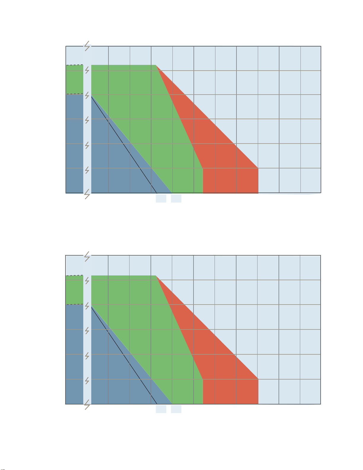
The operating limit of the meter/transmitter is a function of both the ambient and the metered uid
temperature, as shown in the following graphs. Although the electronic components are rated to
80°C (175°F), additional heat can be conducted from the ow meter into the transmitter housing
requiring a lower ambient temperature limit for high uid temperatures.
To prolong the life of the transmitter and reduce the risk of component related failures over time,
high ambient temperatures >65°C (150°F) should be avoided if possible. It is a good idea to locate
the transmitter away from hot spots such as steam pipes, ovens and heaters. When working with
elevated uid temperatures >65°C (150°F), insulating the ow meter is recommended to reduce the
risk of burns, and to reduce the heating of the electronics by convection of hot air off of the meter
(especially for larger meters). The upper temperature limits shown in the curves rely on ambient
convection to remove heat from the transmitter housing, cooling the electronics. For this reason,
if operating near the upper temperature limit, the transmitter should not be insulated. At these
elevated temperatures, the transmitter will be very hot — exercise appropriate caution.
IH 295-200-350 • rev. 6/2011 • ©2010-11 Max Machinery, Inc.
7
Page 8
Temperature Limits
Model 295 Transmitter Series
120
110
100
80
60
Ambient Temperature °C
40
One piece
model limits
20
0
-25
50
Process Temperature °C
Temperature Limits
Model 296 Transmitter Series
120
110
100
80
Standard
2 part pickup
110
100
(24Vdc)
125
(5Vdc)
In Development
2 part pickup
155
150 200
225
250
300
60
40
One piece
model limits
20
Ambient Temperature °C
0
-25
50
100
Process Temperature °C
IH 295-200-350 • rev. 6/2011 • ©2010-11 Max Machinery, Inc.
Standard
2 part pickup
110
125
(24Vdc)
(5Vdc)
In Development
2 part pickup
155
150 200
225
250
300
8
Page 9

Installation - Hazardous Locations
Applies only to Max Model EX295 and EX296 Transmitters with explosion proof certication.
These transmitters provide protection via a ame proof housing and through current limiting to the
circuit board: Must wire with a class 2 power supply (See table for loads).
Meets US and Canadian Haz-Loc classications, Class I, Div 1, Groups C and D, Tx
As well as ATEX/IECEx II 2 G Ex d IIB Tx Gb
Certication numbers Demko 11 ATEX 1013058X and IECEx UL 10.0048X
Mechanical Installation
The outer housing freely rotates to align the conduit hole with your electrical connection point. If
the transmitter is already attached to the meter skip to step 5:
1. To attach the transmitter to the ow meter, apply a small amount of low strength thread adhesive,
such as Loctite™, on the threads and screw the transmitter into the threaded recess on top of the
ow meter.
2. Locate the locking set screw below the conduit hole and remove it. Rotate the outer housing
clockwise until the screw hole lines up with a hole in the inner housing. Inserting an Allen key into the
threaded hole while rotating the housing can help in nding the point of alignment. Now re-insert the
set screw and hand-tighten it to lock the inner and outer housing together.
3. Finish tightening the transmitter onto the meter by applying a torque of 2 to 5 ft.-lb. (2.7 to 6.78 N-m).
4. Now back out the locking screw until it is ush with the surface of the transmitter.
5. The housing can now be rotated to align the conduit port in the desired direction.
6. To open the housing for wiring, remove the locking screw at the edge of the lid and then remove
the cap using a 3/8” socket drive.
7. Install conduit. Within 18” of the housing install a conduit stop and fully seal with potting compound.
8. Connect wires to terminal block as shown below.
9. A case ground terminal is provided internally, but if grounded metallic conduit is not used, then
one of the external grounds below the conduit tting must be used. For metric- use either a 6 or 8
mm long stainless steel M5 x 8.0 bolt.
steel #10-32 bolt.
For inch measurement – use either a 1/4” or 5/16” long stainless
10. Reattach cap and tighten to 40in-lbs to seal enclosure. Install safety lock screw at the edge of the
lid and hand tighten.
IH 295-200-350 • rev. 6/2011 • ©2010-11 Max Machinery, Inc.
9
Page 10
Removal from Flow Meter
Note: the transmitter does not need to be removed from the ow meter for any eld servicing
or adjustments. Normally, the ow meter and transmitter are shipped back to the factory for
calibration as a unit.
1. Remove the locking screw at the edge of the lid and then remove the cap using a 3/8” socket drive.
2. Disconnect wires at the terminal block and remove wiring conduit from transmitter.
3. Locate the locking set screw below the conduit hole and remove it. Rotate the outer housing
clockwise until the screw hole lines up with a hole in the inner housing. Inserting an Allen key into
the threaded hole while rotating the housing can help in nding the point of alignment. Now re-
insert the set screw and hand-tighten it. This will lock the inner and outer housing together.
4. Unscrew the transmitter, using a strap wrench if necessary.
Moisture Protection
The housing is a liquid and vapor-tight enclosure certied to IP66. There is an O-ring seal at the
lid of the housing — the seal needs to be fully seated to provide moisture protection and achieve
ameproof specications.
About Explosion proof installations
For the Model 295 and 296 to fully adhere to the HazLoc certications, the wiring must meet the
appropriate codes.
(Use of a wire conduit does not make the installation explosion proof – read below.)
The transmitters which are certied for use in hazardous locations require the use of a 1/2” NPT
conduit tting. The wiring conduit must be sealed with a conduit stop within 18” of the device. If
you choose to use exposed cables, cable seals must be used with sealing ttings and the wiring must
be an approved armored cable. (For detailed information on the joint constructions used to achieve
a ame proof housing, please contact Max Machinery.)
Electrical Installation
Use wiring that is between 20 and 28 gauge and rated to at least 5°C above the maximum ambient
temperature, and rated to at least 80% of the maximum uid temperature.
Pulse Output
Wiring
Case ground Case Blue Case Com Brown
Circuit Board
Label
Mating
Cable Wire
Color**
Analog Output
Wiring
Two Part Transmitter
End Labels
Wire Color
Common Com Black Com Rb Grey
Power* V+ Brown V+ Ra White
Signal Output (+) PHA White RET 5V Black
(Quad only) PHB Grey SIG Case Blue
* Consult Table
** (Color codes are typical for Max Machinery wired devices)
IH 295-200-350 • rev. 6/2011 • ©2010-11 Max Machinery, Inc.
10
Page 11
Electrical Requirements
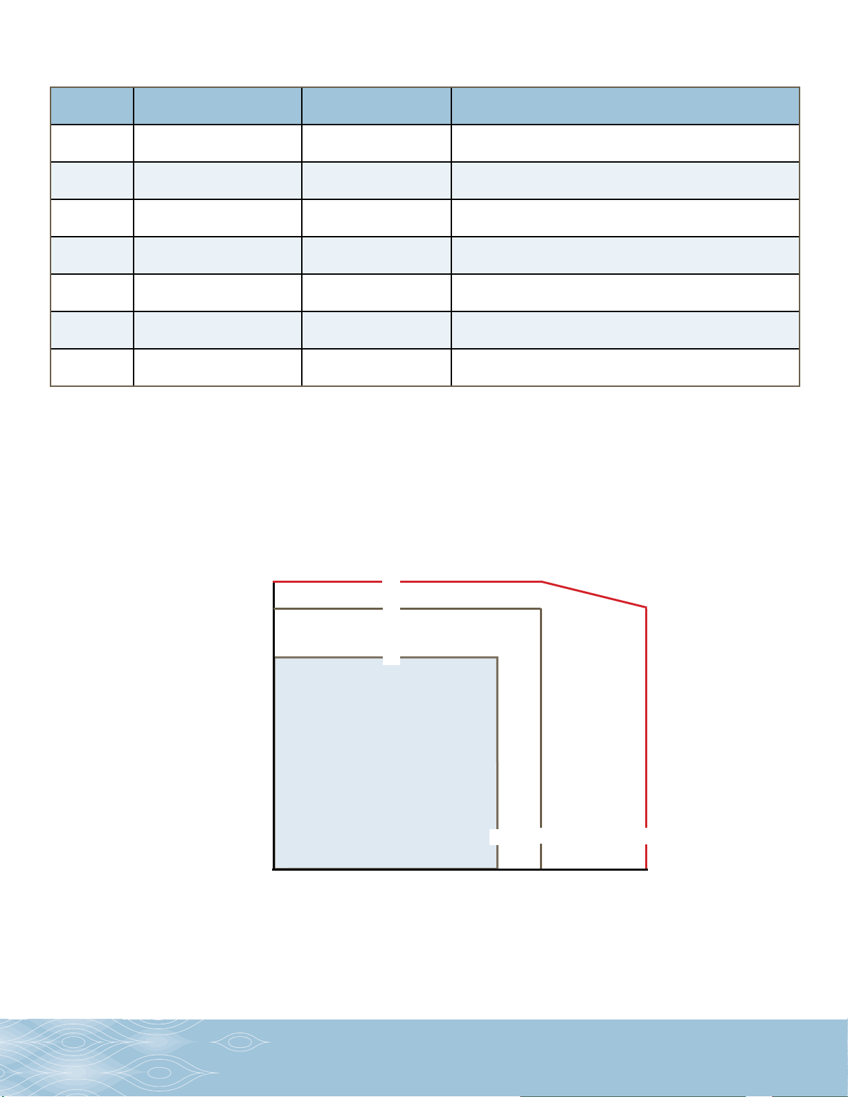
The device must be powered with a Class 2 power supply. Electrical loads are specic to model number’s:
Part #’s Transmitter Type
29x-0xx-0xx
29x-1xx-0xx
29x-2xx-0xx
29x-2xx-1xx
29x-3xx-0xx
29x-3xx-1xx
29x-6xx-0xx
Pulse Output Transmitter 5-28Vdc 40mA Single Line 0-5V 10mA (500 ohm pulldown or greater)
Quadrature Output
Transmitter
mA Output Transmitter
(24Vdc)
mA Output Transmitter
(12Vdc)
V Output Transmitter
(24Vdc)
V Output Transmitter
(12Vdc)
Level Shifter Pulse Output
Transmitter
Electrical Input
Requirements
5-28Vdc 50mA 2 Lines 0-5V 10mA each (500 ohm pulldown or greater)
24-28Vdc 50mA Isolated current loop, max 500 ohms in line, 12Vdc max
12-15Vdc 100mA Isolated current loop, max 500 ohms in line, 12Vdc max
24-28Vdc 50mA Isolated voltage loop, max 500 ohms in line, 12Vdc max
12-15Vdc 100mA Isolated voltage loop, max 500 ohms in line, 12Vdc max
5-28Vdc 30mA Single line, current sinking, max 28Vdc, max 25mA
Output Electrical Requirements
Temperature Classication
Temperature class is a function of uid temperature used in the meter and ambient temperature.
For hot uids, meter must be insulated and transmitter must be left exposed. All transmitters are
rated to operate within the BLUE region, but only the remote sender unit variants (295-x5x-xxx) can
operate up to the maximum temperatures shown in the chart. Consult factory for installation details
when operating near temperature limits.
Temperature class chart for all explosion proof variants:
100-
90 -
80-
75-
60-
100
90
75
T6 T5 T4
40-
20-
Ambient Temperature °C
-25
0
20
40
75 90 130
60
80
100
120
130
Fluid Temperature °C
Note: Consult factory to determine the functional temperature limit of your transmitter variant. Temperature class
ratings do not correspond with the continuous duty area for the electronics within the transmitter. A complete
description of your transmitter may be found on the Max Machinery web site (www.maxmachinery.com). Individual
specication sheets and product family manuals are also available for viewing or downloading.
Max Machinery, Inc.
maxmachinery.com
33A Healdsburg Avenue
Healdsburg,
CA 95448
T
+1 707. 433.2662
F
+1 707. 4 33.1818
11
Page 12

EC Declaration of Conformity
We, Max Machinery Inc. declare as manufacturer under our sole responsibility that the product
series 295/296 Explosion Proof Flow Transmitter is in conformity with the provisions of the
European Community Directives as shown below.
Applicable Series: Part numbers of the format 295-xx1-x00 and 296-xx1-x00 where ‘x’ does not
affect conformity to the standards.
Low Voltage Directive 2006/95/EC
EMC Directive 2004/108/EC
EN 61000-6-2:2005 Electromagnetic Immunity
EN 61000-6-4:2007 Electromagnetic Emission
ATEX Directive 94/9/EC designed and manufactured in accordance with Annex II of the Atex Directive
EN 60079-0:2009 Explosive atmospheres general requirements
(Note: no routine verication and tests are required by clause 27)
EN 60079-1:2007 Protection by ameproof enclosures type d”
Designation: 0539 II 2 G Ex d IIB Tx Gb
EC Type examination certicate DEMKO 11 ATEX 1013058X provided by
UL International DEMKO A/S NB Number: 0539
P.O. Box 514, Lyskaer 8, DK-2730 Herlev, Denmark
Product quality assurance notication #11 ATEX Q1116140 provided by UL Demko
Production control done to ISO 9001:2008, certicate #C2010-01864
May 24, 2011
Bryan Snyder Max Machinery Inc.
Engineering Manager 33A Healdsburg Ave.
Healdsburg, CA USA
(707) 433-2662
IH 295-200-350 • rev. 6/2011 • ©2010-11 Max Machinery, Inc.
12
 Loading...