

Page 1

INSTRUCTION MANUAL
121 INDICATOR
TABLE OF CONTENTS
1. DESCRIPTION
1.1 Unit Description . . . . . . . . . . . . . . . . . . . . . . . . . . . . . . . . . . . . . . . . . . . . . . . . . . . . . . . . . 4
1.2 Unit Features . . . . . . . . . . . . . . . . . . . . . . . . . . . . . . . . . . . . . . . . . . . . . . . . . . . . . . . . . . . . 4
1.3 Specifications . . . . . . . . . . . . . . . . . . . . . . . . . . . . . . . . . . . . . . . . . . . . . . . . . . . . . . . . . . . 5
2. INSTALLATION
2.1 General Mounting Hints . . . . . . . . . . . . . . . . . . . . . . . . . . . . . . . . . . . . . . . . . . . . . . . . . . . 9
2.2 Mounting Diagrams . . . . . . . . . . . . . . . . . . . . . . . . . . . . . . . . . . . . . . . . . . . . . . . . . . . . . . . 9
3. APPLICATIONS
3.1 Liquid Volume . . . . . . . . . . . . . . . . . . . . . . . . . . . . . . . . . . . . . . . . . . . . . . . . . . . . . . . . . . 10
3.2 Corrected Liquid Volume . . . . . . . . . . . . . . . . . . . . . . . . . . . . . . . . . . . . . . . . . . . . . . . . . . 11
3.3 Liquid Mass . . . . . . . . . . . . . . . . . . . . . . . . . . . . . . . . . . . . . . . . . . . . . . . . . . . . . . . . . . . 12
3.4 Batching . . . . . . . . . . . . . . . . . . . . . . . . . . . . . . . . . . . . . . . . . . . . . . . . . . . . . . . . . . . . . . 13
4. WIRING
4.1 Typical Batcher Wiring . . . . . . . . . . . . . . . . . . . . . . . . . . . . . . . . . . . . . . . . . . . . . . . . . . . 14
4.2 Typical Rate/Total Wiring . . . . . . . . . . . . . . . . . . . . . . . . . . . . . . . . . . . . . . . . . . . . . . . . . 14
5. UNIT OPERATION
5.1 Front Panel Operation Concept for Run Mode . . . . . . . . . . . . . . . . . . . . . . . . . . . . . . . . . . 15
5.2 General Operation . . . . . . . . . . . . . . . . . . . . . . . . . . . . . . . . . . . . . . . . . . . . . . . . . . . . . . . 16
5.3 Ratemeter/Totalizer Operation . . . . . . . . . . . . . . . . . . . . . . . . . . . . . . . . . . . . . . . . . . . . . . 16
5.3.1 Password Protection for Rate/Total mode . . . . . . . . . . . . . . . . . . . . . . . . . . . . . . . . . . . . 16
5.3.2 Relay Operation in Rate/Total mode . . . . . . . . . . . . . . . . . . . . . . . . . . . . . . . . . . . . . . . . 16
5.3.3 Pulse Output in Rate/Total mode . . . . . . . . . . . . . . . . . . . . . . . . . . . . . . . . . . . . . . . . . . 16
5.3.4 Analog Output in Rate/Total mode . . . . . . . . . . . . . . . . . . . . . . . . . . . . . . . . . . . . . . . . . 16
5.3.5 RS-232 Serial Port Operation in Rate/Total mode . . . . . . . . . . . . . . . . . . . . . . . . . . . . . . 16
5.4 Batcher Operation . . . . . . . . . . . . . . . . . . . . . . . . . . . . . . . . . . . . . . . . . . . . . . . . . . . . . . . 17
5.4.1 Batcher Configuration . . . . . . . . . . . . . . . . . . . . . . . . . . . . . . . . . . . . . . . . . . . . . . . . . . 17
5.4.2 Password Protection for Batcher mode . . . . . . . . . . . . . . . . . . . . . . . . . . . . . . . . . . . . . . 18
5.4.3 Relay Operation in Batcher mode . . . . . . . . . . . . . . . . . . . . . . . . . . . . . . . . . . . . . . . . . . 18
5.4.4 Pulse Output in Batcher mode . . . . . . . . . . . . . . . . . . . . . . . . . . . . . . . . . . . . . . . . . . . . 19
5.4.5 Analog Output in Batcher mode . . . . . . . . . . . . . . . . . . . . . . . . . . . . . . . . . . . . . . . . . . . 19
5.4.6 RS-232 Serial Port Operation in Batcher mode . . . . . . . . . . . . . . . . . . . . . . . . . . . . . . . . 19
6. PROGRAMMING
6.1 Front Panel Operation Concept for Program Mode . . . . . . . . . . . . . . . . . . . . . . . . . . . . . . 20
6.2 EZ Setup . . . . . . . . . . . . . . . . . . . . . . . . . . . . . . . . . . . . . . . . . . . . . . . . . . . . . . . . . . . . . . 21
6.3 Setup Menus . . . . . . . . . . . . . . . . . . . . . . . . . . . . . . . . . . . . . . . . . . . . . . . . . . . . . . . . . . . 22
6.4 Setup Sub-Menus . . . . . . . . . . . . . . . . . . . . . . . . . . . . . . . . . . . . . . . . . . . . . . . . . . . . . . . 23
6.4.1 SELECT EZ SETUP . . . . . . . . . . . . . . . . . . . . . . . . . . . . . . . . . . . . . . . . . . . . . . . . . . . 23
6.4.2 INSTRUMENT TYPE . . . . . . . . . . . . . . . . . . . . . . . . . . . . . . . . . . . . . . . . . . . . . . . . . . 23
6.4.3 SELECT FLOW EQUATION . . . . . . . . . . . . . . . . . . . . . . . . . . . . . . . . . . . . . . . . . . . . . 24
6.4.4 SETUP INDICATORS (Total) . . . . . . . . . . . . . . . . . . . . . . . . . . . . . . . . . . . . . . . . . . . . 24
6.4.5 SETUP INDICATORS (Density) . . . . . . . . . . . . . . . . . . . . . . . . . . . . . . . . . . . . . . . . . . 24
Page 2

6.4.6 SETUP INDICATORS (Rate)............................................................................................... 25
6.4.7 SETUP INDICATORS (Temperature).................................................................................. 25
6.4.8 SETUP FLOW INPUT (Pulse - Ain & PS (A=B)).............................................................. 26
6.4.9 SETUP FLOW INPUT (Pulse - Quadrature, Qx1 or Qx2).................................................. 27
6.4.10 SETUP FLOW INPUT (Analog)........................................................................................ 28
6.4.11 SETUP AUX INPUT.......................................................................................................... 29
6.4.12 SET FLUID PROPERTIES................................................................................................ 30
6.4.13 SETUP PULSE OUTPUT .................................................................................................. 30
6.4.14 SETUPANALOG OUTPUT.............................................................................................. 31
6.4.15 SETUP RELAYS................................................................................................................ 31
6.4.16 SETUP CONTROL INPUTS(RATE/TOTAL)................................................................... 33
6.4.17 SETUP CONTROL INPUTS(BATCH).............................................................................. 33
6.4.18 SETUP REALTIME CLOCK(Time).................................................................................. 34
6.4.19 SETUP REALTIME CLOCK(Date)................................................................................... 34
6.4.20 SERIAL USAGE................................................................................................................ 35
6.4.21 SET DATALOG/PRINT(Configure).................................................................................. 36
6.4.22 SET DATALOG/PRINT (Select_list)................................................................................. 37
6.4.23 ADMINISTRATIVE SETUP.............................................................................................. 37
6.4.24 SETUP NETWORK CARD............................................................................................... 38
7. PRINCIPLE OF OPERATION
7.1 General..................................................................................................................................... 39
7.3 Flow Equations........................................................................................................................ 39
7.4 Calculating the Expansion Factor............................................................................................ 41
7.6 Linearization Table.................................................................................................................. 42
7.6.1 Linearization Table General Information ............................................................................. 42
7.6.2 Linearization Table for Pulse Inputs..................................................................................... 42
7.6.3 Linearization Table for Analog Inputs.................................................................................. 42
8. TEST, SERVICE and MAINTENANCE
8.1 Test Menus............................................................................................................................... 43
8.2 Test Sub-Menus ....................................................................................................................... 44
8.2.1 Audit Trail............................................................................................................................. 44
8.2.2 Error History......................................................................................................................... 44
8.2.3 Print System Setup................................................................................................................ 44
8.2.4 Keypad test ........................................................................................................................... 45
8.2.5 Display test ........................................................................................................................... 45
8.2.6 Calibrate CH1 0mA.............................................................................................................. 46
8.2.7 Calibrate CH1 20mA............................................................................................................ 46
8.2.8 Calibrate CH2 0mA.............................................................................................................. 47
8.2.9 Calibrate CH2 20mA............................................................................................................ 47
8.2.10 Calibrate CH1 0V............................................................................................................... 48
8.2.11 Calibrate CH1 10V ............................................................................................................. 48
8.2.12 Calibrate CH2 0V............................................................................................................... 49
8.2.13 Calibrate CH2 10V............................................................................................................. 49
8.2.14 Calibrate 100 ohm RTD...................................................................................................... 49
8.2.15 Calibrate 4mA Out.............................................................................................................. 50
8.2.16 Calibrate 20mA Out............................................................................................................ 50
8.2.17 Analog In Test..................................................................................................................... 50
Page 3

8.2.18 Pulse input test . . . . . . . . . . . . . . . . . . . . . . . . . . . . . . . . . . . . . . . . . . . . . . . . . . . . . . . 51
8.2.19 Analog out test . . . . . . . . . . . . . . . . . . . . . . . . . . . . . . . . . . . . . . . . . . . . . . . . . . . . . . . 51
8.2.20 Excitation out test . . . . . . . . . . . . . . . . . . . . . . . . . . . . . . . . . . . . . . . . . . . . . . . . . . . . . 51
8.2.21 Pulse out test . . . . . . . . . . . . . . . . . . . . . . . . . . . . . . . . . . . . . . . . . . . . . . . . . . . . . . . . 52
8.2.22 Relay test . . . . . . . . . . . . . . . . . . . . . . . . . . . . . . . . . . . . . . . . . . . . . . . . . . . . . . . . . . . 52
8.2.23 Control input test . . . . . . . . . . . . . . . . . . . . . . . . . . . . . . . . . . . . . . . . . . . . . . . . . . . . . 52
8.2.24 Battery Voltage test . . . . . . . . . . . . . . . . . . . . . . . . . . . . . . . . . . . . . . . . . . . . . . . . . . . . 53
8.2.25 Data logger utility . . . . . . . . . . . . . . . . . . . . . . . . . . . . . . . . . . . . . . . . . . . . . . . . . . . . . 53
8.3 Internal Fuse Replacement . . . . . . . . . . . . . . . . . . . . . . . . . . . . . . . . . . . . . . . . . . . . . . . . . 54
9. RS-232 SERIAL PORT
9.1 RS-232 Serial Port Description . . . . . . . . . . . . . . . . . . . . . . . . . . . . . . . . . . . . . . . . . . . . . 55
9.2 Instrument Setup by PC Over Serial Port . . . . . . . . . . . . . . . . . . . . . . . . . . . . . . . . . . . . . . 55
9.3 Operation of Serial Communication Port with Printers . . . . . . . . . . . . . . . . . . . . . . . . . . . 55
9.4 121 Series RS-232 Port Pinout . . . . . . . . . . . . . . . . . . . . . . . . . . . . . . . . . . . . . . . . . . . . . 55
10. RS-485 SERIAL PORT
11. FLOW COMPUTER SETUP SOFTWARE
11.1 System Requirements . . . . . . . . . . . . . . . . . . . . . . . . . . . . . . . . . . . . . . . . . . . . . . . . . . . 56
11.2 Cable and Wiring Requirements . . . . . . . . . . . . . . . . . . . . . . . . . . . . . . . . . . . . . . . . . . . . 56
11.3 Installation for Windows™3.1 or 3.11 . . . . . . . . . . . . . . . . . . . . . . . . . . . . . . . . . . . . . . . 56
11.4 Using the Flow Computer Setup Software . . . . . . . . . . . . . . . . . . . . . . . . . . . . . . . . . . . . 56
11.5 File Tab . . . . . . . . . . . . . . . . . . . . . . . . . . . . . . . . . . . . . . . . . . . . . . . . . . . . . . . . . . . . . . 57
11.6 Setup Tab . . . . . . . . . . . . . . . . . . . . . . . . . . . . . . . . . . . . . . . . . . . . . . . . . . . . . . . . . . . . 57
11.7 View Tab . . . . . . . . . . . . . . . . . . . . . . . . . . . . . . . . . . . . . . . . . . . . . . . . . . . . . . . . . . . . . 58
11.8 Misc. Tab . . . . . . . . . . . . . . . . . . . . . . . . . . . . . . . . . . . . . . . . . . . . . . . . . . . . . . . . . . . . . 58
12. GLOSSARY OF TERMS
12 Glossary Of Terms . . . . . . . . . . . . . . . . . . . . . . . . . . . . . . . . . . . . . . . . . . . . . . . . . . . . . . . 59
13. DIAGNOSIS AND TROUBLESHOOTING
13.1 Response of 121 Series on Error or Alarm . . . . . . . . . . . . . . . . . . . . . . . . . . . . . . . . . . . . 63
13.2 Diagnosis Flow Chart and Troubleshooting . . . . . . . . . . . . . . . . . . . . . . . . . . . . . . . . . . . 64
13.3 Error & Warning Messages: . . . . . . . . . . . . . . . . . . . . . . . . . . . . . . . . . . . . . . . . . . . . . . . 65
13.3.1 Sensor/Process Alarms . . . . . . . . . . . . . . . . . . . . . . . . . . . . . . . . . . . . . . . . . . . . . . . . . 65
13.3.2 Self Test Alarms . . . . . . . . . . . . . . . . . . . . . . . . . . . . . . . . . . . . . . . . . . . . . . . . . . . . . . 66
APPENDIX A
Setup Menus . . . . . . . . . . . . . . . . . . . . . . . . . . . . . . . . . . . . . . . . . . . . . . . . . . . . . . . . . . . . . . 68
DO NOT ATTEMPT TO INSTALL OR START FLOWMETER
WITHOUT READING THIS ENTIRE MANUAL
121-000-350 © 2001 Max Machinery, Inc.
Max Machinery, Inc. reserves the right to make changes to the product in this Instruction
Manual to improve performance, reliability, or manufacturability. Consequently, contact
MMI for the latest available specifications and performance data.
Although every effort has been made to ensure accuracy of the information contained in
this Instruction Manual, MMI assumes no responsibility for inadvertent errors
Page 4

General Description
1. Description
1.1 Unit Description:
The Max Model 121 Flow Computer satisfies the instrument requirements for a variety of flowmeter
types in liquid applications. Multiple flow equations and instrument functions are available in a single
unit with many advanced features.
The alphanumeric display shows measured and calculated parameters in an easy to understand format.
Single key direct access to measurements and display scrolling is supported.
The versatility of the Model 121 permits a wide measure of versatility within the instrument package.
The various hardware inputs and outputs can be “soft” assigned to meet a variety of common a p p l i c a t i o n
needs. The user “soft selects” the usage of each input/output while configuring the instrument. Consider
the following illustrative examples.
The isolated analog output can be chosen to follow volume flow, corrected volume flow, mass flow, temperature, or density by means of a menu selection. Most hardware features are assignable by this
method.
The user can assign the standard RS-232 Serial Port for data logging, transaction printing, or for connection to a modem for remote meter reading.
1.2 Unit Features:
The Model 121 Flow Computer offers the following features:
• Multiple Instrument Functions
• Menu Selectable Hardware & Software Features
• Two Line VFD Display
• Isolated Outputs Standard
• Versatile RS-232 Port Standard
• DIN Enclosure with Two Piece Connector
• Advanced Batching Features
Pg 4 121-000-350 © 2001 Max Machinery, Inc.
Page 5

Specifications
Specifications:
Environmental
Indoor Use
Altitude up to 2000m
Operating Temperature: 0C to +50C
Storage Temperature: -40C to +85C
Maximum Relative Humidity : 80% for temperatures
up to 31C decreasing linearly to 50% RH at 40C
Main supply voltage fluctuations not to exceed ±10%
of the nominal voltage
Transient overvoltage according to INSTALLATION
CATEGORY II (see UL 3101-1 Annex J)
POLLUTION DEGREE 2 in accordance with
IEC 664 (see 3.7.3)
Materials: UL, CSA, VDE approved
Approvals: CE Approved Light Industrial,
UL File #: E192404
CSA Pending
Display
Type: 2 lines of 20 characters
Type: VFD
Character Size: 0.3" nominal
User selectable label descriptors and units of measure
Keypad
Keypad Type: Membrane Keypad
Keypad Rating: Sealed to NEMA 4
Number of keys: 16
Enclosure
Size: See Dimensions on page 9
Depth behind panel: 6.5" including mating connector
Type: DIN
Materials: Plastic, UL94V-0, Flame retardant
Bezel: Textured per matt finish
Equipment Labels: Model, safety, and user wiring
Power Input
The factory equipped power option is internally fused.
An internal line to line filter capacitor is provided for
added transient suppression.
121-200: 110VAC: 85 to 127 Vrms, 50/60 Hz
121-201: 12VDC: 10.5 to 14 VDC
Control Inputs
Switch Inputs are menu selectable for Start, Stop,
Reset, Lock, Inhibit, Alarm Acknowledge, Print or Not
U s e d .
Control Input Specifications
Input Scan Rate: 10 scans per second
Logic 1: 4 - 30 VDC
Logic 0: 0 - 0.8 VDC
Transient Suppression: 500 V fast transient
(Capacitive Clamp)
Input Impedance: 100 K
Control Activation: Positive Edge or Pos. Level
based on product definition
Flow Inputs:
Analog Input:
Ranges
Voltage: 0-10 VDC, 0-5 VDC, 1-5 VDC
Current: 4-20 mA, 0-20 mA
Basic Measurement Resolution: 16 bit
Update Rate: 5 updates/sec minimum
Automatic Fault detection: Signal over/under-range,
Current Loop Broken
Calibration: Self Calibration and Auto-zero continuously
Extended calibration: Learns Zero and Full Scale
of each range using special test mode.
Fault Protection:
Fast Transient: 500 V Protection
(Capacitive Clamp)
Reverse Polarity: No ill effects
Over-Voltage Limit: 50 VDC Over voltage protection
Over-Current Protection: Internally current limited
Protected to 24 VDC.
Compensation Input
The compensation input is menu selectable for
temperature, density or not used.
Operation: Ratiometric
Accuracy: 0.01% FS
Thermal Drift: Less than 100 ppm/oC
Basic Measurement Resolution: 16 bit
Update Rate: 1 update/sec minimum
Automatic Fault detection:
Signal Over-range/under-range
Current Loop Broken
RTD short
RTD open
Fault mode to user defined default settings
Transient Protection: 500 V (Capacitive Clamp)
Reverse Polarity: No ill effects
Over-Voltage Limit (Voltage Input): 50 VDC
A vailable Input Ranges
Voltage: 0-10 VDC, 0-5 VDC, 1-5 VDC
Current: 4-20 mA, 0-20 mA
Resistance: 100 Ohms DIN RTD
100 Ohm DIN RTD (DIN 42-760, BS 1904):
Three Wire Lead Compensation
Internal RTD linearization learns ice point
resistance
1 mA Excitation current with reverse polarity protection
Temperature Resolution: 0.01 C
Excitation Voltage
110/220 VAC Powered Units
Menu Selectable: 5, 12 or 24 VDC @ 100mA
12 VDC Powered Units
5 VDC @ 100mA
121-000-350 © 2001 Max Machinery, Inc. Pg 5
Page 6

Specifications
Pulse Inputs:
Number of Flow Inputs: one
Configurations supported: single input with or
without quadrature (menu selectable)
Input Impedance: 10 K nominal
Pullup Resistance: 10 K to 5 VDC (menu selectable)
Pull Down Resistance: 10 K to common
Trigger Level: (menu selectable)
High Level Input
Logic On: 3 to 30 VDC
Logic Off: 0 to 1 VDC
Low Level Input (mag pickup)
Selectable sensitivity: 10 mV & 100 mV
Minimum Count Speed: User selectable
Maximum Count Speed: Selectable: 0 to 20kHz
Overvoltage Protection: 50 VDC
Fast Transient: Protected to 500 VDC
(Capacitive Clamp)
Relay Outputs
The relay outputs are menu assignable to (individually
for each relay) Low Rate Alarm, Hi Rate Alarm,
Prewarn Alarm, Preset Alarm, Pulse Output (pulse
options) or General purpose warning (security).
Number of relays: 2
Contact Style: Form C contacts
Contact Ratings:
250 VAC @ 5 amps
30 VDC @ 5 amps
Fast Transient Threshold: 1000 V
Serial Communication
The serial port can be used for printing, datalogging,
modem connection and communication with a computer.
Analog Output
The analog output is menu assignable to correspond
to the Uncompensated Volume Rate, Corrected
Volume Rate, Mass Rate, Temperature, Density,
Volume Total, Corrected Volume Total or Mass Total.
Type: Isolated Current Sourcing
Isolated I/P/C: 500 V
Available Ranges: 4-20 mA, 0-20 mA
Resolution: 12 bit
Accuracy: 0.05% FS at 20 Degrees C
Update Rate: 1 update/sec minimum
Temperature Drift: Less than 200 ppm/OC
Maximum Load: 1000 ohms (at nominal line voltage)
Compliance Effect: Less than .05% Span
60 Hz rejection: 40 dB minimum
EMI: No effect at 3 V/M
Calibration: Operator assisted Learn Mode
Averaging: User entry of DSPAveraging constant
to cause a smooth control action.
Isolated Pulse output
The isolated pulse output is menu assignable to
Uncompensated Volume Total, Compensated
Volume Total or Mass Total.
Isolation I/O/P: 500 V
Pulse Output Form: Open Collector
Maximum On Current: 125 mA
Maximum Off Voltage: 30 VDC
Saturation Voltage: 1.0 VDC
Maximum Off Current: 0.1 mA
Pulse Duration: User selectable
Pulse output buffer: 8 bit
Pulse Rate Averaging: Standard
Fault Protection
Reverse polarity: Shunt Diode
Transient Protection: 500 VDC (Capacitive Clamp)
Operating Mode
The Flow Computer can be thought of as making a
series of measurements of flow, temperature/
density sensors and then performing calculations
to arrive at a result(s) which is then updated
periodically on the display. The analog output,
the pulse output, and the alarm relays are also
updated. The cycle then repeats itself.
Step 1: Update the measurements of input signals-
Raw Input Measurements are made at each
input using equations based on input signal
type selected. The system notes the “out of
range” input signal as an alarm condition.
Step 2: Compute the Flowing Fluid Parameters-The
temperature, viscosity, and density equations
are computed as needed based on the flow
equation and input usage selected by the
user.
Step 3 : Compute the Volumetric Flow-Uncompensated
flow is the term given to the flow in volume
units. The value is computed based on the
flowmeter input type selected and augmented by
any performance enhancing linearization that has
been specified by the user.
Step 4: Compute the Corrected Volume Flow at
Reference Conditions-In the case of a corrected
liquid volume flow calculation, the corrected
volume flow is computed as required by the
selected compensation equation.
Step 5 : Compute the Mass Flow-All required
information is now available to compute the
mass flow rate as volume flow times density.
Step 6: Check Flow Alarms-The flow alarm functions
have been assigned to one of the above flow
rates during the setup of the instrument. A
Pg 6 121-000-350 © 2001 Max Machinery, Inc.
Page 7

Specifications
comparison is now made by comparing the
current flow rates against the specified hi and
low limits.
Step 7: Compute the Analog Output-This designated
flow rate value is now used to compute the
analog output.
Step 8: Compute the Flow Totals by Summation-A
flow total increment is computed for each flow
rate. This increment is computed by multiplying
the respective flow rate by a time base scaler and
then summing. The totalizer format also includes
provisions for total rollover.
Step 9: Total Preset Comparisons-The total associated
with a preset function is then compared
against the corresponding preset value and any
required control actions taken.
Step 10: Pulse Output Service-The pulse output is next
updated by scaling the total increment which has
just been determined by the pulse output scaler
and summing it to any residual pulse output
amount.
Step 11: Update Display and Printer Output-The
instrument finally runs a task to update the
various table entries associated with the front
panel display and serial outputs.
Setup Mode
The setup mode is password protected by means
of a numeric lock out code established by the
user. In addition, a secret, manufacturer’s
numeric unlock entry sequence is available.
The system also provides a minimum
implemetation of an “audit trail” which tracks
significant setup changes to the unit. This feature
is increasingly being found of benefit to users or
simply required by Weights and Measurement
Officials in systems used in commerce, trade, or
“custody transfer” applications.
A Worksheet is provided to assist the user in
setting up the instrument. In addition, a software
program is available which runs on a PC using a
RS-232 Serial connection to the Flow
Computer. Illustrative examples may be down
loaded in this manner.
The setup mode has numerous subgrouping of
parameters needed for flow calculations. There
is a well conceived hierarchy to the setup
parameter list. Selections made at the
beginning of the setup affect offerings further
down in the lists.
In the setup mode, the flow computer
activates the correct setup variables based on
the instrument configuration, the flow
equation, and the hardware selections made
for the compensation transmitter type, the
flow transmitter type, and meter
enhancements (linearization) options
selected. All required setup parameters are
enabled. All setup parameters not required
are suppressed.
A help line prompt is provided for each entry.
In addition a help message is available which
may be accessed by depressing the “HELP”
key.
In the setup mode selections, several parameters
are required to be input by the operator
since these parameters are blank when the
unit is received. The user will be prompted
for these necessary values for his application.
A blank parameter will prevent the user from
entering the run mode and a suitable warning
message will be issued.
Also note that in the setup mode there are
parameter selections which have preassigned
industry standard values. The unit will assume
these values unless they are modified by the
user.
Most of the process input variables have
available a “default” or emergency value
which must be entered. These are the values
that the unit assumes when a malfunction is
determined to have occurred on the
corresponding input.
Hint: It is possible to enter in a nominal constant
value for temperature or density, or analog
flow inputs by placing the desired nominal
value into both the lo and hi values. This is
also a convenience when performing bench top
tests without simulators.
Maintenance Mode:
The Maintenance Mode of the 121 Series is the
Test and Calibration Mode for the device. This
mode provides a number of specialized utilities
required for factory calibration, instrument
checkout on start-up, and periodic calibration
documentation.
A password is required to gain access to this
specialized mode of operation. Normally
121-000-350 © 2001 Max Machinery, Inc. Pg 7
Page 8

Specifications
quality, calibration, and maintenance personnel
will find this mode of operation very useful. It is
also useful for factory testing.
Many of these tests may be used during start-up
of a new system. Inputs signals may be read, and
output signals may be exercised to verify the
electrical interconnects before the entire system
is put on line.
The following action items may be performed in
the Maintenance Mode:
Print Calibration/Maintenance Report
Examine Audit Trail
Perform Keypad Checkout
Perform Display Checkout
Perform Pulse Input Checkout
Perform Pulse Output Checkout
Perform Control Input Checkout
Perform Relay Output Checkout
Perform Analog Input Checkout
Perform Analog Output Checkout
Calibrate Analog Inputs using the Learn Feature
Calibrate Analog Output using the Learn Feature
Battery Check
Note that a calibration of the analog input/output
will advance the audit trail counters since it
effects the accuracy of the system.
RS-232 Serial Port
The 121 Series has a general purpose RS-232 Port
which may be used for any one of the following
purposes:
logging and/or printing of calibration and
maintenance reports.
For transaction printing, the user defines the items
to be included in the printed document. The user
can also select what initiates the transaction print
generated as part of the setup of the instrument.
The transaction document may be initiated via a
front panel key depression, a remote contact
closure, or upon completion of a batch.
In data logging, the user defines the items to be
included in each data log as a print list. The user
can also select when or how often he wishes a
data log to be made. This is done during the setup
of the instrument as either a time of day or as a
time interval between logging.
The system setup and maintenance report lists all
the instrument setup parameters and usage for the
current instrument configuration. In addition, the
Audit trail information is presented along with a
status report listing any observed malfunctions
which have not been corrected.
The user initiates the printing of this report at a
designated point in the menu by pressing the print
key on the front panel.
Transaction Printing
Data Logging Internal Datalog Dumps
Computer Communication Link
Configuration by Computer
Print System Setup
Print Calibration/Malfunction History
Remote Control
Instrument Setup by PC’s over Serial Port
A Diskette program is provided with the 121 Series
that enables the user to rapidly configure the indicator
using a Personnel Computer. Included on the diskette
are common instrument applications which may be
used as a starting point for your application. This
permits the user to have an excellent starting point
and helps speed the user through the instrument setup.
Operation of Serial Communication Port with
Printers
121 Series’s RS-232 channel supports a number of
operating modes. One of these modes is intended to
support operation with a printer in metering
applications requiring transaction printing, data
Pg 8 121-000-350 © 2001 Max Machinery, Inc.
Page 9
Installation
(157)
2.1 General Mounting Hints:
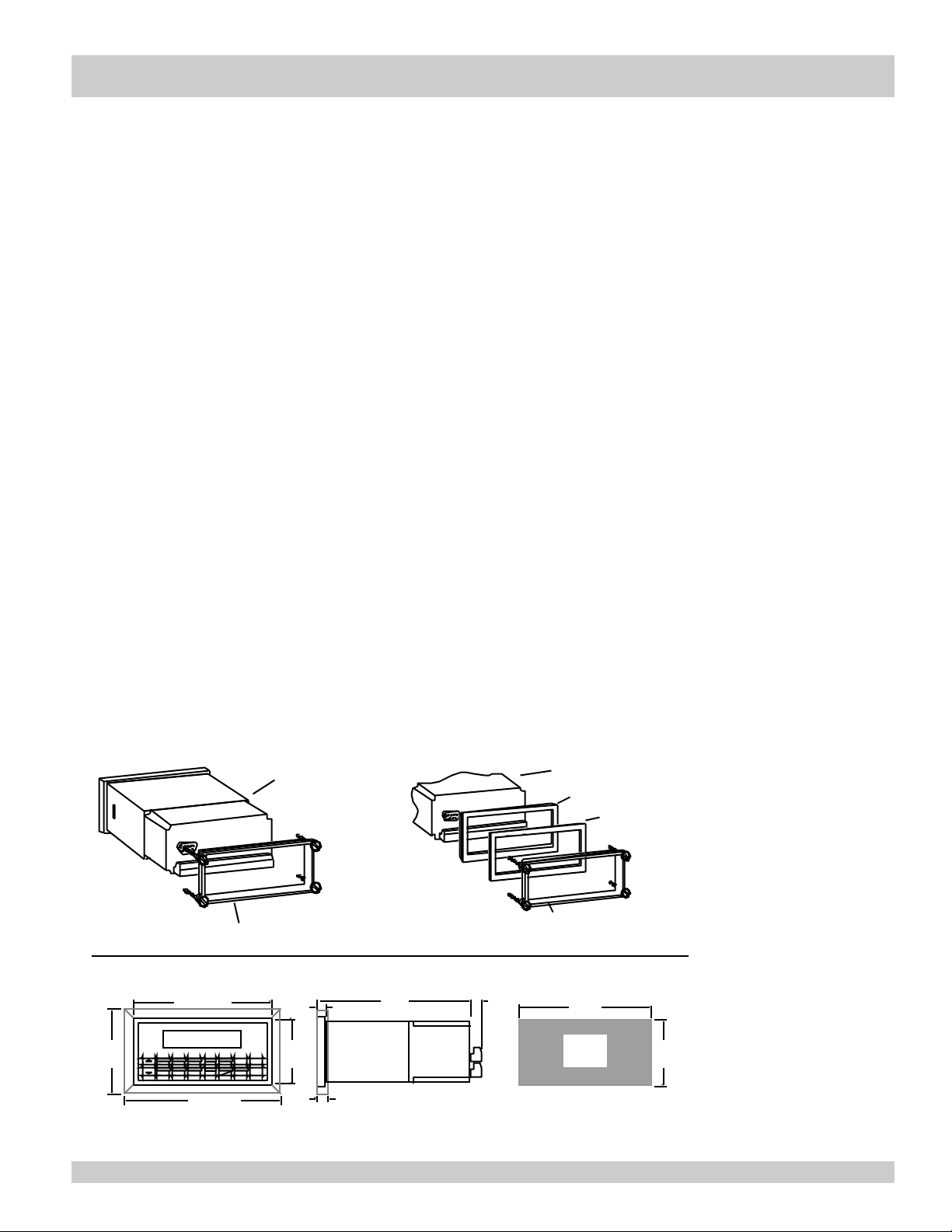
The 121 Series Flow Computer should be located in an area with a clean, dry
atmosphere which is relatively free of shock and vibration. The unit is installed in a
5.43" (138mm) wide by 2.68" (68mm) high panel cutout. (see Mounting Dimensions)
To mount the Flow Computer, proceed as follows:
Mounting Procedure:
a. Prepare the panel opening.
b. Slide the unit through the bezel adaptor and gasket.
c. Push the unit through the panel cutout until it touches the panel.
d. Install the screws (provided) in the mounting bracket and slip the bracket over
the rear of the case until it snaps in place.
e. Tighten the screws firmly to seat the bezel against the panel.
Termination Connectors:
Minimum Wire Gauge: 22 AWG
Maximum Wire Gauge: 14 AWG
Voltage/current limits are limited by unit specifications.
Permanently Connected Equipment:
UL 3101-1, Section 6.12.2.1 specifies that:
• A switch or circuit breaker shall be included in the building installation;
• It shall be in close proximity to the equipment and within easy reach of the
OPERATOR;
• It shall be marked as the disconnecting device for the equipment.
Ensure that the switch or circuit breaker chosen is suitable for the power
requirements of the unit.
2.2 Mounting Diagrams:
121 Series
Mounting Bracket
Dimensions
RATE
3.43
(87)
TOTAL 267395.749
1
START
GRAND6SCROLL7PRE 28DENS
STOP
121 Series
Mounting Bracket
5.67 (144)
GPM
147.43
GAL
TEMP4PRE 13RATE2TOTAL
PRINT
5
TIME
9
0
–
6.18
Dotted Line Shows Optional Bezel Kit
CLEAR•MENU
HELP
2.83
(72)
ENTER
0.28 (7.2)
0.4 (10)
6.15
(156)
0.5
(13)
Bezel Adaptor
Gasket
5.43
(138)
Panel
Cutout
2.68
(68)
Page 10

Applications
3. Applications
3.1 Liquid Volume
Measurements:
A flowmeter measures the actual volume in a liquid line. Atemperature sensor can also be installed to correct
for liquid thermal expansion (see 3.2 Corrected Volume).
Calculations:
• For Flowmeters with Pulse Outputs, Volume flow is calculated using the flowmeter
frequency output and the user entered K-Factor.
• For Flowmeters with Analog Transmitters, Volume flow is calculated using the measured
flowmeter signal and the user entered scale settings.
Output Results:
• Display Results
Flow Rate, Resettable Total, Non-Resettable Total
• Analog Output
Rate or Total
• Pulse Output
Total
• Relay Outputs
Rate or Total Alarms
Applications:
The Flow Computer can monitor actual volume flow and total of any liquid. Flow alarms are provided via
relays and datalogging is available via analog (4-20mA) and serial outputs.
Liquid Volume
Illustration
Calculations
Pulse Input; Average K-Factor
Volume Flow = input frequency • time scale factor
K-Factor
Analog Input; Linear
Volume Flow = % input • Full Scale Flow
Pg 10 121-000-350 © 2001 Max Machinery, Inc.
Page 11

Corrected Liquid Volume
3.2 Corrected Liquid Volume
Measurements:
A flowmeter measures the actual volume in a liquid line. Atemperature sensor is installed to correct for liquid
thermal expansion.
Calculations:
• Corrected Volume is calculated using the flow and temperature inputs as well as the thermal expansion
coefficient stored in the flow computer. Use the "SET FLUID PROPERTIES" submenu to define reference
temperature and density values for standard conditions.
Output Results:
• Display Results
Flow Rate, Resettable Total, Non-Resettable Total, Temperature, Density
• Analog Output
Rate, Total, Temperature or Density
• Pulse Output
Total
• Relay Outputs
Rate , Total or Temperature Alarms
Applications:
Monitoring corrected volume flow and total of any liquid. Flow alarms are provided via relays and datalogging
is available via analog (4-20mA) and serial outputs.
Corrected
Liquid Volume
Illustration
Temp./Dens.
Transmitter
Calculations
Volume Flow
As calculated in section 3.1
Corrected Volume Flow (Temp. Transmitter)
Corrected Volume Flow = vol. flow • (1 - Therm.Exp.Coef. • (Tf-Tref))
121-000-350 © 2001 Max Machinery, Inc. Pg 11
2
Page 12

Liquid Mass
3.3 Liquid Mass
Measurements:
Actual volume is measured by the flow element (DP transmitter, Flowmeter). Temperature
is measured by the temperature transmitter.Adensity transmitter can be used for direct
density measurements.
Calculations:
• The density and mass flow are calculated using the reference density and the thermal expansion coefficient of
the liquid (see "SET FLUID PROPERTIES" submenu)
Output Results:
• Display Results
Flow Rate, Resettable Total, Non-Resettable Total, Temperature, Density
• Analog Output
Rate, Total, Temperature or Density
• Pulse Output
Total
• Relay Outputs
Rate, Total or Temperature Alarms
Applications:
Monitoring mass flow and total of any liquid. Flow alarms are provided via relays and datalogging is available
via analog (4-20mA) and serial outputs.
Liquid Mass
Illustration
Calculations
Temp./Dens.
Transmitter
Volume Flow
As calculated in section 3.1
Mass Flow
Mass Flow = volume flow • density
Pg 12 121-000-350 © 2001 Max Machinery, Inc.
Page 13

Batching
3.4 Batching
Measurements:
A flowmeter measures the actual volume in a liquid line. Atemperature sensor can also
be installed to correct for liquid thermal expansion (see 3.2 Corrected Volume).
Calculations:
• For Flowmeters with Pulse Outputs, Volume flow is calculated using the flowmeter frequency output and the
user entered K-Factor.
• For Flowmeters with Analog Transmitters, Volume flow is calculated using the measured flowmeter signal and
the user entered scale settings.
• Corrected Volume is calculated using the flow and temperature inputs as well as the
thermal expansion coefficient stored in the flow computer.
Output Results:
• Display Results
Flow Rate, Batch Total, Non-Resettable Total, Temperature, Density
• Analog Output
Rate, Total, Temperature or Density
• Pulse Output
Total
• Relay Outputs
Batch Total, Rate, or Temperature Alarms
Applications:
Batching and monitoring flow and total of any liquid. Batching is accomplished via
relays and datalogging is available via analog (4-20mA) and serial outputs.
Batching Illustration
Temp./Dens.
Transmitter
Calculations
Volume Flow
As calculated in section 3.1
Corrected Volume Flow (Temp. Transmitter)
Corrected Vol. Flow = volume flow • (1 - Therm.Exp.Coef. •(Tf-Tref))
121-000-350 © 2001 Max Machinery, Inc. Pg 13
2
Page 14

Wiring
4 WIRING
4.1 Typical Batcher Wiring:
Batcher Wiring
For Model 121-500
Indicators, please refer to
drawing #121-500-200, on
page 67, for interface cable
pin information
4.2 Typical Rate/Total Wiring:
Rate / Total Wiring
Pg 14 121-000-350 © 2001 Max Machinery, Inc.
Page 15

Unit Operation
5. UNIT OPERATION
5.1 Front Panel Operation Concept for Run Mode
The 121 Series is fully programmable through the front panel. Please review the following usage summary before
attempting to use the instrument.
HELP
On-line help is provided to assist the operator in using this product. The help is available during RUN and SETUP
modes simply by pressing the HELP key. The HELP key is used to enter decimals when entering numeric values.
FUNCTION KEYS
In the RUN mode, several keys have a special, direct access feature, to display an item of interest (i.e. RATE,
TOTAL, PRESET1, etc.). Press the key to view your choice. Press the SCROLL key to return to scrolling display.
CLEARING TOTALIZER
To clear the total, you must press the TOTALFunction Key 3 times. You will be asked to verify this action. The
operator will be prompted to enter password if the unit is locked. NOTE: In the Batcher Mode, simply press the
CLEAR key to reset the total (the batcher must be stopped or finished batching). It is not necessary to press the
TOTALFunction Key first.
CLEARING GRAND TOTAL
To clear the grand total, you must press the GRAND Function Key 3 times. You will be asked to verify this action.
The supervisor will be prompted to enter the supervisor password if the unit is locked.
PRESET KEYS
In the RUN mode, PRESET 1 & PRESET 2 keys are used to view and/or change the preset setpoints. To view the
Presets,simply press the desired Preset key. Rapidly press the Preset keys 3 times, then press the Clear key for direct
editing of the preset setpoints.
SCROLL
Rapidly press the Scroll key twice to setup a display list. Press the CLEAR key to remove old scroll list. Press the
function key for the item you wish to add Use the arrow keys to assign the line.
PRINT
The PRINT key is used to print on demand. When the PRINT key is pressed, a user defined list of data (TOTAL,
RATE, PRESET1, etc.) is sent to the RS-232 port. A timed message of "PRINTING" will be displayed to
acknowledge the print request.
SPECIAL BATCHING KEYS
The START and STOP keys are used only when batching to start and stop batches. The CLEAR key will clear the
total without first pressing the TOTALkey (unit must be stopped). All other keys work the same in both Rate/Total
mode and Batch mode. The Start and Stop keys operation are set by the control input settings. The Start options are:
START or RESET/START. The Stop options are: STOP or STOP/RESET.
MENU KEY
The MENU key is used to enter the Setup and Test modes. Press the MENU key to enter the Setup and Test modes.
(See section 6 for Setup mode, section 8 for Test mode). The MENU key is used as "escape" in Setup and Test
Programming. Pressing the MENU key while programming in the Sub-Menu groups will backup the display to that
Sub-Menu group heading. Pressing the MENU key while viewing the Sub-Menu groups will backup the display to
the Top Level Menu.
ACKNOWLEDGING ALARMS
Most alarm messages are self-clearing. Press the ENTER key to acknowledge and clear alarms.
NOTE: Some keys and functions are password protected. Enter the password to gain access. The passwords are
factory set as follows:
Operator = 0
Supervisor = 2000
121-000-350 © 2001 Max Machinery, Inc. Pg 15
Page 16

General Operation
5.2 General Operation
The unit can display: Rate, Total, Grand Total, Temperature, Density, Presets and Time of Day. The Temperature
and/or Density can be displayed even if you are using the Volumetric Flow Equation (a Temperature or Density
sensor must be installed). The unit can perform Mass or Corrected Volume equations using a temperature or density
sensor (these equations can be computed without Temp/Dens sensors by using user defined default values). The
unit can be programmed to perform Ratemeter/Totalizer or Batching functions (see section 6.3, SELECT
INSTRUMENT Submenu).
5.3 Ratemeter/TotalizerOperation
The Ratemeter/Totalizer mode is used primarily to monitor flowrate and accumulated total. The relays can be
used to trigger flow, total, temperature or density alarms.
5.3.1 Password Protection for Rate/Total mode
After an Operator and/or Supervisor Password is entered in the setup mode (see section 6.3, SETUP PASSWORD
submenu), the unit will be locked. The unit will prompt the user for the password when trying to perform the
following functions:
Clear Total
Clear Grand Total
Enter Menu
Edit Preset 1
Edit Preset 2
The Supervisor password should be reserved for supervisors. The Supervisor password will allow access to
restricted areas of the Setup and Test menus.
5.3.2 Relay Operation in Rate/Total mode
Two relays are available for alarm outputs. The relays can be assigned to trip according to rate, total, temperature,
density readings or general system alarms. The relays can be programmed for low or high alarms. Preset 1(RLY1)
and Preset 2 (RLY2) are easily accessible by pressing the PRESET 1or PRESET 2 key on the front panel.
5.3.3 Pulse Output in Rate/Total mode
The isolated pulse output (open collector) is menu assignable to Volume Total, Corrected Volume Total or Mass
Total. The pulse output duration can be set for 10mS (50 Hz max) or 100mS (5 Hz max). A pulse output scale
factor (pulse value) can be set to scale the pulse output. The pulse output is ideal for connecting to remote
totalizers or other devices such as a PLC. See section 1.3 for electrical specifications.
5.3.4 Analog Output in Rate/Total mode
The analog output is menu assignable to correspond to the Volume Rate, Corrected Volume Rate, Mass Rate,
Temperature, Density, Volume Total, Corrected Volume Total or Mass Total. The analog output is ideal for "trend"
tracking using strip chart recorders or other devices.
5.3.5 RS-232 Serial Port Operation in Rate/Total mode
The RS-232 serial port can be used for programming (using the Setup Disk) or for communicating to printers and
computers in the Operating Mode (Run Mode).
PC Communications:
The Setup Disk also allows the user to query the unit for operating status such as Flow Rate, Flow Total,
Temperature, Density, Presets, etc.
Pg 16 121-000-350 © 2001 Max Machinery, Inc.
Page 17

General Operation
Operation of RS-232 Serial Port with Printers:
Transaction Printing
For transaction printing, the user defines the items to be included in the printed document
(see section 6.3.20 SET DATA OUTPUT, Select_list). The transaction document can be initiated by pressing the
PRINT key or by a remote contact closure.
Data Logging
In data logging, the user defines the items to be included in each data log (see section 6.3.20 SET PRINTER
OUTPUT, Select_list). The user can also select when (time of day) or how often (print interval) the data log is to
be made (see section 6.3.19 SET PRINTER OUTPUT, Configure).
System Setup and Maintenance Report
The system setup and maintenance report lists all of the instrument setup parameters and usage for the current
instrument configuration. The audit trail information and a status report is also printed. This report is initiated in
the Test menu (see section 8.2.3 PRINT SYSTEM SETUP).
5.4 Batcher Operation
The Batcher mode is used primarily to control batches. The main difference between the Batch mode and
Rate/Total mode is the relay operation. The Batch mode allows the operator to "START" the unit via the front
panel or remote input. Once started, the relays (RLY1 & RLY2) will energize and send power to a flow control
device (i.e. solenoid valve or pump). The flow sensor will send a signal to the unit and total accumulation will
begin. When the Prewarn value (PRESET 2) is reached, Relay 2 will drop out (this is ideal for flow slow down).
When the Batch amount (PRESET 1) is reached,Relay 1 will drop out and the Batch is complete.
Several messages will be displayed during normal batch operation (i.e. Batch Fill, Batch Stopped). The keypad is
disabled for the duration of these timed messages (approx. 2 sec).
5.4.1 Batcher Configuration.
When the unit is programmed for batch mode, several batch operation choices are
available. These choices include: Up or Down Counting, Maximum Batch Preset, Batch
Overrun Compensation, Auto Batch Restart, Time Delay, Flow Signal Timeout, Maximum
Drain Time, Slow Start Quantity, Start or Reset/Start, and Stop or Stop/Reset.
Batch Count Mode
The Batch Count Mode allows the user to choose whether the unit will batch up to a
preset value or batch down from a preset value to zero.
Maximum Batch Preset
The Maximum Batch Preset allows the user to program the Maximum Batch value allowed to be entered by the
operator. If an operator should try to program a batch higher then this value, the unit will not allow the value to
be entered and will prompt the user with an error message saying that the Maximum Batch Preset has been
exceeded.
Batch Overrun
The Batch Overrun is used for batch applications that have slow responding valves and a consistent batching
flowrate. When the Batch Overrun is set, the unit will compensate for batch overruns by computing an averaged
overrun value from the last four batches. This average is used to internally adjust the batch setpoint to minimize
overrun.
Auto Batch Restart
The Auto Batch Restart function allows the user to set an amount of time to automatically restart a batch after the
completion of a batch (choose on or off).
121-000-350 © 2001 Max Machinery, Inc. Pg 17
Page 18

General Operation
Time Delay
The Time Delay for Auto Batch Restart functions as follows: When a batch is completed, the next batch will
automatically start after the amount of time entered here. This time can be set from 1 to 99 seconds.
Flow Signal Timeout
The Flow Signal Timeout allows the user to enter a timeout of 0 to 99 seconds. If a batch is “Filling” and zero
flow persists for more than the user entered time then the batch will be aborted. This prevents over flows due to
faulty flow sensors and/or wiring.
Maximum Drain Time
The unit declares that a batch is “done” when the flow rate equals “0”. A flow rate may be present long after the
Preset Relay de-energizes due to slow reacting valves or leaky valves. The Maximum Drain Time allows the
user to enter an amount of time (0 to 99 seconds) to wait before declaring “Batch Done”. After the Preset Batch
quantity is reached, the unit will declare “Batch Done” when the flow rate is “0” or the Maximum Drain Time
has expired. The batch data will then be available for printing and datalogging.
Slow Start Quantity
The Slow Start Quantity is a function that allows an amount to be entered for a Slow Start up. This function
requires two stage valve control. RLY 1 (slow flow) will energize for Slow Start and RLY 2 (fast flow) will
energize after the Slow Start Quantity has been delivered. This helps reduce turbulence when filling an empty
container.
START, RESET/START and STOP, STOP/RESET
When configuring the control inputs, Control Input1 can be set for START or RESET/START. When set for
START, the unit will start batching when a signal is applied to Control Input1 or the front panel Start key is
pressed. A separate Reset signal must be used to clear the previous batch total. When set for RESET/START, the
unit will automatically reset then start when a signal is applied to Control Input1 or the front panel Start key is
pressed (provided that the pervious batch was completed). If a previous batch was stopped during a batch cycle,
the unit will Start from where it was stopped. Control Input 2 can be set for STOP or STOP/RESET. When set
for STOP, the unit will stop batching when a signal is applied to Control Input 2 or the front panel Stop key is
pressed. A separate Reset signal must be used to clear the batch total. When set for STOP/RESET, a running
batch will stop when a signal is applied to Control Input 2 or the front panel Stop key is pressed. If the unit is
Stopped or after a completed batch, the unit will reset when a signal is applied to Control Input 2 or the front
panel Stop key is pressed. NOTE: Applying a voltage level to Control Input 2 will inhibit all Start inputs in
either mode.
5.4.2 Password Protection for Batcher Mode
After an Operator and/or Supervisor Password is entered in the setup mode (see section 6.3, SETUP PASS
WORD submenu), the unit will be locked. The unit will prompt the user for the password when trying to per
form the following functions:
Clear Grand Total
Enter Menu
The Supervisor password should be reserved for supervisors. The Supervisor password will allow access to
restricted areas of the Setup and Test menus. The passwords are factory set as follows:
Operator = 0
Supervisor = 2000
5.4.3 Relay Operation in Batcher mode
Two relays are available for alarm outputs. Preset 1 (RLY1) is reserved for batch amount, Preset 2 (RLY2) is
reserved for prewarn. (see section 5.4 Batcher Operation for Relay 1 & Relay 2 functions) Preset 1 (RLY1) and
Preset 2 (RLY2) are easily accessible by pressing the PRESET 1 or PRESET 2 key on the front panel.
Pg 18 121-000-350 © 2001 Max Machinery, Inc.
Page 19

General Operations
5.4.4 Pulse Output in Batcher mode
The isolated pulse output (open collector) is menu assignable to Volume Total, Corrected Volume Total or Mass
Total. The pulse output duration can be set for 10mS (50 Hz max) or 100mS (5 Hz max). A pulse output scale
factor (pulse value) can be set to scale the pulse output. The pulse output is ideal for connecting to remote
totalizers or other devices such as a PLC. See section 1.3 for electrical specifications.
5.4.5 Analog Output in Batcher mode
The analog output is menu assignable to correspond to the Volume Rate, Corrected Volume Rate, Mass Rate,
Temperature, Density, Volume Total, Corrected Volume Total or Mass Total. The analog output is ideal for
"trend" tracking using strip chart recorders or other devices.
5.4.6 RS-232 Serial Port Operation in Batcher mode
The RS-232 serial port can be used for programming (using the Setup Disk) or for communicating to printers
and computers in the Operating Mode (Run Mode).
PC Communications:
The Setup Disk also allows the user to query the unit for operating status such as
Flow Rate, Flow Total, Temperature, Density, Presets, etc.
Operation of RS-232 Serial Port with Printers:
Transaction Printing
For transaction printing, the user defines the items to be included in the printed document (see section 6.3.20
SET DATAOUTPUT, Select_list). The transaction document can be initiated by pressing the PRINT key, by a
remote contact closure or print at end of batch.
Data Logging
In data logging, the user defines the items to be included in each data log (see section 6.3.20 SET PRINTER
OUTPUT, Select_list). The user can also select when (time of day) or how often (print interval) the data log is
to be made (see section 6.3.19 SET PRINTER OUTPUT, Configure).
System Setup and Maintenance Report
The system setup and maintenance report lists all of the instrument setup parameters and usage for the current
instrument configuration. The audit trail information and a status report is also printed. This report is initiated in
the Test menu (see section 8.2.3 PRINT SYSTEM SETUP).
121-000-350 © 2001 Max Machinery, Inc. Pg 19
Page 20

General Operations
6. PROGRAMMING
6.1 Front Panel Operation Concept for Program Mode
The 121 Series may be fully programmable through the front panel. Please review the following usage summary
before attempting to use the instrument.
Setup Mode:
MODE CHANGES
Pressing the MENU key will offer selections of RUN, SETUP, TEST. RUN is the normal operating mode for
the instrument. SETUP offers various sub-menus used for instrument setup. TEST offers various sub-menus for
Test, Calibration and System Start-up.
Submenu GROUP NAVIGATION
Use the UP and DOWN arrow keys to navigate up and down through the Sub-Menu groups when in the SETUP
or TEST mode. Press the ENTER key to enter a desired setup or test Sub-Menu group.
SELECTION OF ITEM
During setup, the unit will often offer multiple choices for a given topic. The topic prompt appears on the top
line of the display. The choices are shown on the lower line of the display.
To select an item, press the key beneath the desired choice. The selected choice will blink. Press the
ENTER key to accept the selected choice.
NUMERIC ENTRY
The keys labeled "0 - 9", "–", ".", CLEAR and ENTER are used to enter numerical values. A leading 0 will
assume that you intend to enter a minus "–" sign. Press the CLEAR key to clear the existing value and to
enable editing.
TEXT CHARACTER ENTRY
Some setup items (i.e. Descriptors, Units Label) require the user to enter text characters. Press CLEAR to
enable editing. The UP and DOWN arrow keys are used to scroll through the available character sets for each
individual character. Press the ENTER key to accept the character and advance to the next character.
Pg 20 121-000-350 © 2001 Max Machinery, Inc.
Page 21
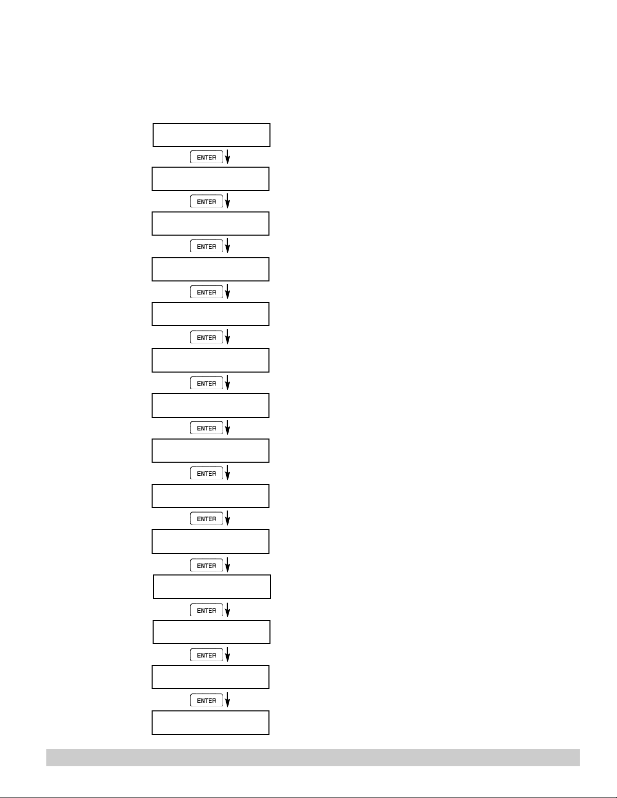
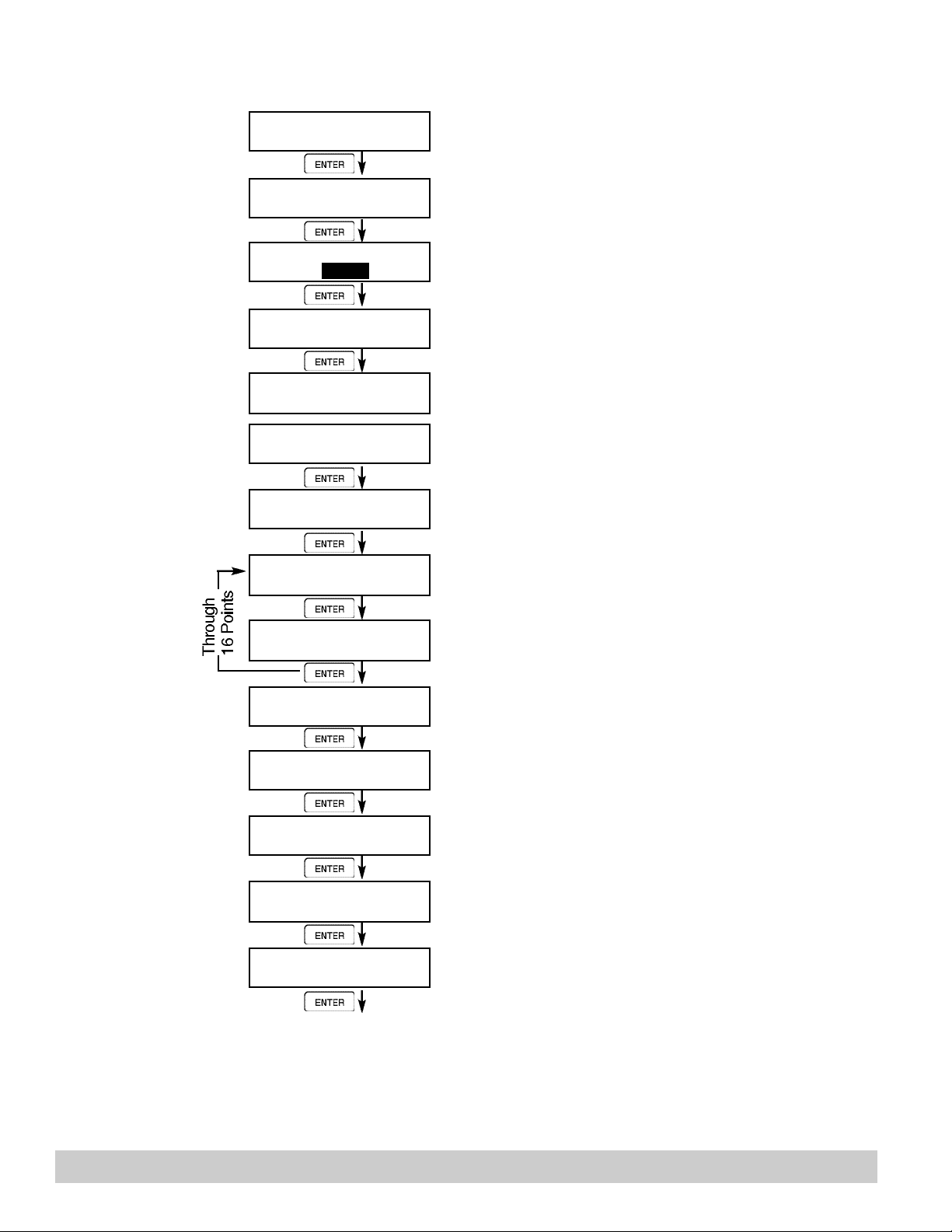
6.2 EZ Setup
121-000-350 © 2001 Max Machinery, Inc. Pg 21
The EZ Setup routine is a quick and easy way to configure the unit for the most commonly used instrument
functions. This setup assumes that you are measuring Volumetric Flow. Entering the EZ Setup mode
automatically sets many features. This may cause any previously programmed information to be lost or reset.
For a complete customized configuration, see sections 6.3 and 6.4.
6.2.1
TOP LEVEL
SETUP MENU
6.2.2
EZ Setup
Submenu
Groups
SELECT OPERATE STATE
Run Setup Test
SELECT EZ SETUP
ARE YOU SURE?
No Yes
INSTRUMENT TYPE
Rate/Tot Batch
RATE time base
Sec Min Hour Day
RATE Dec places
0
TOTALVOLUME UNITS
gal
Select Setup to enter the instrument setup routine.
Press ENTER to begin EZ Setup routine.
Confirm that you want to run EZ Setup. Caution:
Any previous program settings may be lost or
reset.
Instrument Type.
Select the appropriate rate time base.
Enter the desired rate decimal location.
0-3 decimal places allowed.
Enter the desired totalizer units label.
TOTALDec places
0
K_FACTOR TYPE
Avg LinTbl UVC
AVERAGE KA-FACTOR
####### P/gal
LINEAR TABLE KA
Fre01:######## Hz
LINEAR TABLE KA
KA--01:##########
FS ANALOG OUT 20mA
#######gal/m
RATE 00.0 gal/m
TOTAL 0 gal
Enter the desired totalizer decimal location. 0-3
decimal places allowed.
Enter the desired K-Factor Type.
If Average selected, Enter the desired Average KFactor.
If LinTbl or UVC selected,
Enter the desired frequency/ K-Factor pair for
each point in the Linearization Table. (up to 16 pairs)
Enter a frequency of 0 for any point other than
Fre01 to exit Linearization Table setup.
Enter the desired full scale setting for the analog
output.
Return to Run Mode
Page 22
TOP LEVEL
Pg 22 121-000-350 © 2001 Max Machinery, Inc.
SETUP MENU
6.3.2
EZ Setup
Submenu
Groups
START
SELECT OPERATE STATE
Run Setup Test
MENU
ENTER
SELECT EZ SETUP
STOP
START
INSTRUMENT TYPE
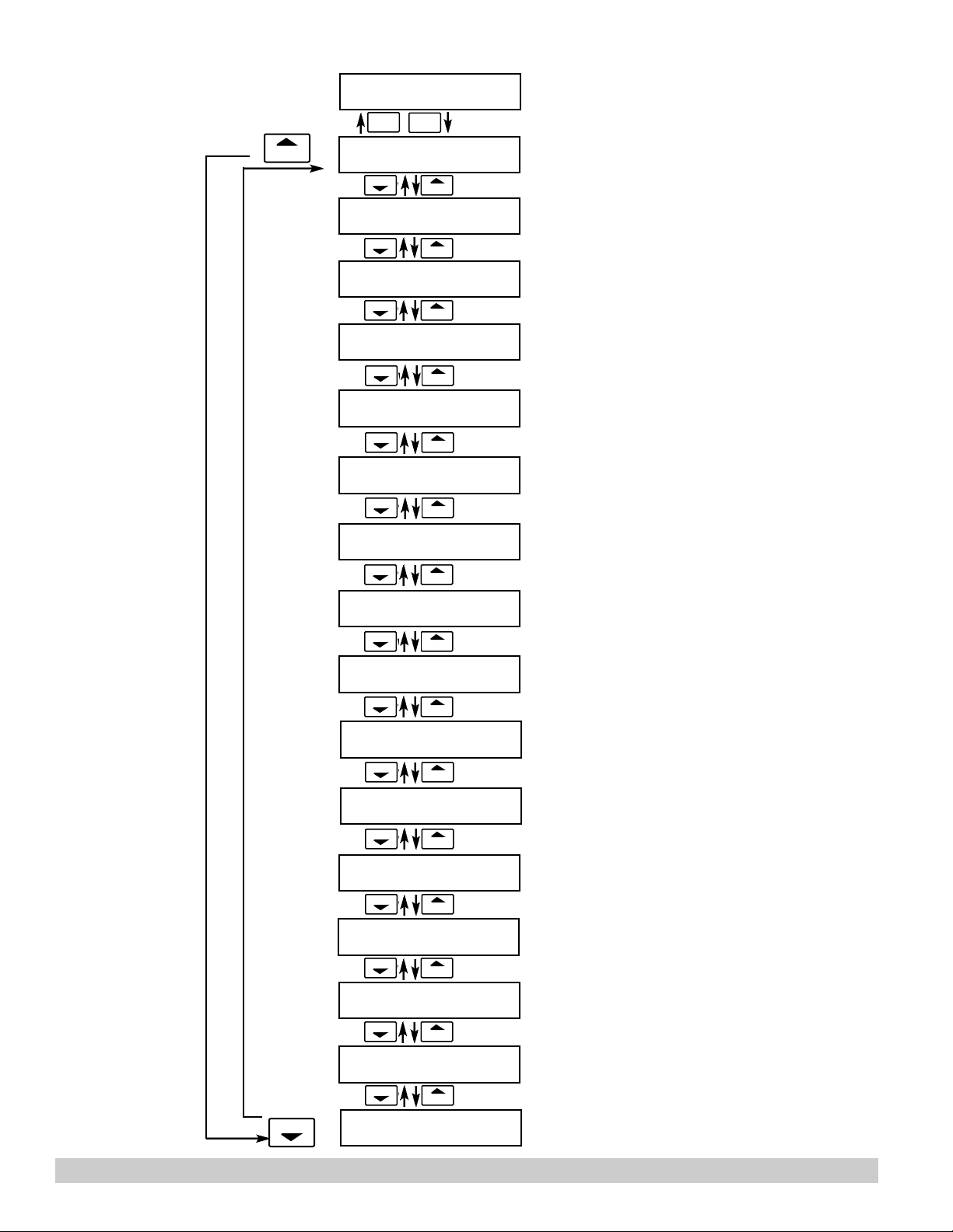
Select Setup to enter the instrument setup
routine.
Refer to Page 21 for Details.
Refer to Page 23 for Details.
STOP
START
SELECT FLOW EQUATION
STOP
START
SETUP INDICATORS
STOP
START
SETUP FLOW INPUT
STOP
START
SETUPAUX INPUT
STOP
START
SET FLUID PROPERTIES
STOP
START
SETUP PULSE OUTPUT
STOP
START
SETUPANALOG OUTPUT
Refer to Pages 24 for Details.
Refer to Page 24 & 25 for Details.
Refer to Page 26, 27 & 28 for Details.
Refer to Pages 29 for Details.
Refer to Page 30 for Details.
Refer to Pages 30 for Details.
Refer to Page 31 for Details.
STOP
STOP
START
SETUP RELAYS
STOP
START
SETUP CONTROL INPUTS
STOP
START
SETUP REALTIME CLOCK
STOP
START
SERIAL USAGE
STOP
START
SETUP DATALOG/PRINT
STOP
START
ADMINISTRATIVE SETUP
STOP
START
SETUP NETWORK CARD
Refer to Page 31 & 32 for Details.
Refer to Page 33 for Details.
Refer to Page 34 for Details.
Refer to Page 35 for Details.
Refer to Pages 36 & 37 for Details.
Refer to Page 37 for Details.
Refer to Page 38 for Details.
Page 23
STOP
STOP
STOP
STOP
STOP
STOP
121-000-350 © 2001 Max Machinery, Inc. Pg 23
STOP
SELECT EZ SETUP
Advance To
INSTRUMENT TYPE
INSTRUMENT TYPE
INSTRUMENT TYPE
Rate/Tot Batch
Advance To
SELECT FLOW EQUATION
INSTRUMENT TYPE
INSTRUMENT TYPE
Rate/Tot Batch
BATCH COUNT MODE
Up Down
MAXIMUM BATCH PRESET
1000.0 gal
BATCH OVERRUN COMP
Off On
AUTO BATCH RESTART
Off On
TIME DELAY (1-99sec)
10
FLOW SIGNAL TIMEOUT
10
MAXIMUM DRAIN TIME
10
SLOW START QUANTITY
10
Advance To
SELECT FLOW EQUATION
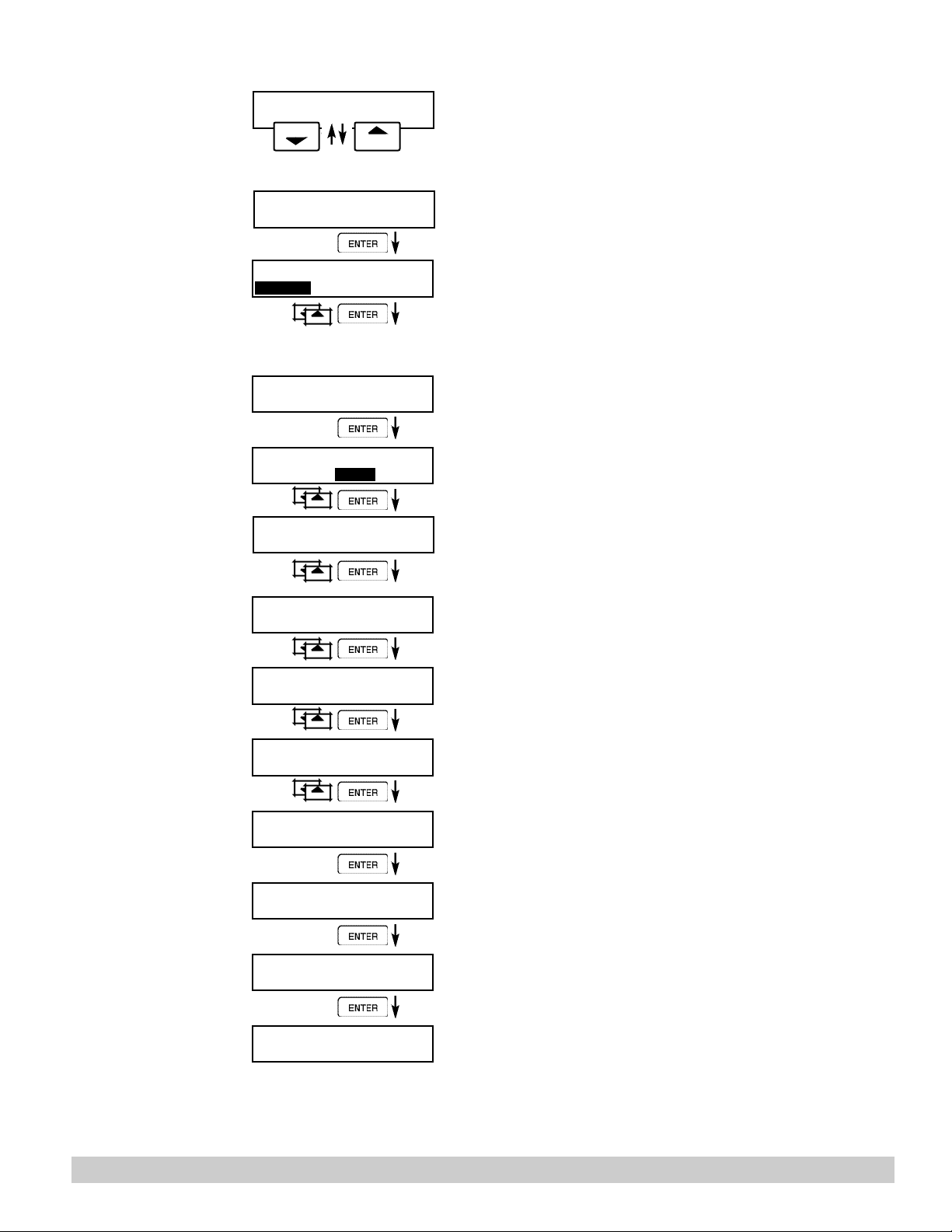
Refer to page 21 for EZ Setup routine.
Press the DOWN (stop) key to advance to
Instrument Type. Press the UP (start) key to
advance to Administrative Setup.
Press ENTER to enter Instrument Type submenus.
Press ENTER when Rate/Total is flashing to
configure the instrument as a
Ratemeter/Totalizer.
If Rate/Tot selected, advance to Select Flow
Equation.
Press ENTER to enter Instrument Type submenus.
Press ENTER when Batch is flashing to configure the instrument as a Batcher.
Select UP to Reset to 0 and count up to preset.
Select DOWN to reset to Preset and count
down to 0.
Enter the maximum allowable Batch Preset. The
operator will not be able to enter a batch preset
larger than this value.
Select ON to set the unit to operate using a
Batch Overrun Compensation routine.
Select OFF to inhibit Batch Overrun
Compensation routine. (See Section 5.4)
Select On to enable the Auto Batch Restart.
This will automatically restart the unit at the end
of each batch run. Select Off if this is not desirable.
Enter Time Delay for Auto Batch Restart. When
a batch is completed, the next batch will start
after the amount of time entered here.
Enter a timeout of 0 to 99 seconds. If a batch is
“Filling” and zero flow persists for more than this
time, the batch will be aborted.
Enter time (0-99 sec.) for Max. Drain Time. After
batch quantity is reached, “Batch Done” is
declared when the flow rate is “0” or the
Maximum Drain Time has expired.
Enter a quantity for a Slow Start up. RLY 2
(slow flow) will energize for Slow Start and RLY
1 (fast flow) will energize after the Slow Start
Quantity has been delivered.
START
START
START
START
START
START
START
Page 24
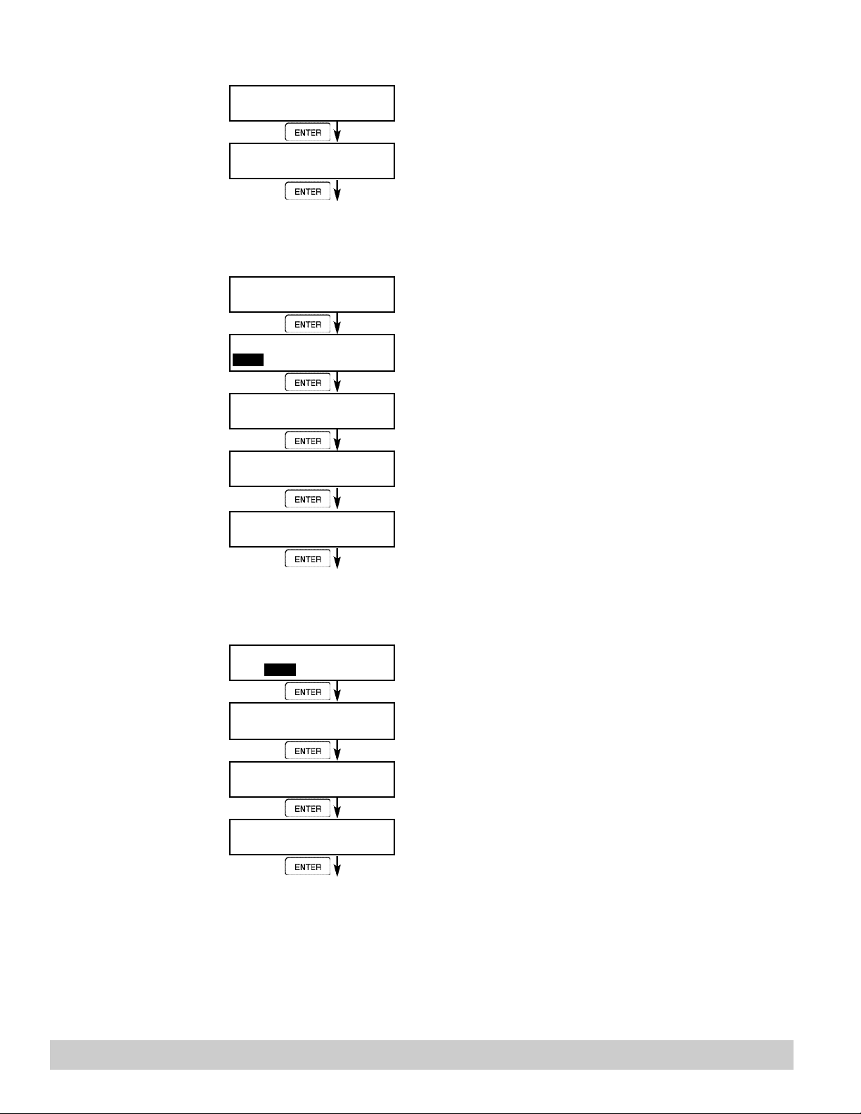
6.4.3
SELECT
FLOW EQUATION
S E L E C T FLOW EQUAT I O N
ENTER
S E L E C T FLOW EQUATION
Volume Mass Cor/Vol
ENTER
Advance To
SETUP INDICATORS (Total)
Press ENTER to enter Select Flow Equation submenus.
Press ENTER when desired flow equation is
flashing.
6.4.4
SETUP
INDICATORS
(Total)
6.4.5
SETUP
INDICATORS
(Density)
SETUP INDICATORS
ENTER
SETUP INDICATORS
Total Dens Rate Temp
ENTER
TOTALDESCRIPTOR
TOTAL
ENTER
TOTALVOLUME UNITS
gal
ENTER
TOTALDEC PLACES
0
ENTER
Advance To
SETUP INDICATORS
(Density)
SETUP INDICATORS
Total Dens Rate Temp
ENTER
DENSITY DESCRIPTOR
DENS
ENTER
DENSITY MASS UNITS
lbs
ENTER
DENSITY DEC PLACES
0
ENTER
Press ENTER to begin setup of the Indicators
Press ENTER when Total is flashing to configure
the Totalizer Indicators
Enter the desired Total Descriptor
Enter the desired Volume Units Label for the
Totalizer.
Select the desired Total Decimal Place.
0-3 decimal places allowed.
Press ENTER when Dens is flashing to configure
the Density Indicators.
Enter the desired Density Descriptor.
Enter the desired Mass Units Label for Density.
Select the desired Density Decimal Place.
0-3 decimal places allowed.
Advance To
SETUP INDICATORS
(Rate)
Pg 24 121-000-350 © 2001 Max Machinery, Inc.
Page 25
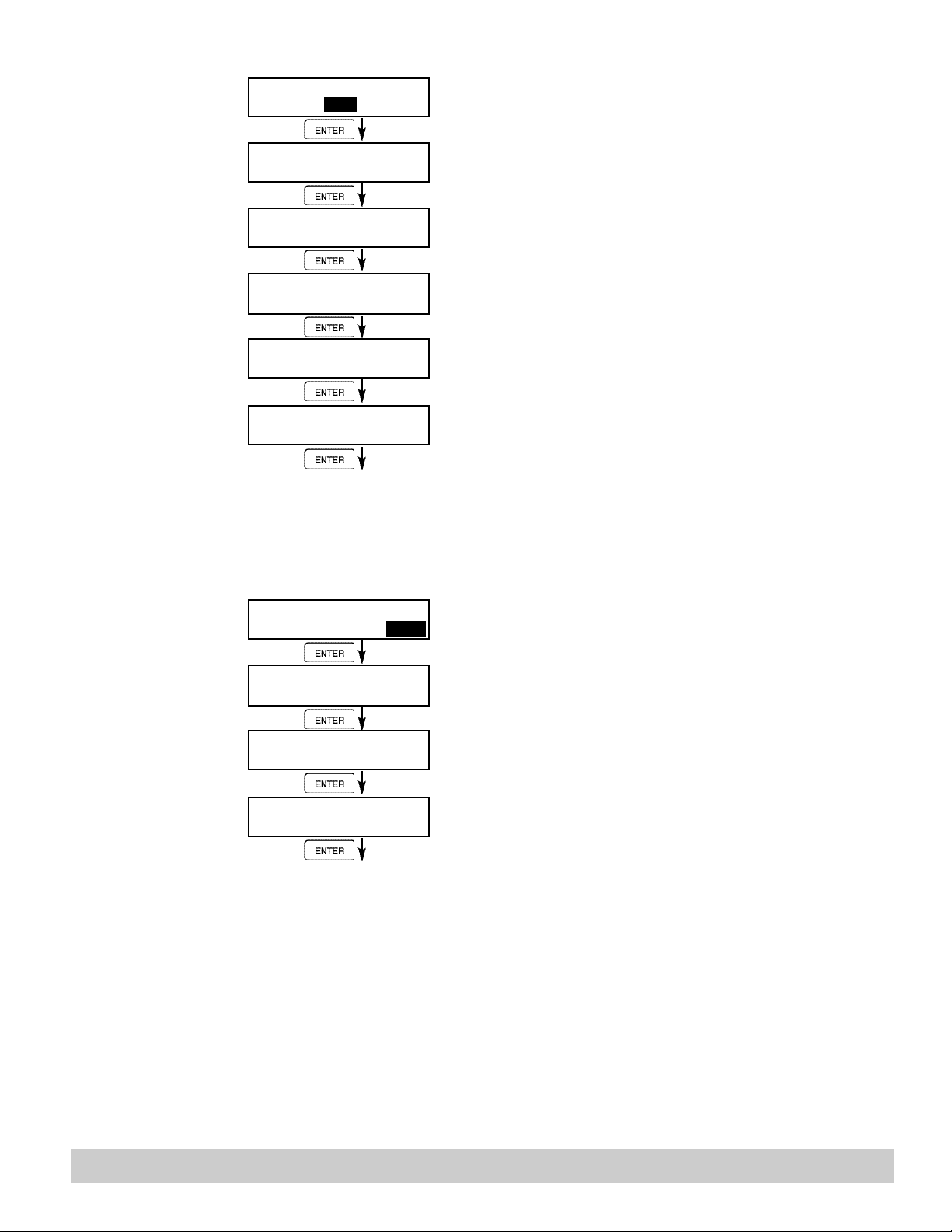
6.4.6
SETUP
INDICATORS
(Rate)
6.4.7
SETUP
INDICATORS
(Temperature)
Press ENTER when Rate is flashing to configure the Ratemeter Indicators
Select the desired Rate Time Base.
Enter the desired Descriptor for the Ratemeter.
Select the desired Rate Decimal Place.
0-3 decimal places allowed.
Enter desired Rate Averaging Filter.
Enter desired Percent of Change for Quick
Update. If the current flowrate deviates by an
amount greater than the percentage value
entered, the Rate Averaging is inhibited.
(See Page 62 for more details.)
Press ENTER when Temp is flashing to configure the Temperature Indicators.
Enter the desired Temperature Descriptor.
Enter the desired Temperature Scale.
Select the desired Temperature Decimal Place.
0-3 decimal places allowed.
SETUP INDICATORS
Total Dens Rate Temp
ENTER
RATE time base
Sec Min Hour Day
ENTER
RATE DESCRIPTOR
RATE
ENTER
RATE Dec places
ENTER
RATE Avg filter
ENTER
QUICK UPDATE %
ENTER
Advance To
SETUP INDICATORS
(Temperature)
0
0
5
SETUP INDICATORS
Total Dens Rate Temp
ENTER
TEMP DESCRIPTOR
TEMP
ENTER
TEMPERATURE SCALE
Deg_C Deg_F
ENTER
TEMP Dec places
0
ENTER
Advance To
SETUP FLOW INPUT
121-000-350 © 2001 Max Machinery, Inc. Pg 25
Page 26
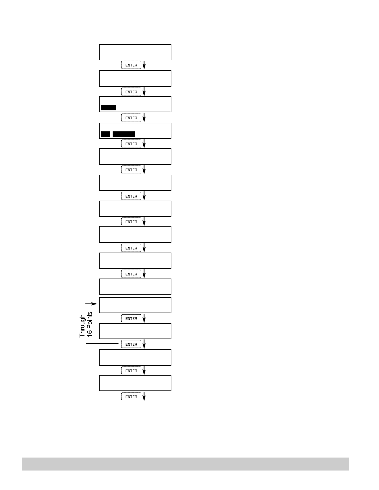
6.4.8
SETUP
FLOW INPUT
(Pulse - Ain & PS
(A=B))
NOTE:
Ain = Single Pulse
PS(A=B) = Pulse
Security
Qx1 = Quadrature
Qx2 = Quadrature x 2
SETUP FLOW INPUT
ENTER
EXCITATION VOLTAGE
5v 12v 24v
ENTER
FLOW INPUT TYPE
Pulse Analog
ENTER
PULSE INPUT TYPE
Ain PS(A=B) Qx1 Qx2
ENTER
PULSE TRIGGER LEVEL
10mV 100mV 2.5V
ENTER
LOW PASS FILTER
40Hz 3KHz 20KHz
ENTER
INPUT TERMINATION
Pullup Pulldown None
ENTER
MAX WINDOW (1-99)
1
ENTER
K_FACTOR TYPE
Avg LinTbl UVC
ENTER
AVERAGE KA-FACTOR
####### P/gal
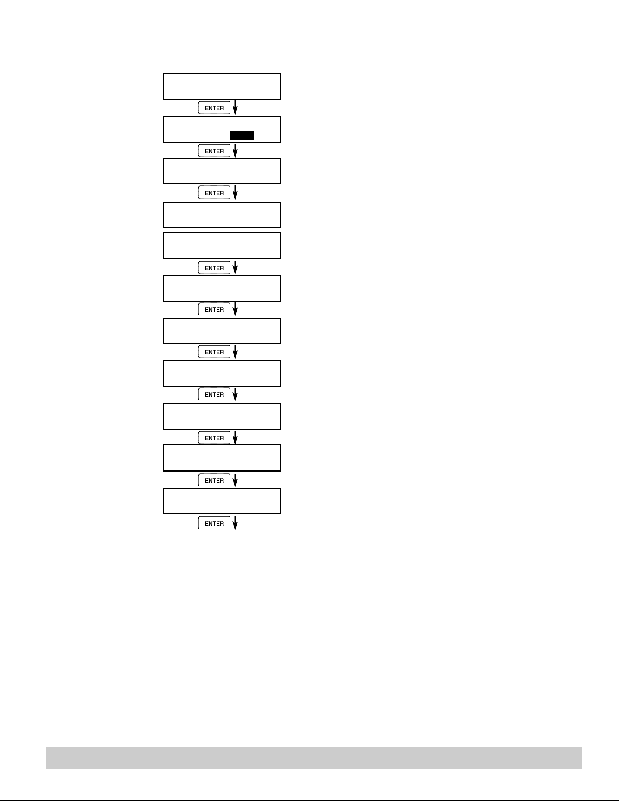
Press ENTER to begin setup of Flow Input.
Select the desired Excitation Voltage.
Press ENTER when Pulse is flashing to configure
the flow input for Pulse signals.
Enter the desired Pulse type. See side note.
Select the desired Input Pulse Trigger Level.
Select the desired Low Pass Filter.
(Max. Count Speed).
Select the proper input termination.
Enter the desired Maximum Sample Window Time
(1-99 sec).
Enter the desired K-Factor Type.
If Avg selected, Enter the desired Average K-Factor.
LINEAR TABLE KA
Fre01:######## Hz
ENTER
If LinTbl selected,
Enter the desired frequency/ K-Factor pair for each
point in the Linearization Table.
NOTE: Enter 0 for Fre value of any point (other than
LINEAR TABLE KA
KA--01:####### P/gal
ENTER
LOW FLOW RATE ALARM
####### gal/m
ENTER
HIGH FLOW RATE ALARM
####### gal/m
ENTER
Advance To
SETUP AUX INPUTS
Enter the desired volumetric Low Rate Alarm.
This will trigger an alarm message if alarm conditions occur. The relays are not affected.
Enter the desired volumetric High Rate Alarm.
This will trigger an alarm message if alarm conditions occur. The relays are not affected.
Fre01) to exit the routine and use the values
entered up to that point.
Pg 26 121-000-350 © 2001 Max Machinery, Inc.
Page 27
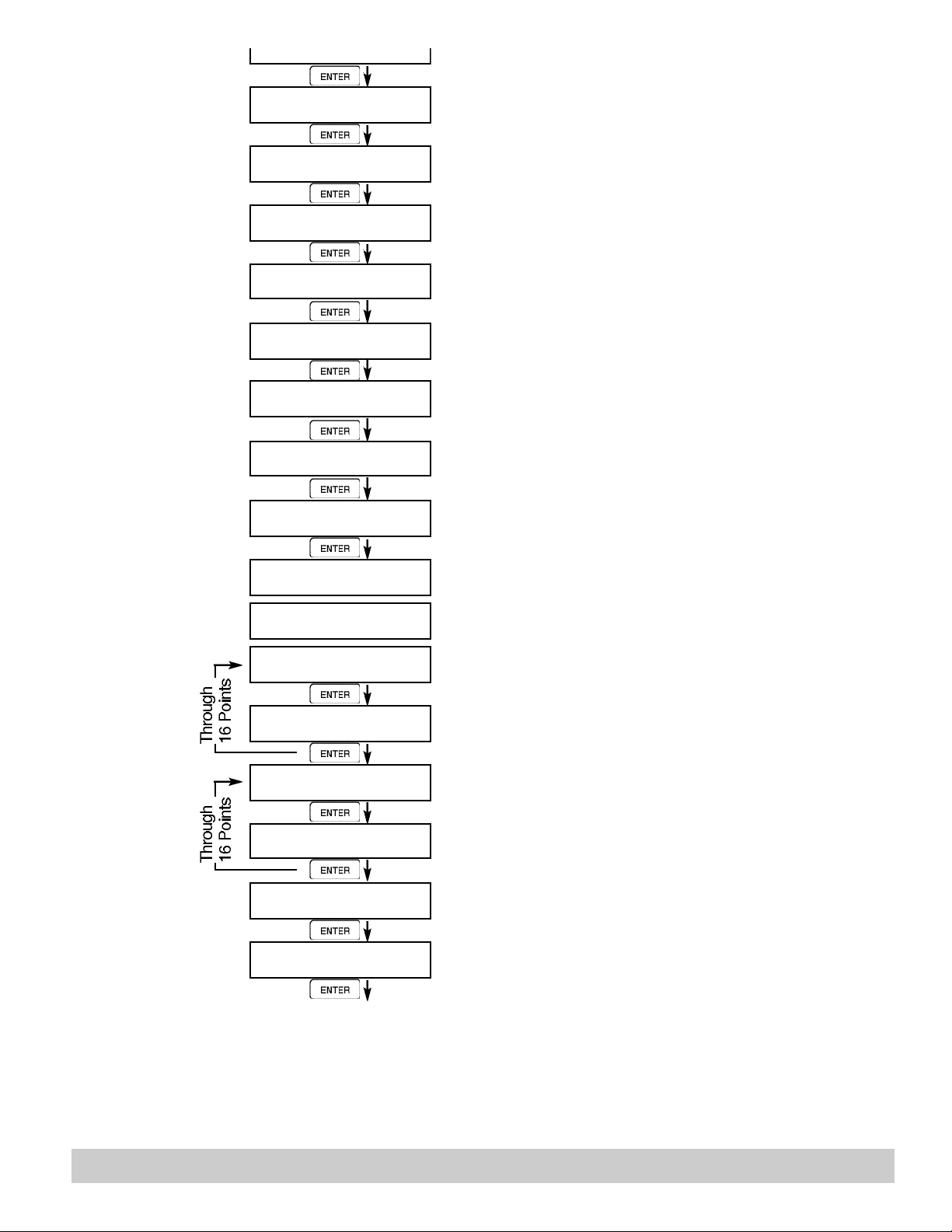
SETUP
FLOW INPUT
(Pulse - Quadrature,
Qx1 or Qx2)
NOTE:
Ain = Single Pulse
PS(A=B) = Pulse
Security
Qx1 = Quadrature
Qx2 = Quadrature x 2
Select the desired Excitation Voltage.
Press ENTER when Pulse is flashing to configure the
flow input for Pulse signals.
Enter the desired Pulse type. See side note.
Select the desired Input Pulse Trigger Level.
Select the desired Low Pass Filter.
(Max. Count Speed).
Select the proper input termination.
Enter the desired Maximum Sample Window Time (1-999
in 1/10 sec increments).
Enter the desired K-Factor Type.
If Avg selected, Enter the desired Average K-Factor (KA
for channel A).
Enter the desired Average K-Factor (KB for channel B).
If LinTbl selected,
Enter the desired frequency/ K-Factor pair for each point
in the Linearization Table. (channel A)
NOTE: Enter 0 for Fre value of any point
(other than Fre01) to exit the routine
and use the values entered up to that point.
Enter the desired frequency/ K-Factor pair for each point
in the Linearization Table. (channel B)
NOTE: Enter 0 for Fre value of any point (other than
Fre01) to exit the routine and use the values entered up
to that point.
Enter the desired volumetric Low Rate Alarm.
This will trigger an alarm message if alarm conditions
occur. The relays are not affected.
Enter the desired volumetric High Rate Alarm.
This will trigger an alarm message if alarm conditions
occur. The relays are not affected.
EXCITATION VOLTAGE
5v 12v 24v
FLOW INPUT TYPE
Pulse Analog
PULSE INPUT TYPE
Ain PS(A=B) Qx1 Qx2
PULSE TRIGGER LEVEL
10mV 100mV 2.5V
LOW PASS FILTER
40Hz 3KHz 20KHz
INPUT TERMINATION
Pullup Pulldown None
MAX WINDOW (1-999) 1/10 sec.
20
K_FACTOR TYPE
Avg LinTbl UVC
AVERAGE KA-FACTOR
####### P/gal
AVERAGE KB-FACTOR
####### P/gal
LINEAR TABLE KA
Fre01:######## Hz
LINEAR TABLE KA
KA--01:####### P/gal
LINEAR TABLE KB
Fre01:######## Hz
LINEAR TABLE KB
KA--01:####### P/gal
LOW FLOW RATE ALARM
####### gal/m
HIGH FLOW RATE ALARM
####### gal/m
Advance To
SETUP AUX INPUTS
121-000-350 © 2001 Max Machinery, Inc. Pg 27
Page 28
ENTER
6.4.10
SETUP
FLOW INPUT
(Analog)
SETUP FLOW INPUTS
ENTER
EXCITATION VOLTAGE
5v 12v 24v
ENTER
FLOW INPUT TYPE
Pulse Analog
ENTER
ANALOG SIGNAL TYPE
Voltage Current
ENTER
ANALOG VOLTAGE RANGE
0-10V 0-5V 1-5V
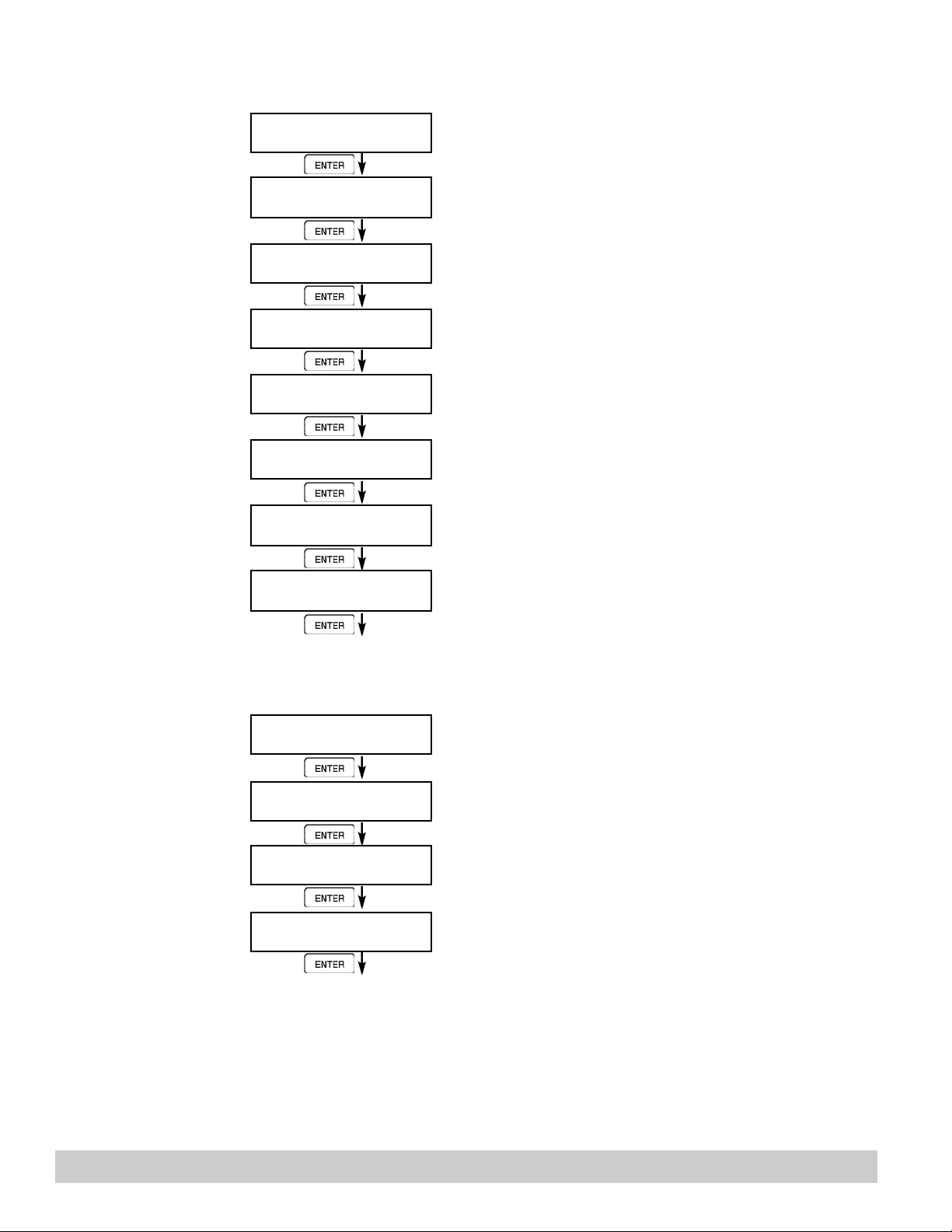
Press ENTER to begin setup of the Flow Input.
Select the desired Excitation Voltage.
Press ENTER when Analog is flashing to configure the
flow input for Analog signals .
Choose Analog Signal Type.
If Voltage selected,
Choose desired Voltage Range.
ANALOG CURRENTR A N G E
4-20mA 0-20mA
ENTER
LINEARIZATION TYPE
Linear Sqrt LinTbl
ENTER
LINEAR TABLE KA
APR01:######## gal/m
ENTER
LINEAR TABLE KA
CFr01:########
ENTER
FLOW LOW SCALE
####### gal/m
FLOW FULL SCALE
####### gal/m
ENTER
LOW FLOW CUTOFF
####### gal/m
ENTER
LOW FLOW RATE ALARM
####### gal/m
ENTER
HIGH FLOW RATE ALARM
####### gal/m
ENTER
If Current selected,
Choose desired Current Range.
Select the desired Linearization Type.
If LinTbl selected,
Enter the desired Apparent Input Flow (APR) / Correction
Factor (CFr) pair for each point in the Linearization Table.
NOTE: Enter 0 for APR value of any point (other than
APR01) to exit the routine and use the values
entered up to that point.
Enter the low flowrate corresponding to the low analog
signal. (typicaly zero)
Enter the High flowrate corresponding to the High analog
signal.
Enter the desired Low Flow Cutoff.
Enter the desired volumetric Low Rate Alarm.
This will trigger an alarm message if alarm conditions
occur. The relays are not affected.
Enter the desired volumetric High Rate Alarm.
This will trigger an alarm message if alarm conditions
occur. The relays are not affected.
Advance To
SETUP AUX INPUT
Pg 28 121-000-350 © 2001 Max Machinery, Inc.
Page 29
6.4.11
SETUPAUX
INPUT
SETUP AUX INPUT
ENTER
Press ENTER to begin setup of the Auxiliary Input.
NOTE:
When Density (Dens)
is selected, The menu
prompts will be very
similar to the
Temperature prompts.
The menus will
prompt the user for
density values and
density units.
AUX INPUT TYPE
None Dens Temp
ENTER
AUX SIGNAL TYPE
Voltage Current RTD
ENTER
INPUT SIGNAL RANGE
0-10V 0-5V 1-5V
INPUT SIGNAL RANGE
4-20mA 0-20mA
ENTER
AUX LOW SCALE
###### F
ENTER
AUX FULL SCALE
###### F
ENTER
AUX DEFAULT
###### F
ENTER
AUX LOW ALARM
###### F
ENTER
AUX HIGH ALARM
###### F
ENTER
DENS EXTRACT METHOD
Therm_Coef API_2540
ENTER
Select Temperature to set the Auxiliary Input for
Temperature inputs.
Choose Temperature Signal Type.
Advance to "Aux Default", if RTD selected.
If Voltage selected,
Choose desired Voltage Range. Skip if RTD.
If Current selected,
Choose desired Current Range. Skip if RTD.
Enter the low temperature scale corresponding to the low
temperature signal. Skip if RTD.
Enter the high temperature scale corresponding to the
high temperature signal. Skip if RTD.
Enter the Default Temperature.
The unit will use this value if the temperature input fails.
Enter the Low setpoint for the Temperature Alarm.
Enter the High setpoint for the Temperature Alarm.
Choose the Density Extraction method to be used.
(API_2540 Equation not recommended)
Advance To
SET FLUID PROPERTIES
121-000-350 © 2001 Max Machinery, Inc. Pg 29
Page 30
6.4.12
SET FLUID
PROPERTIES
SET FLUID PROPERTIES
ENTER
REF. DENSITY
###### lbs/g
ENTER
REF. TEMPERATURE
###### F
ENTER
EXPAN. FACTOR [xe-6]
########
ENTER
CALIBRATION DENSITY
########
ENTER
VISCOSITY COEF.A
0.000
ENTER
VISCOSITY COEF. B
0.000
ENTER
BASE DENSITY H2O@4C
###### lbs/g
ENTER
Press ENTER at this prompt to Set Fluid Properties.
Enter the Reference Density. This is used in the calculation of density when you have a temp transmitter and
used for corrected flow calculation if you have a density
transmitter.
Enter the Reference Temperature.
Enter the proper Expansion Factor.
(If Temp Compensated for Mass or Corrected Volume)
See Section 7.4, Calculating the Expansion Factor.
Enter the Calibration Density. This is used in calculation
of flow for analog inputs using SQRT.
Not applicable for P.0 meters
Not applicable for P.0 meters
Enter the Base Density H2O@4C. This is used in the
centistoke calculation for UVC.
6.4.13
SETUP
PULSE OUTPUT
Advance To
SETUP Pulse OUTPUT
SETUP PULSE OUTPUT
ENTER
PULSE OUTPUT USAGE
Off Vol CVol/Mass
ENTER
PULSE WIDTH
10mS 100mS
ENTER
PULSE VALUE
####### gal/P
ENTER
Advance To
SETUP ANALOG OUTPUT
Press ENTER at this prompt to setup the Pulse Output.
Select the desired Pulse Output Usage.
Select the desired Pulse Width for the Pulse Output.
Enter the desired Pulse Value for the Pulse Output (Units
per Pulse).
Pg 30 121-000-350 © 2001 Max Machinery, Inc.
Page 31
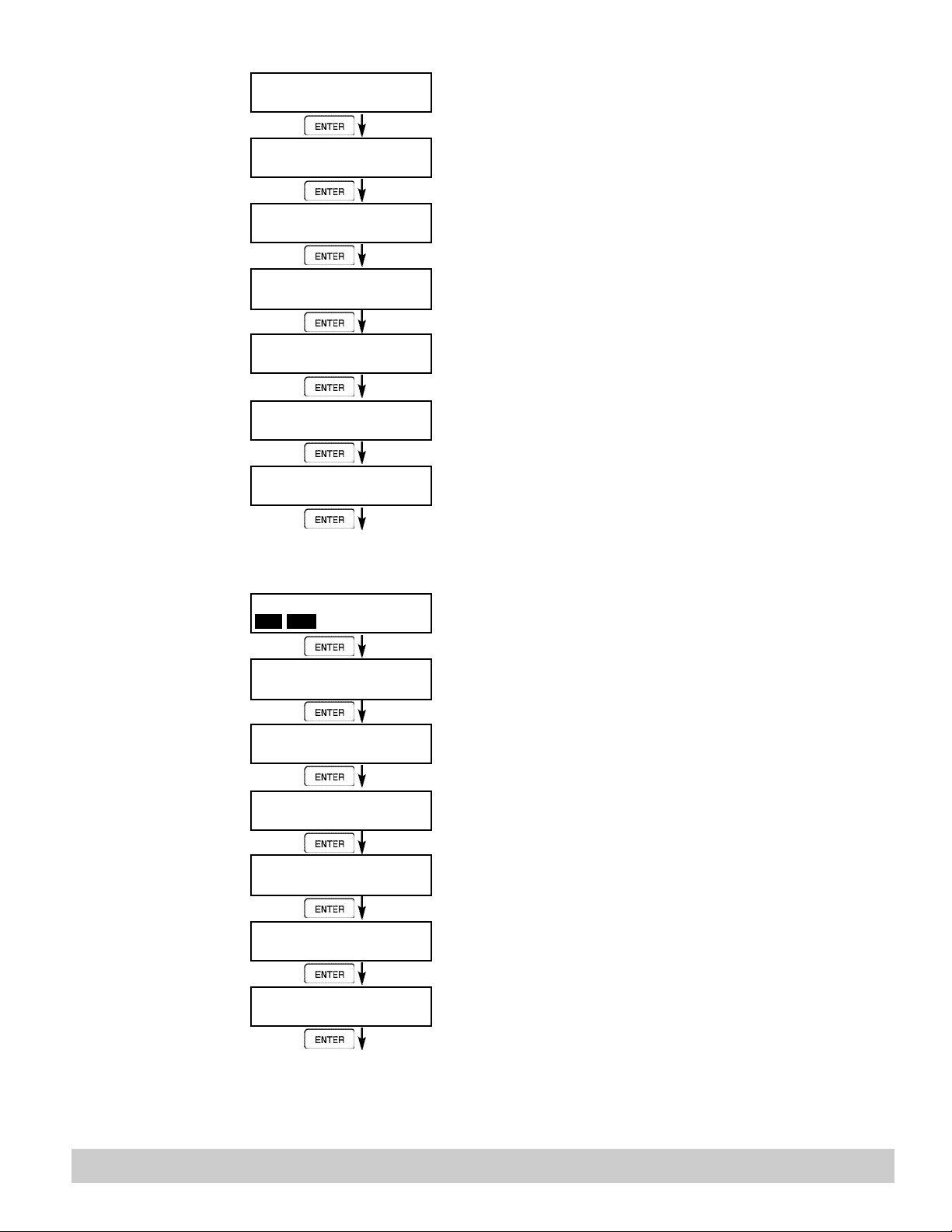
6.4.14
SETUP
ANALOG OUTPUT
SETUPANALOG OUTPUT
ENTER
ANALOG OUTPUT U S A G E
Rate Total Temp Dens
ENTER
ANALOG OUTFLOW T Y P E
Vol CVol/Mass
ENTER
ANALOG OUTPUT R A N G E
4-20mA 0-20mA
ENTER
LS ANALOG OUTPUT
####### gal/m
ENTER
FS ANALOG OUT 20mA
####### gal/m
ENTER
ANALOG OUT DAMPING
0.0
ENTER
Press ENTER when Analog is flashing to setup the
Analog Output.
Select the desired Analog Output Usage.
Only if Rate selected & Flow EQ. = Mass, Cor/Vol
Select the desired Analog Output Flow.
Select the desired current range for the Analog Output.
Enter desired Analog Output Low Scale Value.
NOTE: Units label will correspond with output usage
type selected.
Enter desired Analog Output Full Scale Value.
Enter the desired Analog Output Damping Constant.
6.4.15
SETUP RELAYS
(Relay 1 & Relay 2)
NOTE:
In Batch mode, Relay 1
is reserved for Preset,
Relay 2 is reserved for
Prewarn.
Advance To
SETUP RELAYS
SETUP RELAYS
Rly1 Rly2 Rly3 Rly4
ENTER
RELAY 1 USAGE
RATE TOTAL NA
ENTER
RELAY 1 DELAY sec
0
ENTER
RELAY 1 MODE
LO_ALARM HI_ALARM
ENTER
RELAY 1 DURATION
#####
ENTER
RELAY 1 SETPOINT
####### gal
ENTER
RELAY 1 HYSTERESIS
##### gal/m
ENTER
Select the desired Relay for setup.
(Relays 3 & 4 Optional)
If Relay 1 or Relay 2 Selected,
Select Rate, Total or NA.
If Rate selected, enter desired relay activation delay
value.
Select the desired Relay Activation.
Low: Relay activates when reading is below setpoint.
High: Relay activates when reading is above setpoint.
If Total Selected, Enter desired Relay Duration.
Enter the desired Setpoint. The Setpoint can be edited in
run mode using the PRE 1 key (PRE 2 key for Relay 2).
If Rate, selected, Enter desired Relay Hysteresis.
121-000-350 © 2001 Max Machinery, Inc. Pg 31
Page 32

RELAY NOTES & CONSIDERATIONS
1. Relay activation is based on the computed readings not the displayed value. Therefore the display
damping factor will not affect the relay response time. The RELAY DELAY feature allows the
user to enter a time delay for relay activation. This feature is very useful in applications where
short over/under range conditions are not considered alarm conditions.
2. When INSTRUMENT TYPE is set to batcher, Relay 1 is reserved for PRESET and Relay 2 is
reserved for PREWARN. (the Prewarn value is relative to the Preset value. Input the
number of units that Relay 2 should “drop out” in advance of Relay 1.)
3. Setting the relays to NA (Not Assigned), will allow the relay activation to be controlled via the
RS-232 Serial ports.
Pg 32 121-000-350 © 2001 Max Machinery, Inc.
Page 33
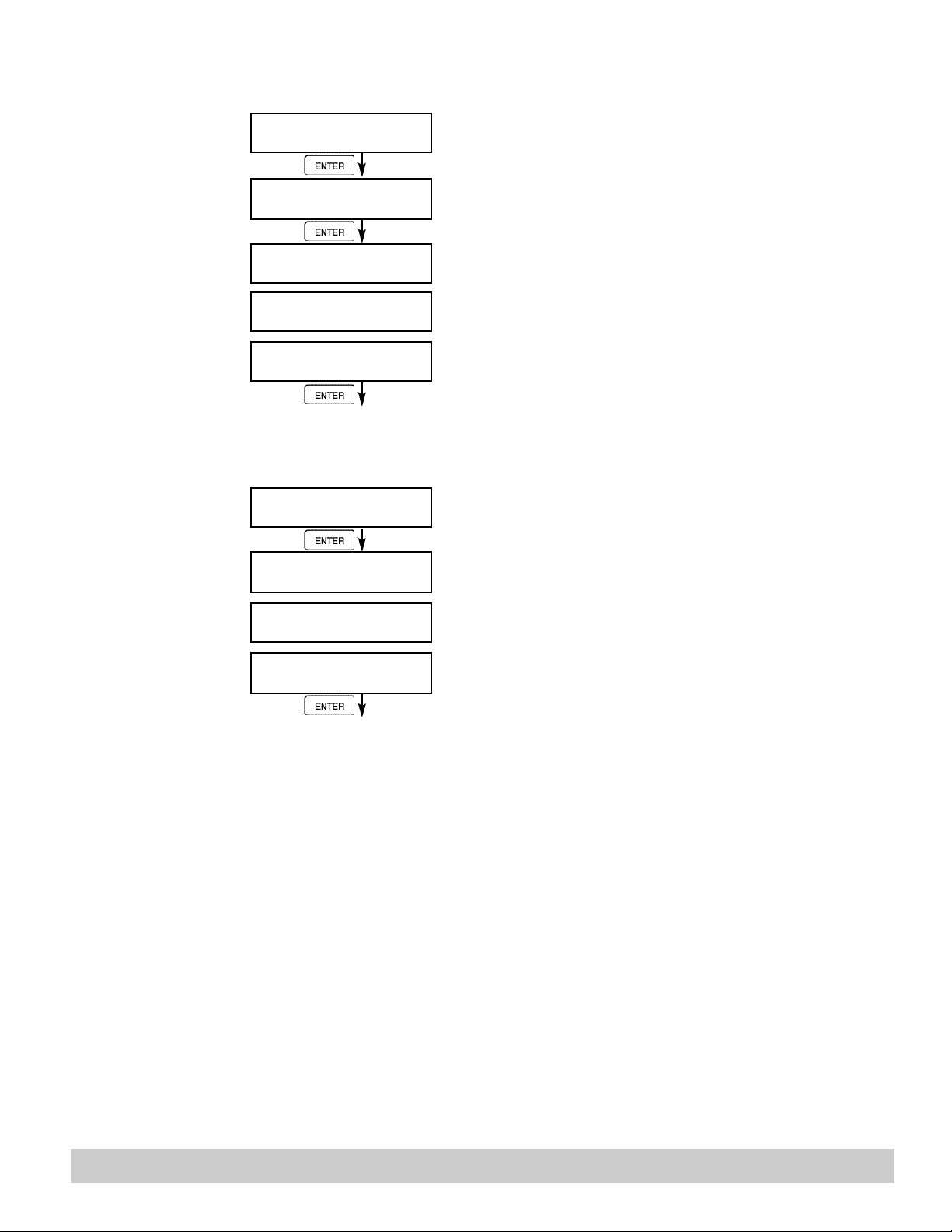
6.4.16
SETUP CONTROL
INPUTS
(RATE/TOTAL)
SETUP CONTROL INPUTS
ENTER
SETUP CONTROL INPUTS
Input1 Input2 Input3
ENTER
C O N T R O L INPUT1 USAGE
INHIBIT_TOTAL NA
Press Enter to begin setup of the Control Inputs.
Select the desired Control Input for setup.
If Control Input 1 Selected,
Select Inhibit Total or NA (Not Assigned).
6.4.17
SETUP CONTROL
INPUTS
(BATCH)
C O N T R O L INPUT2 USAGE
RESET_TOTAL NA
CONTROL INPUT3 USAGE
Prn Ack KeyLk NA
ENTER
Advance To
SETUP REALTIME CLOCK
SETUP CONTROL INPUTS
Input1 Input2 Input3
ENTER
CONTROL INPUT1 USAGE
Start Rst/Start NA
CONTROL INPUT2 USAGE
Stop Stop/Rst NA
CONTROL INPUT3 USAGE
Rst Prn KeyLk Ack NA
ENTER
Advance To
SETUP REALTIME CLOCK
If Control Input 2 Selected,
Select Reset Total or NA (Not Assigned).
If Control Input 3 Selected,
Select Prn (Print), Ack (acknowledge), KeyLk (Keylock)
or NA (Not Assigned). ACK will acknowledge and clear
alarms and warning messages.
Note: Alarms may reassert themselves if alarm conditions are still present.
Select the desired Control Input for setup.
If Control Input 1 Selected,
Select Start ,Reset/Start, NA (Not Assigned).
If Control Input 2 Selected,
Select Stop, Stop/Reset, NA (Not Assigned).
If Control Input 3 Selected,
Select Prn (Print), Ack (acknowledge), KeyLk (Keylock)
or NA (Not Assigned). ACK will acknowledge and clear
alarms and warning messages.
Note: Alarms may reassert themselves if alarm conditions are still present.
121-000-350 © 2001 Max Machinery, Inc. Pg 33
Page 34
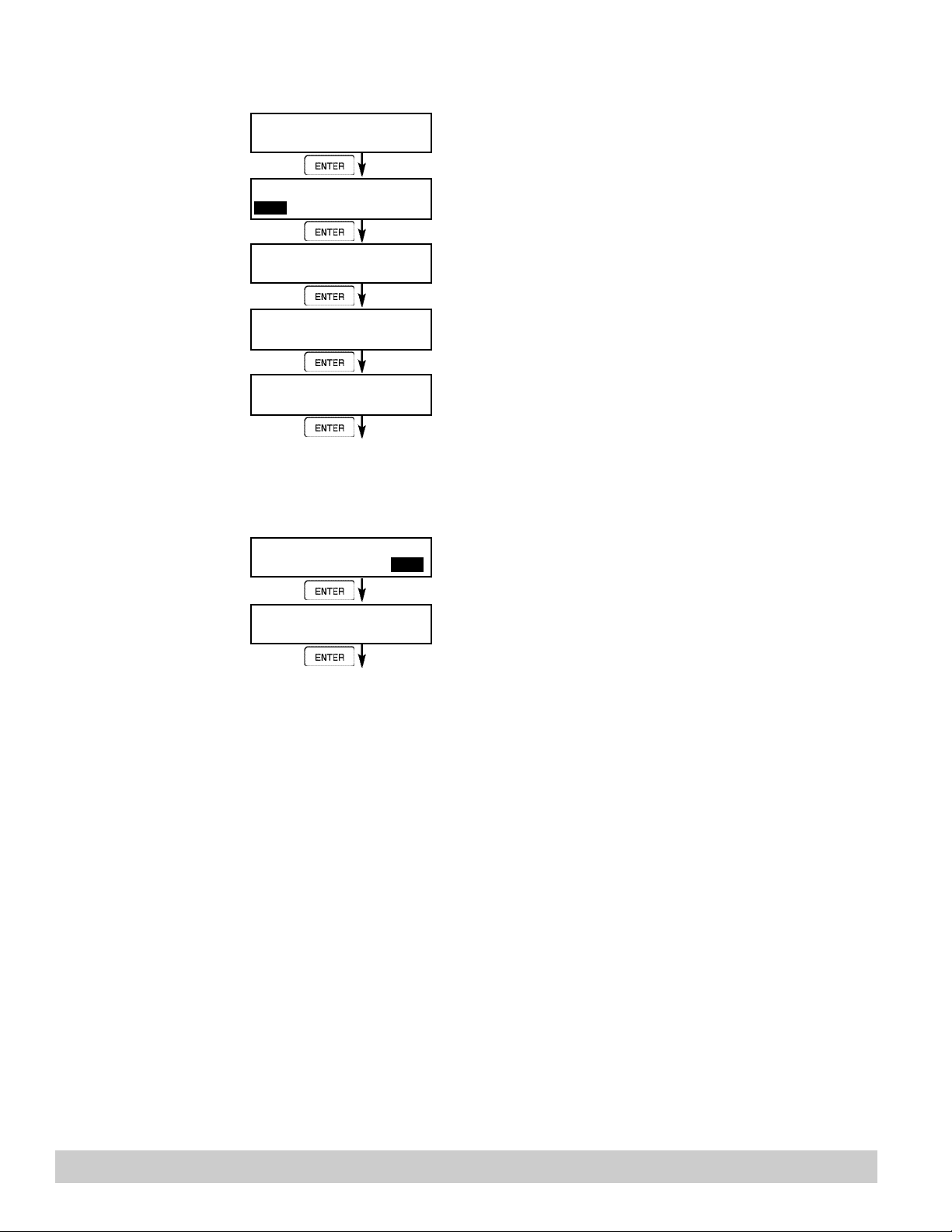
6.4.18
SETUP REALTIME CLOCK
(Time)
6.4.19
SETUP REALTIME CLOCK
(Date)
SETUP REALTIME CLOCK
ENTER
SETUP REALTIME CLOCK
Time Date
ENTER
CLOCK TYPE
24HR 12HR
ENTER
SELECT CLOCK AM/PM
AM PM
ENTER
Press Enter to begin setup of the Realtime Clock.
Select Time to set the time.
Select 24Hr or 12Hr clock
If 12Hr Clock,
Enter AM or PM
TIME OF DAY HH:MM:SS
##:##:##
ENTER
Advance To
SETUP REALTIME CLOCK
(Date)
SETUP REALTIME CLOCK
Time Date
ENTER
DATE: MONTH,DAY,YEAR
##/##/####
ENTER
Advance To
SERIAL USAGE
Enter time of day.
Select Date to enter the date.
Enter the date. (Month, Day, Last two digits of Year)
Pg 34 121-000-350 © 2001 Max Machinery, Inc.
Page 35
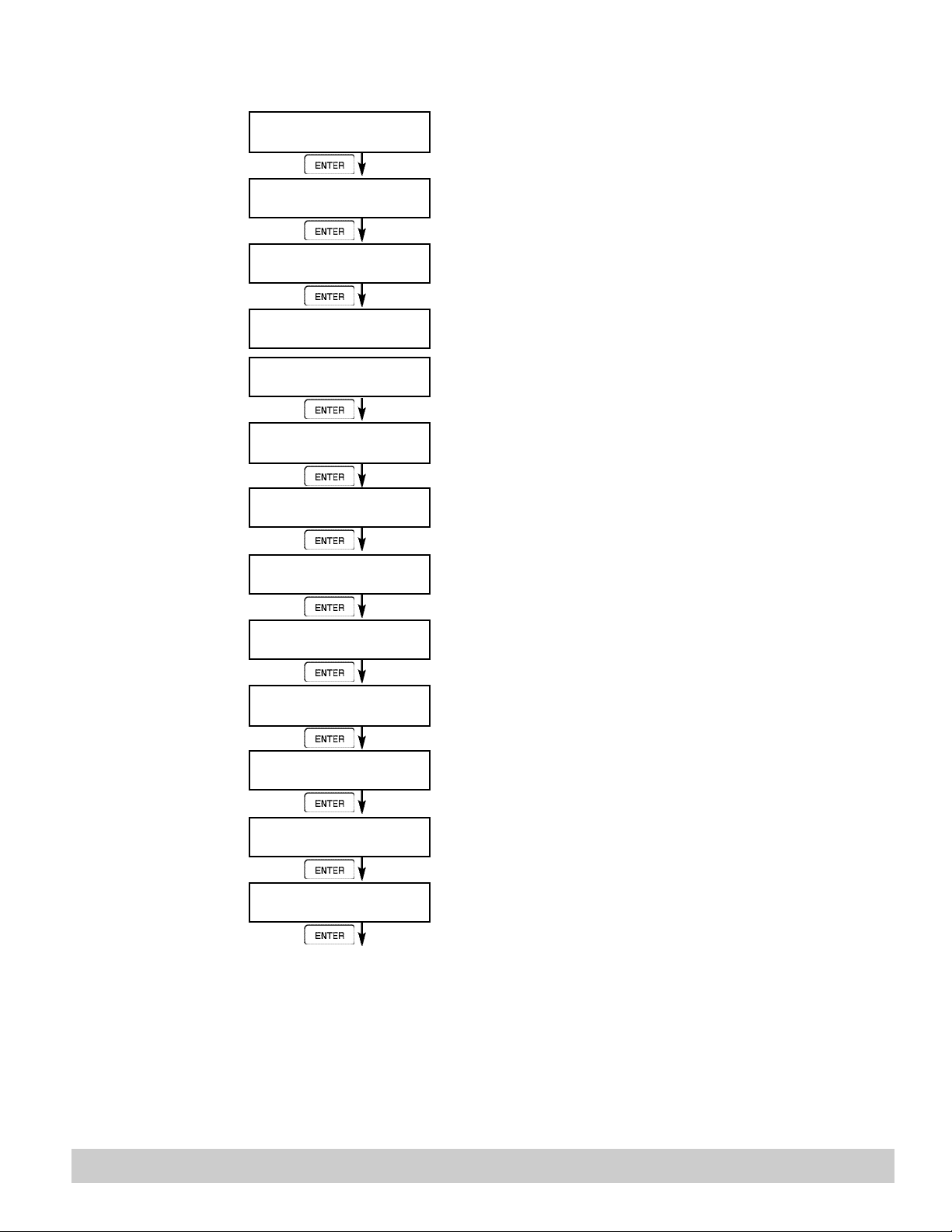
6.4.20
SERIAL USAGE
SERIAL USAGE
ENTER
SERIAL HARDWARE
RS232 RS485
ENTER
DEVICE ID
##
ENTER
BAUD RATE
300 600 1200 <more>
BAUD RATE
2400 4800 9600 19200
ENTER
PARITY
None Odd Even
ENTER
HANDSHAKING
None Softwre Hardwre
ENTER
DEVICE LINE FEED
<CR> <CR+LF>
ENTER
MODEM OPTIONS
No Yes
ENTER
MODEM INIT MASTER
No Yes
ENTER
MODEM AUTOANSWER
No Yes
ENTER
CALL OUT PHONE #
0
ENTER
CALL OUT TIME
##:##:##
ENTER
Press Enter to begin setup of the Serial Port.
Select Serial Hardware type for standard port.
Select the Device ID.
Select the desired Baud Rate.
(If <more> selected)
Select the desired Parity.
Set the Handshake.
Choose end of line termination. Only choose <CR> if
your external device automatically assigns a line feed for
every <CR> carriage return.
Select "Yes" if the serial port will be used to control a
modem.
Select "Yes" to have the unit engage in a configuration
conversation with the modem on power up .
Select the desired Modem Auto Answer mode.
Enter the Call Out Phone Number to be dialed for "Call
Out Time" or "Print On Error/Alarm".
Enter the time of day to perform Call Out transmission.
Continued on Next Page
121-000-350 © 2001 Max Machinery, Inc. Pg 35
Page 36
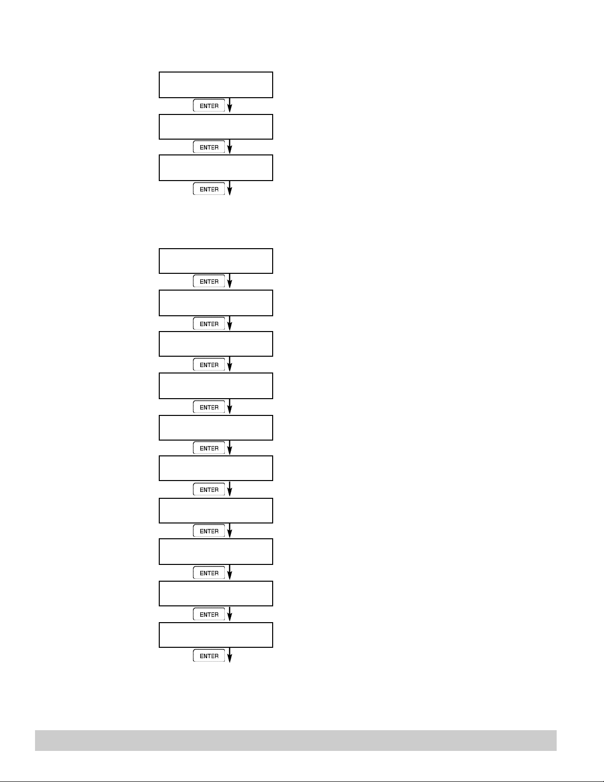
ENTER
ENTER
ENTER
ENTER
ENTER
ENTER
ENTER
ENTER
ENTER
ENTER
ENTER
ENTER
ENTER
6.4.20
SERIAL USAGE
(continued)
CALL ON ERROR/ALARM
No Yes
Select "Yes" to have the unit perform a Call Out transmission upon error/alarm condition.
6.4.21
SETUP
DATALOG/PRINT
(Configure)
NUMBER OF REDIALS
0
HANGUP IF 2MIN INACT
No Yes
Advance To
SETUP DATALOG/PRINT
SETUP DATALOG/PRINT
SETUP DATALOG/PRINT
Config Select_list
OUTPUT FORMAT
Printer Term Dbase
PAGE LENGTH [66 max]
66
Enter the number of redials to be performed on call out
time if busy or no answer. (error/alarm tries until connected)
Select "Yes" to perform hangup if there is inactivity for
more than 2 minutes.
Press Enter to setup the Datalog/Print information.
Select Config to configure the Datalog/Print information.
Select the type of Output Format.
Enter the desired Page Length.
If Printer selected above.
TOP MARGIN [60 max]
3
DATALOG PRINT ONLY
No Yes
PRINT TIME HH:MM:SS
00:00:00
Print interval
00:00:00
ENABLE PRINT KEY
NO YES
PRINT END OF BATCH
NO YES
Advance To
SETUP DATALOG/PRINT
(Select_list)
Enter the desired Top Margin.
If Printer selected above.
Select Yes to record events to the datalogger only.
Events will not be sent to the serial port.
Enter Print Time, printer will print at this time every day.
Enter 00:00:00 to inhibit print time.
Enter Print Interval,
Enter 00:00:00 to inhibit print interval..
Select YES to enable Print Key.
Select NO to disable Print Key
Batch mode only.
Select Yes to print at end of batch.
Pg 36 121-000-350 © 2001 Max Machinery, Inc.
Page 37
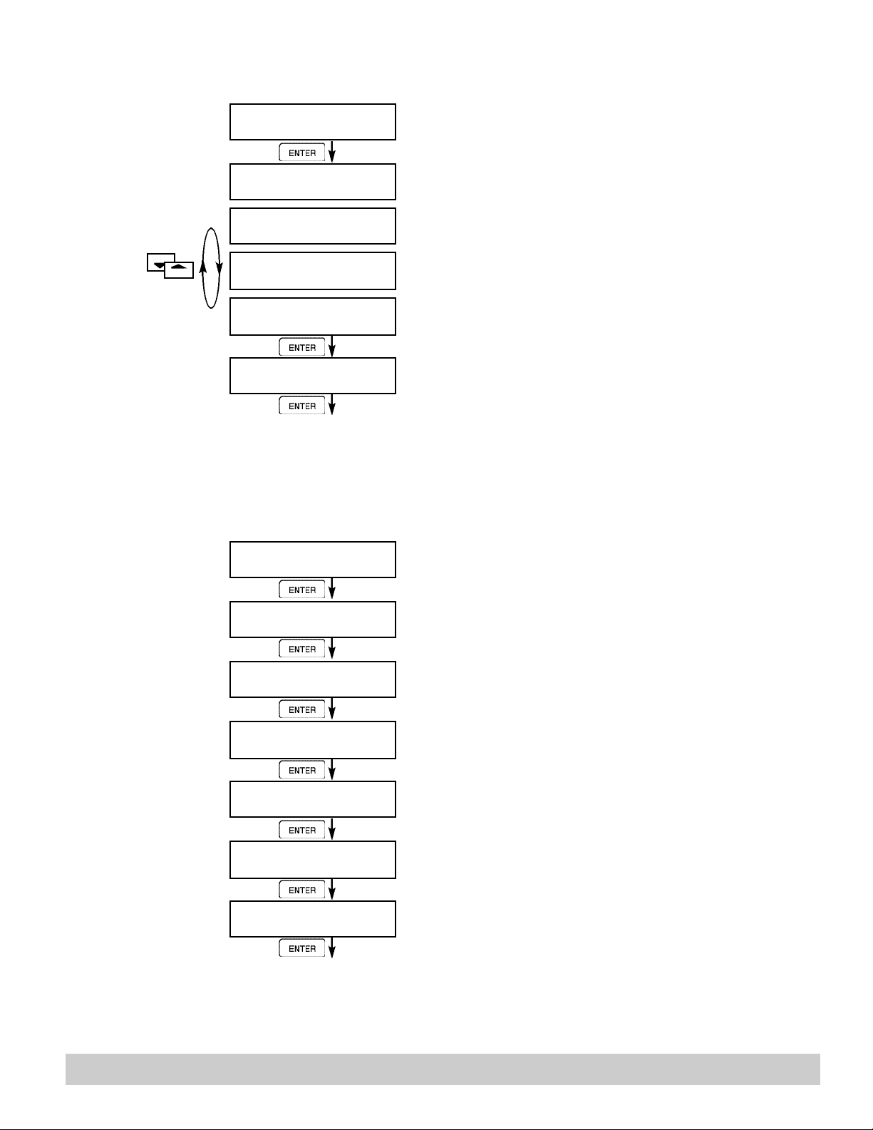
START
6.4.22
SETUP
DATALOG/PRINT
(Select_list)
SET DATALOG/PRINT
ENTER
SET DATALOG/PRINT
Config Select_list
Press enter to begin Setup Datalog/Print routine.
Press enter when Select_list is selected to setup print list.
STOP
List Items:
Total
Rate
Pre1
temp
grand
pre2
dens
time
6.4.23
ADMINISTRATIVE
SETUP
PRINT LIST ITEMS
TOTAL YES
PRINT LIST ITEMS
RATE YES
PRINT LIST ITEMS
PRE 1 YES
ENTER
PRINT LIST ITEMS
DataLog size =001489
ENTER
Advance To
ADMINISTRATIVE SETUP
ADMINISTRATIVE SETUP
ENTER
OPERATOR PASSWORD
*****
ENTER
S U P E RVISOR PA S S W O R D
*****
ENTER
SOFTWARE VERSION
vxx.xx
ENTER
PRODUCT ORDER CODE
121 SERIESxxxxxxx
ENTER
UNIT SERIAL NUMBER
00000
ENTER
SENSOR SERIAL N U M B E R
00000
ENTER
Use Up and Down arrow keys to view list status.
Press the Corresponding function key to the items that
you wish to add or remove from the list.
Items marked with Yes will be added to the list,
items marked with No will be removed from the list.
The Select Print List Information display shows the current possible Datalog size.
Press Enter to begin Administrative Setup.
Enter Operator Password. (Factory Set to 0)
Enter Supervisor Password.
(Factory Set to 2000)
This display is used to show the software version of the
installed software.
This display is used to show the product order code
(model number).
This display is used to show the unit's serial number.
This display is used to show the sensor's serial number.
Advance To
SETUP NETWORK CARD
121-000-350 © 2001 Max Machinery, Inc. Pg 37
Page 38
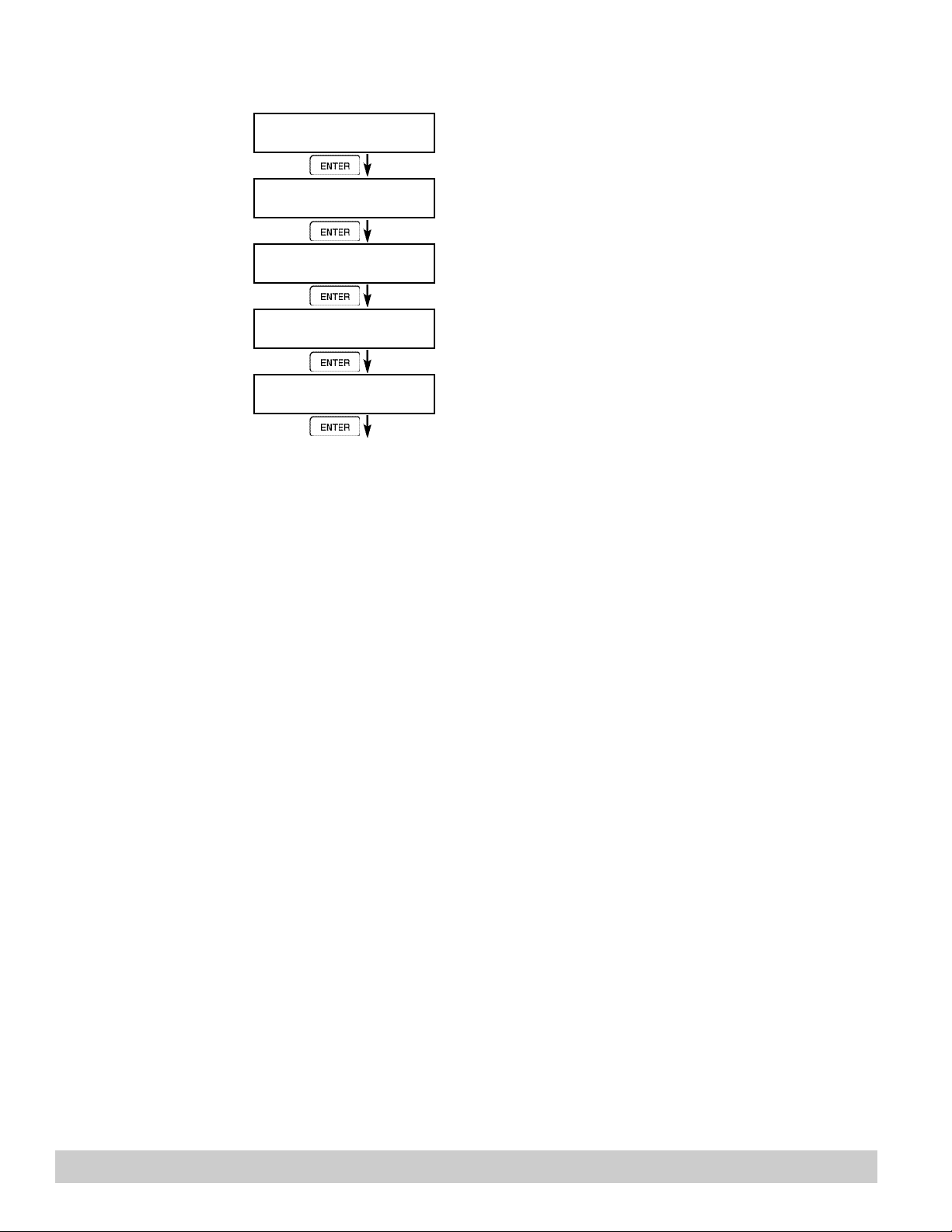
6.4.24
SETUP
NETWORK CARD
(optional)
SETUP NETWORK CARD
ENTER
SELECT NTW PROTOCOL
ModbusRTU
ENTER
NETWORK DEVICE ID
1
ENTER
BAUD RATE
2400 4800 9600 19200
ENTER
PARITY
None Odd Even
ENTER
Advance To
SELECT EZ SETUP?
Press Enter to setup Network Card
Select desired Network Protocol.
Enter the device address on network (00-255).
Select the desired Baud Rate.
Select the desired Parity.
Pg 38 121-000-350 © 2001 Max Machinery, Inc.
Page 39

Principle Of Operation
7.1 General:
General Operation
The 121 Series Flow Computer uses several internal calculations to compute the compensated flow based on
specific data input. Several computations are performed to arrive at the uncompensated flow, temperature,
density and viscosity. This information is then used to compute the Corrected Volume Flow or Mass Flow.
7.3 Flow Equations:
Input Flow Computation:
Linear or External SQRT
Input Flow = [% input span • (flow FS - flow low scale)]+ flow low scale
Input Flow Computation:
General Case
Tf = [% input span • (temp FS - Temp low scale)] + temp low scale
RTD Case
Tf = f(measured input resistance)
Input Density Computation:
Temperature Transmitter
density = reference density • (1 - Therm.Exp.Coef. • (Tf-Tref))
Density Transmitter
density = [% input span • (density FS - density low scale)] + density low scale
Uncompensated Flow Computation:
Pulse Input; Average K-Factor
Volume Flow = input frequency • time scale factor
Pulse Input; Linear Table
Volume Flow = input frequency • time scale factor
Analog Input; Linear
2
K-Factor
K-Factor (Hz)
Volume Flow = input flow
Analog Input; Linear Table
Volume Flow = input flow • correction factor (input flow)
121-000-350 © 2001 Max Machinery, Inc. Pg 39
Page 40

Corrected Volume Flow Computation:
Temperature Transmitter
Standard Volume Flow = volume flow • (1 - Therm.Exp.Coef. • (Tf-Tref))
Density Transmitter
Standard Volume Flow = volume flow • density
Mass Flow Computation:
Mass Flow = volume flow • density
2
reference density
Pg 40 121-000-350 © 2001 Max Machinery, Inc.
Page 41

7.4 Calculating the Expansion Factor
Calculating
Expansion Factor
Two temperature-specific gravity pairs will be required to compute the temperature coefficient.
The reference temperature is simply chosen by the user. Common reference temperatures are 60 F or 15 C.
The reference temperature should be chosen so that it is in the application temperature range. (ex. application
temperature range -10 to 120 F, reference temperature of 60 F chosen.)
Enter the reference temperature you have chosen at this point.
The reference specific gravity corresponds to the fluid SPECIFIC GRAVITY at the reference temperature
chosen.
You may convert the fluid density information to specific gravity if it is in units other than specific gravity. Use
EQ1.
CAUTION: Since the expansion factor is based on a per degree change in temperature, the temperatures used in
the following equations must match (Fahrenheit or Centigrade) the units used on the indicator display programming.
Expansion Factor
Equations
EQ1.
Spec.Grav. = Density of Fluid / Density of Water
Given the reference temperature, reference specific gravity, a second temp. and a second
Spec.Grav., the Expansion Factor (C Factor) can be computed as follows:
EQ2. Used for Liquid Mass and Corrected Volume Equations
C = 1 - √ (Spec.Grav.2 / Ref.Spec.Grav.) x 1,000,000
Temp.2 - Ref.Temp
Given the reference temperature, reference density, a second temp. and a second density,
the Expansion Factor (C Factor) can be computed as follows:
Example: Diesel fuel (0.845@20˚C, 0.830@42˚)
C = 1 - √ 0.83/0.845 x 1,000,000 = 405.25
(42-20)
EQ3. Used for Liquid Mass and Corrected Volume Equations
C = 1 - √ (Dens.2 / Ref.Dens.) x 1,000,000
Temp.2 - Ref.Temp
121-000-350 © 2001 Max Machinery, Inc. Pg 41
Page 42

7.6 Linearization Table
7.6.1 Linearization Table General Information
The Linearization Table is used when the flow input device gives a nonlinear input signal. The
unit uses up to 16 different points, as entered by the operator, to form a curve for linearizing
the input signal.
Notes:
1) A minimum of three points must be set up.
2) If "0" is entered for the frequency of any point other than point 1, the Flow Computer
assumes there are no more points above the points that preceded them. The display will
advance to the next setup prompt. Extrapolation is taken from the last two nonzero points.
3) If the input frequency is above the highest or below the lowest frequency programmed, the
unit will use the last known point for the K factor in computing the resulting actual flow.
4) Frequencies or apparent flows should be entered in ascending order.
7.6.2 Linearization Table for Pulse Inputs
The linearization table for pulse inputs programming is quite simple when values of frequency and flow are
known. The Flow Computer asks for 16 different frequencies (Freq) and 16 corresponding K factors (K). It then
uses this data to determine what the actual flow is for any given input frequency. Usually the necessary data is
provided with the flowmeter.
7.6.3 Linearization Table for Analog Inputs
The Linearization Table for Analog inputs programming is similar to the Pulse input setup. The Flow Computer
asks for 16 different flow rates (apparent flow) and 16 corresponding Correction Factors. It then uses this data
to determine what the Actual flow is for any given apparent input signal. Again, a minimum of three points must
be set up.
Correction factor = Actual Flow
Apparent Input Flow
The same rules that applied for the Digital setup apply for the Analog setup as well.
The Flow Computer prompts you for the Apparent input signal (APR) and a correction factor (CFr) to multiply
it by to yield true actual flow.
Pg 42 121-000-350 © 2001 Max Machinery, Inc.
Page 43
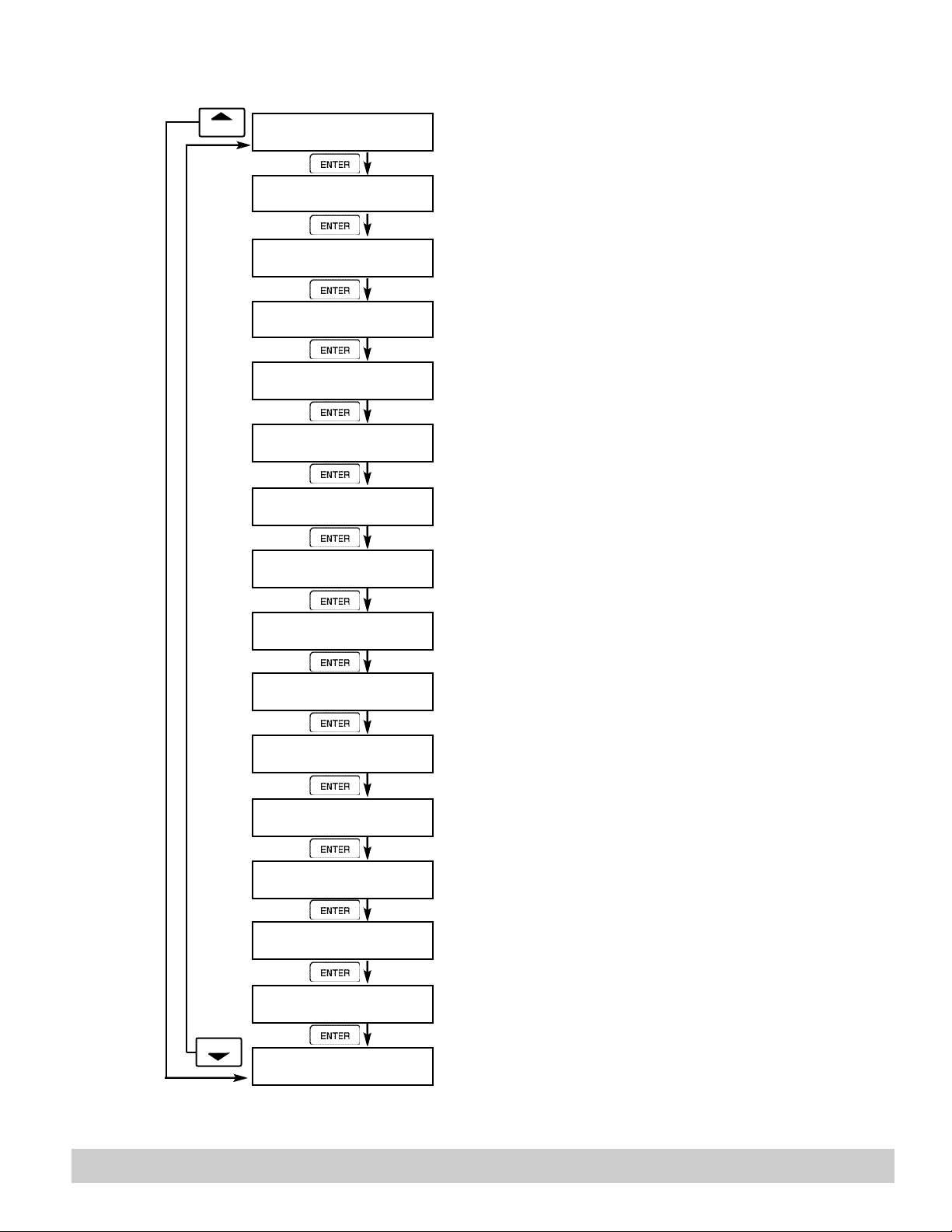
8.1.1
TOP LEVEL
TEST MENUS
START
SELECT OPERATE STATE
Run Setup Test
ENTER
Audit Trail
ENTER
Error history
ENTER
Print System Setup
ENTER
Keypad Test
ENTER
Display test
ENTER
Calibrate
ENTER
Analog In Test
Select Test to enter the instrument test & calibration routine.
NOTE: Supervisor (Service) password required
to gain access to this mode.
Refer to Page 44 for Details.
Refer to Page 44 for Details.
Refer to Page 44 for Details.
Refer to Page 45 Details.
Refer to Page 45 for Details.
Refer to Pages 46 -50 for Details.
Refer to Page 50 Details.
STOP
ENTER
Pulse input test
ENTER
Analog out test
ENTER
Excitation out test
ENTER
Pulse out test
ENTER
Relay Test
ENTER
Control inputs test
ENTER
Battery Voltage Test
ENTER
Data logger utility
Refer to Page 51 for Details.
Refer to Page 51 for Details.
Refer to Page 51 for Details.
Refer to Page 52 for Details.
Refer to Page 52 for Details.
Refer to Page 52 for Details.
Refer to Page 53 for Details.
Refer to Page 53 for Details.
121-000-350 © 2001 Max Machinery, Inc. Pg 43
Page 44
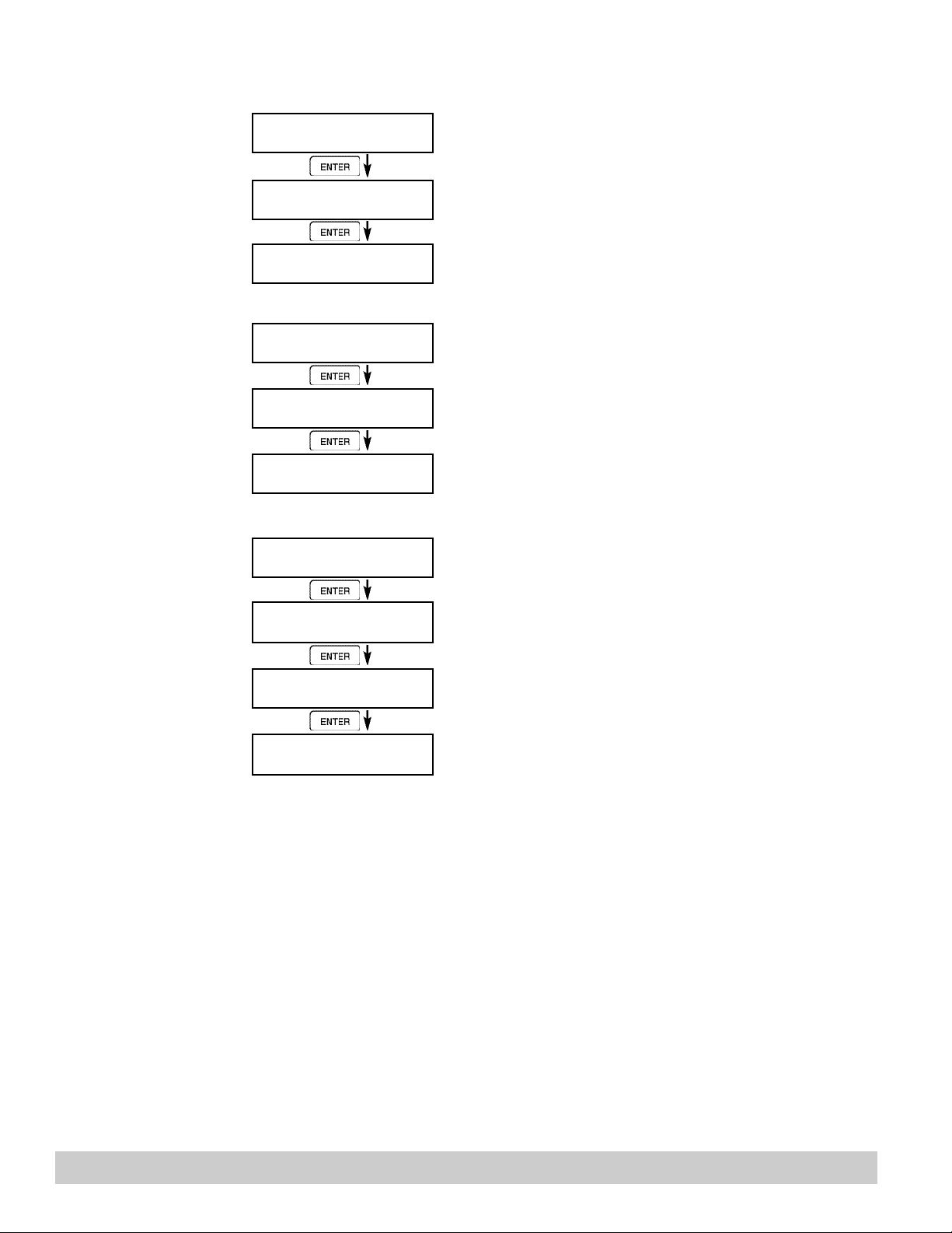
ENTER
8.2.1
Audit Trail
Submenu Group
8.2.2
Error History
Submenu Group
8.2.3
Print System Setup
Submenu Group
Audit Trail
ENTER
Audit Trail nnnnn
hh:mm:ss mm/dd/yy
ENTER
Audit Trail
Error history
ENTER
Error history
Flow rate alarm low
ENTER
Press Enter to view the audit trail information.
The audit trail is viewed in this format:
nnnnn= number of critical menu changes,
hh:mm:ss; mm/dd/yy = time and date of last change.
Press Menu to get back to audit trail top-level menu.
Press Enter to view error history.
NOTE: Press Print Key to print Error History. Printout will
include time/date of each errors first occurrence.
Press Up/Down arrow keys to scroll through error message
history. Press CLEAR to clear entire error log.
Error history
Print System Setup
ENTER
Print System Setup
Press ENTER to print
ENTER
Print System Setup
—— Printing ——-
Print System Setup
Press Menu to get back to error history top=level menu.
Press enter key to enter print system setup submenu
Press enter to begin printing the system setup.
This message will display as the data transmission takes
place.
Press Menu to get back to print system setup top-level menu.
Pg 44 121-000-350 © 2001 Max Machinery, Inc.
Page 45
8.2.4
Keypad test
Submenu Group
Keypad test
ENTER
Keypad test
Key pressed—> ENTER
ENTER
Keypad test
Press Enter to enter keypad test
Press the various keys and the display will show the key that
was pressed. Press Menu to exit the test
Press Menu to get back to Keypad test top-level menu.
8.2.5
Display test
Submenu Group
Display test
ENTER
00000000000000000000
00000000000000000000
ENTER
Display test
Press Enter to enter display test.
Upon pressing enter each digit on the display will scroll 0-9
then A-Z. Press menu to exit the test.
Press Menu to get back to Display test top-level menu.
121-000-350 © 2001 Max Machinery, Inc. Pg 45
Page 46
STOP
STOP
ALL I/O REFERNCES ARE CALIBRATED AT THE FACTORY PRIOR TO SHIPMENT CAUTION:
This unit must be calibrated using precision and calibrated equipment.
Equipment needed is as follows: Frequency Generator, Digital Multimeter,
Precision Current/Voltage Source, Oscilloscope, Frequency Counter.
Calibration
Submenu Group
8.2.6
Calibrate CH1 0mA
Submenu Group
8.2.7
Calibrate CH1 20mA
Submenu Group
Calibrate
ENTER
Calibrate ch1 0mA
Iin=TB1-3 GND=TB1-4
ENTER
Calibrate ch1 0mA
CALIBRATING ——
Calibrate ch1 0mA
*** DONE ***
Calibrate ch1 0mA
Iin=TB1-3 GND=TB1-4
Calibrate ch1 20mA
Iin=TB1-3 GND=TB1-4
ENTER
Calibrate ch1 20mA
0 CALIBRATING ——
Press Enter to begin the calibration routine. (Please note the
caution above)
Connect Current Source (+) TB1-3, (-) TB1-4. Input 0mA and
press Enter.
This message is displayed during calibration.
This message is displayed when the 0mA calibration is finished.
The display will automatically return to the Calibrate CH1
0mA submenu. Press the Down arrow key to advance to the
CH1 20mA calibration.
Connect Current Source (+) TB1-3, (-) TB1-4. Input 20mA
and press Enter.
This message is displayed during calibration.
Calibrate ch1 20mA
*** DONE ***
Calibrate ch1 20mA
Iin=TB1-3 GND=TB1-4
This message is displayed when the 20mA calibration is finished.
The display will automatically return to the Calibrate CH1
20mA submenu. Press the Down arrow key to advance to
the CH2 0mA calibration.
Advance to
Calibrate ch2 0mA
Pg 46 121-000-350 © 2001 Max Machinery, Inc.
Page 47
8.2.8
Calibrate CH2 0mA
Submenu Group
Calibrate ch2 0mA
Iin=TB1-8 GND=TB1-4
ENTER
Calibrate ch2 0mA
0 CALIBRATING ——
To Calibrate: Connect Current Source (+) TB1-8, (-) TB1-4.
Input 0mA and press Enter.
This message is displayed during calibration.
8.2.9
Calibrate CH2 20mA
Submenu Group
Calibrate ch2 0mA
*** DONE ***
Calibrate ch2 0mA
Iin=TB1-8 GND=TB1-4
STOP
Calibrate ch2 20mA
Iin=TB1-8 GND=TB1-4
ENTER
Calibrate ch2 20mA
0 CALIBRATING ——
Calibrate ch2 20mA
*** DONE ***
Calibrate ch2 20mA
Iin=TB1-8 GND=TB1-4
STOP
Advance to
Calibrate ch1 0V
This message is displayed when the 0mA calibration is finished.
The display will automatically return to the Calibrate CH2
0mA submenu. Press the Down arrow key to advance to the
CH2 20mA calibration.
To Calibrate: Connect Current Source (+) TB1-8, (-) TB1-4.
Input 20mA and press Enter.
This message is displayed during calibration.
This message is displayed when the 20mA calibration is finished.
The display will automatically return to the Calibrate CH2
20mA submenu. Press the Down arrow key to advance to
the CH1 0V calibration.
121-000-350 © 2001 Max Machinery, Inc. Pg 47
Page 48
STOP
STOP
8.2.10
Calibrate CH1 0V
Submenu Group
Calibrate ch1 0V
Vin=TB1-2 GND=TB1-4
ENTER
To Calibrate: Connect Voltage Source (+) TB1-2, (-) TB1-4.
Input 0V and press Enter.
8.2.11
Calibrate CH1 10V
Submenu Group
Calibrate ch1 0V
0 CALIBRATING ——
Calibrate ch1 0V
*** DONE ***
Calibrate ch1 0V
Iin=TB1-2 GND=TB1-4
Calibrate ch1 10V
Iin=TB1-2 GND=TB1-4
ENTER
Calibrate ch1 10V
0 CALIBRATING ——
Calibrate ch1 10V
*** DONE ***
Calibrate ch1 10V
Iin=TB1-2 GND=TB1-4
This message is displayed during calibration.
This message is displayed when the 0V calibration is finished.
The display will automatically return to the Calibrate CH1 0V
submenu. Press the Down arrow key to advance to the CH1
10V calibration.
To Calibrate: Connect Voltage Source (+) TB1-2, (-) TB1-4.
Input 10V and press Enter.
This message is displayed during calibration.
This message is displayed when the 10V calibration is finished.
The display will automatically return to the Calibrate CH1 10V
submenu. Press the Down arrow key to advance to the CH2
0V calibration.
Advance to
Calibrate ch2 0V
Pg 48 121-000-350 © 2001 Max Machinery, Inc.
Page 49
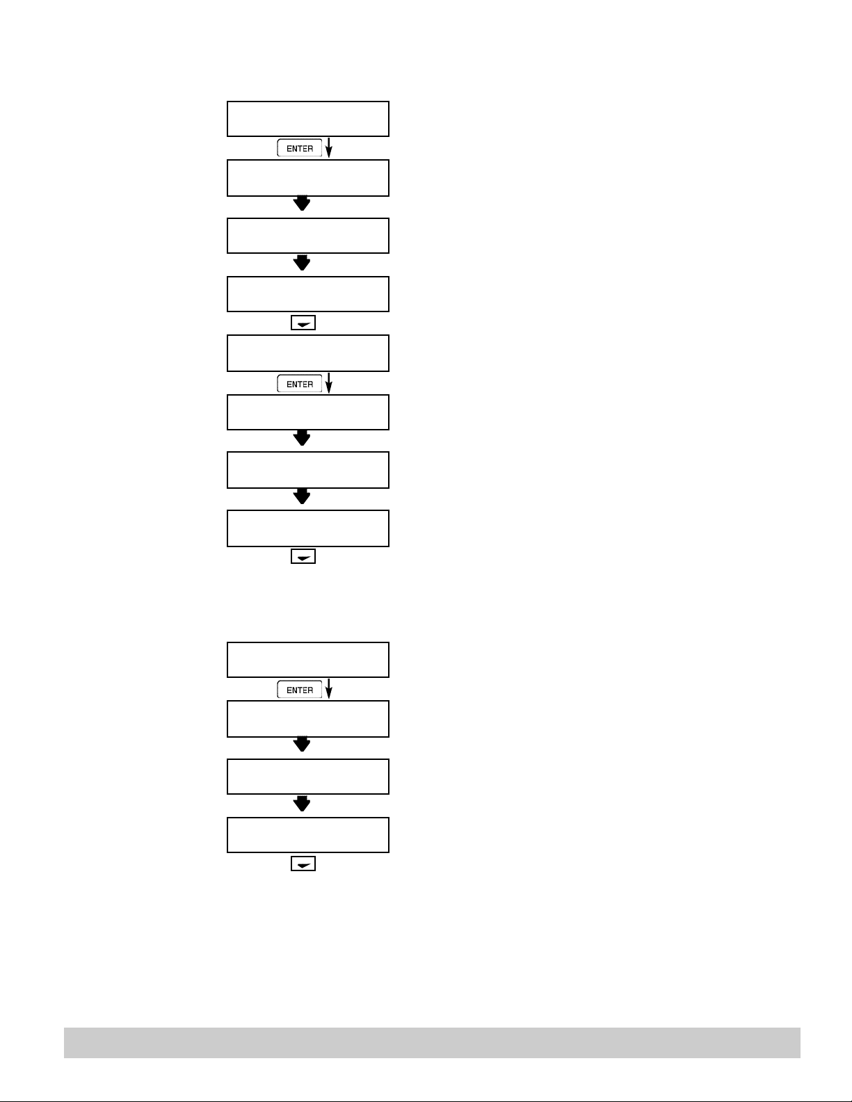
8.2.12
Calibrate CH2 0V
Submenu Group
Calibrate ch2 0V
Vin=TB1-5 GND=TB1-4
ENTER
Calibrate ch2 0V
0 CALIBRATING ——
To Calibrate: Connect Voltage Source (+) TB1-5, (-) TB1-4.
Input 0V and press Enter.
This message is displayed during calibration.
8.2.13
Calibrate CH2 10V
Submenu Group
Calibrate ch2 0V
*** DONE ***
Calibrate ch2 0V
Iin=TB1-5 GND=TB1-4
STOP
Calibrate ch2 10V
Iin=TB1-5 GND=TB1-4
ENTER
Calibrate ch2 10V
0 CALIBRATING ——
Calibrate ch2 10V
*** DONE ***
Calibrate ch2 10V
Iin=TB1-5 GND=TB1-4
STOP
Advance to
Calibrate 100ohm RTD
This message is displayed when the 0V calibration is finished.
The display will automatically return to the Calibrate CH2 0V
top-level menu. Press the Down arrow key to advance to the
CH2 10V calibration.
To Calibrate: Connect Voltage Source (+) TB1-5, (-) TB1-4.
Input 10V and press Enter.
This message is displayed during calibration.
This message is displayed when the 10V calibration is finished.
The display will automatically return to the Calibrate CH2 10V
top-level menu. Press the Down arrow key to advance to the
100 ohm RTD calibration.
8.2.14
Calibrate 100 ohm
RTD
Submenu Group
121-000-350 © 2001 Max Machinery, Inc. Pg 49
Calibrate 100ohm RTD
JMP TB1-6,7 100R=7,8
ENTER
Calibrate 100ohm RTD
0 CALIBRATING ——
Calibrate 100ohm RTD
*** DONE ***
Calibrate 100ohm RTD
JMP TB1-6,7 100R=7,8
STOP
Advance to
Calibrate 4mA out
To Calibrate: Connect a jumper wire between TB1-6 and TB17, Place a 100 ohm 0.1% resistor between TB1-7 and TB1-8.
Press enter to calibrate.
This message is displayed during calibration.
This message is displayed when the RTD calibration is finished.
The display will automatically return to the Calibrate 100 ohm
RTD top-level menu. Press the Down arrow key to advance to
the 4mA out calibration.
Page 50
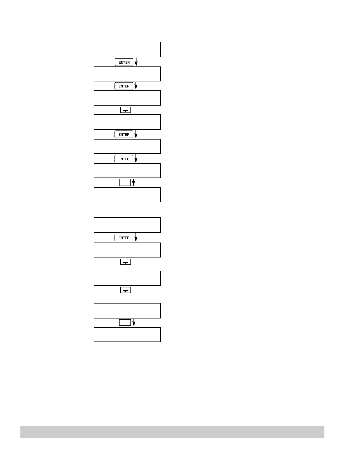
STOP
STOP
ENTER
ENTER
MENU
STOP
MENU
8.2.15
output: Press CLEAR to enable editing and enter a
small negative number (i.e. -0.100) to force a display reading,
then clear and enter small quantity measured on your meter.
The display will return to Calibrate 0mA out. Press the down
arrow key to advance to Cal. 20mA out or repeat above if
necessary.
Connect ammeter to (+) TB1-15, (-) TB1-16. Press enter.
To trim 20mA output: Press CLEAR to enable editing and enter
the current reading that is on the ammeter display. Press
enter.
The display will automatically return to the Calibrate 20mA out
submenu. Calibration is complete.
Press the Menu key to go back to Calibrate top-level menu.
Press enter to test the analog inputs.
To check voltage input accuracy: Use TB1-4 as Reference
Ground, input 0-10 Volts to TB1-2 and/or TB1-5. Display
should show voltage being input. Use voltage meter to verify
input.
To check current input accuracy: Use TB1-4 as Reference
Ground, input 0-20mA to TB1-3 and/or TB1-8. Display should
show current being input. Use ammeter to verify input.
To check RTD input accuracy: Connect a jumper wire between
TB1-6 and TB1-7, Place a 100 ohm 0.1% resistor between
TB1-7 and TB1-8. Display should show 100 ohms ±0.1%.
Press Menu key to return to Analog In Test top-level menu.
Calibrate 4mA Out
Submenu Group
8.2.16
Calibrate 20mA Out
Submenu Group
8.2.17
Analog In Test
Submenu Group
Calibrate 0mA out
+ TB1-15 - TB1-16
ENTER
Calibrate 0mA out
Enter mA: 0.00000
Calibrate 0mAout
+ TB1-15 - TB1-16
Calibrate 20mA out
+ TB1-15 - TB1-16
Calibrate 20mA out
Enter mA: 20.00000
ENTER
Calibrate 20mAout
+ TB1-15 - TB1-16
Calibrate
Connect ammeter to (+) TB1-15, (-) TB1-16. Press enter.
To trim 0mA
Analog In Test
ENTER
Analog In Test Volts
T2:00.000 T5:00.000
Analog In Test mA
T3:00.000 T8:00.000
Analog In Test OHMS
RTD 00.000
Analog In Test
Pg 50 121-000-350 © 2001 Max Machinery, Inc.
Page 51
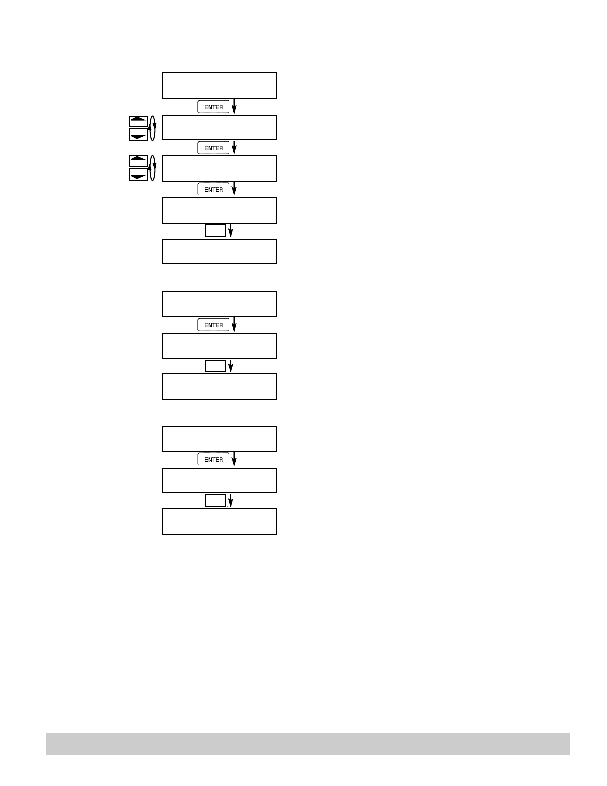
START
ENTER
MENU
MENU
MENU
START
8.2.18
Pulse input test
Submenu Group
Pulse input test
Press Enter key to test the pulse input.
10mV
100mV
3KHz
20kHz
8.2.19
Analog out test
Submenu Group
2.5V
40Hz
STOP
STOP
Pulse input test
Trigger level 2.5V
ENTER
Pulse input test
count speed 3kHz
ENTER
Pulse input test
F1: 0 F2: 0
Pulse input test
Analog out test
ENTER
Analog out test
*0 4 10 15 20 mA
Analog out test
Use the Up/Down arrow keys to select the appropriate trigger
level.
Use the Up/Down arrow keys to select the appropriate frequency range.
To check Pulse input accuracy: Use TB1-4 as reference
ground, input a frequency on TB1-2. The display should show
frequency being input. Use a frequency counter to verify input.
Press Menu key to return to Pulse input test top-level menu.
Press Enter to test the analog output.
To simulate analog output: Connect an ammeter to (+) TB1-15,
(-) TB1-16. Press the key under the desired setting to move
the asterisk (*). The unit should output the selected current.
Press Menu key to return to Analog out test top-level menu.
8.2.20
Excitation out test
Submenu Group
Excitation out test
ENTER
Excitation out test
*5v 12v 24v
Excitation out test
Press Enter to test the excitation output.
To test the excitation output: Connect a voltmeter to (+) TB1-1,
(-) TB1-4. Press the key under the desired setting to move the
asterisk (*). The unit should output the selected voltage.
Press Menu key to return to Excitation out test top-level menu.
121-000-350 © 2001 Max Machinery, Inc. Pg 51
Page 52
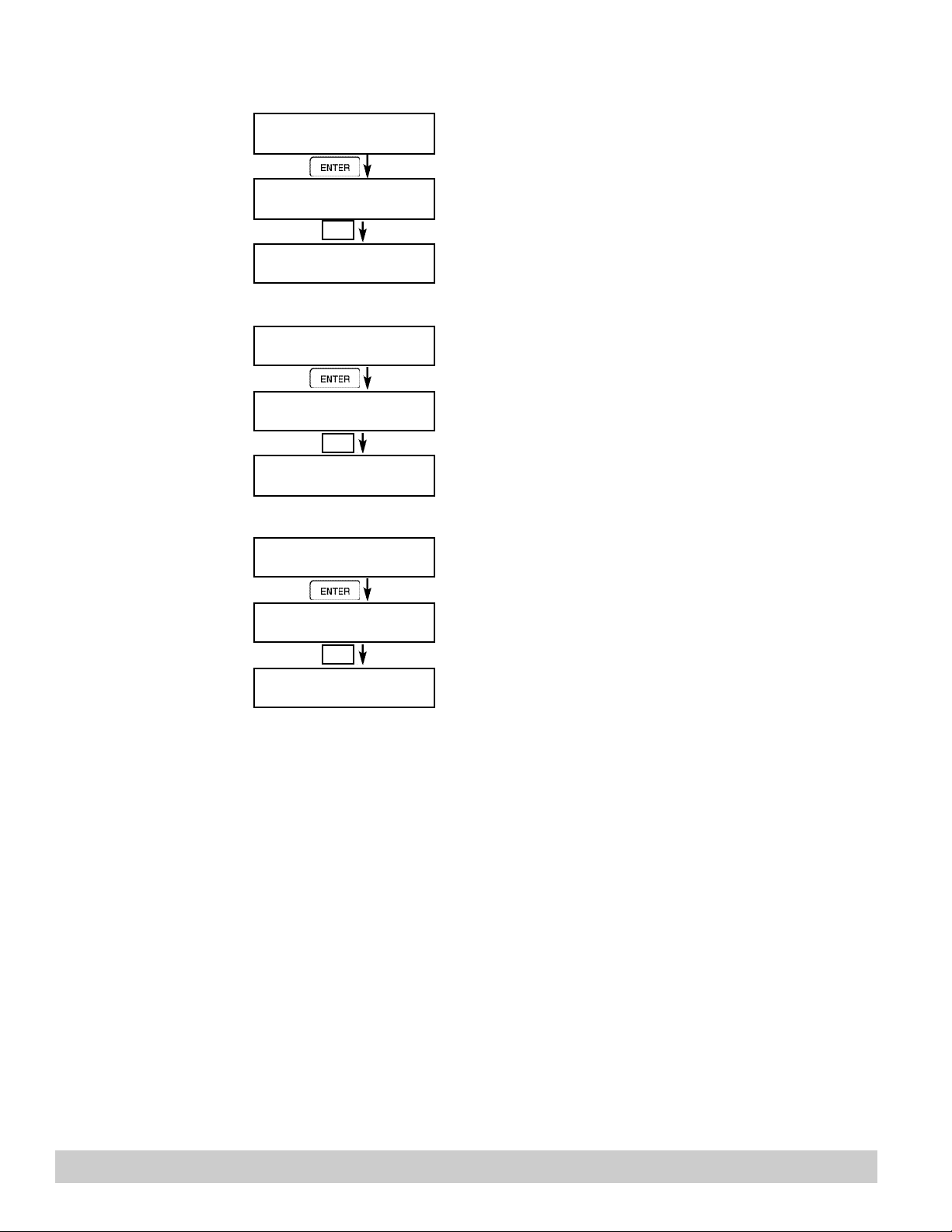
MENU
MENU
MENU
8.2.21
o simulate a frequency on the pulse output: Connect a frequenc
counter to (+)TB1-13,
(-)TB1-14. Press the key under the desired setting to move the
asterisk (*). The unit should output the selected frequency.
Press Menu key to return to Pulse out test top-level menu.
Press Enter to test the relays.
To manually control the relay outputs: Press the key under the
desired relay to toggle the relays On/Off. Use an ohmmeter to
check the relay contacts.
Press Menu key to return to Relay Test top-level menu.
Press Enter to test the control inputs.
To check the control inputs: Use TB1-12 as reference, input a DC
signal to TB1-9, TB1-10 and/or TB1-11, The Display will show O
when input is active, OFF when inactive.
Press Menu key to return to control input test top-level menu.
Pulse out test
Submenu Group
Pulse out test
ENTER
Pulse out test
*0Hz 1Hz 10Hz 20Hz
Pulse out test
Press Enter key to test the pulse output.
T
8.2.22
Relay test
Submenu Group
8.2.23
Control input test
Submenu Group
Relay Test
ENTER
Rly1 Rly2 Rly3 Rly4
O ff Off Off Off
Relay Test
Control inputs test
ENTER
TB1-9 TB1-10 TB1-11
Off Off Off
Control inputs test
Pg 52 121-000-350 © 2001 Max Machinery, Inc.
Page 53
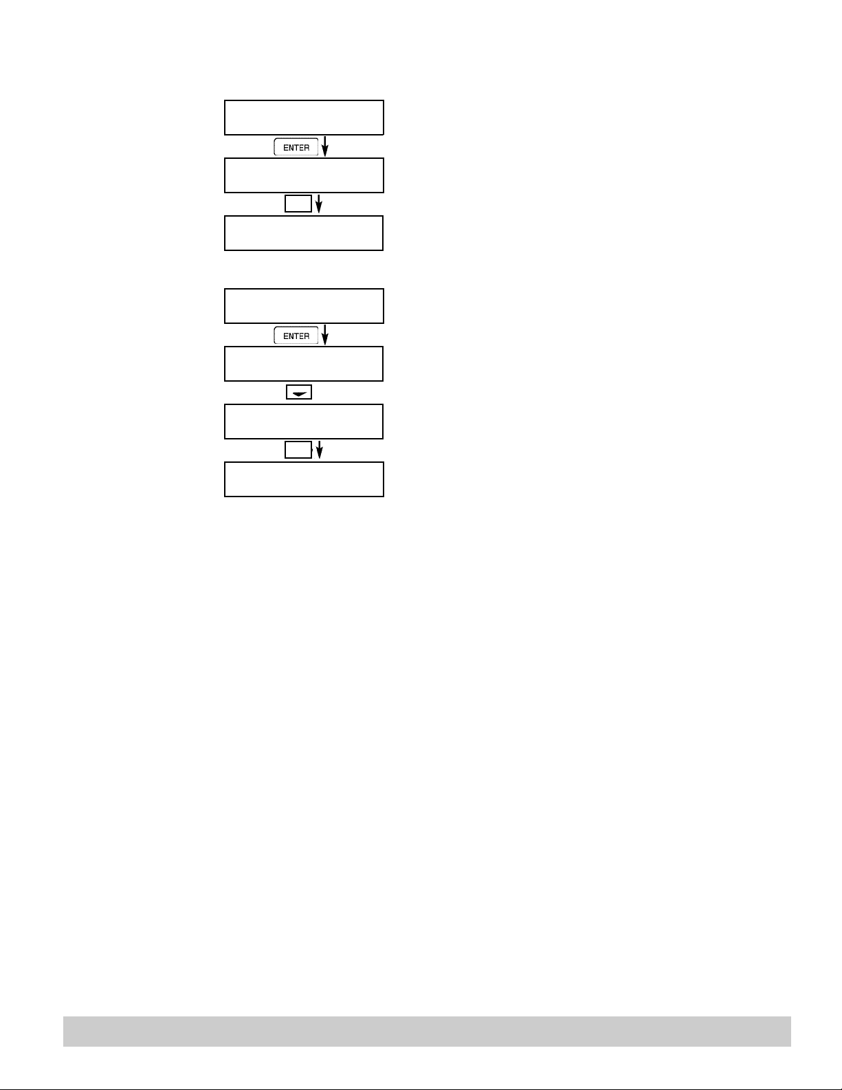
ENTER
STOP
8.2.24
Battery Voltage
test
Submenu Group
Battery Voltage Test
Battery Voltage Test
3.312 Volts
MENU
Battery Voltage Test
Press Enter key to view the battery voltage.
The display will show the battery voltage.
Replace battery at 2.5 VDC or below.
Press Menu key to return to battery voltage test top-level
menu.
8.2.25
Data logger utility
Submenu Group
Data logger utility
ENTER
Data logger utility
Log 10 958 Max
Data logger utility
Log 00001 PRT CLR
MENU
Data logger utility
Press Enter to use data logger utility.
The displays shows the number of Data Logs.
Press the Down arrow key to advance to PRT (print) or
CLR (clear).
Press PRINT key to output data logger logs to printer,
Press CLEAR key to clear the data logger contents.
Press Menu key to return to Data logger utility top-level
menu.
121-000-350 © 2001 Max Machinery, Inc. Pg 53
Page 54
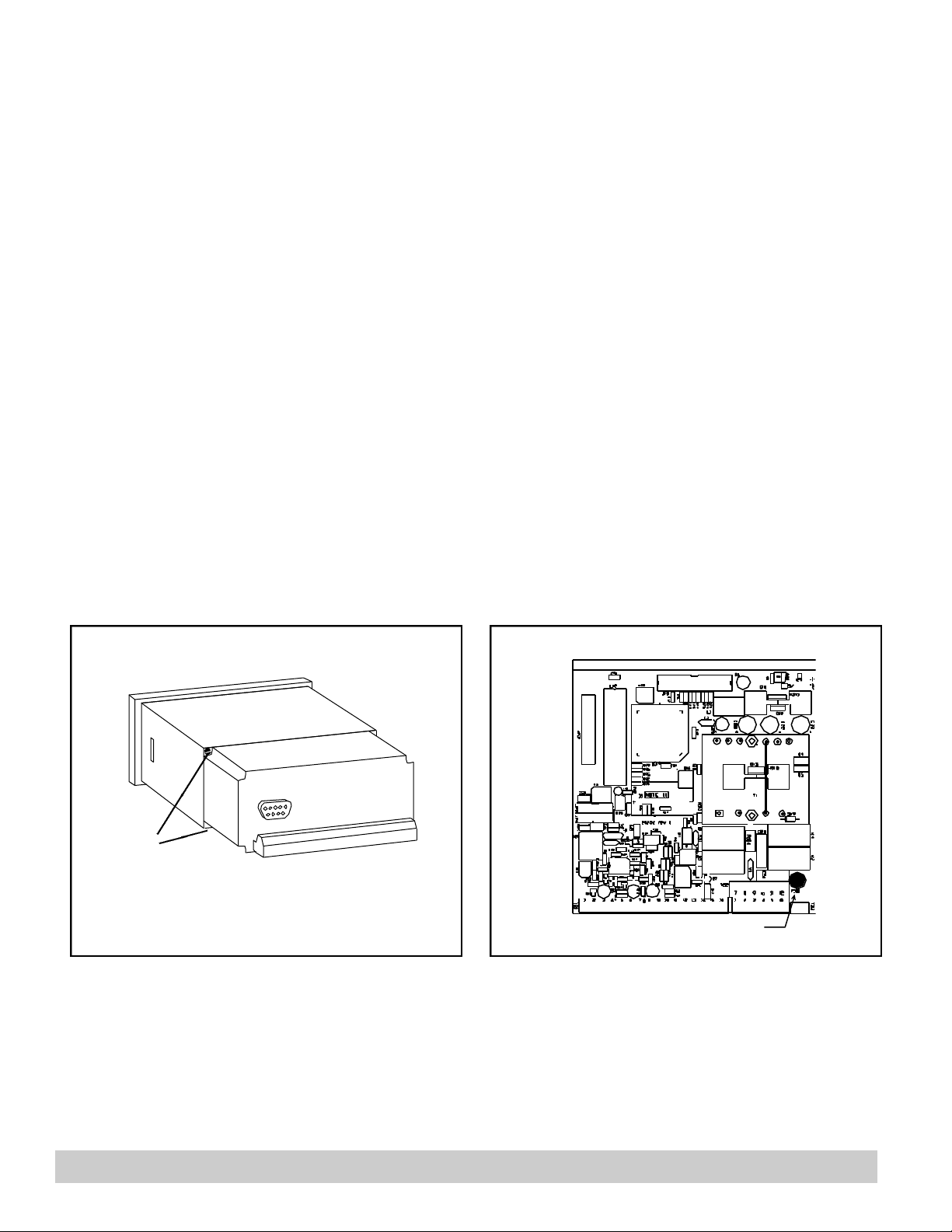
8.3 Internal Fuse Replacement
FUSE
fuse
Instructions:
1. Make sure you follow proper E.S.D. Precautions. All persons performing this replacement must follow proper
grounding procedures.
2. Turn the power to the unit off.
3. Disconnect the two piece connector rear terminal block, leaving all connections in place.
4. Remove the unit from the panel.
5. Remove the four machine screws (see fig. 1) which hold the two sections of the case together.
6. The rear section of the case should detach from the rest of the case. It may be necessary two cut the wiring
label along the joint where the two sections connect. With the rear section of the case removed the fuse will be
exposed (located near the rear terminal, AC connection).
7. Locate the Fuse F1 (see fig. 2) and unplug the fuse from its socket.
8. Insert the new fuse into the socket. Insure that the pins are fully inserted and straight.
9. Reassemble the case and install the four machine screws which join the two sections of the case.
10. Reinstall the unit into the panel.
11. Reconnect the rear terminal block.
12. Turn the unit back on.
Fuse Specifications:
110 VAC Power: 160mA/250V, TD Wickman 19372-030-k or equivalent
220 VAC Power: 80mA/250V, TD Wickman 19372-026-k or equivalent
12/24 VDC Power: 800mA/250V, TD Wickman 19374-046-k or equivalent
Fig. 1 Fig. 2
Screws
(4 places)
Pg 54 121-000-350 © 2001 Max Machinery, Inc.
Page 55
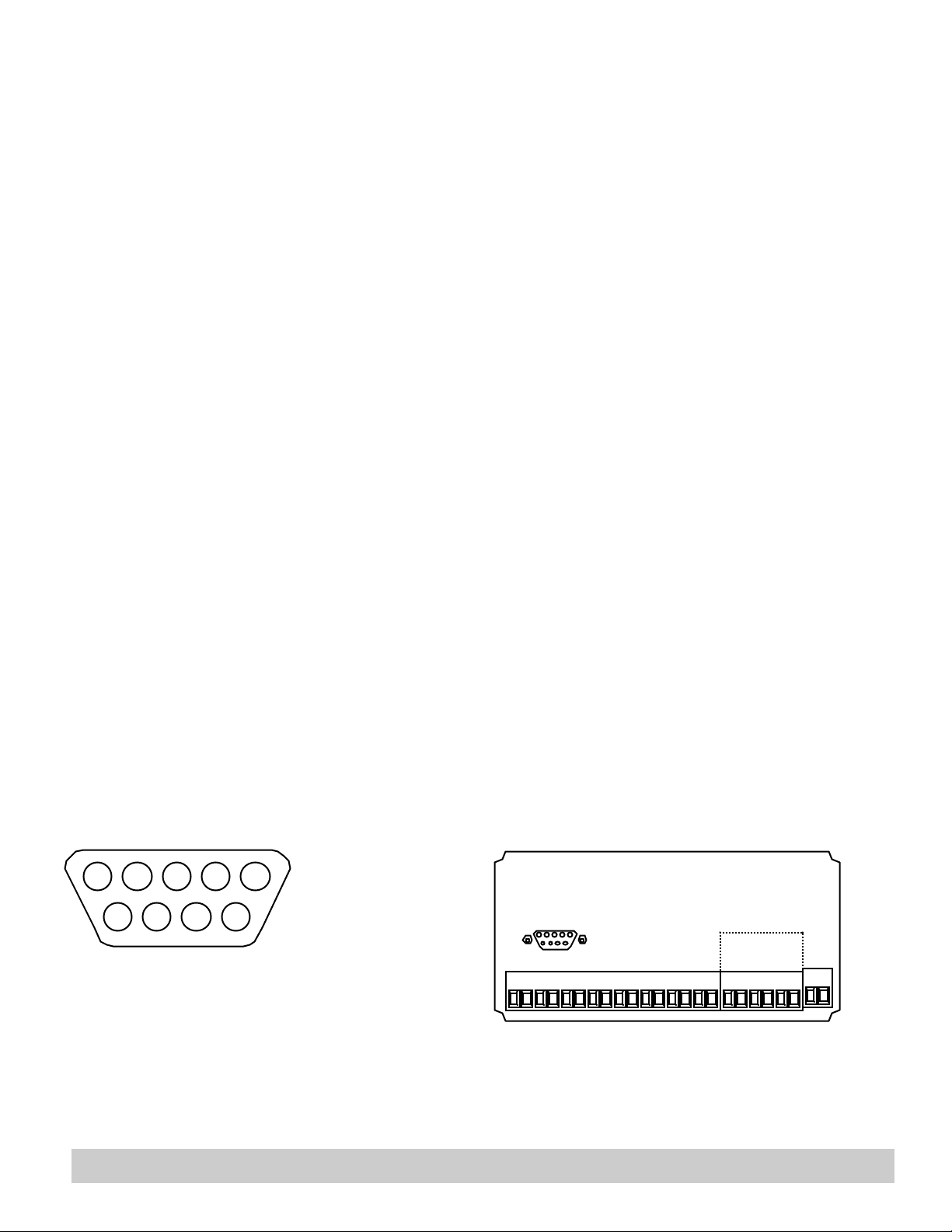
9. RS-232 Serial Port
9.1 RS-232 Port Description:
The Model 121 Series has a general purpose RS-232 Port which may be used for any one of the following purposes:
Transaction Printing
Data Logging
Remote Metering by Modem (optional)
Computer Communication Link
Configuration by Computer
Print System Setup
Print Calibration/Malfunction History
9.2 Instrument Setup by PC’s over Serial Port
A Diskette program is provided with the Model 121 Series that enables the user to rapidly configure the unit using a
Personal Computer. Included on the diskette are common instrument applications which may be used as a starting point for
your application. This permits the user to have an excellent starting point and helps speed the user through the instrument
setup.
9.3 Operation of Serial Communication Port with Printers
The Model 121’s RS-232 channel supports a number of operating modes. One of these modes is intended to support
operation with a printer in metering applications requiring transaction printing, data logging and/or printing of calibration and
maintenance reports.
For transaction printing, the user defines the items to be included in the printed document. The user can also select what
initiates the transaction print generated as part of the setup of the instrument. The transaction document may be initiated via
a front panel key depression, a remote contact closure, or upon completion of a batch.
In data logging, the user defines the items to be included in each data log as a print list. The user can also select when or
how often he wishes a data log to be made. This is done during the setup of the instrument as either a time of day or as a
time interval between logging.
The system setup and maintenance report list all the instrument setup parameters and usage for the current instrument
configuration. In addition, the Audit trail information is presented as well as a status report listing any observed malfunctions
which have not been corrected.
The user initiates the printing of this report at a designated point in the menu by pressing the print key on the front panel.
The user may specify a “next calibration date” for periodic maintenance. The unit will automatically remind the user that
calibration is scheduled during instrument power up and in some printed documents after that date.
9.4 121 Series RS-232 Port Pinout
1 Handshake Line
2 Transmit
3 Receive
4 Do Not Use
5 Ground
6 Do Not Use
8 Do Not Use
9 Do Not Use
12345
6789
RS-232 RS-485
12345
6789
1 2 3 4 5 6 7 8 9 1011 1213 1415 16 17 1819 2021 22
12345
6789
23 24
121-000-350 © 2001 Max Machinery, Inc. Pg 55
Page 56

11. Flow Computer Setup Software
The Model 121 setup program provides for configuring, monitoring and controlling the indicator.
Sample applications are stored in disk files. The setup program calls these Templates. You can store the setup
from the program’s memory to either the Model 121 (Downloading the file) or to a disk file (Saving the file) for
later usage. Similarly you can load the setup in program memory from either a disk file (Opening a file) or from
the Model 121 unit (Uploading a file).
The program can monitor outputs from the unit while it is running.
The program can reset alarms and totalizers.
For assistance there are mini-helps at the bottom of each screen in the program. There is also context sensitive
help available for each screen accessible by pressing the F1 key.
11.1 System Requirements:
IBM PC or compatible with 386 or higher class microprocessor
4 MB RAM
3 MB free disk space
VGA or higher color monitor at 640 x 480
Microsoft® Windows™ 3.1 or 3.11 or Windows 95™
Communication Port - RS-232
RS-232 Cable
11.2 Cable and Wiring Requirements:
The serial communication port on your PC is either a 25 pin or 9 pin connector. No cabling is supplied with the
setup software. A cable must be purchased separately or made by the user. It is recommended to purchase a
modem cable which matches the available communication port on you PC and a 9 pin male connection for the
Model 121 serial port.
11.3 Installation for Windows™ 3.1 or 3.11
The Setup Software includes an installation program which copies the software to your hard drive.
Insert Setup Disk 1 in a floppy drive.
In the Program Manager, click File, and then select Run.
NOTE: For Windows 95™ Click the Start button, select Run and proceed as follows:
Type the floppy drive letter followed by a colon (:) and a backslash (\), and the word setup. For Example:
a:\setup
Follow the instructions on your screen.
11.4 Using the Flow Computer Setup Software
The setup software window consists of several menu “Tabs”. Each tab is organized into groups containing
various configuration and/or monitoring functions. To view the tab windows, simply click on the tab. The
previous tab window will be hidden as the new tab window is brought to the foreground.
Pg 56 121-000-350 © 2001 Max Machinery, Inc.
Page 57

11.5 File Tab
The File Tab has three sections. Any of the options on this tab can also be accessed from the File submenu.
The Template Section provides for opening and saving templates. The Save and Save As buttons provide the
standard Windows functionality for dealing with files. The Load button is used to open existing templates.
There are two additional menu items available only from the File menu: Create new file and Templates.
The Create new file, option allows for creating custom templates using the existing template in memory as the
starting point. Assign a new name for this template. The template will be saved under this new name.
The Template option will bring up a list of predefined templates that can be loaded into the program. These
predefined templates are useful as a starting point when defining custom templates.
A typical scenario using the setup program would be the following:
• Open up a predefined template from the supplied list
• Choose ‘Save As’ to save this to a new file name
• Proceed to customize the template by making any changes that are needed
• Save the template to disk (if you want to reuse this template)
• Download the template to an attached unit.
The Communications with Model 121 Section allows the user to upload a template file from the unit, download
the program’s current template to the unit or Compare the program’s current template with the unit.
The Print (report) Section allows the user to:
1. Configure the current WindowsTMprinter through the Select Printer option.
2. Print a Maintenance Report through the PC's printer using the Print Maintenance option.
3. Print the current template through the PC's printer using Print Setup option.
11.6 Setup Tab
The Setup tab is where majority of the 121 Series instrument setup modifications are done. The Setup tab is
divided into five sections.
NOTE: Many setup items are enabled or disabled depending on previous setup selections, It is important to
System Section: Parameters, Display, Indicators
Input Section: Flow, Fluid, Compensations, Control Inputs
Output Section: Pulse, Currents
Relay Section: Relays
Other Settings Section: Administration, Communication, Printing
work your way through the above list in the order shown. Be sure to verify your selections when you are
through programming to insure that no settings were changed automatically.
121-000-350 © 2001 Max Machinery, Inc. Pg 57
Page 58

11.7 View Tab
sign
in front of the group title. If a group is collapsed and data in the group changes on refresh, the group will
automatically expand. Changing the view items requires stopping the current viewing, checking the new
selections and then restarting the viewer.
If communication errors occur while reading data from the indicator, the word ‘Error’ will appear in
place of the actual value. If the connection to the 121 Series is lost, the viewer will time out with a message
saying the device is not responding.
The viewer will attempt to communicate with the indicator matching the device ID set in the
communications screen. If you are having trouble establishing communication, compare settings for the PC and
the flow computer. Also verify the connections between the PC and flow computer.
11.8 Misc. Tab
This tab has three sections: Tools, Actions and Options.
The tools section contains various system administration activities such as creating/modifying the initial sign-on
screen or calibration, service test etc.
Create Sign-on, Create Print Header, Calibration, Service Test
The Actions section is used to send commands to the Model 121.
Reset Totalizers, Reset Alarms
The Options section has the following selections:
Linearization, PC Communication
Additional capabilities may be provided in the future.
NOTE: Future options appear as disabled buttons on the screen.
The View Tab screen allows for viewing selected group items on the PC in a similar format as shown on
the unit display. Data from the following groups can be viewed in the List of Values section:
Process Parameters (i.e. rate, temperature)
Totalizers (i.e. total, grand total)
The setup software assumes the current setup has been uploaded from the flow computer into the PC. It is
important that the setup program and the Model 121 unit are using the same setup information at all times or
the data will be inconsistent. It is best to upload or download the setup before using this feature.
To start the viewer, first check the boxes of items to view and then click the start button. The data will appear in
the appropriate sections and will be continuously updated. The refresh rate is dependent on the number of items
that are being viewed and the baud rate of the connection. Data in the List of Values section can be collapsed
by clicking on the ‘minus’ sign in front of the group title. The data can be expanded by clicking on the ‘plus’
Pg 58 121-000-350 © 2001 Max Machinery, Inc.
Page 59

12. Glossary Of Terms
Alarms will
reassert themselves if alarm conditions are still present.
Analog Output
The analog signal (4-20mA) that is generated by the Model 121. It can correspond to the Rate, Total, Temperature or
Density. This output is used primarily for transmission of process information to remote systems.
Audit Trail
The audit trail is used to track the number of changes made to the units setup program.
Auto Batch Restart
The Auto Batch Restart function allows the user to set an amount of time to automatically restart a batch after the
completion of a batch. This time can be set from 1 to 99 seconds.
Batch Count Mode
Batch Count Mode specifies the user preference for count direction. The "Up" selection begins with a value of "0" and
counts up until the batch size is reached. The "Down" selection begins with a value equal to the desired batch size and
counts down to "0".
Batch Overrun
The Model 121 offers a batch overrun compensation routine. If batch overrun occurs due to slow valve response time, the
unit will compensate for the overrun amount on the next batch. This feature can be disabled if desired.
Batcher
An instrument which controls the dispensing of desired batch amounts. Liquid batching systems are usually comprised of a
batch controller (batcher), flowmeter and control valve. The batcher opens and closes the valve through the use of relays
and measures the amounts of liquid being dispensed via the flowmeter.
Baud Rate
The speed of serial communication transmissions, expressed in bits per second.
C-Factor (Fluid Expansion Factor)
A parameter in a flow equation which is used to describe the relationship between density or volume and temperature
changes.
Corrected Volume Flow
The equivalent volume at a reference temperature condition which involves the measurement of liquid volume flow using a
flow sensor and temperature sensor to compensate for thermal expansion.
Custody Transfer
Weights and Measure metering codes often specify several requirements for instruments and mechanisms to prevent and
track changes in the setup of an instrument which may be used in the commercial sale of goods. The Model 121 tracks
changes via the Audit Trail.
Data Logger
The capturing of information for printing out later use and the mechanism for specifying the conditions where a capture
should be made.
DC Output / Excitation Voltage
An on-board DC power supply used to power peripheral sensors. The Model 121 offers excitation voltages of 5VDC, 12VDC
or 24VDC when powered by AC voltage.
Default Value
The value to be used by the instrument if a sensor failure or out of range signal is detected.
Expansion Factor
See C-Factor
Flow Alarm
A visual indication that the volumetric flowrate is above or below the flow alarm setpoint specified by the user.
Acknowledge & Clear Alarms
Acknowledge is used to clear alarm relays and remove any visual alarm messages from the display. In the run mode, press
the ENTER key or activate CONTROL INPUT 3 (if set for ACK) to momentarily clear alarms and alarm messages.
121-000-350 © 2001 Max Machinery, Inc. Pg 59
Page 60

12. Glossary Of Terms (Continued)
means of controlling the information flow between two pieces of equipment to prevent the sending device from transmitting
information at a rate faster than what can be accepted by the receiver.
Hysteresis
The relay hysteresis is a "dead band" setting which allows the relay to remain energized for a given amount below the
setpoint. This is used to prevent relay chatter when the process value is near the setpoint value.
Example: If the Preset is set at 100, and the hysteresis is set at 10, the relay will energize when the rate, temp or dens.
reaches 100, the relay will remain energized until the reading falls below 90.
Input Termination
Input signal lines on digital inputs often require pullup or pulldown resistor configurations to operate properly with different
sensor configurations. The Model 121 contains such resistors and may be enabled via the setup menu.
Inhibit Totalizer
"Inhibit Total" is a Control Input 1 setting that is used to stop the totalization. If enabled, a voltage level on control input 1 will
inhibit the total as long as the voltage is present. This feature is useful during meter proving and in applications that provide a
sensor to signal the flow computer when fluid is present.
K-Factor
A scaling factor derived from the pulses produced by a flowmeter output, expressed in pulses per unit (i.e. pulses/gallon)
Limit Setpoint
An alarm trip point setting which specifies the value or magnitude of a process parameter necessary to activate an alarm
indicator or control relay.
Linear Flowmeter
A flow measurement device whose output is proportional to flow.
Linearization
The mathematical correction of a nonlinear device. The Model 121 uses a linearization Table which is made up of
input/output values and makes interpolations of the table to arrive at a "linearized" measurement.
LinTbl
Abbreviation for Linearization Table.
Low Flow Cutoff
A value set at which any flow measurements read below this value will be ignored.
Low Pass Filter
A low pass filter passes low input frequencies while blocking high frequencies. In the Model 121, this is the maximum input
count speed to be encountered in an application. It is expressed in counts per second (Hz).
Mass Flow
Mass Flow is inferred by the volumetric flow and density (or implied density) of a fluid.
Flow Signal Timeout
Flow Equation
Follow, Alarm
Function Key
Handshake
The Flow Signal Timeout allows the user to enter a timeout of 0 to 99 seconds. If a batch is “Filling” and zero flow persists for
more than the user entered time then the batch will be aborted. This prevents over flows due to faulty flow sensors and/or wiring.
A flow control expression or algorithm describing a mathematical equation to be solved by a flow computer in the desired
application.
Alarm relays which are non latching and whose output state is based solely on the comparison of the current process value
and the alarm setpoint (trip point).
A key on a push-button panel or keyboard (whose function is described by the key label) used to perform an instrument
function or special routine.
A
Pg 60 121-000-350 © 2001 Max Machinery, Inc.
Page 61

12. Glossary Of Terms (Continued)
.
Max Window
The max. window time sets the maximum sample time (1 to 99 sec) for the ratemeter.
Modem Init Master
The "Modem Init Master" menu allows the user to select whether the unit will engage in a configuration conversation with the
modem on power up or impart no setup information to the modem and use it "as is". For most users it is recommended to
choose "yes" for "Modem Init Master".
Parity
A method for detecting errors in transmissions of serial communications data.
Preset
A set point used to trigger the relay outputs of the 121 Series.
Print Interval
The print interval allows the 121 Series to transmit information to the serial port at selectable time intervals.
Private Code
An operator password code which authorizes changes to the setup of the instrument but blocks access to the
Service/Calibration/Test mode. The private code also blocks the clearing of the Grand Total.
Process Parameters
Any sensor information which has been scaled to engineering units including Flow, Temperature and Density.
Pulldown (Input Termination)
The termination of an input at which the input is pulled down to ground through a resistor. Inputs that are terminated by this
method need to be driven high with a positive voltage pulse.
Pullup (Input Termination)
The termination of an input at which the input is pulled up to a positive voltage through a resistor. Inputs that are terminated
by this method need to be pulled low with a sinking current or contact to ground .
Pulse Output
The pulse output of the 121 Series is available for remote accumulation of the total or sent to peripheral devices, such as a
PLC. The output can be scaled using the Pulse Output Scaling Constant.
Quad
Abbreviation for Quadrature. Quadrature signals are used for direction control. Two flowmeter signals are output with a 90°
phase shift. The counter counts UP when channel Aprecedes channel B, and counts DOWN when Channel A lags Channel B.
Quick Setup
A utility that provides for rapid configuration of an instrument. The Model 121 quick setup provides the following:
1) Prompts the user for only critical information.
2) Automatically sets specifications to common uses.
After following the Quick Setup procedure, the unit will be operational to perform the basic measurement. The setup can be
further customized using the setup menus.
Maximum Batch Preset
The Maximum Batch Preset allows the user to program the Maximum Batch value allowed to be entered by the operator. If
an operator should try to program a batch higher then this value, the unit will not allow the value to be entered and will
prompt the user with an error message saying that the Maximum Batch Preset has been exceeded.
Maximum Drain Time
The unit declares that a batch is “done” when the flow rate equals “0”. A flow rate may be present long after the Preset Relay
de-energizes due to slow reacting valves or leaky valves. The Maximum Drain Time allows the user to enter an amount of
time (0 to 99 seconds) to wait before declaring “Batch Done”. After the Preset Batch quantity is reached, the unit will declare
“Batch Done” when the flow rate is “0” or the Maximum Drain Time has expired. The batch data will then be available for printing and datalogging
121-000-350 © 2001 Max Machinery, Inc. Pg 61
Page 62

12. Glossary Of Terms (Continued)
.
Rate Averaging Filter
The rate averaging filter is used to stabilize fluctuating rate displays. Higher settings provide more averaging for a more sta-
ble display. Derived from the equation:
(OLD DATA x "Avg. Filter" + NEW DATA)
("Avg. Filter" + 1)
Ratemeter
Any device used to display the speed of a process. The ratemeter in the Model121 Series displays flow rate.
Ref. Dens.
Abbreviation for Reference Density. This is the fluid density at reference temperature.
Ref. Temp.
Abbreviation for Reference Temperature. This represents the base or reference condition to which corrected flow will be computed.
Reset/Start Control Input
In a batching system, a single operator activation of the ST A RTkey or Control Input 1 will reset the total then start the batch process.
Single_Pulse
The Single_Pulse setting is used for flowmeters with single pulse outputs.
Slow Start Quantity
The Slow Start Quantity is a function that allows an amount to be entered for a Slow Start up. This function requires two
stage valve control. RLY 1 (slow flow) will energize for Slow Start and RLY 2 (fast flow) will energize after the Slow Start
Quantity has been delivered. This helps reduce turbulence when filling an empty container.
Sqrt
Abbreviation for Square Root Extraction. Used for flow elements using differential pressure measurements.
Stop/Reset Control Input
In a batching system, a single operator activation of the STOP key or Control Input 2 will stop the batch process then reset
the total.
Time Constant
A damping factor for an averaging filter for the analog output. (see also Rate Averaging Filter)
Totalizer
Any device which accumulates and displays a total count.
UVC
Abbreviation for Universal Viscosity Curve. Apresentation of the combined flowrate/viscosity calibration for a turbine flowmeter.
VFD
Abbreviation for Vacuum Fluorescent Display
Visc Coef
Abbreviation for Viscosity Coefficient. One or more coefficients in an equation used to describe the viscosity as a function of
temperature for a fluid.
Volume Flow
The measurement of volumetric flow.
Quick Update %
This feature is used to disable the rate averaging filter when a significant change in the flow rate occurs. The user can enter the
percent of change needed to be detected to disable the averaging feature. This is especially useful during start-up and shutdown of flow
Pg 62 121-000-350 © 2001 Max Machinery, Inc.
Page 63

13. Diagnosis and Troubleshooting
Alarms may reassert themselves if the alarm condition is still
present.
NOTE: A historical error alarm log is available in the "Test Mode".
The following descriptions suggest possible causes and corrective actions for each alarm message.
TYPE OF ERROR DESCRIPTION
Sensor/Process Alarms
Errors detected due to sensor
failure or process alarm conditions
Self Test Errors
Errors detected during self test.
System Alarms
Errors detected due to system
failure
13.1 Response of Model 121 on Error or Alarm:
Error and warning indications which occur during operation are indicated in the RUN mode alternately with the
measured values. The Model 121 Flow Computer has three types of error:
Some alarms are self clearing. Other alarms require the user to acknowledge and clear the alarm. Press the
ENTER button to acknowledged and clear alarms.
121-000-350 © 2001 Max Machinery, Inc. Pg 63
Page 64
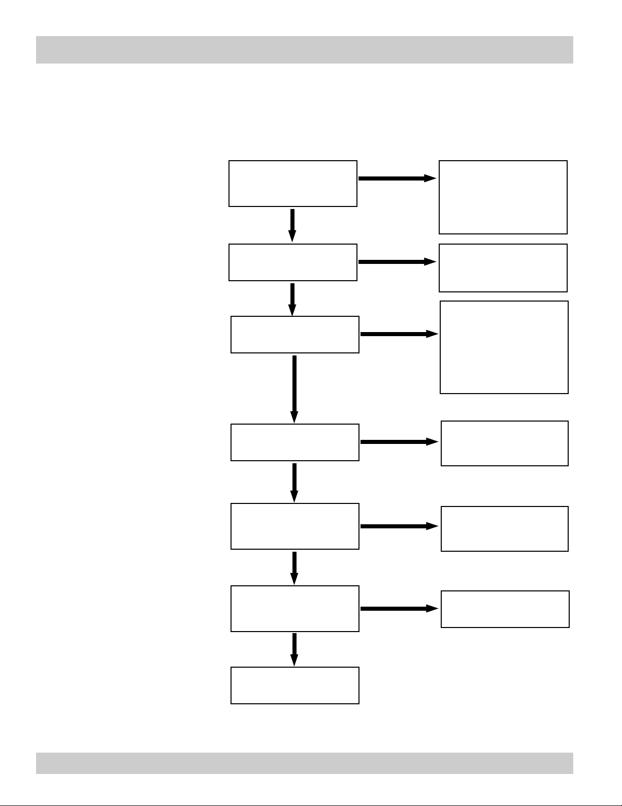
13.2 Diagnosis Flow Chart and Troubleshooting
A summary of possible causes is given below to help you identify faults.
Is there an input power
supply voltage across
Terminals 23 and 24?
Yes
Is the Display Backlight
Visible?
Yes
Are the Display
Characters Visible?
Yes
Is there a black bar
across the display?
No
No
No
No
Yes
Check the connections
according to the circuit
diagrams.
Check junction box fuses.
Check/Replace internal
fuse. If fuse is OK,
Factory Service Required.
The display may not be
visible with ambient
temperatures below -10 °C
Allow the instrument to
warm up.
Contact factory if
necessary
Check line voltage.
If voltage is OK,
Factory Service Required.
Does the display
alternate between blank
and sign on message? Yes
Check line voltage.
If voltage is OK,
Factory Service Required.
No
Does the display show
an error message?
Yes
See section 12.3 for
cause and remedy.
No
No system or process
errors present.
Pg 64 121-000-350 © 2001 Max Machinery, Inc.
Page 65

13.2 Diagnosis Flow Chart and Troubleshooting
13.3.1
Sensor/Process Alarms
Error/Warning Message
Cause
Remedy
TOTALIZER ROLLOVER
AUX INPUT TOO LOW
RTD OUT OF RANGE
RATE OVERFLOW ERROR
PULSE OUT OVERFLOW
FLOW RATE ALARM LOW
FLOW RATE ALARM HIGH
TEMP ALARM LOW
TEMP ALARM HIGH
DENSITY ALARM LOW
DENSITY ALARM HIGH
Displayed when totalizer
rolls over
4-20 mA Input current at
aux input smaller than 3.5
mA:
• Faulty Wiring
• Transmitter not set to "420 mA"
• Transmitter defective
Input current at RTD input
too low:
• Faulty wiring
• RTD defective
Pulse counter overflowed.
The totalizer may have lost
counts.
Calculated pulse frequency
too large:
• Pulse width setting too
long
• Larger pulse scaler needed
Limit value exceeded.
Acknowledge
Rollover,
Remedy not required
• Check wiring
• Check function of sensor
• Check wiring
• Check function of RTD
sensor
• Report error to factory
• Check application conditions
• Check wiring
• Adjust pulse value
• Adjust pulse width
• Check process conditions
• Check application if necessary
• Check limit value
• Adjust the limit value if
required
BATCH OVERRUN ALARM
MODEM NOT PRESENT
SOFTWARE ERROR
RESET
EXTENDED PFI LOCKUP
Batch size exceeded by
more than set limit.
The setup expects modem
usage and a modem is not
responding.
Abnormal program termination may have occurred as a
result of power transient.
Unit was operated with an
input power level lower than
safe operating range for an
extended period of time.
• Check valves in system for
proper operation and/or leaks
• Check limit value
• Adjust the limit value if required
• Check setup for proper
baud rate, parity, etc.
• Check modem connection
and cycle power
• Replace modem
• Clear error
• Verify instrument setup
• Cycle power
• Additional filtering may be
required on power input
• Check data in unit.
Totalizer may have inaccuracies
• Investigate brownout cause.
121-000-350 © 2001 Max Machinery, Inc. Pg 65
Page 66

13.2 Diagnosis Flow Chart and Troubleshooting
13.3.2
Self Test Alarms
Error/Warning Message
Cause
Remedy
FLOW INPUT TOO HIGH
AUX INPUT TOO HIGH
FLOW INPUT TOO LOW
BATTERY LOW WARNING
A to D NOT CONVERTING
Analog input signal of the
flow input exceeded by
more than 3%:
• Sensor overranged
• Incorrect full scale setting
of flowmeter
• Function error in transmitter or faulty wiring
Analog input signal of the
auxiliary input exceeded by
more than 3%:
• Sensor overranged
• Incorrect full scale setting
of transmitter
• Function error in transmitter or faulty wiring
Analog input signal of the
flow input fell below the low
scale range by more than
3% of full scale value:
• Flowmeter not set to 4-20
mA
• Function error in transmitter or faulty wiring
Battery voltage too low
Fault in analog/digital converter
• Check analog signal range
• Check the application conditions
• Check wiring
• Check analog signal range
• Check the application conditions
• Check wiring
• Check wiring
• Check calibration of
flowmeter
• Check function of flowmeter
• Replace Battery
• Consult Factory for service
information
• Unit may self correct,
Press ENTER to acknowledge & clear alarm
• If error reasserts, factory
service is required
TIME CLOCK ERROR
CAL CHECKSUM ERROR
SETUP CHECKSUM
ERROR
The correct time/date is no
longer shown
Calibration constants have
been corrupted
The units setup has been
corrupted
• Re-enter time and date.
• If error occurs again contact factory
• Report error to factory
• Report error to factory
Pg 66 121-000-350 © 2001 Max Machinery, Inc.
 Loading...