


Discontinued
INSTRUCTION MANUAL
286-300 SERIES TRANSMITTERS
286-
313: Transmitter with Amphenol Connector
286-
323: Transmitter, Weather-Tight, Explosion Proof*
286-
3x4:
Transmitter with Output Level Shifter Option
286-31x-
General Description...................................................
Specifications............................................................
Mechanical Installation.............................................
Outputs, Options, and Indicators...............................
Calibration.................................................................Pg 9
Maximum Transmission Distance.............................
K-
factors....................................................................
Appendix A: Remote Mount Transmitter .................
Appendix B: Output Level Shifter Option................
Schematics:
5xx: Transmitter with Remote PCA
286-313181-000-
TABLE OF
201 RVDT Schematic
250 Interconnect Schematic
CONTENTS
Pg 2
Pg 3
Pg 4
Pg 6
Pg 11
Pg 13
Pg 14
Pg 16
-5
-8
-10
-12
-15
* U.L. Class I, Group C & D
Class II, Group E, F & G
286-300-
nd
2
Max Machinery, Inc.
performance, reliability, or manufacturability. Contact
performance data.
Although every effort h
manual,
MMI
assumes no responsibility for inadvertent errors.
reserves the right to make changes to the product in this instruction manual to improve
as been made to ensure accuracy of the information contained in this instruction
350 © 2002,
Rev: 4/03, added Appendix A and B
Max Machinery, Inc.
MMI
for the latest available specifications and

Discontinued
General Description
General Description
The 286Meter into a frequency proportional to the flow rate. This is accomplished using a differential transformer
technique, which puts no torque requirements on the flow measuring elements and enables extremely fast
output response rates. A microprocessor measures position changes of the metering elements and generates
the corresponding output pulse stream.
When used with the
variations in rotational velocity of
output frequency.
The 286This simplifies matching of flow meter and transmit
The Model 286 features an antidither output buffer. If the flow reverses (for less than ½ revolution of
the flow meter), and then returns to the forward direction, the transmitter pulse output will represent only
the total forward flow. The two-phase output is not buffered; it is an instantaneous indicator of metering
element position. The antidithering is a useful feature when the flow stops or is very low, and vibration or
hydraulic noise causes th
3XX Series Transmitter converts the rotary motion of the metering elements insi
3XX Series circuitry has self
de a
Max
Series 210 Piston Flow Meters, these transmitters will compensate for cyclical
the metering pistons (inherent in the four piston design) to give a steady
-calibration routines that can be initiated with the push of a button.
ter in the event that field maintenance is required.
e flow metering elements to reverse direction.
Max
Flow
The transmitter can be powered from a 4.5V to 30VDC supply. The user can select between two types
of outputs: a square wave output or a two
square wave output. The user can select from square wave outputs of 24, 50, 100, 200, 300, 500, 600 or
1000 pulses per revolution, or two-phase outputs of 12, 25, 50, 100, 150, 250, 300 or 500 pulses per
revolution (on each phase).
-phase output where the frequency of each phase is half that of th
e
(2)
286-300-
350 © 2002,
Max Machinery, Inc.

Discontinued
Specifications
Specifications
Supply Voltage........................................................................
Supply Current....................................
Output
Maximum Rotor RPM...........................................................................
Minimum Rotor RPM..................................................................................
Pulse Width Variation
Output Lag
Ambient Temper
Estimated Microprocessor Memory Lifetime
Antidither Range
(5.0V Supply) ..........................................................................................Hi Lo
No Load..............................................................................................
2.5k Load to Common........................................................................ 4.60 V 0.04 V
2.5k Load to +5 Volts.........................................................................
Short Circuit Current
Output Impedance...............................................................................100
Rise Time ...............................................................................
Fall Time................................................................................
Maximum Frequency .........................................................................
Minimum Frequency..............................................................................
2
................................................................................................
Electronics
Stator .......................................................................
80°C....................................................................................................
55°C and below................................................................................
Pulse Output..........................................................................
Switching of Pin #6
4.5 VDC to 30 VDC
12mA Typical, 20mA Maximum (+ Load)
1
.........................................................................
0.15 uS (90%)
0.15 uS (90%)
3600 RPM
(between consecutive rising edges) ..................
ature Limits
Storage........................................................................-40°C to 85°C
Operation....................................................................-40°C to 80°C
3
-40°C to 130°C (265°F)
4
1/2 Revolution
………………………………………….1/4 Revolution
4.80 V 0.04 V
4.80 V 0.25 V
45 mA
60 kHz
0 RPM
15% max
0.25 mS
20 yrs.
>50 yrs.
0 Hz
1
Continuous Short Circuit is not recommended. The sum of output currents during operation should not exceed 30 mA (i
mA on one output or 15 mA on two outputs).
2
Events are seen as output transitions 0.25 mS after they occur
3
Temperature of metered fluid will affect transmitter temperature, see pg. 4
4
See pg. 8 for more information
286-300-
350 © 2002,
Max Machinery, Inc.
.e.: 30
(3)
Discontinued
Mechanical Installation
Installation
Mounting:
the starting point of the threads, one transmitter will probably not line up with the “in” and “out”
flow meter like another will. The electrical outlet of the transmitter can be rotated clockwise or counter
clockwise one turn by loosening the clamping screw. See the Transmitter Diagram (
Two flats are provided for installing the transmitter on the flow meter. Care should be taken when installing
and removing the transmitter. The wire of the stator is of fine gauge and can be easily damaged.
Moisture Protection:
circuitry enclosed in a liquid-tight and vapora weather tight condition is desired, either the Amphenol or the weatherwill work. To
explosion proof transmitter is required, a potted seal fitting must be used.
If a transmitter is located outside and is not properly sealed, moisture may form
will cause the circuitry to give an inaccurate output or, in some cases, no output at all. In the long run, this
will cause corrosion and failure.
The Model 286 transmitter screws on and off of the flow meter. Due to the random location of
The Amphenol and the weather-
seal the weather-tight transmitter, pipe dope must be used on the liquid
ports of the
next page
tight, explosion-proof transmitte
tight enclosure. All joints are sealed by welding or O-rings. If
tight, explosion
-tight conduit. If an
inside the housing. This
).
rs both have their
-proof transmitter
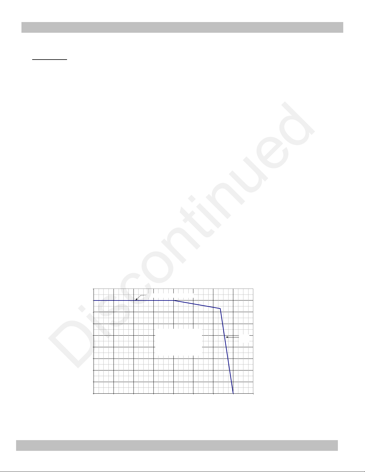
Temperature Considerations: High ambient temperatures (> 120°F/ 50°C) should
It is a good idea to locate the transmitter away from hot spots such as steam pipes, ovens and heaters. The
electronics of the 286 Series Transmitters are rated for operation up to 80° C (175° F). Because some heat
travels from
function of both the ambient and the flow meter temperature. The graph below shows the relation between
the maximum ambient transmitter temperature and the flu
the flow meter to the transmitter electrical enclosure, the temperature of the electronics is a
id temperature through the flow meter.
Transmitter High Temperature Limits
90
80
70
60
50
40
Ambient Temp (°C)
30
20
10
0
0
20 40 60 80 100 120 140 160
Limit for Transmitter Electronics
SAFE
OPERATING
REGION
Flow Meter Fluid Temp (°C)
Stator
Limit
be avoided if possible.
The stator of the 286 transmitters is insulated with an electrical coating that is rated to 130°C which limits
the maximum flow meter fluid temperature to about 130°C (265°F).
(4)
286-300-
350 © 2002,
Max Machinery, Inc.

Discontinued
Mechanical Installation
Transmitter Diagram
Retaining
Ring
O-Ring
O-Ring
Connector
1/
2" NPT or
Weather tight
Amphenol
Circuit Board
Clamp Screw
LOOSEN TO ROTATE
ELECTRICAL HOUSING
Stator Assembly
O-Ring
Wrench Flats
Rotor Assembly
Transmitter - Flowmeter
Threaded Connection
210 Series
Flow Meter
IN
(5)
286-300-
350 © 2002,
Max Machinery, Inc.

Discontinued
Options & Stat
Outputs, Options & Indicators
Outputs, Options and Indicators
Connections:
The interconnect drawing number 181
information on interfacing to Max signal conditioners and indicators.
Output Protection:
Voltage should no
accidentally applied to an output, resistors and diodes will protect the circuitry. Higher voltages will
destroy the resistors and/or diodes.
Grounding:
S1-1: This
S1
-2: This switch, (labeled FILTER) connects Common and Case through two back-to-
capacitors.
By using either S1-1 or S1
system is not grounded at the indicator or if the flowmeter is not physically grounded through its
plumbing, use S1
noise between the case and the trans
problems. To activate either switch, depress the side that is numbered on the switch (and labeled
‘GND’ or ‘FILTER’ on the printed circuit board).
us Indicators
t be applied to any output (terminals 4, 5, and 6). If a low voltage,
switch, (labeled GND) connects Common and Case directly together.
-2, the effects of electrical noise on the transmitter ca
-1. If the system is grounded at the indicator, use S1-2. This allows electrical
-000-250 at the end of this manual provides detailed
n be reduced. If the
mitter circuitry to be reduced without causing ground loop
5V or less, is
back 15 uF
Meter Selection:
S4-1: Depress side that cor
Flow Meters, and 220/240 is for
When used with
constant rotationa
rate. If this switch is placed in the wrong position (for either a 210 or 220/240 meter), the output
frequency will oscillate
Two
-Phase or Square Wave Select:
S4
-2: Depress side that corresponds to desired output. ‘2PH’ gives a 2with the two phases separated by 90° (Ph A on Terminal 5 and Ph B on Terminal 6). The ‘COMB
OUT’ setting gi
a single output of double the frequency (Combined Output on Terminal 4, Direction on Terminal 6).
If S4-2 is set wrong, an unexpected output signal will result since the
for the two distinct output options (see chart below).
responds to meter type. The 210 setting is for
Max
Series 220 Gear and 240 Helix meters.
Max
Series 210 Piston Flow Meters, the Model 286 will compensate for the non
l velocity of the crankshaft, yielding a steady output frequency at a constant flow
20% about its nominal value, four cycles per
ves a single square wave output that combines the information in the two phases into
Terminal Output Signals vs. S4-2 Setting
Connector
Terminal(s)
4,5
6
S4-2 = 'COMB OUT'
(combined output)
Pulse Output
Direction
S4-2 = '2Ph'
(2-phase output)
Phase A
Phase B
Max
Series 210 Piston
revolution.
phase quadrature output
same output circuitry is used
-
(6)
286-300-
350 © 2002,
Max Machinery, Inc.

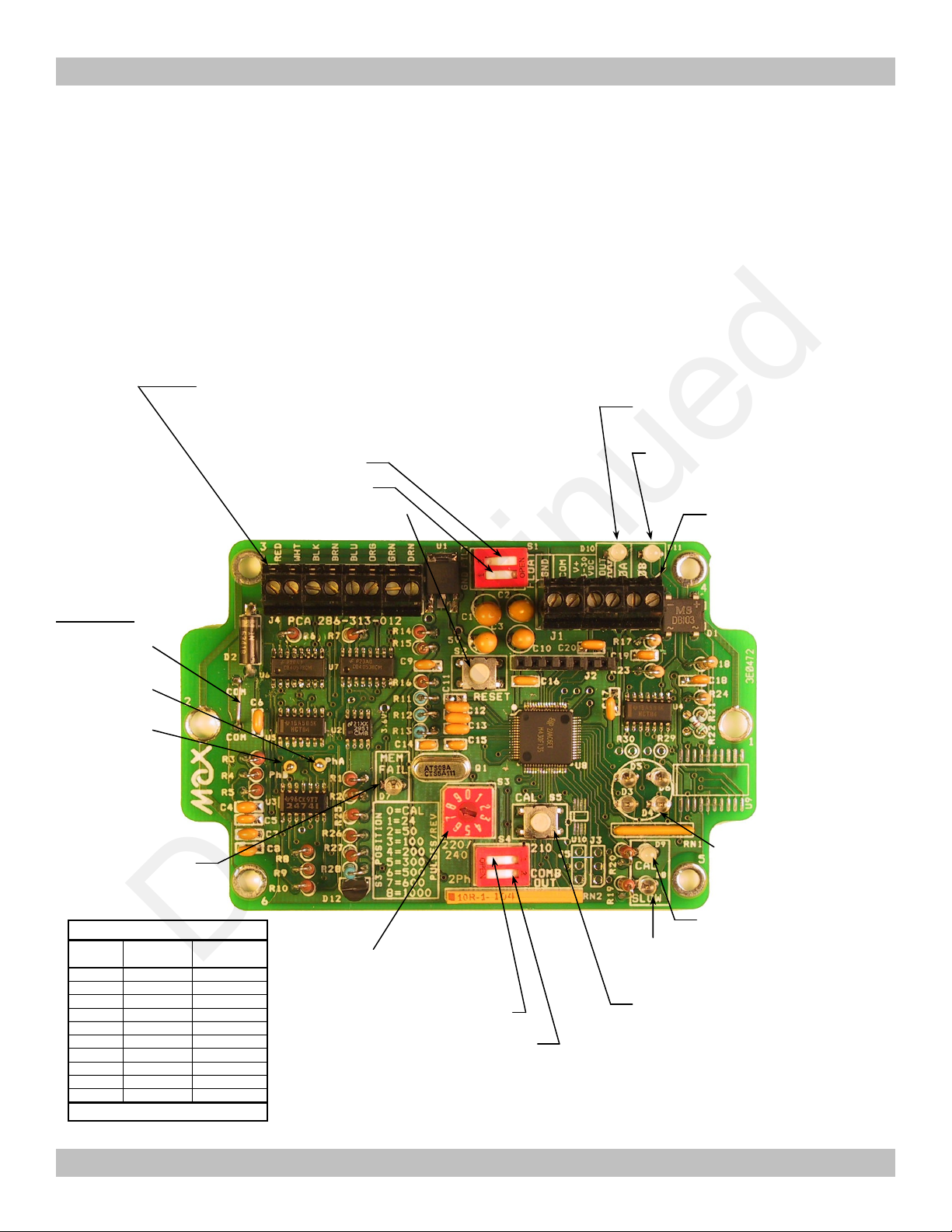
D10
D11
S4-2:
S5:
S3:
Output Frequency Select
D7
S4-1:
Stator Phase A Testpoint
Stator Phase B Testpoint
Common Testpoint
S2
: Reset Microcontroller
D3-D6
: RVDT Rotor Position
S3
2-Phase
Combined
Position
Output
Output
9**
Discontinued
Outputs, Options & Indicators
Output Frequency Select:
S3: Rotary switch allows selection of output resolutions of 24 to 1000 pulses per revolution (square
wave output), or 12 to 500 pulses per r
The resolution can be changed while the tachometer is operating, and the new value will take effect
immediately. See chart below for resolution at each switch setting.
Indication (4
S1-2: Filter
S1-1:
Ground
LED’s)
evolution (per phase) if the 2-phase output option is selected.
Terminal Block
1. Case (Green)
2. Common (Black)
3. Power 5-30VDC (Red)
4. Combined Output (White)
5. Phase A Out (Orange)
6. Phase B Out or Direction (Blue)
J2
: Header for Factory Programming Only
D8
: Flow too low to cal
ibrate
: Microcontroller Memory
Status (On = Fail)
And Calibration Enable
Cycles per Revolution
0
1
2
3
4
5
6
7
8
* Not Specified, Usually same as S3=8
0 (Calibrate)
12
25
50
100
150
250
300
500
0 (Calibrate)
24
50
100
200
300
500
600
1000
D9
: Calibration Active
: Direction/Phase B (Terminal 6
Status) (High = Green, Low = Red)
: Output/Phase A (Terminal 4/5
Status) (High = Green, Low = Red)
Select Meter Type
Output Select (2
Output) Assigns outputs of Terminals 4
D10 and D11.
Calibrate Stator Offsets
(and
Angle). Need S3 in
position 0 to start Calibration.
- Phase or Combined
*
-6 and
* Phase A leads Phase B when meter
is turning CCW (forward flow on
piston and
gear style meters, reverse
flow on helix meters). Indicated at
terminal 6 by a 5 VDC signal and the
changing of D10 to green.
286
-300-
350 © 2002,
Max Machinery, Inc.
(7)

Discontinued
Outputs, Options & Indicators
Output Indicators:
D10, D11: These bi-color (red, green) LEDs indicate the status of the outputs. If the 2-phase output
mode has been selected, the state of Phase A and Phase B are each shown on the corresponding
LEDs (‘O
‘OUT/
the direction.
Microprocessor Reset:
S2: In the event that the tachometer does not appear to be operating correctly, resetting the
microprocessor by momentarily depressing S2 may solve the problem. While the reset button is
depressed, the ‘MEM FAIL’ LED will turn on, and if the memory is good, the LED should turn back
off when
RVDT Rotor Position Indication LED’s:
D3
can be a helpful troubleshooting aid when trying to determine if a meter is turning or not. Th
rotational pattern observed on the LED’s corresponds directly to the rotational speed of the RVDT
rotor. At high speeds, the LED’s will just look like they are blinking; the human eye can no longer
discern the direction of motion. At very high speeds t
will all appear to be a constant brightness. At these higher speeds, a divide
activated by pressing S5 (the ‘CAL’ button, make sure S3 is not in the 0 position, otherwise the
calibration
output frequency does not change.
A’ shows the status of the pulse output channel, and the LED labeled ‘DIR/
the button is released.
-D6: These LED’s provide a graphical representation of the position of the RVDT rotor. This
A’ and ‘DIR/
UT/
routine will be run!). This only slows down the Rotor Position indication LEDs, the
B’). If the combined output mode has been selected, the LED labeled
B’ indicates
he blinking will not even be obvious and they
-by-ten feature can be
e
‘CAL’ LED:
D9: This LED changes color (red to green or green to red) 4 times per revolution while the
microprocessor is performing the
complete, it will turn off. See Calibration Section for more information on calibration procedures.
‘SLOW’ LED:
D8: If a calibration is initiated but the flow rate is too low to give acceptab
will be aborted, and this LED will light up red for 10 seconds. See Calibration Section for more
information on calibration procedures.
‘MEMORY FAIL’ LED:
D7: The microprocessor continually checks the integrity of its progra
more memory values do not read what they are supposed to, this LED will turn on. Two possible
causes of memory failure are prolonged operation/storage at temperatures exceeding the ratings and
transient voltages applied to inp
appear to be functioning correctly and this LED is on, the unit should be sent back to the factory for
service.
calibration routine on the stator coils. When calibration is
le results, the calibration
m storage memory. If one or
uts and/or outputs that exceed ratings. If the transmitter does not
(8)
286-300-
350 © 2002,
Max Machinery, Inc.

Rotational Speed of Piston Meter Crankshaft At Constant Flow
Crankshaft Rotational
Discontinued
Calibration
Calibration
The coils of the Model 286 stator, the printed circuit b
one set. When used with any flow meter model, the calibration procedure initiates a routine that
determines the offsets needed to balance the output signals from all of the coils. When used with a 210
ser
ies piston flow meter, the calibration procedure includes an additional routine that measures the
angular position of the stator with respect to the meter. This allows the transmitter to compensate for
cyclical variations in rotational velocity of the met
1 is in the 210 position (piston meter), the calibration will automatically include both of the routines
described above. If S4
routine will be performed.
The recommended flow range for calibration is that which will turn the meter at 20-500 rpm. Lower
flow rates (resulting in rotor speeds below 20 RPM) will cause the ‘SLOW’ LED to come on and the
calibration will not take
500 RPM) but the results may not be as good as those which would be obtained at a lower flow rate. A
flow rate resulting in a flow meter rotor velocity of 100 rpm will give
When doing a calibration on a piston meter, it is critical that the flow rate remains constant (less than
10% variation) for the routine that determines the stator angle to be successful. When a steady flow
passes through a four-piston meter, the crankshaft speeds up and slows down 4 times per revolution.
The phase of this cyclic speed variation is determined during calibration by finding the position of the 4
speed peaks in a revolution. These speed peak locations are measur
run through an averaging procedure. Once this is done, the tachometer can internally compensate for the
speed variations to output a steady frequency under steady flow conditions.
oard, and the flow meter need to be calibrated as
er, resulting in a steady output frequency. When S4
-1 is in the 220/240 position (Gear or Helix Meter), only the coil balanci
place. Successful calibration will occur at higher flow rates (rotor speeds above
good calibration results.
ed for 8 revolutions (32 peaks), then
ng
-
Error can be introduced into this ph
piston pump). If there are peaks in the flow rate that overshadow the speed peaks due to the 4geometry, the calibration routine will incorrectly determine the phase of the cyclic speed variation and
will subsequently apply the compensation out of phase.
Speed
0 90
180 270 360 450 540 630 720
asing procedure if the system flow rate is pulsating (i.e.: driven by a
piston
Crankshaft Angle
286-300-
350 © 2002,
Max Machinery, Inc.
(9)

Discontinued
Calibration
The phase balancing routine that occurs for all types of meters requires 16 revolutions of the meter to
reach completion. The ‘CAL’ LED changes color (red to green or gree
or 64 blinks for the entire calibration. The angular position determination (phasing) requires 8
revolutions, so the ‘CAL’ LED will blink an additional 32 times after the 64 phase balancing blinks
when calibration is performed on a piston meter. If the flow is stopped partway through a calibration,
the blinking will stop and the calibration will not reach completion since it requires a fixed number of
meter revolutions. In such a case, a new calibration should be done at
When to Calibrate
Calibration should be performed under the following conditions:
1. The Model 286 Tachometer is mated to a flow meter to which it has not been previously
calibrated.
2. If the circuit board of the Model 286
3. If the connector between the pickup coils and the circuit board is reversed.
n to red) 4 times per revolution,
is changed.
a steady flow rate.
4. If it is suspected that the output signal contains more frequency modulation than it should have.
(i.e.: Pulse widths vary by more than
per revolution)
Calibration Procedure
1. Ensure that S4-1 is set correctly (210 for piston meters, 220/240 for gear or helix meters).
2. Set up a steady flow rate through the meter that results in a meter
somewhere around 100 rpm. The position indication LED’s in the center of the circuit board can aid in
rpm determination (i.e.: at 100 rpm, each light will blink 10 times in 6 seconds).
3. Rotate S3 to the ‘0’ position to
4. Press the ‘CAL’ button, S5. If the ‘SLOW’ LED (D8) comes on, wait 10 seconds for it to go off,
increase the flow rate and try pressing the ‘CAL’ button again.
5. Wait for the ‘CAL’ LED (D9) to stop blinking and turn back off.
position indication LED’s in the center of the board will pause. As soon as the calibration is complete,
they will resume activity.
enable calibration.
15%, and variati
ons are not random, but cyclical at 4 times
rpm between 20 and 500, ideally
While the calibration is active, the
6. The calibration is now complete. Return S3 to the appropriate setting to get th
output pulses per revolution.
(10)
286-300-
350 © 2002,
e desired number of
Max
Machinery, Inc.
Discontinued
Maximum Transmission Distance
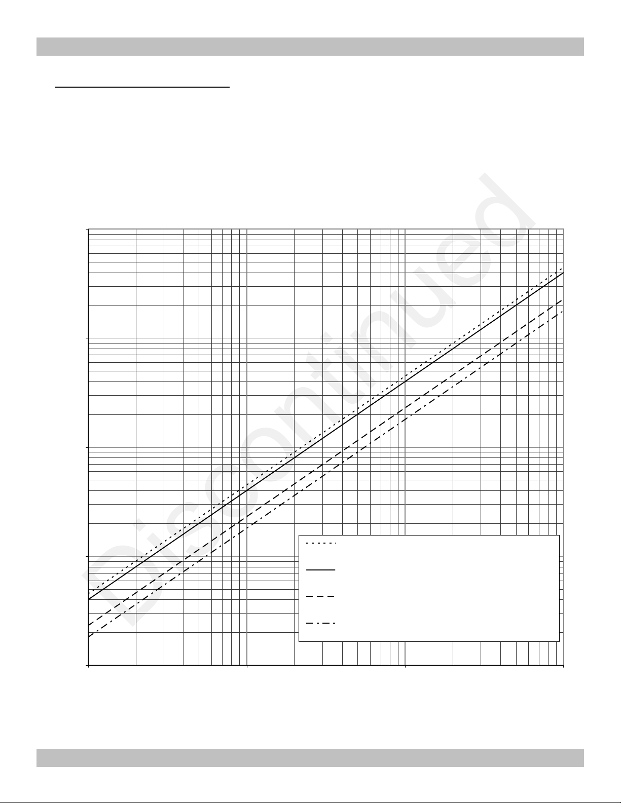
Maximum Transmission Distance
The graph below indicates typical conductor capacitance loads versus cable length for several types of
cable. For instance, 1000 feet of 7 conductor #18 gauge stran
the output of the 286-3XX Series Transmitters.
Cable Capacitance vs. Length
100
10
ded wire will put a 0.04 uF capacitive load on
1
Capacitance (uF)
0.1
0.01
1 10
2 or 4 Conductor Shielded Cable
Belden 8762 V1000 (20 GA), Belden 8723 (2 Shielded Pair)
7 Conductor Cable
National Type N W718-J (18 GA)
4 16 Gauge Wires in EMT Conduit
RG 59U Coaxial Cable
Columbia 1112 Foam
Cable Length (feet)
100
1000
286-300-
350 © 2002,
Max Machinery, Inc.
(11)

Discontinued
Maximum Transmission Distance
Maximum Transmission Distance
The graph below shows the relationship between output capacitance loading and rise and fall time for
the Model 286
the rise/fall time is 10 uS. Consequently, the absolute maximum frequency the Model 286 could transmit
would be 50 kHz (frequency = 1/time, where time include
following page for maximum frequencies possible with different flow meters.
-3XX output signal. For instance, with 0.04uF load capacitance (1000 ft. shielded cable typ.)
286-313 Output Rise and Fall Time vs. Load Capacitance
(rise and fall time measured between 10% and 90% of full output swing)
1000
(continued)
s the rise and fall times for one cycle). See
100
10
Rise and Fall Time (uS)
1
0.1
(12)
0.001
0.01
Output Capacitance Load (uF)
286-300-
0.1
350 © 2002,
1
Max Machinery, Inc.

New
Resolution
245
0.00396
0.165
5600
370
15,400
Maximum Output Frequency Range
Discontinued
K-
K-
Factors
Factors
K-factors represent the number of pulses the transmitter outputs per unit volume of fluid passing through
flow meter. This number is dependent on the flow meter and the transmitter resolution setting (switch S3).
Max Machinery indicators can be adjusted to display the desired units (ccs, lbs, gallons, quarts, etc.) by
using the K-factor.
Flow meters ar
of this K-factor is provided for each customer. The values shown below are typical. If the output resolution
setting is changed (via S3), the K-
286-3xx K-Factor Ranges (pulses/cc) with various Max flow meters*
Model
213
214
215
216
220
221
222
241
242
243
244
e multi-point calibrated at the factory. The K
factors will s
New K-factor
Combined Output
K-factor Range (pulses/cc)
Min
(@24 pulses/rev)
27.6
2.28
0.504
0.142
2.28
1.02
0.506
0.386
0.132
0.0417
0.0139
(@1000 pulses/rev)
E
Max
1150.0
95
21.0
5.9
95.0
42.5
21.1
16.1
5.50
1.74
0.579
cale proportionally:
xistingKfactor
Maximum
Rate
(liters/min)
1.8
10
40
100
3
15
38
190
540
1400
2800
-factor varies slightly with flow rate. A graph
E
xisting
Resolution
(Hz)**
Min
(@24 pulses/rev)
828 34,500
380 15,870
336 14,000
237 9,870
114 4,760
255 10,630
320 13,350
1,220 50,900
1,190 49,520
973 40,500
649 27,040
Max
(@1000 pulses/rev)
the
*typical values; may vary by up to 5% on specific flow meters.
**Maximum Count Speed of Max Machinery Indicators:
Model 120 <= 7500 Hz
Model 121 <= 20,000 Hz
If the frequency output at the application’s maximum flow rate exceeds the indicator’s c
the transmitter resolution setting (S3) will need to be adjusted to proportionally reduce the
meter/transmitter’s K
286
-300-
350 © 2002,
-Factor.
Max Machinery, Inc.
ount speed, then
(13)

Discontinued
Appendix A: Remote Mount Transmitter
286-313-500 Remote Mount Transmitter (Aluminum Housing)
286-313286-314286-314-
General
Mounting
525 Remote Mount Transmitter (Polycarbonate Ho
500 Remote Mount Transmitter with Output Level Shifter (Aluminum Housing)
525 Remote Mount Transmitter with Output Level Shifter (Polycarbonate Housing)
The 286-313located separately from the flowmeter and RVDT stator. This may be desirable when a smaller
flowmeter package is required, when the flowmeter is subjected to high ambient temperatures (ie:
environmental chamber), or for any number of other reasons. Both the remote circuit board housing and
the stator housing are fully sealed. The functionality of the remote transmitter is identical to the
standard transmitter. There are some differences in appearance and installation due to the
housing and extra connections to the remote stator cable: these are addressed in the information below.
The cylindrical aluminum stator housing mounts on the flow meter. Care should be taken when
installing and removing the stator h
damaged. Two wrench flats are provided for installing and removing. The stator housing only needs to
be tightened with enough torque to compress the O-ring and prevent unscrewing due to m
vibrations and cable forces. 10-15 ft-lbs. of torque is sufficient. DO NOT OVERTIGHTEN!
500 and 286
-313-
525 Remote Mount Transmitters allow the tra
ousing. The wire of the stator is of fine gauge and can be easily
using)
nsmitter circuitry to be
different
echanical
The sealed aluminum or polycarbonate NEMA 4 box containing the circuit board has mounting holes in
the four corners that are accessed by removing the cover
with space for a 0.265” or smaller head. The aluminum box has 0.185” holes with space for 0.300” or
smaller head. An 8
-32 socket head cap screw works well for both.
. The polycarbonate box has 0.175” dia. holes
(14)
286-300-
350 © 2002,
Max
Machinery, Inc.
D1
0
S4-2:
S5:
S3:
Output Frequency Select
D7
S4-1:
Stator Phase B
Common
S2
: Reset Microcontroller
D3-D6
: RVDT Rotor Position
S3
2-Phase
Combined
Position
Output
Output
9**
J4: Stator Cable Terminal Block
D11
Discontinued
Appendix A: Remote Mount Transmitter
Temperature Considerations
Continuo
avoided if possible. It is a good idea to locate both of these components away from hot spots such as
steam pipes, ovens, and heaters. The circuitry in the remote enclosure is rated for operation up to 80°C,
so this is the limit on the ambient air temperature at the enclosure. At the flowmeter, the metered fluid
temperature should not exceed 130° C (265° F) (stator insulation limitation) and the ambient
temperature
Outputs, Options, Indicators
See pages 6
indicators. The diagram below points out the location of the f
Testpoints
us exposure of the stator housing and the circuitry to high ambient temperatures should be
should not exceed 105° C (220° F) (PVC cable jacket limitation).
-8 of the manual for detailed explanations of the transmitter’s outputs, options, and
Wire
Colors Denoted on PCB
“DRN” indicates the Drain wire
Connected to cable shielding
S1-2: Filter
S1-1:
Ground
eatures on the printed circuit board.
: Output/Phase A (Terminal 4 & 5
Status) (High = Green, Low = Red)
: Direction/Phase B (Terminal 6
Status) (High = Green, Low = Red)
Terminal Block
1. Case (Green)
2. Common (Black)
3. Power 5-30VDC (Red)
4. Combined Output (White)
5. Phase A Out (Orange)
6. Phase B Out or Direction (Blue)
Stator Phase A
: Microcontroller Memory
Status (On = Fail)
Cycles per Revolution
0
0 (Calibrate)
1
2
3
4
5
6
7
8
* Not Specified, Usually same as S3=8
12
25
50
100
150
250
300
500
0 (Calibrate)
24
50
100
200
300
500
600
1000
And Calibration Enable
Select Meter Type
Output Select (2- Phase
or Combined Output)
Indication (4 LED’s)
D9
: Calibration Active
D8
: Flow too low to calibrate
Calibrate Stator Offsets
(and Angle). Need S3 in
position 0 to start Calibration.
286-300-
350 © 2002,
Max Machinery, Inc.
(15)

Discontinued
Appendix B: Output Level Shifter Option
286-
314:
Transmitter with Amphenol Connector, Level Shifter Option
286-
324:
Transmitter, Weather
286-314286-314-
General
Outp
Supply Voltage........................................................................
Supply Current....................................
Output
500:
Remote Transmitter (Aluminum Housing), Level Shift
525: Remote Transmitter (Polycarbonate Housing), Level Shifter Option
Both the standard and remote transmitter circuit boards have the capability for additional circuitry that
gives output voltage levels equivalent to the power supply voltage. For example, if the transmitter is
powered with +12 Volts the output will be a 12V square wave. The circuit board used in the level
shifter version is identical to the standard circuit board, with the exception of some additional
compon
specifications, some different than those on pg. 3 due to the level shifter, are listed below. All other
specifications from pg. 3 not reprinted here remain unchanged.
ents (R29,R30, and U9) and some that are absent (R23, R24, and D1). The output
ut Level Shifter Specifications
(12.0V Supply) ........................................................................................Hi Lo
No Load..............................................................................................
2.5k Load to Common........................................................................ 11.0 V 0.1 V
2.5k Load to +12 Volts.......................................................................
Short Circuit C
Output Impedance...............................................................................100
Rise Time .................................................................................
Fall Time..................................................................................
Maximum Frequency .........................................................................
Minimum Frequency..............................................................................
urrent
5
.......................................................................
-Tight, Explosion Proof, Level Shifter Option
38mA Typical, 32-
er Option
4.5 VDC to 30 VDC
43 mA Range (+ Load)
120 mA
0.8 uS (90%)
1.0 uS (90%)
60 kHz
12.0 V 0.1 V
12.0 V 1.0 V
0 Hz
5
Continuous Short Ci
(16)
rcuit is not recommended. The output current should not exceed 30 mA per output.
286-300-
350 © 2002,
Max Machinery, Inc.
 Loading...