


INSTRUCTION MANUAL
Discontinued
276-5XX SERIES 4-20MA TRANSMITTERS
276-515 4 Phase (210 Meters) Amphenol
276-525 4 Phase (210 Meters) Weather-Tight, Explosion proof (UL, CSA)
276-517 7 Phase (220/240 Meters) Amphenol
276-527 7 Phase (220/240 Meters) Weather-Tight, Explosion proof (UL, CSA)
TABLE OF CONTENTS
General Description . . . . . . . . . . . . . . . . . . . . . . . . . . . . . . . . . . .Pg 2
Specifications . . . . . . . . . . . . . . . . . . . . . . . . . . . . . . . . . . . . . . . .Pg 3
Installation:
Mounting / Dimensions . . . . . . . . . . . . . . . . . . . . . . . . . . . . .Pg 4
Moisture Protection / Temperature Considerations . . . . . . . . .Pg 5
Grounding / Typical Wiring Schematics . . . . . . . . . . . . . . . . .Pg 6
User Options & Adjustments:
Zero and Span Adjustments . . . . . . . . . . . . . . . . . . . . . . . . . .Pg 7
Damping / Over Range Indication . . . . . . . . . . . . . . . . . . . . .Pg 8
PCA Drawings . . . . . . . . . . . . . . . . . . . . . . . . . . . . . . . . . . . .Pg 9
Ripple Adjustment (276-515 and 276-525) . . . . . . . . . . . . . .Pg 10
General Considerations:
Response Rate, Accuracy & Noise . . . . . . . . . . . . . . . . . . . . .Pg 11
Schematics:
D276-515-200
D276-517-200
276-515-350 © 2006, Max Machinery, Inc.
Max Machinery, Inc. reserves the right to make changes to the product in this Instruction
Manual to improve performance, reliability, or manufacturability. Consequently, contact
MMI for the latest available specifications and performance data.
Although every effort has been made to ensure accuracy of the information contained in
this Instruction Manual, MMI assumes no responsibility for inadvertent errors.

( 2 ) 276-515-350 © 2006 Max Machinery, Inc.
GENERAL DESCRIPTION
Discontinued
General Description: The Max 276 Series Transmitters are 4-20mA output devices available
in two versions: One for the Max 210 Series Flowmeters and one for the 220/240 Series. Each
is available with either amphenol connectors or in a weather-tight, explosion proof version for
use with conduit.
The transmitter uses a stator coil to sense the motion of a rotating magnet contained within the
flow meter. This generates a two phase AC signal with a voltage proportional to the flow rate.
The Transmitter electronics convert this signal to a DC voltage and then into the 4-20mA flow
proportional output.
The 276 transmitter is a two wire, loop powered device that uses about 3.5mA of the 4-20mA
which normally flows through the Transmitter. It will operate correctly with a minimum
voltage of 11.5 V and up to a maximum of 35 V.
On board controls include a Zero adjustment, Range and Span settings, and a three pole
damping filter.An LED indicates over range conditions which can cause a loss of accuracy.
When used with the Max 210 Series Flowmeters, the 276 Transmitter can be adjusted to
electronically demodulate the nonlinear rotational rate of the crankshaft. This effect is inherent
in piston type flow meters.
The Max 276 Series Transmitters generally provide faster response to flow rate changes than
pulse type Transmitters. This is particularly true with the 210 series meters at low flow rates.

276-515-350 © 2006 Max Machinery, Inc. ( 3 )
SPECIFICATIONS
Discontinued
Specifications:
Range (Flowmeter RPM)
Accuracy
Temperature Range (See Temperature Considerations)
For a 4-20mA Output
276-515 and 276-525 . . . . . . . . . . . . . . . . . . . . . . . 21 RPM Minimum
3600 RPM Maximum
276-517 and 276-527 . . . . . . . . . . . . . . . . . . . . . . . .18 RPM Minimum
3600 RPM Maximum
Linearity (Input RPM vs Output Voltage)
Typical . . . . . . . . . . . . . . . . . . . . . . . . . . . . . .± 0.05% or ± 0.01mA
(whichever is larger)
Maximum . . . . . . . . . . . . . . . . . . . . . . . . . . . . . . .± 0.1% or ± 0.01mA
(whichever is larger)
Zero Stability . . . . . . . . . . . . . . . . . . . . . . . . . . . . . . . . . . . . .± 0.01mA
Electronics:
Operating . . . . . . . . . . . . . . . . . . . . . . . . . . . . . . . . . -10°C to 65°C
Storage . . . . . . . . . . . . . . . . . . . . . . . . . . . . . . . . . . -40°C to 70°C
Stator . . . . . . . . . . . . . . . . . . . . . . . . . . . . . . . . . . . . . -40°C to 130°C
Temperature Coefficients
Flowmeter Magnet . . . . . . . . . . . . . . . . . . . . . . . . . ± 0.5% per 100°C
Transmitter
Span . . . . . . . . . . . . . . . . . . . . . . . . . . . . . . . . . . ± 0.2% per 100°C
Zero . . . . . . . . . . . . . . . . . . . . . . . . . . . . . . . . + 0.01mA per 100°C
Supply Voltage
Maximum at 25mA . . . . . . . . . . . . . . . . . . . . . . . . 35V (Continuously)
50V (5 Sec or less)
Minimum at 4mA . . . . . . . . . . . . . . . . . . . . . . . . . . . . . . . . 10.5 Volts
at 20mA . . . . . . . . . . . . . . . . . . . . . . . . . . . . . . . . . . . . . . . . 11.5 Volts

( 4 ) 276-515-350 © 2006 Max Machinery, Inc.
INSTALLATION
—Mounting & Dimensions
Discontinued
Mounting: The 276 Transmitter screws on and off of the Flowmeter. Because of the random
location of the starting point of the threads, one Transmitter will probably not line up with the
“in” and “out” ports of the Flowmeter like another will. The electrical outlet of the Transmitter
can be rotated clockwise or counter clockwise one turn by loosening the clamping screw at
the base of the Transmitter housing [shown below].
Two flats are provided for screwing the Transmitter on to the Flowmeter. Care should be
taken when slipping the Transmitter on and off. The stator wire can be easily damaged.

276-515-350 © 2006 Max Machinery, Inc. ( 5 )
INSTALLATION
—Moisture Protection & Temperature Considerations
Moisture Protection: The weather-tight version of the Transmitter has it’s electronic circuitry
enclosed in a liquid and vapor tight enclosure. All joints are sealed by welding or by “O”-rings.
If this sealed condition is to be maintained, the conduit connection to the enclosure should be
made liquid and vapor tight by using pipe dope or a potting fitting. If a Transmitter is located
outside and this precaution is not taken, moisture may form inside the housing. This will cause
the circuitry to give an inaccurate output or possibly no output at all. In the long run it will
cause corrosion and failure. The amphenol connector 276 Transmitter models offer moderate
protection from moisture and dust, but are not totally sealed.
Temperature Considerations: High ambient temperatures (120°F/50°C) should be avoided if
possible. It is a good idea to locate the Transmitter away from hot spots such as steam pipes,
ovens and heaters. The electronics of the 276 Series Transmitters are rated for operation up to
65°C or 150°F. Because some
heat travels from the
Flowmeter to the Transmitter
electrical enclosure, the
temperature of the electronics
within is a function of both the
Ambient and the Flowmeter
temperature. The figure [top,
right] shows the relationship
between the maximum ambient
Transmitter temperature and the
fluid temperature through the
Flowmeter.
The stator of the 276
Transmitters is insulated with an
epoxy that is rated to 130°C.
This limits the maximum
Flowmeter fluid temperature to
about 130°C.
The output of the 276
Transmitter will be affected by
changes in the temperature of
the Flowmeter. This is because
the magnet that generates the
voltage in the stator is affected
slightly by temperature. The
figure [bottom, right] shows
typical percentages of error.
Discontinued

( 6 ) 276-515-350 © 2006 Max Machinery, Inc.
INSTALLATION
—Grounding / Typical Wiring Schematics
Grounding Jumpers: Two options are available for connecting the minus output to the case
ground. These are shown schematically, below, in a typical wiring diagram.
As supplied by the factory, a jumper is installed in the “filter” position, which capacitively
couples minus and ground. This arrangement reduces possible electrical noise problems.
The “ground” jumper would connect minus and case ground directly together, and is supplied
in an open condition. Some readout instruments do not have zero volts at the minus terminal,
and a direct ground connection would not be advisable.
In a typical installation, the Transmitter case is grounded through the plumbing. An alternative
is to make the ground connection at the “case” terminal on the printed circuit board.
Discontinued

276-515-350 © 2006 Max Machinery, Inc. ( 7 )
USER OPTIONS & ADJUSTMENTS
—Zero & Span Adjustments
Discontinued
Zero Adjustment: R52 (276-515/276-525) R64 (276-517/276-527) Adjust the output current
to 4.000mA with zero flow through the Flowmeter.
Span Adjustment: S1 Coarse Range and R35 or R47 Fine Span Adjustment. Table I lists the
approximate volumetric displacements of flow meters that can be used with the 276
transmitters. Use this table to calculate the RPM of the flow meter at maximum flow.
METER MAXIMUM FLOW AND DISPLACEMENT
FLOWMETER MAXIMUM FLOW DISPLACEMENT PER REVOLUTION
CC/MIN GAL/MIN CC GALLONS
213 1,800 0.48 0.870 .00023
214 10,000 2.64 10.5 .00285
215 40,000 10.6 47.6 .0128
216 100,000 26.4 169.5 .0446
220 10,000 2.64 9.12 .0024
221 55,000 14.5 23.5 .0062
222 75,000 19.8 47.4 .0125
241 189,000 50.0 62.1 .0164
251 189,000 50.0 62.1 .0164
242 540,000 143.0 182.0 .0480
243 1,400,000 370.0 574.0 .152
244 3,500,000 925.0 1700.0 .456
TABLE I.
245 8,000,000 2114.0 6060.0 1.60
(FOR EXAMPLE: THE 213 MAX RPM IS: 1800 CC/MIN ÷ 0.870 CC/REV = 2069 RPM.)
Table II lists the RPM range of each Range Switch setting for both 276 transmitters. Use this
table to estimate the correct range position.
TABLE II.
RPM RANGE VS SWITCH POSITION (RPM AT 20mA OUT)
2 7 6 - 5 X 5 2 7 6 - 5 X 7
SWITCH MAX MIN MAX MIN
POSITION GAIN GAIN GAIN GAIN
1 1294 3620 1290 3612
2 568 1589 549 1537
3 249 697 233.6 654
4 109 306 99.4 278.3
5 48 134 42.3 118.4
6 21 59 18 50.4

( 8 ) 276-515-350 © 2006 Max Machinery, Inc.
USER OPTIONS & ADJUSTMENTS
—Damping & Output Over Range LED
Damping: R37/38/39 or R49/50/51. The 276 Transmitter has a damping network which is used
to average out meaningless variations in the output current which can result from system layout,
pump noise, or Flowmeter design. To adjust the damping, set the flow rate to the lowest flow
that will typically be used. Increase the setting of the three damping potentiometers equally until
the indicated flow rate shows the desired stability. Increasing the damping will also slow the
response to actual flow rate changes, so use the minimum damping necessary.
Output Over Range LED: This LED will start to blink if the Transmitter output amplifier begins
to saturate (clip). This happens when the flow rate or gain is too high. Clipping will cause the
output current to be less than it should be and not a true indication of flow rate. The figure below
shows what happens as the flow rate is increased to the point at which the output is saturated.
The flow rate in a system may have as much as 50% to 100% ripple. This may be caused by the
pump, by air in the line, or a slightly sticky Flowmeter. The maximum output current of the 276
Transmitter must be kept low enough so that the output is not saturated. This may mean that the
average full scale output current will have to be less than 20mA to avoid clipping the peaks in
the output signal, as indicated in the figure below.
Discontinued

276-515-350 © 2006 Max Machinery, Inc. ( 9 )
USER OPTIONS & ADJUSTMENTS
—PCA Drawings
276-515/525
276-517/527
CASE
+ OUTPUT
- OUTPUT
R52 ZERO
L2 RIPPLE LED
R33
RIPPLE ADJUSTMENT
SENSITIVITY
STATOR ADJUSTMENT
SCREW
GROUNDING JUMPERS:
(SUPPLIED WITH
JUMPER IN “FILTER”
POSITION.)
R37,38,39 DAMPING
L1 OVERRANGE LED
R35 OUTPUT SPAN
S1 OUTPUT RANGE
(2.1:1 STEPS)
CASE
+ OUTPUT
- OUTPUT
R64 ZERO
GROUNDING JUMPERS:
(SUPPLIED WITH
JUMPER IN “FILTER”
POSITION.)
R49,50,51 DAMPING
L1 OVERRANGE LED
R47 OUTPUT SPAN
S1 OUTPUT RANGE
(2.1:1 STEPS)
Discontinued

( 10 ) 276-515-350 © 2006 Max Machinery, Inc.
USERS OPTIONS & ADJUSTMENTS
—Ripple Adjustment
Ripple Adjustment: (276-515 and 276-525 Transmitters Only)
This adjustment will have to be made if the Transmitter is unscrewed from the Flowmeter.
The 276-515 and the 276-525 Transmitters are made to compensate for the non uniform rotational
rate of the 210 series piston meters, which can cause as much as 50% ripple at the Transmitter
output. To take advantage of this feature, the stator of the 276 Transmitter must be positioned
correctly for each meter it is mated to.
The Flowmeter must have a flow through
it for this adjustment to be made. It is
advisable to adjust the ripple at the lower
end of the flow range; although if the
flow rate is less than 5% of the
Flowmeter’s full scale capability, you
may have problems with this procedure.
Increase the Sensitivity Adjustment (R33)
clockwise just until the Ripple LED (L2)
next to it starts to turn on. Then turn the
Stator Adjustment Screw in a direction that decreases the brightness or turns off the Ripple LED.
Once again increase the Sensitivity Potentiometer until the LED just comes on and again turn the
stator adjustment in a direction that minimizes the LED brightness. Repeat this process until any
further change in the position of the stator screw causes the LED brightness to increase rather
than decrease.
Shown below is the effect of the stator position on output ripple. There are four best and four
worst positions for the stator per revolution. This means that it will take a maximum of 45° on the
Stator Adjustment Screw to find the best location.
Discontinued
— ATTENTION —
The Transmitter pickup coil is phased to
the Flowmeter. If the two are unscrewed
for any reason, realignment will be
necessary. See Transmitter Manual.
LOOSEN TO ROTATE TRANSMITTER
(1 TURN MAXIMUM)
DO NOT UNSCREW HERE
OUTPUT RIPPLE VS STATOR POSITION
WORST STATOR
POSITION
50% Ripple 10% Ripple
1 2 3 4 5
BEST STATOR
POSITION
276-515-350 © 2006 Max Machinery, Inc. ( 11 )
GENERAL CONSIDERATIONS
—Response Rate, Accuracy & Noise
NOISE
ACCURACY
Discontinued
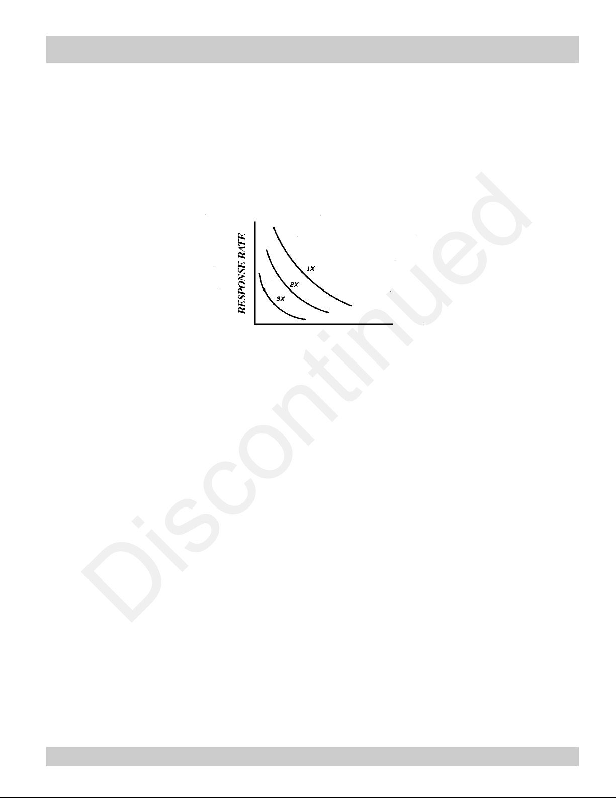
Response Rate, Accuracy & Noise: There is always a trade off in a metering system between
response rate, accuracy and noise. The three are related such that their product equals a
constant. If any one of them is made smaller, the others can be made larger.
In most metering systems, response rate and accuracy are desirable characteristics. To
maximize one or both of these parameters, noise should be reduced to a minimum. Once noise
has been minimized, there is a trade off between accuracy and response rate.
FAST
SLOW
LEAST MOST
Response Rate: When discussing response rate there are three facets to consider. They are: the
response of the flow to a change in the system set point, the correction of the flow to an error
induced in it, and the response of the flow rate display to a change in flow rates. These
responses are all purposely slowed down by filtering or damping so the system only reacts to
meaningful flow changes and not to such things as pump pulsations or Flowmeter ripple.
More damping means slower response.
Accuracy: There are three topics to consider when looking at accuracy. The first being the
display; which can typically have anywhere from two digits (1 to 99) to 4-1/2 digits (19,999)
of information. This equals a resolution of 1% to a maximum of 0.005%, respectively. The
display steadiness is also directly related to it’s accuracy. For instance, a display that jitters
from 95 to 105 in a meaningless way is not accurate to one part in 100 (1%) but only to about
10 parts in 100 (10%).
The basic accuracy of the Flowmeter is a prime consideration. Typically, the accuracy of a
positive displacement meter is not as good for a fraction of its cycle as it is for one or more
complete cycles. If a system is dampened so that the response rate is longer than the period of
one revolution of the meter, the accuracy of the display is increased. The accuracy of the
system can never be better than that of the Flowmeter.

( 12 ) 276-515-350 © 2006 Max Machinery, Inc.
GENERAL CONSIDERATIONS
—Response Rate, Accuracy & Noise (cont.)
Discontinued
Noise: Noise can be defined as any change in either the fluid flow or the electrical system that
is not a meaningful change in the flow rate. For instance, the ripple induced in the flow by a
gear or piston pump is noise. The system will typically have to be dampened so that its’
response time is longer than the tooth to tooth period of the pump. Piston pumps with fewer
than three pistons create a particularly large amount of
bothersome ripple and result in a system that is very
slow to respond.
All positive displacement Flowmeters add noise to a
Flowmetering system. The noise is typically of two
origins. As the elements of the meter rotate, they
require varying amounts of pressure to move (As
shown in illustration, right).
This induces pressure fluctuations between the pump
(or control valve) and the Flowmeter. If there is any air trapped in the line, the fluid flow will
vary as the air compresses and expands. This will be sensed as a changing flow by the
Flowmeter and the output will contain unwanted ripple or noise. Plumbing in a flow system
should be sized and laid out to avoid air being trapped between the Flowmeter and the flow
controlling device (a pump or valve).
PRESSURE DROP VS TIME
(210 SERIES PISTON METER)
TIME
The second type of noise that must be considered is
a result of Flowmeter geometry and design. Because
of features such as an oval gear, or a
piston/crankshaft configuration, or due to
manufacturing tolerances, the rotation of the
metering elements is not completely uniform. For
example, the 210 series meters utilize four pistons
connected to a crankshaft. The varying rotational
speed of the crankshaft is shown in the figure to the
right.
To obtain the smoothest output signal, the Transmitter (276-515 or 276-525) for these meters
can be adjusted to minimize this characteristic. Additionally, some amount of damping is
usually necessary at the indicator.
The electronic converter of any meter will add its share of noise. For instance, DC
Transmitters produce some ripple in their output due to the sinusoidal nature of the induced
voltage in the armature coils.
ROTATIONAL SPEED
(OF 210 CRANKSHAFT)
TIME
 Loading...