

Page 1
Evolution UC16
USB MIDI Controller with 16 rotary programmable
controllers, 25 Memory Banks and USB
WWW.EVOLUTION.CO.UK
EVOLUTION UC16 USB MIDI CONTROLLER MANUAL
Page 2
1. POWER SUPPLY
There are two methods of powering the UC16.
AC Power
You can also use an AC adapter (not included) with the following specification: 9-12V DC
output, 250-300mA, centre positive.
Connect to the USB port on your computer. The UC16 is powered from USB.
Note: Do not leave the adapter plugged in for long periods of time if the unit is not in use.
Only use one method at one time
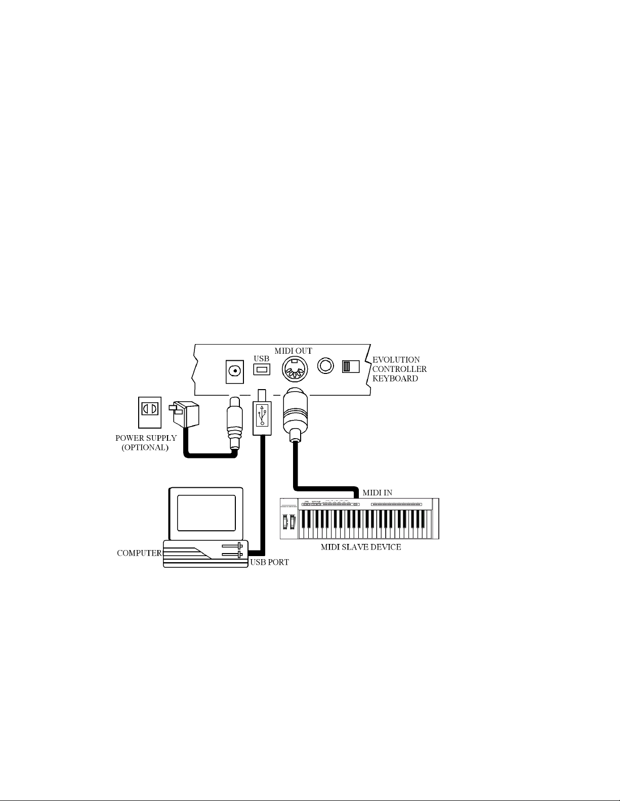
2. Preparation
Connect the unit with other MIDI equipment you may have:
The UC16 will act as a MIDI interface for any other MIDI equipment you may have. Note
however, that it will only act as a MIDI THRU device. It will receive data from the USB port of
the computer and pass this data on to the connected device. It can not transmit data from a
connected device to the computer.
Turn on the POWER switch.
Turn all other equipment on.
Page 3

3. Assignable Rotary controllers
There are 16 assignable controllers selected by the CONTROL SELECT & CONTROL ASSIGN
functions.
‘
Assignable Controllers’
The basic operation is:Select the controller by moving it. Alternatively, you can press the CONTROL SELECT button
and then type in the number using the keypad or ‘+’, ‘-‘ buttons. Press the CONTROL ASSIGN
button and enter the new number using the keypad.
To change one of the assignable controllers, the UC16 uses the following method:
Press the CONTROL SELECT button and release. Alternatively simply move the rotary control.
The number of the presently selected MIDI controller will flash.
Select a controller by moving any one of the assignable controllers, the numeric keypad or the
+/- keys.
The LED display will show the new MIDI controller number assignment.
Repeat this process to see the
moving the relevant controller or by typing a new number.
If no keys are pressed or any of the assignable controllers moved, the LED display stops
flashing after 3 seconds and returns to normal operation.
Press the CONTROL ASSIGN button & release.
The number entered at this point will be assigned to the last selected controller.
The numeric entry uses the standard data entry system. (see section on Entering Numbers)
If a complete number is entered the display stops flashing and the new assignment is stored.
If the Inc/Dec keys are used, the revised value is shown on the LED display and the flashing
time-out is reset.
Once a controller has been assigned the current knob position should be sent out.
This ensures that when the controller if first moved it does not trigger a large jump from it’s
previous setting.
refers to any of the 16 assignable Knobs.
controller number assignment
(0-132) for any Knob (1-16), by
During the data entry stage while the LED display is flashing, the Knobs,
do not function.
Page 4

4. Entering Numbers
When any number is entered it adheres to the following rules:Increment/Decrement Keys
Initially the LED display starts flashing.
The value displayed can be incremented/decremented using the +/- keys.
Pressing both + & - should call up the default value for that parameter.
The LED display shows the new value.
The new value is sent out except for the CONTROL ASSIGN which sends data when the display
stops flashing)
When the display stops flashing the keyboard returns to normal operation.
Numeric Keys
Initially the LED display starts flashing.
A numeric value can be typed in using the numbers 0-9.
As each key is pressed the display continues to flash, the time-out value is reset.
When a
Alternatively, if no key is pressed and the display stops flashing the number on the display is
The update routine is triggered, so that the new value is sent out.
When the display stops flashing the keyboard returns to normal operation.
* The following table shows how many keys are required to enter a complete number:-
complete number
selected.
selected.
* has been entered the display stops flashing and the value is
1 key 2 keys 3 keys
Channel 2-9 01, 10-16
Memory 0-9
Control Select 2-9 01,10-14
Control Assign 14-99 000-013, 100-132
5. Snap Shot
When both SNAP SHOT keys are pressed the UC-16 sends out the settings for all of the
Assignable Controllers. The settings will be sent out on whichever channel each rotary dial is
assigned to (see channel assignment later). This feature lets you record the settings of the Knobs
into your sequencer. It is handy for setting up parameters in a song. Set the UC16 to all
parameter levels you desire, engage record mode on your sequencer and press the SNAP SHOT
buttons.
Page 5

6. Memory banks and Presets
There are 25 memory banks in total. Memory banks 1-4 are accessible using the Preset buttons
1-4 respectively. This allows you to stor e settings you use a lot and makes for easy access to
them. By default the 4 presets are:
1. Propellerhead’s Reason mixer
2. Steinberg’s Halion sampler
3. Native Instruments FM7
4. General GM/GS/XG preset.
The rest of the memory banks are accessible by pressing the RECALL button, then using either
the +/- buttons or the numeric keys to type in the number of the memory bank you want (1-25). By
default the remaining presets are:
5. Native Instruments B4
6. Native Instruments Pro-52
7. Steinberg Model-E
8. Waldorf Attack
9. Waldorf PPG wave 2V
10.Propellerhead's Rebirth Master
11.Propellerhead's Rebirth Rhythm section
12.Reason Subtractor
13.Reason Dr. Rex
14.Reason NN-19
15.AAS Lounge Lizard
16. Native Instruments Traktor DJ
17.cc numbers 40 – 55.
18.cc numbers 75 – 90
19.cc numbers 102 – 117
20.Volume (cc7) on channels 1 – 16
21.Pan (cc7) on channels 1 – 16
Bank numbers 22 – 25 have the same default as bank number 4.
For a fully detailed list of the memory bank presets please look at the UC16 Memory bank
definitions document bundled with your UC16, or available to download from our website.
It is also possible to store your own presets.
To save the current settings for all 16 controllers press the MEMORY buttons (CHANNEL
ASSIGN and RECALL), then type in the number of the memory bank you want (1-25).
Alternatively, you can use the ‘+’ and ‘-‘ buttons.
Each memory bank will store the current Program number and channel transmit number for all of
the 16 controllers.
If you make a mess of things, don’t worry – you can always get the factory presets back by
holding down the ‘+’ and ‘-‘ keys on power up.
Page 6

7. Setting the MIDI Transmit Channel
The MIDI channel can be set for each rotary contro ller individually. To do this press the
CHANNEL ASSIGN button. The c hannel the currently selected rotary dial is assigned to will flash
on the LED display. For example, if the last selected dial is currently assigned to channel 1, the
LED display will flash ‘c 1’. Increment or decrement the channel using the numeric keypad, or the
‘+’ and ‘-‘ buttons.
8. MIDI OUT FROM USB
The MIDI output connector is normally used to send MIDI data from the UC16. If the UC16 is
connected to a computer using USB the MIDI Out can also be used to send data received from
USB.
Pressing both MIDI OUT FROM USB buttons flashes the current setting on the LCD display.
The +/- keys can be used to alter the current setting. + selects YES, - selects NO.
Pressing both + and - calls up the default setting which is NO.
When ‘NO’ is selected the MIDI Out sends the data from the UC16.
When YES is selected the MIDI Out sends the MIDI data received from USB.
The status of MIDI OUT FROM USB will be saved in non-volatile memory and restored when the
UC16 is switched on again. The factory default is set to NO.
9. SPECIFICATIONS
1. Control
POWER ON/OFF, Numeric Keys (0-9), PRESET BUTTONS 1-4, + AND - KEYS)
3. Rotary Controls: 16 rotary controls with assignable controller and channel values
5. Memory storage - non volatile, 25 banks, 4 fast presets
6. Display
7. Jack
8. Dimension
9. Weight
Note: Specifications are subject to change without prior notice.
: Switches: (CHANNEL ASSIGN, MEMORY, CONTROL ASSIGN, CONTROL SELECT,
: 3 digit LED
: DC IN (DC 9V), MIDI OUT, USB
: 29.6cmX12.5cmX4.8cm
: 0.75Kg
Page 7

APPENDIX A
MIDI IMPLEMENTATION CHART
Function Transmitted Received Remarks
Basic :Default Channel: Changed 1-16 1-16
:Default Mode :Messages :Altered --------- X *********
Note Number:True Voice 0-127 *********
Velocity: Note ON : Note OFF X X
After :Key’s Touch :Ch’s X •
Pitch Bend X
0,32 1 Control 6 Change 7
64
1-31 33-95 102-121 • • • Mod Wheel Assign
Program Change:True Number 0-127 *********
System Exclusive X
:Song Position Com mon:Song Select
:Tune
System :Clock E xclusive:Commands X X
Aux :Local ON/OFF Messages:All Notes
OFF :Active Sense :Reset
Notes: • : Can be set to 0 or X
For support email support@evolution.co.uk
Latest drivers and information at www.evolution.co.uk
Join the Evolution User’s group at Yahoo groups, www.yahoogroups.com/group/evolution-users
or e-mail to this address: evolution-users-subscribe@yahoogroups.com
• • • 0 0 Bank select Modulation Data
Entry Volume Hold 1
X X X
X X 0 X
Page 8

APPENDIX B
STANDARD CONTROLLER NUMBERS
No. Controller
00 Bank Select
01 Modulation
02 Breath Control
03 Controller 3
04 Foot Control
05 Porta Time
06 Data Entry
07 Channel Volume
08 Balance
09 Controller 9
10 Pan
11 Expression
12 Effects Controller 1
13 Effects Controller 2
14 Controller 14
15 Controller 15
16 Gen Purpose 1
17 Gen Purpose 2
18 Gen Purpose 3
19 Gen Purpose 4
20 Controller 20
21 Controller 21
22 Controller 22
23 Controller 23
24 Controller 24
25 Controller 25
26 Controller 26
27 Controller 27
28 Controller 28
29 Controller 29
30 Controller 30
31 Controller 31
32 Bank Select LSB
33 Modulation LSB
34 Breath Control LSB
35 Controller 35
36 Foot Control LSB
37 Porta Time LSB
38 Data Entry LSB
39 Channel Volume LSB
40 Balance LSB
41 Controller 41
42 Pan LSB
No. Controller
43 Expression LSB
44 Controller 44
45 Controller 45
46 Controller 46
47 Controller 47
48 Gen Purpose 1 LSB
49 Gen Purpose 2 LSB
50 Gen Purpose 3 LSB
51 Gen Purpose 4 LSB
52 Controller 52
53 Controller 53
54 Controller 54
55 Controller 55
56 Controller 56
57 Controller 57
58 Controller 58
59 Controller 59
60 Controller 60
61 Controller 61
62 Controller 62
63 Controller 63
64 Sustain Pedal
65 Portamento
66 Sostenuto
67 Soft Pedal
68 Legato Pedal
69 Hold 2
70 Sound Variation
71 Resonance
72 Release Time
73 Attack Time
74 Cutoff Frequency
75 Controller 75
76 Controller 76
77 Controller 77
78 Controller 78
79 Controller 79
80 Gen Purpose 5
81 Gen Purpose 6
82 Gen Purpose 7
83 Gen Purpose 8
84 Portamento Control
85 Controller 85
No. Controller
86 Controller 86
87 Controller 87
88 Controller 88
89 Controller 89
90 Controller 90
91 Reverb Depth
92 Tremelo Depth
93 Chorus Depth
94 Celeste (De-tune)
95 Phaser Depth
96 Data Increment
97 Data Decrement
98 Non-Reg Param LSB
99 Non-Reg Param MSB
100 Reg Param LSB
101 Reg Param MSB
102 Controller 102
103 Controller 103
104 Controller 104
105 Controller 105
106 Controller 106
107 Controller 107
108 Controller 108
109 Controller 109
110 Controller 110
111 Controller 111
112 Controller 112
113 Controller 113
114 Controller 114
115 Controller 115
116 Controller 116
117 Controller 117
118 Controller 118
119 Controller 119
Channel Mode Messages
120 All Sound off
121 Reset all Controllers
122 Local Control
123 All Notes Off
124 Omni Off
125 Omni On
126 Mono On (Poly Off)
127 Poly On (Mono Off)
 Loading...