

Page 1

English . . . . . . . . . . . . . . . . . . . . . . . . . . . . . . . . . . . . . . . . . . . . . . . . . . . . . . . . . . . . . . . . . . . . . . . . .2
Introduction . . . . . . . . . . . . . . . . . . . . . . . . . . . . . . . . . . . . . . . . . . . . . . . . . . . . . . . . . . . . . . . . . . . . . . . . . . . . . . . . . . . . . . . . . . . . . . . . . . . . . . . . .2
What’s in the Box . . . . . . . . . . . . . . . . . . . . . . . . . . . . . . . . . . . . . . . . . . . . . . . . . . . . . . . . . . . . . . . . . . . . . . . . . . . . . . . . . . . . . . . . . . . . . . . . . . . .2
About Octane . . . . . . . . . . . . . . . . . . . . . . . . . . . . . . . . . . . . . . . . . . . . . . . . . . . . . . . . . . . . . . . . . . . . . . . . . . . . . . . . . . . . . . . . . . . . . . . . . . . . . . .2
Features . . . . . . . . . . . . . . . . . . . . . . . . . . . . . . . . . . . . . . . . . . . . . . . . . . . . . . . . . . . . . . . . . . . . . . . . . . . . . . . . . . . . . . . . . . . . . . . . . . . . . . . . . . . .2
Controls and Connectors . . . . . . . . . . . . . . . . . . . . . . . . . . . . . . . . . . . . . . . . . . . . . . . . . . . . . . . . . . . . . . . . . . . . . . . . . . . . . . . . . . . . . . . . . . . . . .3
Front Panel Descriptions . . . . . . . . . . . . . . . . . . . . . . . . . . . . . . . . . . . . . . . . . . . . . . . . . . . . . . . . . . . . . . . . . . . . . . . . . . . . . . . . . . . . . . . . . .3
Rear Panel Descriptions . . . . . . . . . . . . . . . . . . . . . . . . . . . . . . . . . . . . . . . . . . . . . . . . . . . . . . . . . . . . . . . . . . . . . . . . . . . . . . . . . . . . . . . . . .5
Connections . . . . . . . . . . . . . . . . . . . . . . . . . . . . . . . . . . . . . . . . . . . . . . . . . . . . . . . . . . . . . . . . . . . . . . . . . . . . . . . . . . . . . . . . . . . . . . . . . . . . . . . . .5
Using the Octane . . . . . . . . . . . . . . . . . . . . . . . . . . . . . . . . . . . . . . . . . . . . . . . . . . . . . . . . . . . . . . . . . . . . . . . . . . . . . . . . . . . . . . . . . . . . . . . . . . . .6
Troubleshooting . . . . . . . . . . . . . . . . . . . . . . . . . . . . . . . . . . . . . . . . . . . . . . . . . . . . . . . . . . . . . . . . . . . . . . . . . . . . . . . . . . . . . . . . . . . . . . . . . . . . . .8
Specifications . . . . . . . . . . . . . . . . . . . . . . . . . . . . . . . . . . . . . . . . . . . . . . . . . . . . . . . . . . . . . . . . . . . . . . . . . . . . . . . . . . . . . . . . . . . . . . . . . . . . . . . .9
Warranty . . . . . . . . . . . . . . . . . . . . . . . . . . . . . . . . . . . . . . . . . . . . . . . . . . . . . . . . . . . . . . . . . . . . . . . . . . . . . . . . . . . . . . . . . . . . . . . . . . . . . . . . . . .10
Contact M-Audio . . . . . . . . . . . . . . . . . . . . . . . . . . . . . . . . . . . . . . . . . . . . . . . . . . . . . . . . . . . . . . . . . . . . . . . . . . . . . . . . . . . . . . . . . . . . . . . . . . . .10
Français - . . . . . . . . . . . . . . . . . . . . . . . . . . . . . . . . . . . . . . . . . . . . . . . . . . . . . . . . . . . . . . . . . . . . . .11
Introduction . . . . . . . . . . . . . . . . . . . . . . . . . . . . . . . . . . . . . . . . . . . . . . . . . . . . . . . . . . . . . . . . . . . . . . . . . . . . . . . . . . . . . . . . . . . . . . . . . . . . . . . . .11
Contenu de la boîte . . . . . . . . . . . . . . . . . . . . . . . . . . . . . . . . . . . . . . . . . . . . . . . . . . . . . . . . . . . . . . . . . . . . . . . . . . . . . . . . . . . . . . . . . . . . . . . . . .11
A propos d’Octane . . . . . . . . . . . . . . . . . . . . . . . . . . . . . . . . . . . . . . . . . . . . . . . . . . . . . . . . . . . . . . . . . . . . . . . . . . . . . . . . . . . . . . . . . . . . . . . . . . .11
Caractéristiques . . . . . . . . . . . . . . . . . . . . . . . . . . . . . . . . . . . . . . . . . . . . . . . . . . . . . . . . . . . . . . . . . . . . . . . . . . . . . . . . . . . . . . . . . . . . . . . . . . . . .11
Contrôles et connecteurs . . . . . . . . . . . . . . . . . . . . . . . . . . . . . . . . . . . . . . . . . . . . . . . . . . . . . . . . . . . . . . . . . . . . . . . . . . . . . . . . . . . . . . . . . . . . .12
Légende face avant . . . . . . . . . . . . . . . . . . . . . . . . . . . . . . . . . . . . . . . . . . . . . . . . . . . . . . . . . . . . . . . . . . . . . . . . . . . . . . . . . . . . . . . . . . . . .12
Légende face arrière . . . . . . . . . . . . . . . . . . . . . . . . . . . . . . . . . . . . . . . . . . . . . . . . . . . . . . . . . . . . . . . . . . . . . . . . . . . . . . . . . . . . . . . . . . . .14
Connexions . . . . . . . . . . . . . . . . . . . . . . . . . . . . . . . . . . . . . . . . . . . . . . . . . . . . . . . . . . . . . . . . . . . . . . . . . . . . . . . . . . . . . . . . . . . . . . . . . . . . . . . .14
Utilisation d’Octane . . . . . . . . . . . . . . . . . . . . . . . . . . . . . . . . . . . . . . . . . . . . . . . . . . . . . . . . . . . . . . . . . . . . . . . . . . . . . . . . . . . . . . . . . . . . . . . . . .15
Dépannage . . . . . . . . . . . . . . . . . . . . . . . . . . . . . . . . . . . . . . . . . . . . . . . . . . . . . . . . . . . . . . . . . . . . . . . . . . . . . . . . . . . . . . . . . . . . . . . . . . . . . . . .17
Spécifications . . . . . . . . . . . . . . . . . . . . . . . . . . . . . . . . . . . . . . . . . . . . . . . . . . . . . . . . . . . . . . . . . . . . . . . . . . . . . . . . . . . . . . . . . . . . . . . . . . . . . . .18
Nous contacter . . . . . . . . . . . . . . . . . . . . . . . . . . . . . . . . . . . . . . . . . . . . . . . . . . . . . . . . . . . . . . . . . . . . . . . . . . . . . . . . . . . . . . . . . . . . . . . . . . . . .19
Garantie . . . . . . . . . . . . . . . . . . . . . . . . . . . . . . . . . . . . . . . . . . . . . . . . . . . . . . . . . . . . . . . . . . . . . . . . . . . . . . . . . . . . . . . . . . . . . . . . . . . . . . . . . . .19
Deutsch . . . . . . . . . . . . . . . . . . . . . . . . . . . . . . . . . . . . . . . . . . . . . . . . . . . . . . . . . . . . . . . . . . . . . . .20
Einführung . . . . . . . . . . . . . . . . . . . . . . . . . . . . . . . . . . . . . . . . . . . . . . . . . . . . . . . . . . . . . . . . . . . . . . . . . . . . . . . . . . . . . . . . . . . . . . . . . . . . . . . . .20
Lieferumfang . . . . . . . . . . . . . . . . . . . . . . . . . . . . . . . . . . . . . . . . . . . . . . . . . . . . . . . . . . . . . . . . . . . . . . . . . . . . . . . . . . . . . . . . . . . . . . . . . . . . . . .20
Produktmerkmale . . . . . . . . . . . . . . . . . . . . . . . . . . . . . . . . . . . . . . . . . . . . . . . . . . . . . . . . . . . . . . . . . . . . . . . . . . . . . . . . . . . . . . . . . . . . . . . . . . .20
Regler und Anschlüsse . . . . . . . . . . . . . . . . . . . . . . . . . . . . . . . . . . . . . . . . . . . . . . . . . . . . . . . . . . . . . . . . . . . . . . . . . . . . . . . . . . . . . . . . . . . . . . .21
Bedienelemente der Frontseite . . . . . . . . . . . . . . . . . . . . . . . . . . . . . . . . . . . . . . . . . . . . . . . . . . . . . . . . . . . . . . . . . . . . . . . . . . . . . . . . . . .21
Bedienelemente der Rückseite . . . . . . . . . . . . . . . . . . . . . . . . . . . . . . . . . . . . . . . . . . . . . . . . . . . . . . . . . . . . . . . . . . . . . . . . . . . . . . . . . . . .23
Anschlüsse . . . . . . . . . . . . . . . . . . . . . . . . . . . . . . . . . . . . . . . . . . . . . . . . . . . . . . . . . . . . . . . . . . . . . . . . . . . . . . . . . . . . . . . . . . . . . . . . . . . . . . . .23
Benutzung . . . . . . . . . . . . . . . . . . . . . . . . . . . . . . . . . . . . . . . . . . . . . . . . . . . . . . . . . . . . . . . . . . . . . . . . . . . . . . . . . . . . . . . . . . . . . . . . . . . . . . . . .24
Technische Daten . . . . . . . . . . . . . . . . . . . . . . . . . . . . . . . . . . . . . . . . . . . . . . . . . . . . . . . . . . . . . . . . . . . . . . . . . . . . . . . . . . . . . . . . . . . . . . . . . . .27
Kontaktieren Sie uns! . . . . . . . . . . . . . . . . . . . . . . . . . . . . . . . . . . . . . . . . . . . . . . . . . . . . . . . . . . . . . . . . . . . . . . . . . . . . . . . . . . . . . . . . . . . . . . . .28
Garantie . . . . . . . . . . . . . . . . . . . . . . . . . . . . . . . . . . . . . . . . . . . . . . . . . . . . . . . . . . . . . . . . . . . . . . . . . . . . . . . . . . . . . . . . . . . . . . . . . . . . . . . . . . .28
Español . . . . . . . . . . . . . . . . . . . . . . . . . . . . . . . . . . . . . . . . . . . . . . . . . . . . . . . . . . . . . . . . . . . . . . .29
Introducción . . . . . . . . . . . . . . . . . . . . . . . . . . . . . . . . . . . . . . . . . . . . . . . . . . . . . . . . . . . . . . . . . . . . . . . . . . . . . . . . . . . . . . . . . . . . . . . . . . . . . . . .29
¿Qué hay dentro de la caja? . . . . . . . . . . . . . . . . . . . . . . . . . . . . . . . . . . . . . . . . . . . . . . . . . . . . . . . . . . . . . . . . . . . . . . . . . . . . . . . . . . . . . . . . . .29
Acerca de Octane . . . . . . . . . . . . . . . . . . . . . . . . . . . . . . . . . . . . . . . . . . . . . . . . . . . . . . . . . . . . . . . . . . . . . . . . . . . . . . . . . . . . . . . . . . . . . . . . . . .29
Características . . . . . . . . . . . . . . . . . . . . . . . . . . . . . . . . . . . . . . . . . . . . . . . . . . . . . . . . . . . . . . . . . . . . . . . . . . . . . . . . . . . . . . . . . . . . . . . . . . . . . .29
Controles y conectores . . . . . . . . . . . . . . . . . . . . . . . . . . . . . . . . . . . . . . . . . . . . . . . . . . . . . . . . . . . . . . . . . . . . . . . . . . . . . . . . . . . . . . . . . . . . . . .30
Descripción del panel frontal . . . . . . . . . . . . . . . . . . . . . . . . . . . . . . . . . . . . . . . . . . . . . . . . . . . . . . . . . . . . . . . . . . . . . . . . . . . . . . . . . . . . .30
Descripción del panel trasero . . . . . . . . . . . . . . . . . . . . . . . . . . . . . . . . . . . . . . . . . . . . . . . . . . . . . . . . . . . . . . . . . . . . . . . . . . . . . . . . . . . .32
Conexiones . . . . . . . . . . . . . . . . . . . . . . . . . . . . . . . . . . . . . . . . . . . . . . . . . . . . . . . . . . . . . . . . . . . . . . . . . . . . . . . . . . . . . . . . . . . . . . . . . . . . . . . .32
Uso de Octane . . . . . . . . . . . . . . . . . . . . . . . . . . . . . . . . . . . . . . . . . . . . . . . . . . . . . . . . . . . . . . . . . . . . . . . . . . . . . . . . . . . . . . . . . . . . . . . . . . . . .33
Resolución de problemas . . . . . . . . . . . . . . . . . . . . . . . . . . . . . . . . . . . . . . . . . . . . . . . . . . . . . . . . . . . . . . . . . . . . . . . . . . . . . . . . . . . . . . . . . . . .35
Especificaciones . . . . . . . . . . . . . . . . . . . . . . . . . . . . . . . . . . . . . . . . . . . . . . . . . . . . . . . . . . . . . . . . . . . . . . . . . . . . . . . . . . . . . . . . . . . . . . . . . . . .36
Contactos . . . . . . . . . . . . . . . . . . . . . . . . . . . . . . . . . . . . . . . . . . . . . . . . . . . . . . . . . . . . . . . . . . . . . . . . . . . . . . . . . . . . . . . . . . . . . . . . . . . . . . . . . .37
Garantia . . . . . . . . . . . . . . . . . . . . . . . . . . . . . . . . . . . . . . . . . . . . . . . . . . . . . . . . . . . . . . . . . . . . . . . . . . . . . . . . . . . . . . . . . . . . . . . . . . . . . . . . . . .37
Italiano . . . . . . . . . . . . . . . . . . . . . . . . . . . . . . . . . . . . . . . . . . . . . . . . . . . . . . . . . . . . . . . . . . . . . . .38
Introduzione . . . . . . . . . . . . . . . . . . . . . . . . . . . . . . . . . . . . . . . . . . . . . . . . . . . . . . . . . . . . . . . . . . . . . . . . . . . . . . . . . . . . . . . . . . . . . . . . . . . . . . .38
Contenuto della confezione . . . . . . . . . . . . . . . . . . . . . . . . . . . . . . . . . . . . . . . . . . . . . . . . . . . . . . . . . . . . . . . . . . . . . . . . . . . . . . . . . . . . . . . . . . .38
Informazioni su Octane . . . . . . . . . . . . . . . . . . . . . . . . . . . . . . . . . . . . . . . . . . . . . . . . . . . . . . . . . . . . . . . . . . . . . . . . . . . . . . . . . . . . . . . . . . . . . .38
Caratteristiche . . . . . . . . . . . . . . . . . . . . . . . . . . . . . . . . . . . . . . . . . . . . . . . . . . . . . . . . . . . . . . . . . . . . . . . . . . . . . . . . . . . . . . . . . . . . . . . . . . . . . .38
Controlli e connettori . . . . . . . . . . . . . . . . . . . . . . . . . . . . . . . . . . . . . . . . . . . . . . . . . . . . . . . . . . . . . . . . . . . . . . . . . . . . . . . . . . . . . . . . . . . . . . . .39
Descrizioni pannello frontale . . . . . . . . . . . . . . . . . . . . . . . . . . . . . . . . . . . . . . . . . . . . . . . . . . . . . . . . . . . . . . . . . . . . . . . . . . . . . . . . . . . . .39
Descrizioni del pannello posteriore . . . . . . . . . . . . . . . . . . . . . . . . . . . . . . . . . . . . . . . . . . . . . . . . . . . . . . . . . . . . . . . . . . . . . . . . . . . . . . . .41
Connessioni . . . . . . . . . . . . . . . . . . . . . . . . . . . . . . . . . . . . . . . . . . . . . . . . . . . . . . . . . . . . . . . . . . . . . . . . . . . . . . . . . . . . . . . . . . . . . . . . . . . . . . . .41
Uso di Octane . . . . . . . . . . . . . . . . . . . . . . . . . . . . . . . . . . . . . . . . . . . . . . . . . . . . . . . . . . . . . . . . . . . . . . . . . . . . . . . . . . . . . . . . . . . . . . . . . . . . . .42
Risoluzione dei problemi . . . . . . . . . . . . . . . . . . . . . . . . . . . . . . . . . . . . . . . . . . . . . . . . . . . . . . . . . . . . . . . . . . . . . . . . . . . . . . . . . . . . . . . . . . . . .44
Specifiche Tecniche . . . . . . . . . . . . . . . . . . . . . . . . . . . . . . . . . . . . . . . . . . . . . . . . . . . . . . . . . . . . . . . . . . . . . . . . . . . . . . . . . . . . . . . . . . . . . . . . . .45
Contatti . . . . . . . . . . . . . . . . . . . . . . . . . . . . . . . . . . . . . . . . . . . . . . . . . . . . . . . . . . . . . . . . . . . . . . . . . . . . . . . . . . . . . . . . . . . . . . . . . . . . . . . . . . . .46
Garanzia . . . . . . . . . . . . . . . . . . . . . . . . . . . . . . . . . . . . . . . . . . . . . . . . . . . . . . . . . . . . . . . . . . . . . . . . . . . . . . . . . . . . . . . . . . . . . . . . . . . . . . . . . .46
Kanji . . . . . . . . . . . . . . . . . . . . . . . . . . . . . . . . . . . . . . . . . . . . . . . . . . . . . . . . . . . . . . . . . . . . . . . . . .47
Signal Flow Diagram • Schéma fonctionnel • Signalflussdiagramm • Diagrama de Flujo de Señal • Diagramma di flusso del segnale . . . .58
Page 2

English
Introduction
Thank you for choosing the M-Audio Octane Microphone/Instrument Preamplifier. Octane offers you eight independent channels of studioquality high-gain, ultra-low noise mic preamps in a rugged, compact 2RU design. With eight inputs on balanced XLR connectors and eight
channels of ADAT optical output, Octane has been designed to be the ideal analog front end for your digital recording environment.
Octane is packed with a host of professional features normally found only in higher-priced, exotic microphone preamps – features like
independent instrument preamps on channels 1 and 2, Mid-Side matrix encoding on channels 7 and 8, switchable +48V phantom
power, and word clock I/O on BNC connectors. With up to 70dB of gain and 129dBm EIA noise performance, Octane is the perfect highperformance, cost-effective, multi-channel solution for the personal, project or professional studio.
What’s in the Box
Your Octane box contains the following items:
< Octane Microphone/Instrument Preamp
< 18VAC 3500mA Power Supply
< Users’ Manual
About Octane
Octane is a multi-channel microphone preamp, offering eight channels of low-noise, high-gain, professional quality preamplification in a twospace rack mount chassis.
Each channel has its own input level control, 20dB pad, and three-color LED level meter, with rear panel inputs on balanced XLR
connectors. Octane also offers eight independent analog Preamp Outputs on rear panel balanced/unbalanced TRS connectors, along
with 8 channels of A/D Line Inputs. These inputs are half-normalled (plugging a connector into the A/D Line Input will interrupt the signal
from the XLR input to the lightpipe output, but plugging a connector into the Line Output will not), and can be used as insert returns, or
to allow Octane to function as a standalone A/D converter.
Octane gives you front-panel high impedance instrument-level inputs on channels 1 and 2, using independent preamps and level
control for superior performance and better Signal-to-Noise ratio. Channels 7 and 8 offer M-S Matrix Encoding circuitry for Mid-Side
stereo recording. Each of Octane’s even-numbered channels (channels 2, 4, 6 and 8) offers a Phase Reverse switch for easy stereo
pairing, and +48V phantom power is switchable in two groups of four channels.
Features
< Eight channels of high-quality, low-noise microphone preamps
< Eight balanced XLR inputs
< Separate mic level, pad and three segment LED meters on each channel
< Switchable +48V phantom power
< Two front-panel unbalanced high impedance instrument inputs with independent level controls
< Mid-Side matrix encoding on channels 7 and 8
< Eight balanced/unbalanced analog preamp outputs on TRS connectors
< Eight balanced/unbalanced channel A/D line inputs on TRS connectors serve as inserts or standalone A/D converters
< Phase reverse switch on even-numbered channels, low-cut filter on channel 1
< ADAT lightpipe digital output
< Front panel sample rate/external clock selector
< Word clock I/O with low jitter Phase Locked Loop
2
Page 3
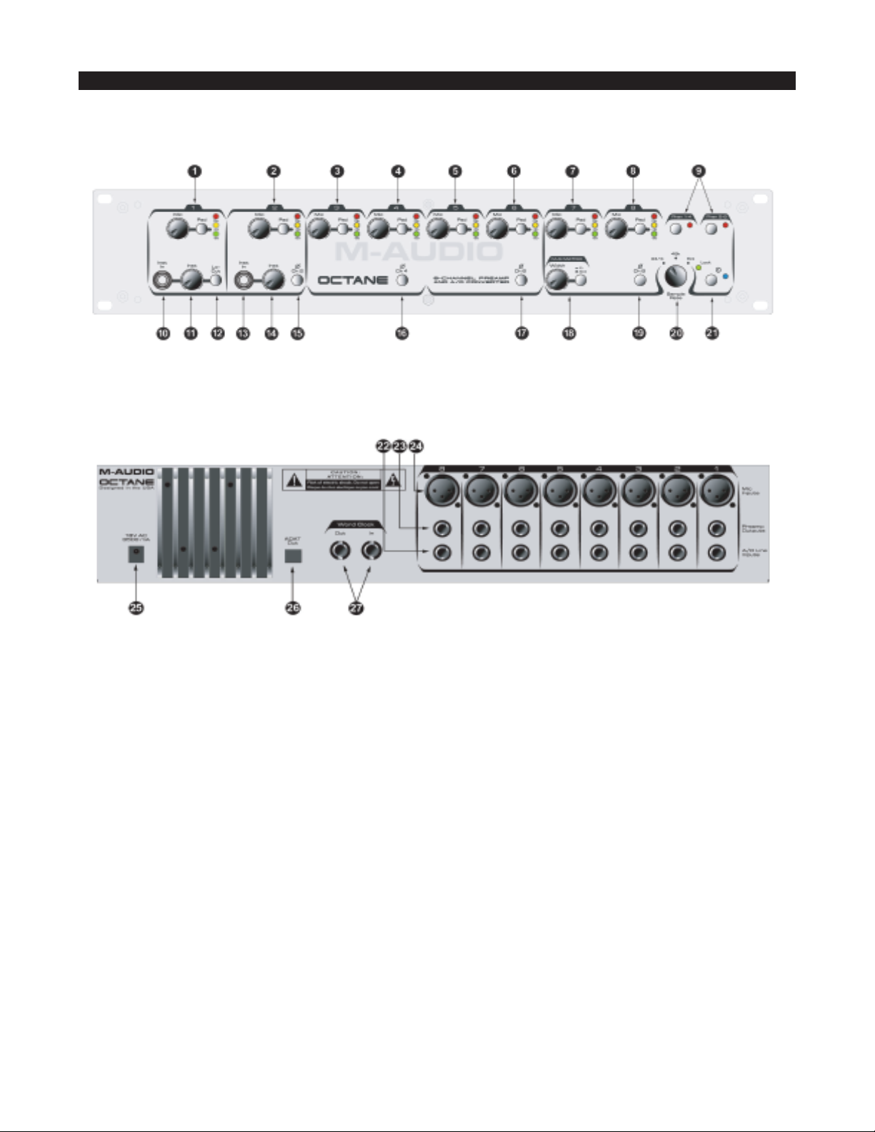
Controls and Connectors
Front Panel Diagram
Rear Panel Diagram
Front Panel Descriptions
1. Channel 1 Level Controls –
Mic Level – Controls the input level of the channel’s mic preamp. Turn fully counter-clockwise for minimum gain, fully clockwise for
maximum gain.
Pad – Pressing and locking this switch to the IN position inserts a 20dB pad into the signal path. Use the pad when your input level is
too hot, as indicated by the Red Clip LED.
LED Level Meter – Three segment input level meter:
Green – Indicates input level of -20dB
Yellow – Indicates input level of -10dB
Red – Input level of 0dB indicates clipping. Triggers at -3dB.
A word about metering: Different hardware devices and software applications employ different metering schemes. For example, the
ADAT and some DAW programs will show level on their input meters at as low as -40dB, whereas Octane’s meters register at -20dB. It
is entirely possible that your DAW or other recording device will display a reading at very low audio levels, even when Octane’s meters
do not show a level.
In digital recording, particularly with 24-bit digital technology, it is important to achieve as hot a signal as possible without exceeding
0dB. The higher an input level you record with, the better the resolution of your digital recording. Do not go over 0dB, however, or your
signal will be distorted.
3
Page 4

2. Channel 2 Level Controls – Identical to Channel 1 Level Controls, these control the settings for channel 2. Refer to Channel 1
description for more details.
3. Channel 3 Level Controls – Identical to Channel 1 Level Controls, these control the settings for channel 3. Refer to Channel 1
description for more details.
4. Channel 4 Level Controls – Identical to Channel 1 Level Controls, these control the settings for channel 4. Refer to Channel 1
description for more details.
5. Channel 5 Level Controls – Identical to Channel 1 Level Controls, these control the settings for channel 5. Refer to Channel 1
description for more details.
6. Channel 6 Level Controls – Identical to Channel 1 Level Controls, these control the settings for channel 6. Refer to Channel 1
description for more details.
7. Channel 7 Level Controls – Identical to Channel 1 Level Controls, these control the settings for channel 7. Refer to Channel 1
description for more details.
8. Channel 8 Level Controls – Identical to Channel 1 Level Controls, these control the settings for channel 8. Refer to Channel 1
description for more details.
9. Phantom Power Switches and LEDs – Pressing and locking the Phan 1-4 switch to the IN position activates +48V phantom power
to rear-panel XLR Inputs 1-4. Pressing and locking the Phan 5-8 switch to the IN position activates +48V phantom power to rear-panel
XLR Inputs 5-8. The switches’ associated LEDs light to indicate that phantom power is active for those channels.
10. Channel 1 Instrument Input – Ultra high impedance, unbalanced instrument-level input on 1/4" TS jack.
NOTE: Inserting a TS connector in this input will override any signal present at Channel 1 Mic Input.
11. Channel 1 Instrument Level – Controls the input level of the channel’s Instrument preamp. Turn fully counter-clockwise for
minimum gain, fully clockwise for maximum gain.
12. Channel 1 Low Cut Switch – Pressing and locking this switch in the IN position engages the channel’s Low Cut filter, attenuating
the Low Frequency signal of 80Hz and below at a rate of 12dB per octave.
13. Channel 2 Instrument Input – Ultra high impedance, unbalanced instrument level input on 1/4" TS jack.
NOTE: Inserting a TS connector in this input will override any signal present at Channel 2 Mic Input.
14. Channel 2 Instrument Level – Controls the input level of the channel’s instrument preamp. Turn fully counter-clockwise for minimum
gain, fully clockwise for maximum gain.
15. Channel 2 Phase Reverse – Pressing and locking this switch to the IN position reverses the phase of the output signal on this
channel. This is useful when using two adjacent channels to mic a stereo source.
16. Channel 4 Phase Reverse – Pressing and locking this switch to the IN position reverses the phase of the output signal on this
channel. This is useful when using two adjacent channels to mic a stereo source.
17. Channel 6 Phase Reverse – Pressing and locking this switch to the IN position reverses the phase of the output signal on this
channel. This is useful when using two adjacent channels to mic a stereo source.
18. M-S Matrix Switch and Width Control – Pressing and locking the M-S Matrix Switch to the IN position engages the Mid-Side matrix
encoding circuitry for channels 7 and 8. Rotating the Width Control regulates the apparent width of the Mid-Side stereo signal.
NOTE: When using channels 7 and 8 in M-S Matrix mode, connect your Mid (Cardioid) microphone to channel 7 and your Side
(Figure-8) mic to channel 8.
19. Channel 8 Phase Reverse – Pressing and locking this switch to the IN position reverses the phase of the output signal on this
channel. This is useful when using two adjacent channels to mic a stereo source.
20. Sample Rate Selector – This three-position selector switch determines the sample rate of Octane’s digital outputs. Selecting 44.1k or
48k sets Octane’s digital output to the selected sample rate, using Octane’s internal clock. Selecting Ext will lock Octane’s digital output
to the sample rate being fed to Octane’s rear panel word clock input from an external digital source.
21. Power Switch and LED – Pressing and locking this switch to the IN position powers Octane on. The adjacent Power LED lights to
indicate powered-on status. Pressing the switch again will release it and power Octane off.
NOTE: Always use caution when powering on a preamp or other audio device, as they can produce audio peaks that can
damage speakers. Turn your monitors down fully, or keep them powered off, until the unit is powered on.
4
Page 5
Rear Panel Descriptions
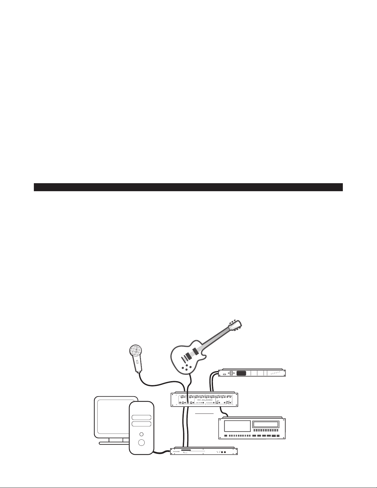
ADAT
Wordclock Device
Delta 1010
Computer
in
out
out
To XLR
Mic In
To Inst In
From
Preamp
Outs
Octane
22. A/D Line Inputs 1-8 – These are balanced/unbalanced direct analog inputs to Octane’s ADC (Analog/Digital Converters) on 1/4" TRS
connectors. These inputs are half-normalled to Octane’s Preamp Outputs, allowing them to function as eight independent channel insert
returns, or as a standalone ADC (Analog to Digital Converter). Plugging a connector into the A/D Line Input will interrupt the signal from
the XLR input to the lightpipe output, but plugging a connector into the Line Output will not.
23. Preamp Outputs 1-8 – These are balanced/unbalanced direct analog outputs for each preamp channel on 1/4" TRS connectors.
These outputs are half-normalled to Octane’s A/D Line Inputs, allowing them to function as eight independent channel insert sends.
Plugging a connector into the A/D Line Input will interrupt the signal from the XLR input, but plugging a connector into the Line Output
will not.
24. Mic Inputs 1-8 – These are balanced XLR mic-level inputs to Octane’s eight microphone preamps. Their levels are controlled by the
associated channel’s front panel Mic Level Control.
NOTE: When a 1/4" connector is inserted into channel 1 or 2 Inst In, the XLR Mic Input for those channels is disabled.
25. Power Input – Connect Octane’s 18VAC 3500 mA power supply to this input.
26. ADAT Output – ADAT 8-channel digital output accepts a standard optical cable with TOSLink connector. This output gets it’s signal
either directly from the mic/instrument inputs, or from the device connected to the A/D Line Inputs.
27. Word Clock I/O – Word clock input and output on BNC connectors.
Connections
Connect your balanced inputs to Octane’s rear panel XLR Mic Inputs 1 - 8.
In many cases, you will be using Octane to connect to your Digital Audio Workstation environment. Connect an ADAT optical cable from
Octane’s rear-panel ADAT Output to the ADAT input on your computer’s digital audio interface, digital mixer, or other ADAT-compatible
digital recording device.
If your digital audio interface offers word clock I/O, connect them to Octane’s Word Clock In and Out using BNC connectors on coaxial cables.
Octane’s A/D Line Inputs can be used as insert returns in conjunction with the Preamp Outputs, or as a standalone A/D converter.
NOTE: Inserting a connector in a channel’s A/D Line Input will override the input from the Mic (XLR) Input.
Octane’s Preamp Outputs can be used as insert sends in conjunction with the A/D Line Inputs, or connected to a mixer’s analog inputs.
You may also use the Octane’s Preamp Outputs to connect directly to the analog line inputs of a computer sound card (such as the Delta
1010, both by M-Audio).
You can connect instrument level sources to channels 1 and 2 Instrument Inputs.
NOTE: The Instrument Inputs override those channels’ Mic Inputs; inserting a connector in either channel’s Inst In will disable
that channel’s Mic (XLR) Input.
5
Page 6

Using the Octane
Setting Gain
Octane’s low-noise microphone preamps provide up to 70dB of gain on the XLR mic inputs and up to 50dB of gain on the TRS instrument
inputs. Connect your microphones and/or instruments to Octane’s inputs with the associated channels set to minimum gain, then raise
the gain slowly while feeding it a live signal (by testing the mic or playing the instrument). A good input level will light the channel’s
–20dB (Green) LED and –10dB (Yellow) LEDs. Note that when the Clip (Red) LED lights, it is indicating that the signal is approximately 3dB below clipping. Ideally, the Clip LED should flicker briefly on strong input signal peaks, but not light steadily, as this will lead to an
overloaded, distorted signal.
Note that Octane’s level meters are only an indication of the input level from your audio source (microphone, instrument, etc.) into Octane’s
preamps. It is equally important to check the level at the inputs of your DAW or other digital recording device.
A word about metering: Different hardware devices and software applications employ different metering schemes. For example, the
ADAT and some DAW programs will show level on their input meters at as low as –40dB, whereas Octane’s meters register at -20dB.
It is entirely possible that your DAW or other recording device will display a reading at very low audio levels, even when Octane’s meters
do not show a level.
In digital recording, particularly with 24-bit digital technology, it is important to achieve as hot a signal as possible without exceeding
0dB. The higher an input level you record with, the better the resolution of your digital recording will be. Do not go over 0dB or your signal
will be distorted.
Using the Pad Switches
If your channel input signal is too hot, causing the red Clip LED to light steadily, pressing and locking the PAD switch in the IN position will
insert a 20dB pad into the signal chain.
NOTE: As with most preamplification, it is always advisable to turn down your monitors before turning on any PAD switch.
Instrument Inputs (Ch 1 and 2)
Channels 1 and 2 offer front panel Instrument Inputs on unbalanced 1/4" TS connectors. These Instrument Inputs employ separate
instrument preamps, providing higher input impedance and far better Signal-to-Noise Ratio than the shared Mic/Instrument preamp
combinations available in most preamps. The level for these Instrument Inputs is controlled by that channel’s Instrument Level control.
Turn fully counter-clockwise for minimum gain, fully clockwise for maximum gain.
NOTE: When a TS connector is inserted in channel 1 or 2 Inst In, that channel’s Mic Input is disabled.
Using the Preamp Outputs
Octane’s eight Preamp Outputs are direct analog outputs on balanced/unbalanced 1/4" TRS connectors. They can be used to connect
directly to an analog input on a computer sound card, mixing console or other analog device.
The Preamp Outputs are half-normalled to their associated A/D Line Inputs. Plugging a connector into the A/D Line Input will interrupt
the signal from the XLR input, but plugging a connector into the Line Output will not. This allows you to use them as channel insert sends,
to connect a compressor, limiter, or other analog signal processor.
Using the A/D Line Inputs
Octane’s eight A/D Line Inputs are direct high-level inputs on balanced/unbalanced 1/4" TRS connectors. These inputs bypass the
channel microphone preamps, providing direct connection to Octane’s ADC (Analog to Digital Converters). This makes it possible to use
Octane as a standalone analog-to-digital converter.
The A/D Line Inputs are half-normalled to their associated Preamp Outputs. Plugging a connector into the A/D Line Input will interrupt
the signal from the XLR input, but plugging a connector into the Line Output will not. This allows you to also use them as channel insert
returns, to return signal from a compressor, limiter, or other analog signal processor.
To use the Preamp Outputs and A/D Line Inputs as inserts, connect the channel’s Preamp Output to the input of your insert device (e.g.,
compressor, noise gate, etc.). Connect the device’s output to the channel’s A/D Line Input.
Lo-Cut Switch (Ch 1)
In some cases, foot movements, mic stand noise, traffic and other environmental elements can create unwanted low frequency noise
6
Page 7
and rumbling. Pressing and locking the Lo-Cut Switch in the IN position will insert a high-pass filter which will attenuate frequencies
M
+S
-S
below 80Hz at a rate of -12dB per octave.
Phase Inversion Switches (Ch 2, 4, 6, 8)
When using a stereo (two microphone) configuration, it is not uncommon for the two channels to have phase-cancellation problems.
This can often be corrected by reversing the phase of one of the two microphones.
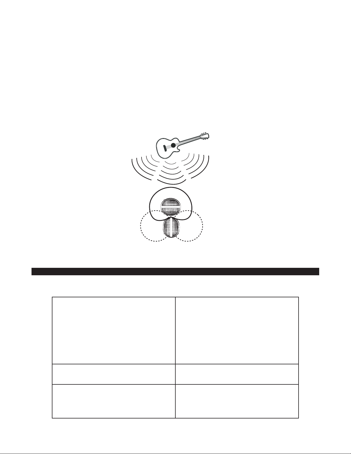
NOTE: The best way to hear the effect of phase reversal is to listen to a stereo source, such as an acoustic guitar being
recorded with two microphones. Pan the channels hard left and hard right, and listen as you press the even-numbered
channel’s Phase switch. You should hear the stereo sound “open up,” and become more wide and “solid” sounding in one
position or the other.
Phantom Power Switches
Condenser microphones need to receive a DC voltage (generally +48V) from an external source in order to generate an output signal.
While some condenser mics come with their own power supplies or internal batteries, the majority require phantom power to be
supplied from the preamp or mixing console.
Pressing and locking the Phan 1-4 or Phan 5-8 switches to the IN position will activate phantom power, supplying +48VDC to the
associated group of four input channels. Always make certain to connect your microphone before turning on phantom power.
Conversely, make certain to turn OFF phantom power before disconnecting your microphone.
Most dynamic microphones are unaffected by phantom power, however some (primarily older) ribbon microphones can be damaged by
it. Do not use phantom power with unbalanced microphones. When in doubt, check with the manufacturer of the microphone in question.
M-S Matrix
NOTE: When using channels 7 and 8 in M-S Matrix mode, connect your Mid (Cardioid) microphone to channel 7 and your Side
(Figure-8) mic to channel 8.
Pressing and locking the M-S Matrix switch in the IN position engages the M-S matrix encoding circuitry on channels 7 and 8. The Width
control regulates the relative balance of the Mid and Side signals. Turn it fully counter-clockwise for minimum Side signal (less apparent
width), or fully clockwise for maximum Side signal (more apparent width).
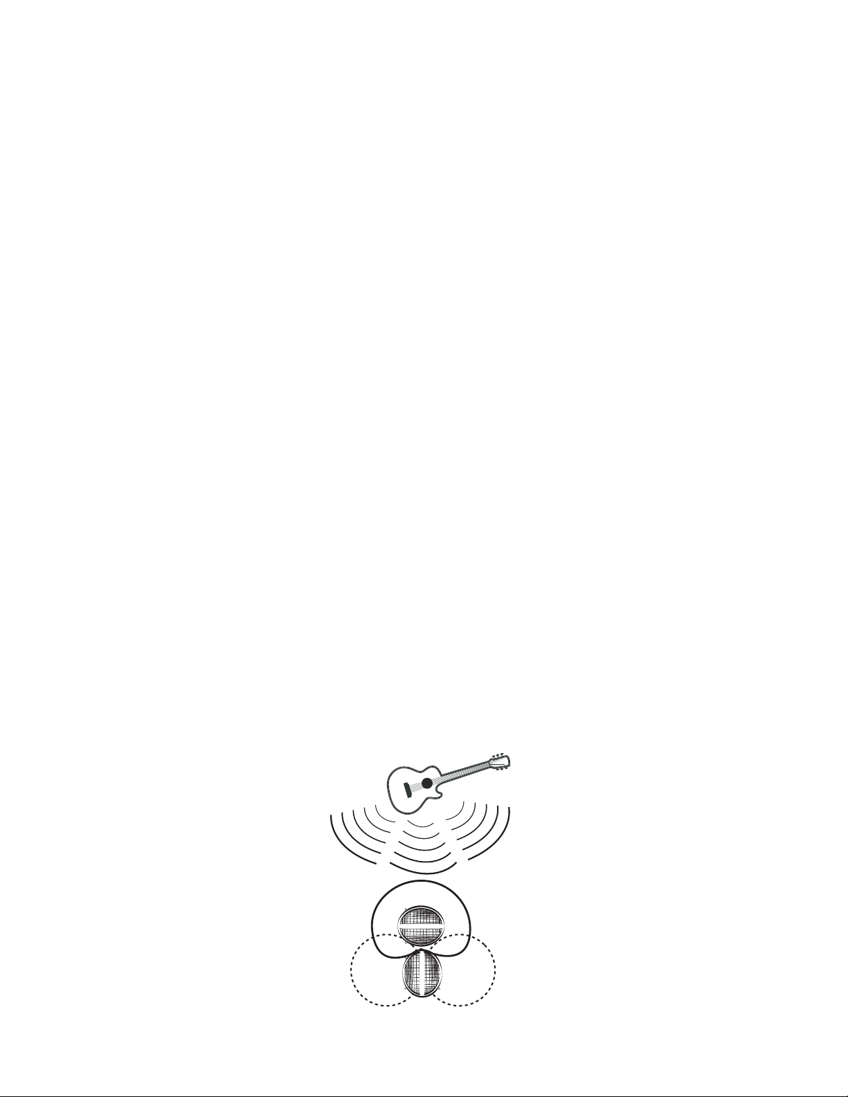
A word about M-S Matrixing: The M-S (Mid-Side) miking technique was created by renowned inventor Alan Dower Blumlein, credited as
the originator of stereophonic recording. While the more commonly-used X-Y miking techniques involve placing two microphones in a
coincident pattern (usually aimed approximately 45 degrees left and right of the intended source), M-S miking aims one microphone
directly at the source, using a cardioid pickup pattern; the second microphone is aimed sideways using a bi-directional figure-eight
pickup pattern. The M-S matrix encoder then sums the Mid and Side signals (M+S), sending it to the left channel, and subtracts the
signals (M-S), sending it to the right channel. By adjusting the relative balance of Mid and Side signals (with Octane, this is accomplished
with the Width control), the optimal stereo image can be created. A major advantage of M-S miking is mono compatibility, in that there
is less potential for phase cancellation when the stereo signal is summed to mono, which is a risk with X-Y technique.
The illustration below shows the pickup patterns of two microphones arranged in M-S stereo placement.
7
Page 8

Sample Rate Selector
Using the Sample Rate Selector, Octane’s digital output can be set to 44.1kHz or 48kHz, using its own internal digital clock, or it can be
set to slave to the clock rate being received at the Word Clock Input.
The Lock LED will glow when Octane is set to Ext and has locked to an external sample clock.
NOTE: Some recording devices do not automatically lock to the incoming word clock signals on the digital input, even if the
device is set to lock to the word clock signal on the digital input. You must set those devices to the sample rate you are sending
them in order for them to lock correctly. Also note that not all hardware will indicate proper sample rate when slaved to an
external source, even though they may be clocked properly in the digital stream. It is good practice to set a consistent sample
rate across all digital gear before assigning Master and Slave devices, particularly with legacy gear.
Troubleshooting
Octane is a precision-designed device, and has been engineered and assembled to give you trouble-free operation. Nonetheless, if you
experience any problems, here are a few things to check:
Problem 1: Channel LEDs show no input level.
Solution 1:
< Make sure nothing is connected to the channel’s A/D Line Input.
< Make sure you have a valid input signal.
< Make sure you have sufficient level, and that the Pad feature is not enabled
< If you are using a condenser mic, make sure phantom power is activated for that channel.
< Check your input cable for damage.
Problem 2: Channel 1 and 2 LEDs show no input level.
Solution 2: Make sure nothing is connected to the channel’s Instrument Inputs.
Problem 3: No digital output, or noisy digital output.
Solution 3: Check the Sample Rate Selector to see if it matches the settings on your DAW or other digital recording device.
8
Page 9

Specifications
Analog Features:
8 balanced microphone inputs with:
< 20dB input pads
< 50dB continuously variable gain
< Phantom power (48V) with indicator for channels 1 through 4
< Phantom power (48V) with indicator for channels 5 through 8
< System throughput gain (balanced in / balanced out): 19dB to 70dB (-1dB to 50dB with 20dB pad engaged)
< Frequency Response: 20Hz-20kHz, +/- 0.11 dB; mid gain
< Signal-to-Noise Ratio: 120dB, A-weighted; mid gain
< Dynamic Range: 120dB, A-weighted; mid gain
< THD+N: 0.00041% @ -107dB, 1dB below clipping, 22Hz-22kHz; mid gain
< EIA noise rating: -129dBu @ max gain, 600 ohms, 22Hz-22kHz
< Input impedance: 2850 ohms with pad dis-engaged; 3600 ohms with pad engaged
2 unbalanced instrument inputs with:
< Input Impedance: 3M Ohms
< Continuously variable gain: 44dB
< Instrument inputs automatically engage when plugged in
< System throughput gain: 6dB to 50dB (balanced out); 0dB to 44dB (unbalanced out)
< Frequency Response: 20Hz-20kHz, +/- 0.03 dB; mid gain
< Signal-to-Noise Ratio: 133dB, A-weighted; mid gain
< Dynamic Range: 133dB, A-weighted; mid gain
< THD+N: 0.0018% @ -95dB, 1dB below clipping, 22Hz-22kHz; mid gain
MS matrix (enabled; width set mid position):
< Ch. 7 & 8 inputs are M & S respectively
< Ch. 7 & 8 outputs are L & R respectively
< Matrix: L=M+S/3 and R=M_S/3
Additional analog:
< Maximum rated analog output (digital clip): Balanced: +26dBu; Unbalanced: +20dBu
< Rear Line Input impedance: 20K Ohms balanced, 13.3K Ohms unbalanced
< Output impedance: 600 Ohms balanced
< Channel 1 bass cut switch: -12dB/octave below 80Hz
< Phase inverter switch on channels 2, 4, 6 & 8
Digital Features:
8 balanced/unbalanced direct A/D analog inputs:
< Output: Lightpipe; 8 channel, 24-bit, ADAT optical format
< Frequency Response: 20Hz-20kHz, +/- 0.04dB
< Signal-to-Noise Ratio: 110dB, A-weighted
< Dynamic Range: 110dB, A-weighted
< THD+N: 0.00067% @ -103dB, -1dBFS, 22Hz-22kHz
< Digital clip level at direct inputs: +20dBu
< Channel quasi-peak level indicators light 3dB, 10dB & 20dB below digital clip.
< Supported sample rates (manually switched): 44.1kHz, 48kHz & external (word clock)
< Word clock Input and Output with lock indicator, lock range: 33kHz to 59kHz
Power Requirements:
18 VAC (16.5 VAC minimum) @ 3.5A inline power supply
9
Page 10

Warranty
Register your Octane online to receive FREE product updates and be entered to win FREE M-Audio gear
(www.m-audio.com/register).
M-AUDIO warrants this product, under normal use, to be free of defects in materials and workmanship for a period of One (1) Year
from date of purchase, so long as: the product is owned by the original purchaser, with proof of purchase from an authorized MAUDIO dealer and, the product has been registered to the original purchaser, the purchaser having returned to M-AUDIO the
completed product warranty card. This warranty explicitly excludes power supplies and included cables which may become
defective as a result of normal wear and tear.
In the event that M-AUDIO receives, from an original purchaser and within the warranty coverage period, written notice of defects
in materials or workmanship, M-AUDIO will either replace the product, repair the product, or refund the purchase price at its
option. In the event repair is required, shipment to and from M-AUDIO and possible nominal handling charges shall be born by
the purchaser. In the event that repair is required, a Return Authorization number must be obtained from M-AUDIO. After this
number is obtained, the unit should be shipped back to M-AUDIO in a protective package with a description of the problem and
the Return Authorization clearly written on the package.
In the event that M-AUDIO determines that the product requires repair because of user misuse or regular wear, it will assess a
fair repair or replacement fee. The customer will have the option to pay this fee and have the unit repaired and returned, or not
pay this fee and have the unit returned un-repaired.
The remedy for breach of this limited warranty shall not include any other damages. M-AUDIO will not be liable for consequential,
special, indirect, or similar damages or claims including loss of profit or any other commercial damage, even if its agents have
been advised of the possibility of such damages, and in no event will M-AUDIO's liability for any damages to the purchaser or any
other person exceed the price paid for the product, regardless of any form of the claim. M-AUDIO specifically disclaims all other
warranties, expressed or implied. Specifically, M-AUDIO makes no warranty that the product is fit for any particular purpose.
This warranty shall be construed, interpreted, and governed by the laws of the state of California. If any provision of this warranty
is found void, invalid or unenforceable, it will not affect the validity of the balance of the warranty, which shall remain valid and
enforceable according to its terms. In the event any remedy hereunder is determined to have failed of its essential purpose, all
limitations of liability and exclusion of damages set forth herein shall remain in full force and effect.
Contact M-Audio
M-AUDIO U.S.
5795 Martin Road, Irwindale, CA 91706-6211, U.S.A.
Sales Information: 626-633-9050
Sales Information (email): info@m-audio.com
Tech Support: 626-633-9055
Tech Support (email): techsupt@m-audio.com
Fax: 626-633-9060
Internet Home Page: http://www.m-audio.com
M-AUDIO U.K.
Unit 5, Saracen Industrial Estate, Mark Road, Hemel Hempstead, Herts HP2 7BJ, England
Sales Information: 44 (0) 144 241 6590
Sales Information (email): info@maudio.co.uk
Technical Support: 44 (0) 871 717 7102
Technical Support (email): richard@maudio.freeserve.co.uk
Fax: 44 (0) 144 224 6832
Internet Home Page: http://www.maudio.co.uk
M-AUDIO U.K.
Unit 5, Saracen Industrial Estate, Mark Road, Hemel Hempstead, Herts HP2 7BJ, England
Sales Information: 0810 001 105
Sales Information (email): info@m-audio-france.com
Technical Support: 0820 00 731
Technical Support (email): support@m-audio-france.com
Fax: 44 (0) 144 224 6832
Internet Home Page: http://www.maudio.co.uk
M-AUDIO Deutschland (Germany)
Kuhallmand 34, D-74613 Ohringen, Germany
Sales Information: 49 7941 98 7000
Sales Information (email): info@m-audio.de
Technical Support: 49 7941 98 70030
Technical Support (email): support@m-audio.de
Fax: 07941 98 70070
Internet Home Page: http://www.m-audio.de
M-AUDIO Canada
1400 St-Jean Baptiste Ave. #150, Quebec City, QC G2E 5B7, Canada
Tel: 418-872-0444
Fax: 418-872-0034
Email: midimancanada@m-audio.com
Internet Home Page: http://www.m-audio.ca
M-AUDIO Japan
Annex Buliding 6F, 2-18-10 Marunouchi, Naka-Ku, Nagoya 460-0002, Japan
Tel: 81 52 218 3375
Fax: 81 52 218 0875
Technical Support: 0820 00 731
Email: info@m-audio.co.jp
Internet Home Page: http://www.m-audio.co.jp
10
Page 11

Français -
Introduction
Merci d’avoir choisit le préamplificateur de microphone/instrument M-Audio Octane. Octane vous offre huit canaux indépendants de
préamplification micro à gain élevé et ultra faible bruit dans un solide châssis au format rack 2U. Doté de huit entrées sur connecteurs
XLR et de huit canaux de sortie optique ADAT, Octane a été conçu pour constituer le complément analogique idéal pour votre
environnement d’enregistrement numérique.
Octane présente une foule multitude de fonctionnalités professionnelles que l’on ne trouve habituellement que sur de les préamplis
micro sophistiqués et beaucoup plus onéreux : préamplis d’instrument indépendants sur les canaux 1 et 2, encodage “Mid-Side“ sur les
canaux 7 et 8, alimentation fantôme +48V commutable, E/S word clock sur fiches BNC, etc. Avec jusqu’à70dB de gain et 129dBm de
niveau de bruit EIA, Octane est une outil multicanal hautes performances, avec à un prix très abordable, idéal aussi bien pour les home
studios que pour les studios professionnels.
Contenu de la boîte
L’emballage d’Octane contient les éléments suivants :
< Le préamplificateur microphone/instrument Octane
< Un bloc d’alimentation 18V CA 3500mA
< Ce Guide de l’utilisateur
A propos d’Octane
Octane est un préampli micro multicanal offrant huit canaux de préamplification professionnelle à faible bruit bruit bas et gain élevé
dans un châssis rack 2U.
Chaque canal dispose de son propre contrôle de niveau d’entrée, de son atténuateur 20dB et de son indicateur de niveau LED à 3
segments. Les entrées XLR symétriques se trouvent sur le panneau arrière. Octane offre de plus huit sorties préampli analogiques sur
connecteurs jack TRS 6,35 mm symétriques/asymétriques, ainsi que 8 canaux d’entrée de ligne A/N. Ces entrées sont seminormalisées (le branchement d’un connecteur sur l’entrée de ligne A/N interrompt le signal entre l’entrée XLR et la sortie optique ADAT
lightpipe, ce qui n’est pas le cas si l’on branche un connecteur dans la sortie de ligne) et peuvent être utilisées en tant que retours
d’insertion ou pour permettre à Octane de fonctionner comme convertisseur A/N.
Octane est également équipé d’entrées frontales de niveau instrument haute impédance sur les canaux 1 et 2. Ses préamplis
indépendants et son contrôle de niveau assurent des performances supérieures et un meilleur rapport signal-bruit. Les canaux 7 et 8
offrent un circuit d’encodage M-S pour enregistrement stéréo Mid-Side. Chacun des canaux pairs d’Octane (canaux 2, 4, 6 et 8) offre un
interrupteur d’inversion de phase facilitant leur utilisation en mode stéréo. L’alimentation fantôme +48V est commutable sur deux
groupes de quatre canaux.
Caractéristiques
< Huit canaux de préamplification micro haute qualité à faible bruit
< 8 entrées symétriques XLR
< Chaque canal est pourvu d’une commande de niveau, d’un atténuateur et d’un indicateur LED à trois segments
< Alimentation fantôme +48V commutable
< Deux entrées instrument asymétriques haute impédance sur la face avant, avec contrôles de niveau indépendants
< Encodage MS (Mid-Side) sur les canaux 7 et 8
< Huit sorties de préamplificateur symétriques/asymétriques sur connecteurs jacks TRS 6,35 mm
< Huit entrées ligne A/N de canal symétriques/asymétriques sur connecteurs jack TRS 6,35 mm pouvant être utilisées comme
insertions ou convertisseurs A/N autonomes
< Interrupteur d’inversion de phase sur canaux pairs, filtre coupe-bas sur le canal 1
< Sortie numérique ADAT lightpipe
< Sélecteur de fréquence d’échantillonnage/horloge externe sur la face avant
< E/S word clock avec boucle de phase verrouillée à faible “jitter”
11
Page 12

Contrôles et connecteurs
Face avant
Face arrière
Légende face avant
1. Commandes de niveau du Canal 1 –
Niveau micro
au minimum, et complètement vers la droite pour obtenir le gain maximum.
Atténuateur – Lorsque ce bouton est enfoncé, une réduction de 20dB du gain d’entrée appliquée. Utilisez l’atténuateur quand votre
niveau d’entrée est trop élevé, selon l’indication du témoin LED rouge “
Témoin LED de niveau – Indicateur de niveau d’entrée à trois segments :
Un mot à propos de l’indication de niveau : Les indications de niveaux peuvent différer selon les appareils et les logiciels. Par
exemple, un enregistreur ADAT et certaines stations audionumériques indiquent un niveau dès -40dB, tandis qu’Octane ne commence
à en rendre compte qu’à partir de -20dB. Il est donc tout à fait possible que votre station audionumérique (ou tout autre appareil
d’enregistrement) détecte une présence de signal à un niveau audio très faible alors que l’Octane n’affiche encore rien.
Dans le domaine de l’enregistrement numérique, et particulièrement avec la technologie numérique 24 bits, il est important d’atteindre
un signal aussi élevé que possible sans dépasser 0dB. Plus le niveau d’entrée avec lequel vous enregistrez est élevé, meilleure sera la
résolution de votre enregistrement numérique. Toutefois, n’allez pas au-delà de 0dB, car votre signal serait détérioré.
– Contrôle le niveau d’entrée du préampli micro du canal. Tournez-le complètement vers la gauche pour réduire le gain
Clip” (écrêtage).
Vert – Indique un niveau d’entrée de -20dB
Jaune – Indique un niveau d’entrée de -10dB
Rouge – Un niveau d’entrée de 0dB est synonyme d’écrêtage. Il s’allume à -3dB.
12
Page 13

2. Commandes de niveau du Canal 2 – Identiques à celles de la section Commandes de niveau du Canal 1, elles déterminent
les réglages du canal 2. Reportez-vous aux descriptions du Canal 1 pour plus de détails.
3. Commandes de niveau du Canal 3 – Identiques à celles de la section Commandes de niveau du Canal 1, elles déterminent
les réglages du canal 3. Reportez-vous aux descriptions du Canal 1 pour plus de détails.
4. Commandes de niveau du Canal 4 – Identiques à celles de la section Commandes de niveau du Canal 1, elles déterminent
les réglages du canal 4. Reportez-vous aux descriptions du Canal 1 pour plus de détails.
5. Commandes de niveau du Canal 5 – Identiques à celles de la section Commandes de niveau du Canal 1, elles déterminent
les réglages du canal 5. Reportez-vous aux descriptions du Canal 1 pour plus de détails.
6. Commandes de niveau du Canal 6 – Identiques à celles de la section Commandes de niveau du Canal 1, elles déterminent
les réglages du canal 6. Reportez-vous aux descriptions du Canal 1 pour plus de détails.
7. Commandes de niveau du Canal 7 – Identiques à celles de la section Commandes de niveau du Canal 1, elles déterminent
les réglages du canal 7. Reportez-vous aux descriptions du Canal 1 pour plus de détails.
8. Commandes de niveau du Canal 8 – Identiques à celles de la section Commandes de niveau du Canal 1, elles déterminent
les réglages du canal 8. Reportez-vous aux descriptions du Canal 1 pour plus de détails.
9. Interrupteurs et témoins LED d’alimentation fantôme – Si vous enfoncez l’interrupteur Phan 1-4, vous activez l’alimentation
fantôme +48V vers les entrées XLR 1 à 4 de la face arrière. Si vous enfoncez l’interrupteur
Phan 5-8, vous activez l’alimentation fantôme
+48V vers les entrées XLR 5 à 8 de la face arrière. Les témoins LED correspondant aux interrupteurs s’allument pour indiquer que
l’alimentation fantôme est activée sur ces canaux.
10. Entrée instrument canal 1 – Entrée instrument asymétrique à haute impédance (connecteur jack TS 6,35mm).
REMARQUE : si vous insérez un connecteur TS dans cette entrée, vous annulez tout signal présent à l’entrée micro du canal 1.
11. Niveau instrument canal 1 – Contrôle le niveau d’entrée du préampli instrument du canal. Tournez-le complètement vers la
gauche pour réduire le gain au minimum, et complètement vers la droite pour obtenir le gain maximum.
12. Interrupteur du filtre coupe-bas du canal 1 – Lorsque vous enfoncez cet interrupteur, le filtre coupe-bas du canal s’active,
atténuant les signaux basses fréquences inférieurs ou égaux à 80Hz (12dB par octave).
13. Entrée instrument canal 2 – Entrée instrument asymétrique à impédance ultra élevée (connecteur jack TS 6,35mm).
REMARQUE : si vous insérez un connecteur TS dans cette entrée, vous annulez tout signal présent à l’entrée de micro canal 2.
14. Niveau instrument canal 2 – Contrôle le niveau d’entrée du préampli instrument du canal. Tournez-le complètement vers la
gauche pour réduire le gain au minimum, et complètement vers la droite pour obtenir le gain maximum.
15. Inversion de phase canal 2 – Lorsque cet interrupteur est verrouillé en position enfoncée, la phase du signal de sortie s’inverse
sur ce canal. Cet interrupteur s’avère utile lorsque sont utilisés deux canaux adjacents pour enregistrer une source stéréo.
16. Inversion de phase canal 4 – Lorsque cet interrupteur est verrouillé en position enfoncée, la phase du signal de sortie s’inverse
sur ce canal. Cet interrupteur s’avère utile lorsque sont utilisés deux canaux adjacents pour enregistrer une source stéréo.
17. Inversion de phase canal 6 – Lorsque cet interrupteur est verrouillé en position enfoncée, la phase du signal de sortie s’inverse
sur ce canal. Cet interrupteur s’avère utile lorsque sont utilisés deux canaux adjacents pour enregistrer une source stéréo.
18. Interrupteur M-S Matrix et contrôle d’amplitude – Lorsque l’interrupteur M-S Matrix est verrouillé en position enfoncée, le
circuit d’encodage Mid-Side est enclenché pour les canaux 7 et 8. Tourner le contrôle
Width (amplitude) permet de réguler l’amplitude
apparente du signal stéréo Mid-Side.
REMARQUE : lorsque vous utilisez les canaux 7 et 8 en mode de matrice M-S, connectez un micro central (cardioïde) sur le
canal 7 et un micro latéral (diagramme en 8) sur le canal 8.
19. Inversion de phase canal 8 – Lorsque cet interrupteur est verrouillé en position enfoncée, la phase du signal de sortie s’inverse
sur ce canal. Cet interrupteur s’avère utile lorsque sont utilisés deux canaux adjacents pour enregistrer une source stéréo.
20. Sélecteur de fréquence d’échantillonnage – Cet interrupteur à 3 positions permet de déterminer la fréquence
d’échantillonnage des sorties numériques d’Octane. En sélectionnant 44.1kHz ou 48kHz, la fréquence d’échantillonnage de la sortie
numérique d’Octane sera réglée sur la valeur choisie. Si vous sélectionnez Ext, la sortie numérique d’Octane est alors verrouillée sur la
fréquence d’échantillonnage envoyée vers l’entrée word clock de la face arrière à partir d’une source numérique externe.
Le témoin de verrouillage
“Lock“ s’allume quand Octane est réglé sur Ext et verrouillé sur une horloge d’échantillonnage externe.
13
Page 14

REMARQUE : certains appareils d’enregistrement ne se verrouillent pas automatiquement sur le signal word clock présent à
l’entrée numérique, même s’ils ont été configurés en ce sens. Pour qu’ils se verrouillent correctement, vous devrez régler ces
appareils sur l’horloge d’échantillonnage que vous leur envoyez. Prenez également note du fait que tous les appareils
n’indiquent pas la bonne fréquence d’échantillonnage lorsqu’ils sont synchronisés sur une source externe, même si le signal de
synchronisation qu’ils reçoivent est valide. Nous vous recommandons de définir la fréquence d’échantillonnage sur tous vos
appareils numériques avant d’affecter des appareils maître et esclaves, et ce particulièrement avec les équipements anciens.
21. Interrupteur et témoin LED d’alimentation – Enfoncez l’interrupteur pour mettre l’Octane sous tension. Le témoin LED qui lui
correspond s’allume pour signaler que l’appareil est sous tension. Appuyez à nouveau sur l’interrupteur pour le désengager et mettre
Octane hors tension.
REMARQUE : soyez vigilants quand vous allumez un préampli ou tout autre appareil audio, ils sont susceptibles de générer
des crêtes audio pouvant endommager vos haut-parleurs. Baissez complètement le volume de ces derniers ou mettez-les
hors tension le temps que l’Octane soit allumé.
Légende face arrière
22. Entrées de ligne A/N 1 à 8 – Entrées analogiques de niveau ligne directes (+4) symétriques/asymétriques sur des connecteurs
jacks TRS 6,35mm, reliées aux convertisseurs A/N d’Octane. Ces entrées sont semi-normalisées avec les
d’Octane, ce qui leur permet de fonctionner comme huit retours d’insertion de canal indépendants ou comme convertisseur A/N
autonome. Le branchement d’un connecteur sur l’entrée ligne A/N (
lightpipe, ce qui n’est pas le cas si l’on branche un connecteur dans la sortie de ligne (
23. Sorties préampli 1 à 8 – Sorties analogiques directes symétriques/asymétriques sur connecteurs TRS 6,35mm pour chacun des
canaux de préampli. Ces sorties sont semi-normalisées avec les entrées de ligne A/N (
comme huit départs d’insertion de canal indépendants. Le branchement d’un connecteur sur l’entrée ligne A/N (
interrompt le signal issu de l’entrée XLR, ce qui n’est pas le cas si l’on branche un connecteur dans la sortie de ligne (
A/D Line Input) interrompt le signal entre l’entrée XLR et la sortie
Line Output).
A/D Line Inputs) ce qui leur permet de fonctionner
sorties de préampli
A/D Line Input)
Line Output).
24. Entrées micro 1 à 8 – Il s’agit des entrées de niveau micro XLR symétriques reliées aux huit préamplis micro d’Octane. Les
niveaux des entrées micro sont contrôlés par les commandes de niveau
REMARQUE : lorsqu’un connecteur 6,35 mm est inséré dans l’entrée instrument du canal 1 ou 2, l’entrée micro XLR de ces
canaux est désactivée.
25. Connecteur d’alimentation – Connectez le bloc d’alimentation 18V CA 3500mA fourni avec Octane à cette prise.
26. Sortie ADAT – La sortie numérique 8 canaux ADAT accueille un câble optique standard doté d’un connecteur TOSLink. Cette sortie
reçoit son signal soit directement des entrées micro/instrument, soit de l’appareil connecté aux entrées de ligne A/N.
27. E/S word clock – Entrée et sortie word clock sur connecteurs BNC.
Mic de la face avant associés aux canaux correspondants.
Connexions
Connectez vos micros aux entrées micro XLR 1 à 8 de la face arrière d’Octane.
Dans bien des cas, vous utiliserez Octane pour une connexion à votre système d’enregistrement numérique. Connectez un câble
optique ADAT entre la
votre mélangeur numérique ou de tout autre enregistreur numérique compatible ADAT.
Si votre interface audionumérique offre une entrée et une sortie word clock, connectez-les à l’
à l’aide de câbles coaxiaux munis de connecteurs BNC.
entrées de ligne A/N peuvent être utilisées en tant que retours d’insertion en conjonction avec les sorties préampli, ou en tant
Les
que convertisseurs A/N autonomes.
REMARQUE : si vous insérez un connecteur dans une entrée de ligne A/N, vous annulerez le signal de l’entrée micro (XLR).
sortie ADAT de la face arrière d’Octane et l’entrée ADAT de l’interface audionumérique de votre ordinateur, de
entrée et la sortie word clock d’Octane
sorties préampli d’Octane peuvent être utilisées en tant que départs d’insertion en conjonction avec les entrées de ligne A/N,
Les
ou encore connectées aux entrées analogiques d’un mélangeur
entrées de ligne analogiques de votre interface audio (la Delta 1010 de M-Audio par exemple).
Vous avez également la possibilité de connecter des sources de niveau instrument aux
REMARQUE : les entrées instrument annulent les entrées micro de ces canaux ; l’insertion d’un connecteur dans l’entrée
instrument de chacun des canaux désactivera leur entrée micro (XLR).
. Vous pouvez aussi connecter les sorties préampli d’Octane aux
entrées instrument des canaux 1 et 2.
14
Page 15
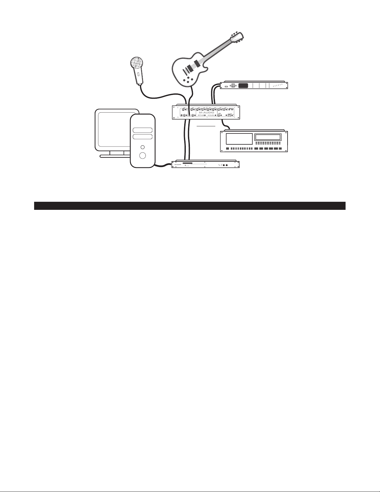
Utilisation d’Octane
ADAT
Wordclock Device
Delta 1010
Computer
in
out
out
To XLR
Mic In
To Inst In
From
Preamp
Outs
Octane
Réglage du gain
Les préamplis micro à faible bruit d’Octane offrent jusqu’à 70dB de gain sur les entrées micro XLR et jusqu’à 50dB de gain sur les entrées
instrument TRS. Connectez vos micros et/ou instruments aux entrées d’Octane, le réglage des canaux correspondants étant en position
minimum, puis augmentez lentement le gain tout en envoyant un signal en direct (en testant le micro ou en jouant d’un instrument). Un
bon niveau d’entrée aura pour effet d’allumer les témoins
LED Clip (écrêtage) (rouge) s’allume, cela indique que le signal se trouve à environ-3dB en dessous de l’écrêtage. L’idéal est que le
témoin d’écrêtage clignote brièvement en cas de crêtes de signal d’entrée élevées, sans s’allumer en continu, car cela témoigne d’un
signal déformé et saturé.
Remarque : les témoins de niveau ne fournissent qu’une indication du niveau d’entrée issu de votre source audio et
parvenant aux préamplis d’Octane. Il est également important de contrôler le niveau aux entrées de votre station
audionumérique ou de votre enregistreur numérique.
Un mot à propos de l’indication de niveau : selon les appareils et les logiciels, les indications de niveaux sont différentes. Par
exemple, un enregistreur ADAT et certaines stations audionumériques indiquent un niveau dès -40dB, tandis qu’Octane ne commence
à en rendre compte qu’à partir de -20dB. Il est donc tout à fait possible que votre station audionumérique (ou tout autre appareil
d’enregistrement) affiche quelque chose à des niveaux audio très faibles quand Octane n’affiche encore rien.
Dans le domaine de l’enregistrement numérique, et particulièrement avec la technologie numérique 24 bits, il est important d’atteindre
un signal aussi élevé que possible sans dépasser 0dB. Plus le niveau d’entrée avec lequel vous enregistrez est élevé, meilleure sera la
résolution de votre enregistrement numérique. Toutefois, n’allez pas au-delà de 0dB, car votre signal serait déformé.
Utilisation des atténuateurs
LED vert (–20dB), et jaune (–10dB) du canal. Sachez que lorsque le témoin
Si votre signal d’entrée est trop élevé et que le témoin rouge d’écrêtage est donc allumé en continu, enfoncez l’interrupteur
atténuateur afin de réduire de 20dB le signal entrant.
d’
REMARQUE : en général, en matière de préamplification, il est préférable d’éteindre les haut-parleurs avant d’activer un atténuateur.
Entrées instrument (Canaux 1 et 2)
Les canaux 1 et 2 offrent des entrées instrument (connecteurs TS 6,35mm) sur la face avant. Ces entrées instrument emploient des
préamplis séparés, assurant ainsi une impédance d’entrée plus élevée et un meilleur rapport signal-bruit que les préamplis
micro/instrument hybrides disponibles sur la plupart des préamplificateurs. Le niveau de ces
15
entrées instrument est déterminé par
Page 16

la commande Instrument Level des canaux correspondants. Tournez-la complètement vers la gauche pour le mettre en position de
gain minimum, et complètement vers la droite pour le mettre en position de gain maximum.
REMARQUE : lorsqu’un connecteur TS est inséré dans l’entrée instrument du canal 1 ou 2, l’entrée micro du canal est désactivée.
Utilisation des sorties de préampli
Les huit sorties de préampli d’Octane sont des sorties analogiques directes sur connecteurs TRS 6,35mm symétriques/asymétriques.
Elles peuvent être utilisées pour la connexion directe à l’entrée analogique d’une interface audio, d’une console de mixage ou de tout
autre appareil analogique.
sorties de préampli sont semi-normalisées avec les entrées ligne A/N qui leur sont associées. Le branchement d’un connecteur
Les
entrée de ligne A/N interrompt le signal de l’entrée XLR, ce qui n’est pas le cas si l’on branche un connecteur dans la sortie de
sur l’
. Cela vous permet donc de les utiliser en tant que départs d’insertion de canal, pour connecter un compresseur, un limiteur ou
ligne
tout autre processeur de signal analogique.
Utilisation des entrées de ligne A/N
Les huit entrées de ligne A/N d’Octane sont des entrées de niveau élevé sur connecteurs TRS 6,35mm symétriques/asymétriques.
Elles évitent les préamplis micro de canal, assurant une connexion directe aux convertisseurs analogique/numérique d’Octane. Cela
rend possible l’utilisation d’Octane en tant que convertisseur analogique/numérique autonome.
entrées de ligne A/N sont semi-normalisées avec les sorties de préampli qui leur sont associées. Le branchement d’un
Les
connecteur sur l’
dans la
signal issu d’un compresseur, un limiteur ou tout autre processeur de signal analogique.
sortie de ligne. Cela vous permet donc de les utiliser également en tant que retours d’insertion de canal, pour retourner le
entrée de ligne A/N interrompt le signal issu de l’entrée XLR, ce qui n’est pas le cas si l’on branche un connecteur
Pour utiliser les
de l’appareil que vous insérez (ex : compresseur, noise gate, etc.). Connectez la sortie de l’appareil sur l’
sorties de préampli et entrées de ligne A/N en tant qu’insertions, connectez la sortie préamplidu canal sur l’entrée
entrée de ligne A/N du canal.
Interrupteur de filtre coupe-bas (canal 1)
Dans certains cas, les mouvements de pied, le pied du micro, la circulation ou d’autres éléments de votre environnement sont
susceptibles de produire des sons basses fréquences indésirables. Si vous enfoncez l’
coupe-bas sera inséré; il atténuera les fréquences en dessous de 80Hz (-12dB par octave).
interrupteur de filtre coupe-bas, un filtre
Commutateurs d’inversion de phase (Canaux 2, 4, 6, 8)
Lorsqu’une configuration stéréo (deux micros) est employée, il n’est pas rare que les deux canaux soient sujets à des problèmes
d’annulation de phase. On peut souvent y remédier en inversant la phase de l’un des deux micros.
REMARQUE : la meilleur manière de vérifier l’effet d’une inversion de phase est d’écouter une source stéréo, par exemple une
guitare acoustique enregistrée par deux micros. Panoramisez les canaux complètement à gauche et complètement à droite
et écoutez le résultat tout en appuyant sur l’interrupteur de phase du canal pair. En principe, le son stéréo doit sembler “ouvert”
et devenir plus large et “solide” dans une position ou dans l’autre.
Interrupteurs d’alimentation fantôme
Les microphones à condensateur ont besoin de recevoir un courant continu (en général +48V) d’une source extérieure afin de pouvoir
générer un signal de sortie. Bien que certains micros à condensateur sont alimentés par un bloc d’alimentation ou par piles, la majorité
requiert une alimentation fantôme issue du préampli ou de la console de mixage.
Si vous enfoncez l’interrupteur
correspondant de quatre canaux d’entrée. Veillez toujours à connecter votre micro avant d’activer l’alimentation fantôme. A l’inverse,
assurez-vous d’avoir désactivé l’alimentation fantôme avant de déconnecter votre micro.
Phan 1-4 ou l’interrupteur Phan 5-8, vous activez l’alimentation fantôme +48V vers le groupe
L’alimentation fantôme n’est pas dangereuse pour la plupart des micros dynamiques. Ce n’est toutefois pas le cas pour certains micros
à ruban (principalement anciens). En cas de doute, consultez le fabricant de votre micro.
Matrice MS (Mid-Side)
REMARQUE : lorsque vous utilisez les canaux 7 et 8 en mode de matrice M-S, connectez un micro central (cardioïde) sur le
canal 7 et un micro latéral (diagramme en 8) sur le canal 8.
16
Page 17
Si vous enfoncez l’interrupteur M-S Matrix, le circuit d’encodage M-S sera enclenché sur les canaux 7 et 8. Le contrôle Width
M
+S
-S
(amplitude) régule la balance relative des signaux centraux (M) et latéraux (S). Tournez-le complètement vers la gauche pour obtenir un
signal latéral S minimum (amplitude moins apparente), et complètement vers la droite pour obtenir un signal latéral S maximum
(amplitude plus apparente).
Un mot à propos de l’encodage M-S : la technique de prise de son M-S (Mid-Side) a été créée par le célèbre inventeur Alan Dower
Blumlein, considéré comme le père de l’enregistrement stéréophonique. Tandis que les techniques X-Y de prise de son, plus
répandues, impliquent le placement de deux micros avec le même type de diagramme (les micros sont en général positionnés de
manière à former un angle de 45 degrés aussi bien à gauche qu’à droite de la source sonore), avec la technique M-S, un micro
cardioïde est dirigé directement vers la source, et un second micro bidirectionnel (diagramme en 8) est dirigé latéralement. L’encodeur
M-S ajoute ensuite le signal central (mid) au signal latéral (side) (M+S) et envoie le résultat au canal gauche, puis il soustrait les signaux
(M-S), renvoyant le résultat au canal de droite. Une image stéréo optimale peut être créée en ajustant la balance relative des signaux
central et latéral (le contrôle
compatibilité mono : la probabilité d’une annulation de phase lorsque le signal stéréo est ajouté au signal mono est bien moindre
qu’avec la technique X-Y.
L’illustration ci-dessous montre les diagrammes de deux micros placés selon la technique stéréo M-S.
Width assure cette fonction dans Octane). L’un des principaux avantages de la prise de son M-S c’est sa
Dépannage
Octane est un appareil de haute précision. Il a été conçu et assemblé afin de vous assurer un fonctionnement parfait. Si vous veniez
cependant à être confronté à un problème quel qu’il soit, voici les points que vous devriez vérifier :
Les témoins LED de canal n’affichent aucun niveau
d’entrée
Les témoins LED des canaux 1 et 2 n’affichent aucun
niveau d’entrée
Aucune sortie numérique / Sortie numérique bruyante
< Assurez-vous que votre signal d’entrée est valide
< Vérifiez que votre câble d’entrée n’est pas
endommagé
< Assurez-vous que vous avez assez de niveau et
atténuateur n’est pas activé
que l’
< Si vous utilisez un micro à condensateur, vérifiez
que l’alimentation fantôme est activée pour le canal
correspondant
< Assurez-vous que rien n’est connecté à l’entrée de
ligne A/N
< Vérifiez que rien n’est connecté aux entrées
instrument du canal
< Vérifiez le sélecteur de fréquence
d’échantillonnage
aux réglages de votre station numérique (ou de
votre enregistreur numérique)
afin de savoir s’il correspond
17
Page 18

Spécifications
CARACTÉRISTIQUES ANALOGIQUES
8 entrées de micro symétriques
< Atténuateurs 20dB
< Gain variable de façon continue 50dB
< Alimentation fantôme (48V) avec indicateur pour les canaux 1 à 4
< Alimentation fantôme (48V) avec indicateur pour les canaux 5 à 8
< Gain système (entrée/sortie symétrique) :
19dB à 70dB
-1dB à 50dB (avec atténuateur 20dB activé)
< Bande passante : 20Hz-20kHz +/-0,0.11dB au gain maxi
< Rapport signal-bruit : 120dB, pondéré A ; gain moyen
< Plage dynamique : 120dB, pondéré A ; gain moyen
< THD+N : 0.00041% à -107dB, 1dB au-dessous de l’écrêtage, 22Hz-22kHz ; gain moyen
< Niveau de bruit EIA : -129dBu au gain maxi, 600 ohms, 22Hz-22kHz
< Impédance d’entrée : 2850 ohms, sans atténuateur ; 3600 ohms, avec atténuateur
2 entrées instrument asymétriques avec :
< Impédance d’entrée : 3M Ohms
< Gain variable de façon continue : 44dB
< Les entrées instrument sont automatiquement activées lors du branchement
< Gain système :
6dB à 50dB (sortie symétrique)
0dB à 44dB (sortie asymétrique)
< Bande passante : 20Hz-20kHz +/-0,0.3dB ; gain moyen
< Rapport signal-bruit : 133dB, pondéré A ; gain moyen
< Plage dynamique : 133dB, pondéré A ; gain moyen
< THD+N : 0,0018% à -95dB, 1dB au-dessous de l’écrêtage, 22Hz-22kHz ; gain moyen
Matrice MS (activée ; amplitude en position moyenne) :
< Canauxd’entrée 7 et 8 sont M et S respectivement
< Canaux.de sorties 7 et 8 sont L et R respectivement
< Matrice : L=M+S/3 et R=M–S/3
Analogique supplémentaire :
< Sortie analogique maximale (écrêtage numérique) :
Symétrique : +26dBu
Asymétrique : +20dBu
< Impédance d’entrée de ligne arrière : 20k Ohm symétrique, 13,3k Ohm asymétrique
< Impédance de sortie : 600 ohms symétrique
< Filtre coupe-bas canal 1 : -12dB / octave au-dessous de 80Hz
< Commutateur d’inversion de phase sur les canaux 2, 4, 6 et 8
18
Page 19

CARACTÉRISTIQUES NUMÉRIQUES
8 entrées analogiques A/D directes symétriques/asymétriques :
< Sortie : Lightpipe ; 8 canaux, 24 bits, format optique ADAT
< Bande passante : 20Hz-20kHz +/- 0,04dB
< Rapport signal-bruit : 110dB, pondéré A
< Plage dynamique : 110dB, pondéré A
< THD+N : 0,00067% à -103dB, -1dBFS, 22Hz-22kHz
< Niveau d’écrêtage numérique sur entrées directes : +20dBu
< Témoin d’indicateur de quasi-écrêtage de canal 3dB, 10dB et 20dB au-dessous de l’écrêtage numérique
< Fréquences d’échantillonnage prises en charge (commutation manuelle) : 44,1kHz, 48kHz et externe (word clock)
< Entrée et sortie word clock avec indicateur de synchronisation, plage de synchronisation : 33kHz à 59kHz
ALIMENTATION REQUISE
Alimentation en ligne 18 V CA (minimum 16,5 V CA) à 3,5A
Nous contacter
Avant de contacter l’assistance technique M-Audio, il est indispensable de consulter le site internet www.m-audio-france.com pour
bénéficier de l’aide en ligne (FAQ, Guide d’installations, Trucs et Astuces, pilotes, etc.) et des dernières informations concernant le produit.
Assistance Technique PC :
Téléphone: 0820 000 731 (0,12¤ par minute) du lundi au vendredi 9h-13h et 14h-17h
Email : support@m-audio-france.com
Assistance Technique MAC et Service Après Vente :
Téléphone: 0820 391 191 (0,12¤ par minute) du lundi au vendredi 9h-13h et 14h-17h
Email : mac@m-audio-france.com ou sav@m-audio-france.com
Garantie
M-Audio offre sur tous ses produits une garantie limitée pour une période d’un an pièces et main-d’oeuvre à partir de la date d’achat
(sauf régulations locales auquel cas les lois locales s’appliquent).
19
Page 20

Deutsch
Einführung
Vielen Dank, dass Sie sich für den Mikrofon- und Instrumentenvorverstärker Octane von M-Audio entschieden haben. Octane bietet
Ihnen 8 hochleistungsfähige, separate Vorverstärkerkanäle für die Signalverarbeitung in Studioqualität sowie absolut geräuscharme
Mikrofonvorverstärker. Zudem besticht Octane durch sein robust-kompaktes 2RU-Design. Mit acht symmetrischen Klinkeneingängen
und acht optischen ADAT-Ausgängen ist Octane die ideale analoge Front-End-Schnittstelle für Ihre digitalen Recordingsysteme.
Octane bietet Ihnen professionelle Features, die in der Regel nur bei Mikrofonvorverstärkern der höheren Preisklasse anzutreffen sind,
so unter anderem separate Instrumentenvorverstärker für die Kanäle 1 und 2, Mid-Side-Matrizierung für die Kanäle 7 und 8,
zuschaltbare Phantomspeisung und Wordclock-Ein- und Ausgang für BNC-Anschluss. Als hochleistungsfähiges, kostengünstiges
Multi-Channel-Gerät mit einer Verstärkerleistung von bis zu 70dB und 129dBm Geräuschpegel (nach EIA-Standard) ist Octane eine ideale
Ergänzung für das Home-Recording und die Projektabwicklung im Studio.
Lieferumfang
Im Lieferumfang sind enthalten:
< Octane Mikrofon/Instrumenten-Vorverstärker
< 18V AC 3500mA-Netzteil
< Benutzerhandbuch
Produktmerkmale
Octane ist ein Multi-Channel-Mikrofonvorverstärker im 2RU-Format mit acht Kanälen für professionelle, geräuscharme High-GainSignalvorverstärkung.
Für jeden Kanal stehen separate Eingangspegelregler mit 20dB-Dämpfung, 3-teiliger LED-Anzeige und symmetrischen XLR-Buchsen zur
Verfügung. Ferner ist Octane mit acht separaten Analogausgängen im Stereoklinkenformat (wahlweise symmetrisch/unsymmetrisch)
sowie acht A/D-Line-Kanälen ausgestattet. Die A/D-Line-Eingänge sind halb-normalisiert, d.h. bei Belegung wird der Signalfluss vom
XLR-Eingang zum optischen Ausgang unterbrochen. Bei Belegung der Line-Ausgänge ist die Signalübertragung gewährleistet, sodass
die A/D-Line-Eingänge in Verbindung mit den Line-Ausgängen als separate Insert-Returns genutzt werden können. Alternativ
ermöglichen sie den Betrieb von Octane als Standalone-A/D-Wandler.
Auf der Frontseite von Octane finden Sie hochohmige Instrumenteneingänge (Kanäle 1 und 2) mit kanalgetrennten Pegelreglern für
verbesserte Audio-Leistung und Kontrolle des Rauschabstands. Für die Kanäle 7 und 8 können Sie die M-S-Codierung für M-S-StereoAufnahmen nutzen. Für das Arbeiten mit Stereopaaren steht Ihnen an den mit geraden Zahlen nummerierten Kanälen (2, 4, 6 und 8)
ein Phaseninvertierungstaster zur Verfügung. Für zwei Gruppen zu jeweils 4 Kanälen können Sie Phantomspeisung (+48V) zuschalten.
< 8 hochleistungsfähige, geräuscharme Mikrofonvorverstärkerkanäle
< 8 symmetrische XLR-Eingänge
< Kanalgetrennte Mic-Pegelregler, Dämpfungstaster sowie 3-teilige LED-Anzeige für alle Kanäle
< Zuschaltbare Phantomspeisung (+48V)
< 2 unsymmetrische, hochohmige Instrumenteneingänge mit separater Pegelkontrolle
< Mid-Side-Matrizierung für die Kanäle 7 und 8
< 8 analoge Ausgänge im Klinkenformat (wahlweise symmetrisch/unsymmetrisch)
< 8 A/D-Line-Ausgänge im Stereoklinkenformat (wahlweise symmetrisch/unsymmetrisch), die als separate Insert-Returns oder
alternativ für den Standalone-Betrieb als A/D-Wandler genutzt werden können
< Phaseninvertierungstaster für alle geradzahlig nummerierten Kanäle, Low-Cut-Filter für Kanal 1
< Digitaler ADAT-Lightpipe-Ausgang
< Samplefrequenz-/External Clock-Wahlregler
< Wordclock-Ein- und Ausgang mit Low-Jitter-PLL-Regelung (Phase Locked Loop)
20
Page 21

Regler und Anschlüsse
Frontseiteaa
Rückseite
Bedienelemente der Frontseite
1. Pegelregler Kanal 1 –
Mic-Pegel – Regelung des Eingangspegels des Mikrofonvorverstärkers Drehen Sie den Regler für maximalen Gain im Uhrzeigersinn
auf. Für minimalen Gain, drehen Sie den Regler entgegen dem Uhrzeigersinn voll herunter.
Dämpfungstaster – Wenn Sie den Taster drücken, bis er in der Position IN einrastet, wird das Signal um 20dB gedämpft. Sie können
den Dämpfungstaster nutzen, wenn das Eingangssignal einen sehr hohen Pegel aufweist oder die Clipping-Grenze erreicht (siehe die
Clipping-LED).
rote
LED-Anzeige – An der 3-teiligen LED-Anzeige können Sie folgende Pegelzustände ablesen:
Grün – Der Eingangspegel liegt bei -20dB.
Gelb – Der Eingangspegel liegt bei -10dB.
Rot – Der Eingangspegel liegt bei 0dB. Die Clipping-Grenze ist erreicht. Die rote LED beginnt ab -3dB zu reagieren.
Hinweise zur Pegelkontrolle: Die Pegelsysteme können je nach Hardware-Gerät und Software-Anwendung variieren. So zum
Beispiel reagieren ADAT und bestimmte Audio-Programme bereits ab -40dB, während die Pegelanzeige von Octane erst ab -20dB
reagiert. Es kann also vorkommen, dass Ihre Audio-Anwendung oder Ihr Aufnahmegerät bereits sehr niedrige Pegel anzeigt, während
über die LEDs von Octane noch überhaupt keine Anzeige erfolgt.
Bei digitalen Aufnahmen, insbesondere bei einer Signalauflösung von 24bit, sollten Sie einen möglichst hohen Eingangssignalpegel
anstreben, ohne dass jedoch die Clipping-Grenze von 0dB erreicht wird. Je höher der Eingangspegel, desto besser die Auflösung der
digitalen Aufnahme. Achten Sie jedoch in jedem Falle darauf, dass der Pegel 0dB nicht überschreitet, da das Signal sonst verzerrt wird.
2. Pegelregler Kanal 2 – Gleiche Funktionen wie für Kanal 1. Siehe den vorstehenden Abschnitt.
21
Page 22

3. Pegelregler Kanal 3 – Gleiche Funktionen wie für Kanal 1. Siehe den entsprechenden Abschnitt.
4. Pegelregler Kanal 4 – Gleiche Funktionen wie für Kanal 1. Siehe den entsprechenden Abschnitt.
5. Pegelregler Kanal 5 – Gleiche Funktionen wie für Kanal 1. Siehe den entsprechenden Abschnitt.
6. Pegelregler Kanal 6 – Gleiche Funktionen wie für Kanal 1. Siehe den entsprechenden Abschnitt.
7. Pegelregler Kanal 7 – Gleiche Funktionen wie für Kanal 1. Siehe den entsprechenden Abschnitt.
8. Pegelregler Kanal – Gleiche Funktionen wie für Kanal 1. Siehe den entsprechenden Abschnitt.
9. Phantomspeisung und LEDs – Wenn Sie die Taster Phan 1-4 bis zum Einrasten in die Position IN drücken, wird den auf der
Rückseite befindlichen XLR-Eingängen 1-4 Phantomspeisung (+48V) zugeführt. Gleiches gilt für die Taster
Phan 5-8. In diesem Falle wird
den XLR-Eingängen 5-8 Phantomspeisung (+48V) zugeführt. Bei anliegender Phantomspannung werden die den Tastern zugeordneten
LEDs aktiviert.
10. Instrumenteneingang Kanal 1 – Hochohmiger unsymmetrischer Instrumenteneingang im 6,3mm-Monoklinkenformat.
HINWEIS: Bei Belegung des Eingangs mit einer Monoklinke wird die Signalübertragung am Mikrofoneingang an Kanal 1
unterbrochen.
11. Pegelregler Instrumenteneingang Kanal 1 – Regelung des Eingangspegels des Instrumentenvorverstärkers für Kanal 1. Drehen Sie
den Regler für maximalen Gain im Uhrzeigersinn auf. Für minimalen Gain, drehen Sie den Regler entgegen dem Uhrzeigersinn voll herunter.
12. Low-Cut-Schalter Kanal 1 – Wenn Sie den Taster bis zum Einrasten in die Position IN drücken, wird der Low-Cut-Filter aktiviert,
d.h. Signale mit einer Frequenz von 80Hz und niedriger werden um 12dB pro Oktave gedämpft.
13. Instrumenteneingang Kanal 2 – Hochohmiger unsymmetrischer Instrumenteneingang im 6,3mm-Monoklinkenformat.
HINWEIS: Bei Belegung des Eingangs mit einer Monoklinke wird die Signalübertragung am Mikrofoneingang an Kanal 2 unterbrochen.
14. Pegelregler Instrumenteneingang Kanal 2 – Regelung des Eingangspegels des Instrumentenvorverstärkers für Kanal 2. Drehen Sie
den Regler für maximalen Gain im Uhrzeigersinn auf. Für minimalen Gain, drehen Sie den Regler entgegen dem Uhrzeigersinn voll herunter.
15. Phaseninvertierung Kanal 2 – Wenn Sie den Taster drücken, bis er in der Position IN einrastet, wird die Phase des
Ausgangssignals an Kanal 2 invertiert. Die ist sehr praktisch, wenn Sie zwei benachbarte Kanäle für die Aufnahme einer Stereoquelle
per Mikrofon nutzen.
16. Phaseninvertierung Kanal 4 – Wenn Sie den Taster drücken, bis er in der Position IN einrastet, wird die Phase des
Ausgangssignals an Kanal 4 invertiert. Die ist sehr praktisch, wenn Sie zwei benachbarte Kanäle für die Aufnahme einer Stereoquelle
per Mikrofon nutzen.
17. Phaseninvertierung Kanal 6 – Wenn Sie den Taster drücken, bis er in der Position IN einrastet, wird die Phase des
Ausgangssignals an Kanal 6 invertiert. Die ist sehr praktisch, wenn Sie zwei benachbarte Kanäle für die Aufnahme einer Stereoquelle
per Mikrofon nutzen.
18. M-S-Matrix-Taster und Breitenregler – Wenn Sie den M-S-Matrix-Taster bis zum Einrasten in die Position IN drücken, wird die Mid-SideMatrizierung für die Kanäle 7 und 8 aktiviert. Über den benachbarten
Breitenregler können Sie die Breite des M-S-Stereosignals einstellen.
HINWEIS: Wenn Sie die M-S-Codierung für die Kanäle 7 und 8 nutzen wollen, müssen Sie das Mikrofon für den M-Kanal
(Niere) an Kanal 7 und das Mikrofon für den S-Kanal (Achter) an Kanal 8 anschließen.
Phaseninvertierung Kanal 6 – Wenn Sie den Taster drücken, bis er in der Position IN einrastet, wird die Phase des
19.
Ausgangssignals an Kanal 8 invertiert. Die ist sehr praktisch, wenn Sie zwei benachbarte Kanäle für die Aufnahme einer Stereoquelle
per Mikrofon nutzen.
20. Samplefrequenz-Wahlregler – Diese Wahlregler verfügt über drei Positionen zur Einstellung der Samplefrequenz der digitalen
Ausgänge. Die Samplefrequenzen 44.1k und 48k beziehen sich auf den internen Taktgeber des Geräts. Mit der Einstellung Ext werden
Samplefrequenz und Takt einer externen digitalen Audioquelle über den Wordclock-Eingang von Octane übernommen.
Wenn der Wahlregler auf Ext eingestellt ist, wird die Lock-LED aktiviert.
HINWEIS: Bestimmte Aufnahmegeräte synchronisieren sich nicht automatisch auf die eingehenden Wordclock-Signale, selbst
wenn sie dafür eingestellt wurden. In diesem Falle müssen Sie Aufnahmegeräte auf die Samplefrequenz, die Sie senden,
einstellen, damit die Synchronisierung gewährleistet ist. Nicht alle Hardware-Geräte zeigen die Samplefrequenz, die sie von
einer externen Audioquelle empfangen, an. Dies muss nicht bedeuten, dass die Masterfrequenz nicht übernommen wurde.
Es empfiehlt sich in jedem Falle, sämtliche miteinander verbundenen Geräte auf eine einheitliche Samplefrequenz
einzustellen, bevor sie Master und Slave bestimmen.
22
Page 23

21. Power-Schalter und Power-LED – Einschalten und Ausschalten von Octane. Beim Einschalten wird die Power-LED aktiviert.
HINWEIS: Bitte gehen Sie beim Einschalten von Vorverstärkern oder anderen Audiogeräten vorsichtig vor, da Ihre Lautsprecher
auf plötzliche Signalspitzen empfindlich reagieren werden. Schalten Sie Ihre Monitore aus oder drehen Sie den Pegelregler voll
herunter, bevor sie Octane einschalten.
Bedienelemente der Rückseite
22. A/D-Line-Eingänge 1-8 – Analoge Line-Level-Eingänge (+4), im 6,3mm-Stereoklinkenformat, wahlweise
symmetrisch/unsymmetrisch. Die A/D-Line-Eingänge sind halb-normalisiert, d.h. mit den Kontakten der
verbunden, und können mit diesen als separate Insert-Returns genutzt werden. Alternativ ermöglichen sie den Betrieb von Octane als
Standalone-A/D-Wandler. Bei Belegung der
unterbrochen. Bei Belegung der
23. Vorverstärkerausgänge 1-8 – Analoge Ausgänge im 6,3mm-Stereoklinkenformat, wahlweise symmetrisch/unsymmetrisch.
Diese Ausgänge sind halb-normalisiert, d.h. mit den Kontakten der
separate Insert-Sends genutzt werden. Bei Belegung der
Ausgang unterbrochen. Bei Belegung der
24. Mikrofoneingänge 1-8 – Symmetrische Vorverstärkereingänge im XLR-Format. Für jeden der Mikrofoneingänge steht ein Mic-
Pegelregler
HINWEIS: Bei Belegung der Instrumenteneingänge an Kanal 1 und 2 mit einer 6,3mm-Klinke, wird der Signalfluss an den
Mikrofoneingängen für diese Kanäle unterbrochen.
25. Netzanschluss – Anschluss für das mitgelieferte 18V AC 3500 mA-Netzteil.
26. ADAT-Ausgang – 8-kanaliger ADAT-Digitalausgang für optische Standardkabel mit TOSLink-Stecker. An diesem Ausgang können die
Signale der Mikrofon- und Instrumenteneingänge bzw. der an die A/D-Line-Eingänge angeschlossenen Geräte abgenommen werden.
zur Verfügung.
Line-Ausgänge ist die Signalübertragung jedoch gewährleistet.
A/D-Line-Eingänge wird der Signalfluss vom XLR-Eingang zum optischen Ausgang
A/D-Line-Eingänge verbunden, und können mit diesen als
A/D-Line-Eingänge wird der Signalfluss vom XLR-Eingang zum optischen
Line-Ausgänge ist die Signalübertragung jedoch gewährleistet.
Vorverstärkerausgänge
27. Wordclock Ein- und Ausgang – Wordclock-Ein- und Ausgang für BNC-Anschluss.
Anschlüsse
Schließen Sie die Mikrofonkabel an die auf der Rückseite von Octane befindlichen XLR-Mikrofoneingangsbuchsen 1 - 8 an.
Höchstwahrscheinlich werden Sie Octane in Ihre digitale Audio-Workstation integrieren wollen. Verbinden Sie in diesem Falle den
Ausgang
ADAT-fähige digitale Aufnahmegeräte) mit einem optischen ADAT-Kabel .
Sollte Ihr digitales Audio-Interface mit einem Wordclock-Ein- und Ausgang ausgestattet sein, verbinden Sie diesen mit dem
Ein- und Ausgang
Die
ermöglichen sie den Einsatz des Geräts als Standalone-A/D-Wandler.
In Verbindung mit den
Mixereingänge genutzt werden
B. Delta 1010 von M-Audio) anschließen.
Für den Anschluss von Instrumenten stehen Ihnen die
von Octane und den ADAT-Eingang Ihres Audio-Geräts (digitales Audio-Interface des Computers, digitaler Mixer oder sonstige
Wordclock-
von Octane. Verwenden Sie hierzu ein Koaxialkabel mit BNC-Steckern.
A/D-Line-Eingänge können in Verbindung mit den Ausgängen als separate Insert-Returns genutzt werden. Alternativ
HINWEIS: Bei Belegung der A/D-Line-Eingänge wird der Signalfluss vom Mikrofoneingang (XLR-Buchse) unterbrochen.
A/D-Line-Eingängen können die Ausgänge als Insert-Sends oder für die Signalübertragung an analoge
. Sie können die Ausgänge auch direkt an die analogen Line-Eingänge einer Computer-Soundkarte (z.
Instrumenteneingänge an Kanal 1 und 2 zur Verfügung.
HINWEIS: Bitte beachten Sie, dass bei Belegung eines der Instrumenteingänge der Signalfluss am Mikrofoneingang (XLR-
Buchse) des entsprechenden Kanals unterbrochen wird.
ADAT-
23
Page 24

Benutzung
ADAT
Wordclock Device
Delta 1010
Computer
in
out
out
To XLR
Mic In
To Inst In
From
Preamp
Outs
Octane
Gain-Einstellung
Für die geräuscharmen Mikrofoneingänge (XLR-Buchse) steht Ihnen eine Verstärkerleistung von bis zu 70dB zur Verfügung. Die an den
Instrumenteneingängen anliegenden Signale können bis zu 50dB verstärkt werden. Drehen Sie die jeweiligen Gainregler der zu
belegenden Eingänge herunter, bevor Sie Ihr Mikrofon bzw. Ihre Instrumente anschließen, und drehen Sie sie langsam wieder auf,
während Sie das Livesignal einspielen (z.B. während des Mikrofontests). Wir empfehlen Ihnen, mit einem Eingangspegel zwischen
–20dB (die grüne LED leuchtet auf) und –10dB (die gelbe LED wird aktiviert) zu arbeiten. Bitte beachten Sie, dass der Signalpegel bei
Aufleuchten der roten
Eingangsspitzen kurz aufflackern, jedoch nicht permanent aktiviert sein. Wenn die Clipping-LED permanent leuchtet, ist das Signal
übersteuert und verzerrt.
Bitte beachten Sie, dass über die LEDs lediglich der an den Eingängen von Octane registrierte Signalpegel angezeigt wird. Überprüfen
Sie aus diesem Grund immer auch den Eingangspegel Ihrer Audio-Anwendung bzw. Ihres angeschlossenen Aufnahmegeräts.
Hinweise zur Pegelkontrolle: Die Pegelsysteme können je nach Hardware-Gerät und Software-Anwendung variieren. So
zum Beispiel reagieren ADAT und bestimmte Audio-Programme bereits ab -40dB, während die Pegelanzeige von Octane erst
ab -20dB reagiert. Es kann also vorkommen, dass Ihre Audio-Anwendung oder Ihr Aufnahmegerät bereits sehr niedrige Pegel
anzeigt, während über die LEDs von Octane noch überhaupt keine Anzeige erfolgt.
Bei digitalen Aufnahmen, insbesondere bei einer Signalauflösung von 24bit, sollten Sie einen möglichst hohen Eingangssignalpegel
anstreben, ohne dass jedoch die Clipping-Grenze von 0dB erreicht wird. Je höher der Eingangspegel, desto besser die Auflösung der
digitalen Aufnahme. Achten Sie jedoch in jedem Falle darauf, dass der Pegel 0dB nicht überschreitet, da das Signal sonst verzerrt wird.
Dämpfungstaster
Clipping-LED etwa -3db unter der Clipping-Grenze liegt. Im Idealfall sollte die Clipping-LED bei hohen
Sollte der Eingangspegel zu hoch sein, sodass die rote Clipping-LED permanent aufleuchtet, können Sie den Pegel um 20 db senken,
indem Sie den
HINWEIS: Genau wie bei anderen Vorverstärkern sollten Sie beim Einsatz von Octane den Lautstärkeregler Ihrer Monitore
Dämpfungstaster bis zum Einrasten in die Position IN drücken.
herunterdrehen, bevor Sie den Dämpfungstaster betätigen.
Instrumenteneingänge (Kanal 1 und 2)
Für den Anschluss Ihrer Instrumente nutzen Sie bitte die für 6,3mm-Monoklinken ausgelegten Eingänge an Kanal 1 und 2 (Vorderseite).
Für eine höhere Eingangsimpedanz und einen besseren Rauschabstand werden bei Octane, im Unterschied zu vielen anderen
handelsüblichen Vorverstärkern, die an den
verstärkt. Für beide
maximalen Gain im Uhrzeigersinn auf. Für minimalen Gain, drehen Sie den Regler entgegen dem Uhrzeigersinn voll herunter.
HINWEIS: Bei Belegung der Instrumenten eingänge wird der Signalfluss an den entsprechenden Mikrofon eingängen unterbrochen.
Instrumenteneingänge stehen separate Eingangspegelregler zur Verfügung. Drehen Sie den Regler für
Instrumenteneingängen anliegenden Signale separat von den Mikrofonsignalen
24
Page 25

Ausgänge
Octane ist mit 8 analogen (symmetrisch/unsymmetrischen) Direktausgängen für 6,3mm-Stereoklinken ausgestatten. Sie können diese
Ausgänge direkt auf die analogen Eingänge von Computer-Soundkarten, Mischkonsolen oder anderen analogen Geräten legen.
Ausgänge sind halb-normalisiert, d.h. mit den Kontakten der A/D-Line-Eingänge verbunden. Bei Belegung der A/D-Line-
Die
Eingänge
Signalübertragung jedoch gewährleistet. Sie können die Ausgänge demzufolge als Insert-Sends für den Anschluss von Kompressoren,
Limitern oder anderen analogen Signalprozessoren nutzen.
wird der Signalfluss vom XLR-Eingang zum optischen Ausgang unterbrochen. Bei Belegung der Line-Ausgänge ist die
A/D-Line-Eingänge
Die wahlweise symmetrisch/unsymmetrischen A/D-Line-Eingänge sind für 6,3mm-Stereoklinken ausgelegt. Die eingehenden Signale
werden getrennt von den Mikrofonsignalen nachdem A/D-Wandlerprinzip verarbeitet, sodass Sie Octane auch als Standalone-A/DWandler einsetzen können.
A/D-Line-Eingänge sind halb-normalisiert, d.h. mit den Kontakten der Ausgänge verbunden. Bei Belegung der A/D-Line-
Die
Eingänge
gewährleistet. Sie können die Eingänge demzufolge als Insert-Returns für die Signale von Kompressoren, Limitern oder anderen
analogen Signalprozessoren nutzen.
wird der Signalfluss vom XLR-Eingang unterbrochen. Bei Belegung der Line-Ausgänge ist die Signalübertragung jedoch
Wenn Sie die
(Kompressor, Noisegate, usw.) an einen der
Eingänge von Octane an.
Ausgänge und A/D-Line-Eingänge als Inserts verwenden wollen, schließen Sie einfach den Eingang Ihres Insertgeräts
Ausgänge von Octane sowie den Ausgang des Insertgeräts an einen der A/D-Line-
Low-Cut-Filter (Kanal 1)
In bestimmten Situationen wirken sich niederfrequente Geräusche wie z.B. Trittschall, Ständergeräusche, Verkehrsgeräusche, usw.
störend auf die Aufnahme aus. Zur Unterdrückung solcher Geräusche können Sie den Low-Cut-Filter einsetzen. Wenn Sie den
bis zum Einrasten in die Position IN drücken, wird der Filter aktiviert, d.h. Signale mit einer Frequenz von 80Hz und niedriger
Taster
werden um 12dB pro Oktave gedämpft.
Low-Cut-
Phaseninvertierungstaster (Kanäle 2, 4, 6 und 8)
Bei Stereoaufnahmen mit zwei Mikrofonen kann es vorkommen, dass sich die Phasen beider Aufnahmekanäle gegenseitig auslöschen.
In diesem Falle empfiehlt es sich, die Phase eines der beiden Mikrofonsignale zu invertieren.
HINWEIS: Die Phaseninvertierung können Sie am besten während des Abhörens einer Stereoquelle, z.B. während einer
Gitarrenaufnahme mit zwei Mikrofonen, steuern. Dämpfen Sie beide Kanäle, indem Sie die Pegelregler voll herunterdrehen, und
drücken Sie den entsprechenden Phaseninvertierungstaster. Sie werden feststellen, dass Sie ein breiteres, solideres Klangbild erhalten.
Phantomspeisung
Kondensatormikrofone müssen über eine externe Spannungsquelle mit Wechselspannung (generell 48V) versorgt werden, damit ein
Ausgangssignal generiert werden kann. Manche Hersteller bieten Kondensatormikrofone mit speziellen Netzteilen oder Batteriefächern
an. Die meisten Kondensatormikros müssen jedoch über den Vorverstärker oder die Mischkonsole mit Spannung versorgt werden.
Wenn Sie die Taster
Eingängen der entsprechenden Kanalgruppen Phantomspeisung (+48V) zugeführt. Vergewissern Sie sich vor dem Zuschalten, dass das
Mikrofon an den Vorverstärker angeschlossen ist. Stellen Sie analog hierzu sicher, dass die Phantomspannung abschalten, bevor Sie
das Mikrofon vom Gerät abziehen.
Die meisten dynamischen Mikrofone sind gegenüber Phantomspannung unempfindlich; bestimmte ältere Mikrofone, insbesondere
Bändchenmikros, können jedoch durch Phantomspannung beschädigt werden. Fragen Sie gegebenenfalls beim Hersteller nach.
Phan 1-4 oder Phan 5-8 bis zum Einrasten in die Position IN drücken, wird den auf der Rückseite befindlichen XLR-
25
Page 26

M-S-Matrizierung
M
+S
-S
HINWEIS: Wenn Sie die M-S-Codierung für die Kanäle 7 und 8 nutzen wollen, müssen Sie das Mikrofon für den M-Kanal
(Niere) an Kanal 7 und das Mikrofon für den S-Kanal (Achter) an Kanal 8 anschließen.
Sie können die M-S-Codierung durch Drücken des
Über den benachbarten
Regler für eine niedrige S-Signalbreite entgegen dem Uhrzeigersinn auf. Für eine hohe S-Signalbreite, verfahren Sie umgekehrt.
Exkurs zur M-S-Matrizierung: Die M-S-Technik wurde zuerst von dem bekannten Pionier der Stereotechnik, Alan Dower Blumlein,
erprobt. Während beim X-Y-Verfahren zwei Mikrofone so nah wie möglich übereinander angeordnet werden, wobei die Kapseln in der
Regel im Winkel von 45º zur Schallquelle angeordnet werden, wird beim M-S-Verfahren eine Kapsel - die Niere - direkt zur Schallquelle
ausgerichtet. Das zweite Mikrofon - eine beidseitig schallempfindliche Achterkapsel - mit seitlich orientiert. Das eigentliche Stereosignal
entsteht bei dieser Technik erst durch Summen- bzw. Differenzbildung der M- und S-Signale über einen MS-Encoder. Die Summe aus M
und S wird an den linken Kanal übertagen, während die Differenz aus M und S an den rechten Kanal gesendet wird. Über die
Regulierung der Breite des Seiten- und des Mittensignals über den Breitenregler erhalten Sie ein optimales Stereoklangbild. Ein Vorteil
dieses Verfahrens gegenüber der X-Y-Technik besteht darin, dass die produzierten Signale uneingeschränkt monokompatibel sind, d.h.:
die Wahrscheinlichkeit, dass es zu einer Phasenauslöschung kommt, ist beim M-S-Verfahren sehr gering.
Die nachfolgende Abbildung zeigt die Anordnung der Mikrofone sowie die entsprechenden Richtcharakteristiken im M-S-Verfahren.
Breitenregler können Sie anschließend die Breite des Mitten- und des Seitensignals einstellen. Drehen Sie den
M-S-Tasters aktivieren. Achten Sie darauf, dass der Taster in der Position IN einrastet.
Octane ist ein Präzisionsvorverstärker. Das Gerät wurde für sicheren Betrieb und einwandfreie Verstärkerleistung entwickelt. Sollten
dennoch Probleme beim Einsatz des Geräts auftreten, prüfen Sie bitte folgende Punkte:
Keine Pegelanzeige über LED
Keine Pegelanzeige für Kanal 1 und 2
Kein digitales Ausgangssignal oder hoher
Geräuschpegel
< Assurez-vous que votre signal d’entrée est valide
< Vergewissern Sie sich, dass ein Eingangssignal
anliegt.
< Prüfen Sie Ihre Verbindungskabel auf Schäden.
< Stellen Sie sicher, dass der Eingangspegel hoch
genug eingestellt ist und dass der Dämpfungstaster
nicht eingerastet ist.
< Falls Sie mit einem Kondensatormikrofon arbeiten:
Vergewissern Sie sich, dass die Phantomspannung
für den betreffenden Kanal zugeschaltet ist.
< Stellen Sie sicher, dass die A/D-Line-Eingänge nicht
belegt sind.
< Stellen Sie sicher, dass die Instrumenteneingänge
nicht belegt sind.
< Überprüfen Sie, ob der am Samplefrequenz-
Wahlregler eingestellte Wert den entsprechenden
Einstellungen Ihrer digitalen Geräte bzw. Ihrer
Audio-Software entspricht.
26
Page 27

Technische Daten
ANALOGBETRIEB
8 symmetrische Mikrofoneingänge mit:
< 20dB Eingangsdämpfung
< 50dB variabler Gain
< Phantomspeisung (48V) mit Anzeige für Kanal 1 bis 4
< Phantomspeisung (48V) mit Anzeige für Kanal 5 bis 8
< Systemverstärkung (symmetrischer Eingang / symmetrischer Ausgang):
19dB bis 70dB
-1dB bis 50dB (bei aktivierter 20dB-Dämpfung)
< Frequenzgang: 20Hz-20kHz, +/- 0,11 dB; mittlerer Gain
< Rauschabstand: 120dB, A-weighted; mittlerer Gain
< Dynamikbereich: 120dB, A-weighted; mittlerer Gain
< THD+N: 0,00041% @ -107dB, 1dB unter der Clipping-Grenze, 22Hz-22kHz; mittlerer Gain
< Geräuschpegelbewertung (EIA): -129dBu @ max. Gain, 600 Ohm, 22Hz-22kHz
< Eingangsimpedanz: 2850 Ohm (ohne Pad-Dämpfung); 3600 Ohm (aktivierte Pad-Dämpfung)
2 unsymmetrische Instrumenteneingänge mit:
< Eingangsimpedanz: mind. 3 MOhm
< Variabler Gain: 44dB
< Die Instrumenteneingänge sind verfügbar, sobald die entsprechenden Anschlüsse belegt sind.
< Systemverstärkung:
6dB bis 50dB (symmetrischer Ausgang)
0dB bis 44dB (unsymmetrischer Ausgang)
< Frequenzgang: 20Hz-20kHz, +/- 0,03 dB; mittlerer Gain
< Rauschabstand: 133dB, A-weighted; mittlerer Gain
< Dynamikbereich: 133dB, A-weighted; mittlerer Gain
< THD+N: 0,0018% @ -95dB, 1dB unter der Clipping-Grenze, 22Hz-22kHz; mittlerer Gain
MS-Matrix (aktiviert; Einstellung auf M):
< Kanäle 7 & 8: Eingänge für M & S
< Kanäle 7 & 8: Ausgänge für L & R
< Matrix: L=M+S/3 und R=M–S/3
Zusätzliche Daten Analogbetrieb:
< Maximale Bewertung des analogen Ausgangssignals (digitales Clipping):
Symmetrisch: +26dBu
Unsymmetrisch: +20dBu
< Eingangsimpedanz (Line-Eingang): 20 kOhm (symmetrisch), 13,3 kOhm (unsymmetrisch)
< Ausgangsimpedanz: 600 Ohm (symmetrisch)
< Kanal 1 Low-Cut-Schalter: -12dB/Oktave bei Frequenzen unter 80Hz
< Phaseninvertierung für Kanal 2, 4, 6 und 8
DIGITALBETRIEB
8 symmetrische/unsymmetische analoge A/D-Eingänge:
< Ausgang: Lightpipe; 8 Kanäle, 24bit, optischer ADAT-Anschluss
< Frequenzgang: 20Hz-20KHz (+/- 1dB)
< Rauschabstand: 110dB, A-weighted
< Dynamikbereich: 110dB, A-weighted
< THD+N: 0,00067% @ -103dB, -1dBFS, 22Hz-22kHz
< Digitales Clipping am Direkteingang: +20dBu
< Signalspitzenanzeige für 3dB, 10dB und 20dB unter der Clipping-Grenze
< Samplefrequenzen (manuelle Auswahl): 44,1kHz; 48kHz und externe Frequenzen (Wordclock)
< Wordclock-Ein- und Ausgang mit Lock-LED, Frequenzbereich: 33kHz bis 59kHz
STROMVERSORGUNG
18 V Wechselstrom (16,5 V Wechselstrom mindestens) @ 3,5A Inline-Netzteil
27
Page 28

Kontaktieren Sie uns!
M-AUDIO U.S.
5795 Martin Road, Irwindale, CA 91706-6211, U.S.A.
Sales Information: 626-633-9050
Sales Information (email): info@m-audio.com
Tech Support: 626-633-9055
Tech Support (email): techsupt@m-audio.com
Fax: 626-633-9060
Internet Home Page: http://www.m-audio.com
M-AUDIO U.K.
Unit 5, Saracen Industrial Estate, Mark Road, Hemel Hempstead, Herts HP2 7BJ, England
Sales Information: 44 (0) 144 241 6590
Sales Information (email): info@maudio.co.uk
Technical Support: 44 (0) 871 717 7102
Technical Support (email): richard@maudio.freeserve.co.uk
Fax: 44 (0) 144 224 6832
Internet Home Page: http://www.maudio.co.uk
M-AUDIO U.K.
Unit 5, Saracen Industrial Estate, Mark Road, Hemel Hempstead, Herts HP2 7BJ, England
Sales Information: 0810 001 105
Sales Information (email): info@m-audio-france.com
Technical Support: 0820 00 731
Technical Support (email): support@m-audio-france.com
Fax: 44 (0) 144 224 6832
Internet Home Page: http://www.maudio.co.uk
M-AUDIO Deutschland (Germany)
Kuhallmand 34, D-74613 Ohringen, Germany
Sales Information: 49 7941 98 7000
Sales Information (email): info@m-audio.de
Technical Support: 49 7941 98 70030
Technical Support (email): support@m-audio.de
Fax: 07941 98 70070
Internet Home Page: http://www.m-audio.de
M-AUDIO Canada
1400 St-Jean Baptiste Ave. #150, Quebec City, QC G2E 5B7, Canada
Tel: 418-872-0444
Fax: 418-872-0034
Email: midimancanada@m-audio.com
Internet Home Page: http://www.m-audio.ca
M-AUDIO Japan
Annex Buliding 6F, 2-18-10 Marunouchi, Naka-Ku, Nagoya 460-0002, Japan
Tel: 81 52 218 3375
Fax: 81 52 218 0875
Technical Support: 0820 00 731
Email: info@m-audio.co.jp
Internet Home Page: http://www.m-audio.co.jp
Garantie
M-Audio Deutschland gewährt eine erweiterte Garantie bezüglich Material- und Verarbeitungsfehler von 2 Jahren ab Kaufdatum. Für
die Inanspruchnahme der Garantie ist in jedem Fall der Kaufbeleg erforderlich.
28
Page 29

Español
Introducción
Felicidades por la compra del preamplificador de micrófono/instrumento Octane de M-Audio. Octane proporciona ocho
preamplificadores de micrófono de calidad profesional, con ganancia elevada y niveles de ruido extremadamente bajos, todo ello en
un robusto y compacto diseño en formato rack de 2U. Gracias a sus ocho entradas en conectores balanceados XLR y sus ocho canales
de salida óptica ADAT, Octane constituye la interfaz analógica perfecta para su estudio de grabación digital.
Octane incorpora numerosas características profesionales que normalmente sólo se hallan en unidades mucho más costosas. Entre
ellas cabe mencionar los preamplificadores de instrumento independientes en los canales 1 y 2, la codificación M-S en los canales 7 y
8, la alimentación phantom +48V conmutable y la E/S wordclock en conectores BNC. Capaz de ofrecer hasta 70dB de ganancia y un
valor de ruido de 129dBm EIA, Octane es la solución multicanal de alto rendimiento y bajo coste perfecta, tanto para el home studio
como para el estudio profesional.
¿Qué hay dentro de la caja?
La caja de la interfaz Octane contiene los siguientes elementos:
• Preamplificador de micrófono/ instrumento Octane
• Fuente de alimentación de 18V CA 3500mA
• Manual del usuario
Acerca de Octane
Octane es un preamplificador de micrófono multicanal dotado de ocho canales de preamplificación de calidad profesional, alta
ganancia y bajo nivel de ruido montados en un chasis de dos unidades de rack.
Cada canal dispone de su propio control de nivel de entrada, atenuador de 20dB y medidor de nivel con LEDs de tres colores. Las
entradas en formato XLR balanceado se hallan en la panel trasero. Octane ofrece asimismo ocho salidas analógicas de
preamplificador independientes, en conectores jack TRS balanceados/no balanceados situados en el panel trasero, junto con 8 canales
de entrada de línea A/D. Se trata de entradas semi-normalizadas (es decir, si inserta un conector en la entrada de línea A/D
interrumpirá la señal de la entrada XLR hacia la salida óptica, pero si lo inserta en la salida de línea no la interrumpirá) que puede
utilizar como retornos de inserción o que permiten utilizar Octane como conversor A/D autónomo.
Octane proporciona dos entradas de alta impedancia para señales de instrumento (canales 1 y 2), dotadas de preamplificadores y
controles de nivel independientes con el fin de optimizar el rendimiento y obtener una mejor relación señal-ruido. Los canales 7 y 8
disponen también de un circuito de codificación M-S (Mid-Side). Los canales pares de Octane (canales 2, 4, 6 y 8) disponen de un
conmutador de inversión de fase con el fin de facilitar la manipulación de pares estéreo; la alimentación phantom +48V es conmutable
en dos grupos de cuatro canales.
Características
• Ocho canales con preamplificadores de micrófono de calidad profesional con un bajo nivel de ruido
• Ocho entradas balanceadas en conectores XLR
• Controles de nivel de micrófono, atenuador y medidores LED de tres segmentos independientes para cada canal
• Alimentación phantom +48V conmutable
• Dos entradas no balanceadas de alta impedancia para instrumento, situadas en el panel frontal, dotadas de controles de
nivel independientes
• Codificación M-S en los canales 7 y 8
• Ocho salidas de preamplificador analógicas balanceadas/no balanceadas en conectores jack TRS
• Ocho entradas de línea A/D balanceadas/no balanceadas en conectores jack TRS, que pueden servir como puntos de inserción o
conversores A/D autónomos
• Conmutador de inversión de fase en los canales pares; filtro corta-bajos el canal 1
• Salida digital óptica ADAT
• Selector de frecuencia de muestreo/reloj externo situado en el panel frontal
• E/S de wordclock con Phase Locked Loop (bucle de fase fija) y jitter reducido
29
Page 30

Controles y conectores
Panel frontal
Panel trasero
Descripción del panel frontal
1. Controles de nivel del canal 1 –
– Controla el nivel de entrada del preamplificador de micro del canal. Gírelo en el sentido de las agujas del reloj para aumentar
Mic
la ganancia, y en sentido contrario para reducirla.
Pad (Atenuador) – Cuando este conmutador se encuentra en la posición “hacia adentro”, la señal sufre una atenuación de 20dB.
Use el atenuador si la señal de entrada es demasiado fuerte y el LED rojo
Indicador LED de nivel – Medidor de nivel de entrada de tres segmentos:
Verde – Indica un nivel de entrada de -20dB
Amarillo – Indica un nivel de entrada de -10dB
Rojo – Un nivel de entrada de 0dB indica saturación. Este LED se ilumina a -3dB.
Acerca de los medidores: El sistema de medición varía en función del dispositivo hardware o software. Por ejemplo, los dispositivos
ADAT y algunos programas de grabación digital muestran señal a partir de un nivel de -40dB, mientras que los medidores de Octane
lo hacen a partir de -20dB. Por ello, es perfectamente posible que su programa de grabación u otro dispositivo de grabación digital
muestre actividad con niveles de señal muy bajos, incluso cuando los medidores de Octane no muestran lectura alguna.
En grabación digital, particularmente con tecnología de 24 bits, es importante conseguir un nivel de señal tan fuerte como sea posible
sin superar los 0dB. Cuanto mayor sea el nivel de entrada, mayor será la resolución de su grabación digital. Sin embargo, nunca supere
los 0dB, ya que la señal presentaría distorsión.
2. Controles de nivel del Canal 2 – Idénticos a los Controles de nivel del Canal 1, determinan los ajustes del canal 2. Consulte
la descripción del Canal 1 para más detalles.
3. Controles de nivel del Canal 3 – Idénticos a los Controles de nivel del Canal 1, determinan los ajustes del canal 3. Consulte
la descripción del Canal 1 para más detalles.
Clip se ilumina para indicarlo.
30
Page 31

4. Controles de nivel del Canal 4 – Idénticos a los Controles de nivel del Canal 1, determinan los ajustes del canal 4. Consulte
la descripción del Canal 1 para más detalles.
5. Controles de nivel del Canal 5 – Idénticos a los Controles de nivel del Canal 1, determinan los ajustes del canal 5. Consulte
la descripción del Canal 1 para más detalles.
6. Controles de nivel del Canal 6 – Idénticos a los Controles de nivel del Canal 1, determinan los ajustes del canal 6. Consulte
la descripción del Canal 1 para más detalles.
7. Controles de nivel del Canal 7 – Idénticos a los Controles de nivel del Canal 1, determinan los ajustes del canal 7. Consulte
la descripción del Canal 1 para más detalles.
8. Controles de nivel del Canal 8 – Idénticos a los Controles de nivel del Canal 1, determinan los ajustes del canal 8. Consulte
la descripción del Canal 1 para más detalles.
9. Conmutadores y LEDs de alimentación phantom – Al pulsar el conmutador Phan 1-4, se activa la alimentación phantom +48V
para las entradas XLR 1-4 del panel trasero. Si pulsa el conmutador
Phan 5-8, se activa la alimentación phantom +48V para las
entradas XLR 5-8 del panel trasero. Los LEDs asociados a estos conmutadores se iluminan para indicar que la alimentación phantom
está activada en los canales correspondientes.
10. Entrada de instrumento del Canal 1 – Entrada de instrumento no balanceada y de impedancia ultra elevada, en conector jack
TS de 1/4”.
NOTA: Al insertar un conector jack TS en esta entrada, se anula la señal presente en la entrada de micrófono del canal 1.
11. Nivel de instrumento del Canal 1
– Controla el nivel de entrada del preamplificador de instrumento del canal. Gírelo en el sentido
de las agujas del reloj para aumentar la ganancia, y en sentido contrario para reducirla.
12. Conmutador Low Cut (filtro corta-bajos) del Canal 1 – Al pulsar este conmutador se activa el filtro corta-bajos del canal, y
las frecuencias inferiores a 80Hz se atenúan con una pendiente de 12dB por octava.
13. Entrada de instrumento del Canal 2 – Entrada de instrumento no balanceada y de impedancia ultra elevada, en conector jack
TS de 1/4”.
NOTA: Al insertar un conector jack TS en esta entrada, se anula la señal presente en la entrada de micrófono del canal 2.
14. Nivel de instrumento del Canal 2 – Controla el nivel de entrada del preamplificador de instrumento del canal. Gírelo en el
sentido de las agujas del reloj para aumentar la ganancia, y en sentido contrario para reducirla.
15. Inversor de fase del Canal 2 – Pulsando este conmutador se invierte la fase de la señal de salida del canal. Esta función resulta
muy útil si usa dos canales adyacentes para realizar una toma microfónica de una fuente estéreo.
16. Inversor de fase del Canal 4 – Pulsando este conmutador se invierte la fase de la señal de salida del canal. Esta función resulta
muy útil si usa dos canales adyacentes para realizar una toma microfónica de una fuente estéreo.
17. Inversor de fase del Canal 6 – Pulsando este conmutador se invierte la fase de la señal de salida del canal. Esta función resulta
muy útil si usa dos canales adyacentes para realizar una toma microfónica de una fuente estéreo.
18. Conmutador M-S Matrix (Matriz M-S) y control Width (Amplitud) – Al pulsar el conmutador M-S Matrixse activa el circuito
de codificación de matriz M-S de los canales 7 y 8. Girando el control
Width se regula la amplitud aparente de la señal estéreo M-S.
NOTA: Para usar los canales 7 y 8 en el modo de matriz M-S, conecte el micrófono “Mid” (cardioide) en el canal 7 y el
micrófono “Side” (en figura de 8) en el canal 8.
19. Inversor de fase del Canal 8 – Pulsando este conmutador se invierte la fase de la señal de salida del canal. Esta función resulta
muy útil si usa dos canales adyacentes para realizar una toma microfónica de una fuente estéreo.
20. Selector de frecuencia de muestreo –Este selector de tres posiciones determina la frecuencia de muestreo de la salida digital
de Octane. En las posiciones 44,1k y 48k la salida digital de Octane se ajusta a dichas frecuencias, basándose en su propio reloj interno.
En la posición Ext, la salida digital de Octane se sincroniza con la frecuencia de muestreo de la fuente externa de señal digital conectada
en la entrada de wordclock del panel trasero.
Lock se ilumina cuando Octane está esclavizado a una fuente de reloj externa (Ext).
El LED
NOTA: Algunos dispositivos de grabación no se esclavizan automáticamente a las señales de word clock presentes en la
entrada digital, incluso estando el dispositivo configurado para esclavizarse a la señal de reloj de la entrada digital. En este
caso deberá ajustar los dispositivos en la frecuencia de muestreo que está enviando para que se esclavicen correctamente.
Tenga también en cuenta que no todo el hardware indica la frecuencia de muestreo correcta cuando se encuentra
31
Page 32

esclavizado a una fuente externa, aunque (probablemente) está sincronizado correctamente. Antes de asignar dispositivos
maestros y esclavos, es recomendable seleccionar la misma frecuencia de muestreo en todos los dispositivos digitales.
Conmutador y LED de alimentación - Pulsando el conmutador se pone en funcionamiento Octane. El LED indicador situado junto
21.
al conmutador se ilumina para mostrar la activación del aparato. Pulsando de nuevo el conmutador, Octane se apaga.
NOTA: Cuando ponga en funcionamiento un preamplificador o cualquier otro dispositivo de audio, hágalo con precaución,
ya que ello puede producir crestas de señal que podrían dañar sus monitores. Baje completamente el volumen de sus
monitores, o manténgalos apagados hasta que ponga en funcionamiento la unidad.
Descripción del panel trasero
22. A/D Line Inputs 1-8 (Entradas de línea A/D 1-8) – Entradas analógicas de los conversores A/D de Octane. Admiten señales
balanceadas/no balanceadas de nivel de línea (+4) en conectores jack TRS de 1/4”. Estas entradas están semi-normalizadas con las
salidas de preamplificador, por lo que pueden funcionar como ocho retornos de inserción de canal independientes, o como
conversores A/D autónomos. Al insertar un conector en la
salida óptica, pero no se interrumpe si se inserta un conector en la
23. Salidas de preamplificador 1-8 – Salidas analógicas directas para cada canal de preamplificador. Admiten señales
balanceadas/no balanceadas en conectores jack TRS de 1/4”. Estas salidas están semi-normalizadas con las
por lo que pueden funcionar como ocho envíos de inserción independientes. Al insertar un conector en la
interrumpe la señal de la entrada XLR, pero no se interrumpe si se inserta un conector en la
24. Entradas de micrófono 1-8 – Entradas de micro balanceadas en formato XLR para los ocho preamplificadores de micro de
Octane. El nivel de las entradas de micro se controla mediante el
NOTA: Al insertar un conector de 1/4” en la entrada Inst In del canal 1 o 2, se desactiva la entrada de micro del canal
correspondiente.
entrada de línea A/D, se interrumpe la señal entre la entrada XLR y la
salida de línea.
entradas de línea A/D,
entrada de línea A/D, se
salida de línea.
control de nivel Mic del canal asociado situado en el panel frontal.
25. Entrada de alimentación – Conecte aquí la fuente de alimentación de 18V CA 3500 mA suministrada con Octane.
26. Salida ADAT – Esta salida óptica ADAT de ocho canales admite un cable óptico estándar con conector TOSLink. Esta salida obtiene
señal directamente de las entradas de micro/instrumento o de los dispositivos conectados en las entradas de línea A/D.
27. E/S wordclock – Entrada y salida de word clock en conectores BNC.
Conexiones
Conecte sus micrófonos en las entradas XLR del panel trasero de Octane etiquetadas como Mic Inputs 1 - 8.
En muchos casos utilizará Octane para conectar con su entorno de grabación digital. Conecte un cable óptico ADAT entre la salida
ADAT Output, situada en el panel trasero de Octane y la entrada ADAT de la interfaz de audio digital de su computadora, de su
mezclador digital, o de cualquier otro dispositivo de grabación compatible con el estándar ADAT.
Su su interfaz de audio digital dispone de entrada y salida wordclock, conéctelas en las entradas y salidas correspondientes de Octane,
Word Clock In y Out, empleando para ello cables coaxiales con conectores BNC.
entradas de línea A/D de Octane pueden usarse como retornos de inserción junto con las salidas de preamplificador, o como
Las
conversores A/D autónomos.
NOTA: Al insertar un conector en la entrada de línea A/D de un canal se anula la entrada de micro (XLR) correspondiente.
salidas de preamplificador de Octane pueden usarse como envíos de inserción junto con las entradas de línea A/D, o
Las
conectadas a las entradas analógicas de un mezclador
conectarse directamente a las entradas analógicas de línea de una interfaz de audio instalada en su computadora (por ejemplo, la
Delta 1010 de M-Audio).
Entradas de instrumento de los canales 1 y 2 permiten asimismo la conexión de señales de instrumento.
Las
. También puede usar las salidas de preamplificador de Octane para
NOTA: Las entradas de instrumento anulan las entradas de micro del canal correspondiente; al insertar un conector en la
entrada Inst In de un canal, la entrada de micro (XLR) de dicho canal se deshabilita.
32
Page 33

Uso de Octane
ADAT
Wordclock Device
Delta 1010
Computer
in
out
out
To XLR
Mic In
To Inst In
From
Preamp
Outs
Octane
Ajuste de la ganancia
Los preamplificadores de micro ultrasilenciosos de Octane proporcionan hasta 70dB de ganancia para las entradas de micro XLR y
hasta 50dB de ganancia para las entradas de instrumento jack TRS. Conecte sus micrófonos y/o instrumentos en las entradas de
Octane. Empiece con la ganancia de los canales correspondientes en el valor mínimo y vaya aumentando la ganancia mientras envía
señal (probando el micrófono o tocando el instrumento). Un nivel de señal de entrada adecuado provocará que el
(verde) y el LED de –10dB (amarillo) se iluminen. Tenga en cuenta que la iluminación del LED Clip (rojo) indica que la señal está
aproximadamente 3dB por debajo del umbral de saturación. En una situación ideal, el
LED Clip debería parpadear brevemente con
crestas de señal muy fuertes, aunque no debería permanecer iluminado de manera continua, ya que ello provocaría distorsión.
Tenga en cuenta que los medidores de nivel de Octane son sólo una indicación del nivel de entrada de la fuente de audio (micrófono,
instrumento, etc.) en los preamplificadores. Es igualmente importante comprobar los niveles en las entradas de su programa o
dispositivo de grabación digital.
Acerca de los medidores: El sistema de medición varía en función del dispositivo hardware o software. Por ejemplo, los dispositivos
ADAT y algunos programas de grabación digital muestran señal a partir de un nivel de -40dB, mientras que los medidores de Octane
lo hacen a partir de -20dB. Por ello, es perfectamente posible que su programa de grabación u otro dispositivo de grabación digital
muestre actividad con niveles de señal muy bajos, incluso cuando los medidores de Octane no muestran lectura alguna.
LED de –20dB
En grabación digital, particularmente con tecnología de 24 bits, es importante conseguir un nivel de señal tan fuerte como sea posible
sin superar los 0dB. Cuanto mayor sea el nivel de entrada, mayor será la resolución de su grabación digital. Sin embargo, nunca supere
los 0dB, ya que la señal presentaría distorsión.
Uso de los conmutadores de atenuación “Pad”
Si la señal de entrada es demasiado fuerte y se ilumina el LED Clip de manera constante, pulse el conmutador PAD para insertar una
atenuación de 20dB en la ruta de la señal.
NOTA: Igual que sucede con la mayoría de preamplificadores, es recomendable bajar el volumen de los monitores antes de
pulsar el conmutador
Entradas de instrumento (Canales 1 y 2)
Los canales 1 y 2 disponen de entradas de instrumento (conectores TS de 1/4” no balanceados) en el panel frontal mediante. Estas
PAD.
entradas de instrumento disponen de preamplificadores de instrumento independientes, capaces de proporcionar mayor
impedancia de entrada y una relación señal-ruido muy superior a la de las combinaciones de previos de micro/instrumento
disponibles en la mayoría de preamplificadores. El nivel de las
entradas de instrumento se determina a través del control Inst del
33
Page 34

canal correspondiente. Gírelo en el sentido de las agujas del reloj para obtener la máxima ganancia y en sentido contrario para
seleccionar la ganancia mínima.
NOTA: Al insertar un conector jack TS en la entrada Inst In de los canales 1 o 2, la entrada de micro del canal correspondiente
queda deshabilitada.
Uso de las salidas de preamplificador
Las ocho salidas de preamplificador de Octane son salidas analógicas directas en formato jack TRS 1/4” balanceado/no
balanceado. Puede conectar estas salidas directamente en las entradas analógicas de una interfaz de audio, de una consola de
mezclas o de cualquier otro dispositivo analógico.
salidas de preamplificador están semi-normalizadas con sus correspondientes entradas de línea A/D. Al insertar un conector
Las
entrada de línea A/D, se interrumpe la señal de la entrada XLR, pero no se interrumpe si se inserta un conector en las salidas
en la
de línea
cualquier procesador analógico de señal.
. Gracias a ello puede usar las salidas de preamplificador como envíos de inserción conectar un compresor, un limitador o
Uso de las entradas de línea A/D
Las ocho entradas de línea A/D de Octane son entradas directas de elevado nivel en conectores TRS de 1/4” balanceados/no
balanceados. Estas entradas evitan los preamplificadores de micrófono y proporcionan una conexión directa a los conversores A/D de
Octane, lo cual permite utilizar Octane como conversor analógico-digital autónomo.
entradas de línea A/D están semi-normalizadas con sus salidas de preamplificador correspondientes. Al insertar un conector
Las
entrada de línea A/D, se interrumpe la señal de la entrada XLR, pero no se interrumpe si se inserta un conector en las salidas
en la
de línea
cualquier procesador analógico de señal.
. Gracias a ello puede usar estas entradas como retornos de inserción para recibir la señal de un compresor, un limitador o
Para usar las
preamplificador
continuación, conecte la salida del dispositivo en la
salidas de preamplificador y las entradas de línea A/D como puntos de inserción, conecte la salida de
del canal en la entrada del dispositivo que desee insertar (por ejemplo, un compresor, una puerta de ruido, etc.). A
entrada de línea A/D del canal.
Conmutador Lo-Cut (Canal 1)
En algunas circunstancias, los movimientos de los pies, el ruido del pie de micro, el tráfico y otros elementos ambientales pueden crear
ruido de baja frecuencia no deseado. Al pulsar el
inferiores a 80Hz con una pendiente de -12dB por octava.
conmutador Lo-Cut insertará un filtro corta-bajos que atenuará las frecuencias
Conmutadores de inversión de fase (Canales 2, 4, 6 y 8)
Al usar una configuración estéreo de micrófonos (es decir, dos micrófonos), es habitual que se produzcan problemas de cancelación
de fases entre ambos canales. A menudo, para resolver el problemas basta con invertir la fase de uno de ellos.
NOTA: La mejor manera de oír el efecto de la inversión de fase consiste en escuchar una fuente estéreo, por ejemplo una
guitarra acústica grabada con dos micrófonos. Panoramice los canales totalmente a la izquierda y a la derecha y escuche a
la vez que pulsa el conmutador de inversión de fase de uno de los canales. En una de las dos posiciones del conmutador
debería percibir como el sonido estéreo se “abre”, se vuelve más amplio y su sonido más sólido.
Conmutadores de alimentación phantom
Los micros de condensador necesitan recibir tensión (en general +48V) de una fuente externa para poder generar señal de salida. A
pesar de que algunos micrófonos de condensador disponen de su propia fuente de alimentación o usan baterías, la mayoría de ellos
requiere alimentación phantom procedente del preamplificador o de la consola de mezclas.
Al pulsar los conmutadores
al grupo de cuatro canales correspondiente. Asegúrese de conectar el micrófono antes de activar la alimentación phantom. Por otra
parte, asegúrese siempre de desactivar la alimentación phantom antes de desconectar el micrófono.
Phan 1-4 y Phan 5-8 se activa la alimentación phantom, que suministra una corriente continua de +48V
La alimentación phantom no suele afectar a la mayoría de micrófonos dinámicos; sin embargo, algunos modelos de micrófono de cinta
(principalmente los más antiguos) pueden dañarse al recibirla. Si tiene dudas, consulte al fabricante del micrófono.
Matriz M-S
NOTA: Para usar los canales 7 y 8 en el modo de matriz M-S, conecte el micrófono “Mid” (cardioide) en el canal 7 y el
micrófono “Side” (en figura de 8) en el canal 8.
34
Page 35

Al pulsar el conmutador M-S Matrix se activa el circuito de codificación de matriz M-S de los canales 7 y 8. El control Width (Amplitud)
M
+S
-S
regula el balance entre las señales M y S. Gírelo en el sentido de las agujas del reloj para maximizar la señal S o lateral (mayor amplitud
aparente) y en el sentido contrario para minimizarla (menor amplitud aparente).
Acerca de la Matriz M-S: La técnica microfónica M-S (Mid-Side, o central-lateral) fue creada por el célebre inventor Alan Dower
Blumlein, pionero de la grabación estereofónica. Mientras que la técnica microfónica X-Y, mucho más utilizada, implica la disposición
de dos micrófonos con el mismo patrón polar (normalmente apuntando en un ángulo de 45 grados a izquierda y derecha de la fuente),
la técnica microfónica M-S utiliza un micrófono de patrón cardioide apuntando directamente hacia la fuente, y un segundo micrófono
de patrón bidireccional (o en forma de 8) orientado lateralmente. El codificador de matriz M-S suma las señales central y lateral (M+S)
y las envía al canal izquierdo, y las resta (M-S) enviándolas hacia el canal derecho. Ajustando el balance relativo entre las señales M y
S (con Octane, ello se consigue con el control
técnica M-S radica en su compatibilidad mono, ya que la probabilidad de que se produzcan cancelaciones de fase al sumar la señal
estéreo en mono es mucho menor que con la técnica X-Y.
La siguiente ilustración muestra los patrones polares de dos micrófonos dispuestos según la técnica estéreo M-S.
Width), puede crear una imagen estéreo óptima. Una de las principales ventajas de la
Resolución de problemas
Octane es un dispositivo de precisión, diseñado y fabricado para ofrecer un rendimiento óptimo. Si a pesar de ello surge algún
problema, compruebe los siguientes puntos:
Los LEDs de canal no indican nivel de entrada
Los LEDs de los canales 1 y 2 no indican nivel de entrada
No hay señal digital de salida o la señal es ruidosa
< Compruebe que la señal de entrada es válida
< Compruebe que el cable conectado en la entrada
está en buen estado
< Asegúrese de que el nivel de la señal sea suficiente
y que el atenuador (
< Si está utilizando un micrófono de condensador,
compruebe que la alimentación phantom del canal
correspondiente está activada
< Compruebe que no hay ningún dispositivo
conectado en la
canal
< Asegúrese de no hay ningún dispositivo conectado
en las
entradas de instrumento del canal
< Compruebe el selector de frecuencia de
muestreo
coincide con la seleccionada en su programa o
dispositivo de grabación digital
Pad) no está activado
entrada de línea A/D del mismo
y asegúrese de que la frecuencia
35
Page 36

Especificaciones
CARACTERÍSTICAS ANALÓGICAS
8 entradas de micrófono balanceadas, equipadas con:
• Atenuadores de entrada 20dB
• Ganancia variable de manera continua 50dB
• Alimentación phantom (48V) con indicador para canales 1 a 4
• Alimentación phantom (48V) con indicador para canales 5 a 8
• Ganancia de sistema (entrada balanceada/salida balanceada): 19dB a 70dB (-1dB a 50dB con atenuador 20dB activado)
• Respuesta en frecuencia: 20Hz-20kHz, +/- 0,11 dB; ganancia media
• Relación señal/ruido: 120dB, ponderado A; ganancia media
• Rango dinámico: 120dB, ponderado A; ganancia media
• THD+N: 0,00041% @ -107dB, 1dB por debajo del nivel de saturación, 22Hz-22kHz; ganancia media
• Calificación de ruido EIA: -129dBu @ ganancia máx., 600 ohmios, 22Hz-22kHz
• Impedancia de entrada: 2850 ohmios, sin atenuación; 3600 ohmios, atenuación activada
2 entradas de instrumento no balanceadas, equipadas con:
• Impedancia de entrada: 3M Ohmios
• Ganancia variable de manera continua: 44dB
• Las entradas de instrumento se activan automáticamente con la inserción de un conector
• Ganancia de sistema: 6dB a 50dB (salida balanceada); 0dB a 44dB (salida no balanceada)
• Respuesta en frecuencia: 20Hz-20kHz, +/- 0,03 dB; ganancia media
• Relación señal/ruido: 133dB, ponderado A; ganancia media
• Rango dinámico: 133dB, ponderado A; ganancia media
• THD+N: 0,00018% @ -95dB, 1dB por debajo del nivel de saturación, 22Hz-22kHz; ganancia media
Matriz M-S (habilitada; parámetro "width" en posición media):
• Las entradas de los canales 7 y 8 corresponden respectivamente a M y S
• Las salidas de los canales 7 y 8 corresponden respectivamente a L y R
• Matriz: L=M+S/3 y R=M–S/3
Características analógicas adicionales:
• Salida analógica máx. (saturación digital): Balanceada, +26dBu; No balanceada, +20dBu
• Impedancia de entrada de línea trasera: 20 k ohmios balanceada, 13,3 k ohmios no balanceada
• Impedancia de salida: 600 Ohmios balanceado
• Conmutador de filtro corta-bajos canal 1: -12dB/octava por debajo de 80Hz
• Conmutador de inversión de fase en los canales 2, 4, 6 y 8
CARACTERÍSTICAS DIGITALES
8 entradas analógicas A/D directas balanceadas/no balanceadas:
• Salida: Lightpipe; 8 canales, 24 bits, formato óptico ADAT
• Respuesta en frecuencia: 20 Hz-20 kHz +/-0,04 dB
• Relación señal/ruido: 110 dB, ponderado A
• Rango dinámico: 110dB, ponderado
• THD+N: 0,00067% @ -103dB, -1dBFS, 22Hz-22kHz
• Nivel de saturación digital en entradas directas: +20dBu
• Los indicadores de pre-saturación de canal se iluminan a 3dB, 10dB y 20dB por debajo del nivel de saturación digital.
• Frecuencias de muestreo soportadas (seleccionables manualmente): 44,1kHz, 48kHz y externa (word clock)
• Entrada y salida de Word clock con indicador de sincronización; rango de sincronización: 33kHz a 59kHz
ALIMENTACIÓN
Alimentador inline 18 V CA (16,5 V CA mínimo) @ 3,5A
36
Page 37

Contactos
M-AUDIO U.S.
5795 Martin Road, Irwindale, CA 91706-6211, U.S.A.
Sales Information: 626-633-9050
Sales Information (email): info@m-audio.com
Tech Support: 626-633-9055
Tech Support (email): techsupt@m-audio.com
Fax: 626-633-9060
Internet Home Page: http://www.m-audio.com
M-AUDIO U.K.
Unit 5, Saracen Industrial Estate, Mark Road, Hemel Hempstead, Herts HP2 7BJ, England
Sales Information: 44 (0) 144 241 6590
Sales Information (email): info@maudio.co.uk
Technical Support: 44 (0) 871 717 7102
Technical Support (email): richard@maudio.freeserve.co.uk
Fax: 44 (0) 144 224 6832
Internet Home Page: http://www.maudio.co.uk
M-AUDIO U.K.
Unit 5, Saracen Industrial Estate, Mark Road, Hemel Hempstead, Herts HP2 7BJ, England
Sales Information: 0810 001 105
Sales Information (email): info@m-audio-france.com
Technical Support: 0820 00 731
Technical Support (email): support@m-audio-france.com
Fax: 44 (0) 144 224 6832
Internet Home Page: http://www.maudio.co.uk
Garantia
M-AUDIO Deutschland (Germany)
Kuhallmand 34, D-74613 Ohringen, Germany
Sales Information: 49 7941 98 7000
Sales Information (email): info@m-audio.de
Technical Support: 49 7941 98 70030
Technical Support (email): support@m-audio.de
Fax: 07941 98 70070
Internet Home Page: http://www.m-audio.de
M-AUDIO Canada
1400 St-Jean Baptiste Ave. #150, Quebec City, QC G2E 5B7, Canada
Tel: 418-872-0444
Fax: 418-872-0034
Email: midimancanada@m-audio.com
Internet Home Page: http://www.m-audio.ca
M-AUDIO Japan
Annex Buliding 6F, 2-18-10 Marunouchi, Naka-Ku, Nagoya 460-0002, Japan
Tel: 81 52 218 3375
Fax: 81 52 218 0875
Technical Support: 0820 00 731
Email: info@m-audio.co.jp
Internet Home Page: http://www.m-audio.co.jp
Registrando su nuevo producto M-Audio podrá disfrutar de una garantía sobre piezas y mano de obra en condiciones de uso normales.
Dicha garantía es únicamente válida para el comprador original del producto. Todos nuestros productos están garantizados por un
periodo de un año a partir de la fecha de su adquisición.
M-AUDIO se esfuerza en desarrollar y fabricar productos de la mayor calidad posible. Rellenando y enviando esta tarjeta contribuirá a
que podamos seguir ofreciéndole el mejor servicio.
37
Page 38

Italiano
Introduzione
Vi ringraziamo per aver scelto il preamplificatore per microfoni/strumenti Octane di M-Audio. Octane offre all’utente otto preamplificatori
microfonici indipendenti a bassissimo rumore ed elevato guadagno con eccezionale qualità in un design rackmount 2U compatto e
robusto. Con otto ingressi su connettori XLR bilanciati e otto canali di uscita ottica ADAT, Octane è stato progettato per essere il “front
end” analogico ideale per il proprio ambiente di registrazione digitale.
Octane è dotato di svariate caratteristiche professionali, generalmente disponibili solo su preamplificatori microfonici di costo elevato:
ad esempio, preamplificatori per strumenti indipendenti sui canali 1 e 2, codifica a matrice Mid-Side sui canali 7 e 8, alimentazione
phantom da +48V commutabile e ingresso/uscita wordclock su connettori BNC. Con un guadagno fino a 70dB e prestazioni di rumore
di 129dBm EIA, Octane rappresenta la perfetta soluzione multicanale economica a elevate prestazioni per lo studio personale o
professionale.
Contenuto della confezione
La confezione di Octane contiene:
< Preamplificatore per microfoni/strumenti Octane
< Alimentatore 18V CA 3500mA
< Manuale dell’utente
Informazioni su Octane
Octane è un preamplificatore microfonico multicanale di qualità professionale con 8 canali di preamplificazione a basso rumore ed
elevato guadagno in uno chassis da 2 unità rack.
Ciascun canale dispone di un proprio controllo di livello di ingresso, attenuatore di 20dB e indicatore LED a tre colori con ingressi sul
pannello posteriore (connettori XLR bilanciati). Octane offre inoltre otto uscite preamplificate analogiche indipendenti su connettori TRS
bilanciati/sbilanciati, insieme a 8 canali di ingresso linea A/D. Questi ingressi sono semi-normalizzati (l’innesto di un connettore in un
ingresso di linea A/D interrompe il segnale dall’ingresso XLR all’uscita ottica, ma questo non avviene con l’innesto di un connettore
nell’uscita di linea) e possono essere utilizzati come ritorni di inserimento o per consentire il funzionamento di Octane come convertitore
A/D standalone.
Octane fornisce ingressi di livello strumento ad alta impedenza sul pannello frontale sui canali 1 e 2, utilizzando preamplificatori e
controlli di livello indipendenti per prestazioni straordinarie e un migliore rapporto segnale/rumore. I canali 7 e 8 offrono la circuitazione
di codifica a matrice M-S per la registrazione stereo Mid-Side. Ciascun canale pari di Octane (canali 2, 4, 6 e 8) dispone di un
commutatore di inversione di fase per un facile accoppiamento stereo e l’alimentazione phantom da +48V è commutabile in due gruppi
di quattro canali.
Caratteristiche
< Otto canali di preamplificazione microfoni a basso rumore di elevata qualità
< Otto ingressi XLR bilanciati
< Controllo di livello mic, attenuatore e indicatori LED a tre segmenti su ciascun canale
< Alimentazione phantom da +48V commutabile
< Due ingressi strumento ad alta impedenza sbilanciati con controlli di livello indipendenti
< Codifica a matrice Mid-Side sui canali 7 e 8
< Otto uscite preamplificate analogiche bilanciate/sbilanciate su connettori TRS
< Gli otto ingressi A/D di canale bilanciati/sbilanciati su connettori TRS servono come inserimenti o convertitori A/D standalone
< Commutatore di inversione di fase sui canali pari, filtro taglia bassi sul canale 1
< Uscita digitale ottica ADAT (lightpipe)
< Selettore frequenza di campionamento/clock esterno sul pannello frontale
< Ingresso/uscita wordclock con Phase Locked Loop a basso jitter
38
Page 39

Controlli e connettori
Pannello frontale
Pannello posteriore
Descrizioni pannello frontale
1. Controlli di livello Canale 1 –
Livello mic – Controlla il livello di ingresso del preamplificatore microfonico del canale. Ruotarlo completamente in senso antiorario
per il guadagno minimo, completamente in senso orario per quello massimo.
Attenuatore – Premendo e bloccando questo commutatore nella posizione “premuto”, viene inserita un’attenuazione di 20dB nel
percorso del segnale. Usare l’attenuatore quando il livello di ingresso è troppo elevato, come indicato dal LED
Indicatore di livello LED – Indicatore di livello di ingresso a tre segmenti:
Verde – Indica un livello di ingresso di -20dB
Giallo – Indica un livello di ingresso di -10dB
Rosso – Il livello di ingresso di 0dB indica la distorsione. Questo LED si attiva a -3dB.
Osservazioni sugli indicatori: varie periferiche hardware e applicazioni software impiegano diversi schemi di indicazione. Ad
esempio, l’ADAT e alcuni programmi di registrazione digitale mostrano il livello sugli indicatori di ingresso a -40dB, mentre gli indicatori
Octane registrano a -20dB. È senz’altro possibile che il proprio programma o altra periferica di registrazione visualizzi una lettura a livelli
audio estremamente bassi, anche quando gli indicatori di Octane non visualizzano alcun livello.
Nella registrazione digitale, in particolare con la tecnologia a 24 bit, è importante raggiungere il segnale più caldo possibile senza
superare il valore di 0dB. Più è alto il livello con cui si registra, migliore è la risoluzione della registrazione digitale. In ogni caso, non
superare il valore di 0dB, altrimenti il segnale risulterà distorto.
Clip rosso.
39
Page 40

2. Controlli livello canale 2 – Identici ai controlli di livello canale 1, questi controllano le impostazioni del canale 2. Per ulteriori
dettagli, consultare la descrizione del canale 1.
3. Controlli livello canale 3 – Identici ai controlli di livello canale 1, questi controllano le impostazioni del canale 3. Per ulteriori
dettagli, consultare la descrizione del canale 1.
4. Controlli livello canale 4 – Identici ai controlli di livello canale 1, questi controllano le impostazioni del canale 4. Per ulteriori
dettagli, consultare la descrizione del canale 1.
5. Controlli livello canale 5 – Identici ai controlli di livello canale 1, questi controllano le impostazioni del canale 5. Per ulteriori
dettagli, consultare la descrizione del canale 1.
6. Controlli livello canale 6 – Identici ai controlli di livello canale 1, questi controllano le impostazioni del canale 6. Per ulteriori
dettagli, consultare la descrizione del canale 1.
7. Controlli livello canale 7 – Identici ai controlli di livello canale 1, questi controllano le impostazioni del canale 7. Per ulteriori
dettagli, consultare la descrizione del canale 1.
8. Controlli livello canale 8 – Identici ai controlli di livello canale 1, questi controllano le impostazioni del canale 8. Per ulteriori
dettagli, consultare la descrizione del canale 1.
9. Commutatori di alimentazione phantom e LED – Premendo e bloccando il commutatore Phan 1-4 nella posizione “premuto”,
si attiva l’alimentazione phantom da +48V agli ingressi XLR 1-4 del pannello posteriore. Premendo e bloccando il commutatore
nella posizione “premuto”, si attiva l’alimentazione phantom da +48V agli ingressi 5-8 XLR del pannello posteriore. I LED associati
5-8
Phan
ai commutatori si illuminano per indicare che l’alimentazione phantom è attiva per quei canali.
10. Ingresso strumento canale 1 – Ingresso sbilanciato di livello strumento a impedenza ultra elevata, su jack TS 6,35 mm.
NOTA: inserendo un connettore TS in questo ingresso viene ignorato qualsiasi segnale presente sull’ingresso mic del canale 1.
11. Livello strumento canale 1 – Controlla il livello di ingresso del preamplificatore strumento del canale. Ruotarlo completamente in
senso antiorario per il guadagno minimo, completamente in senso orario per quello massimo.
12. Commutatore del filtro taglia bassi canale 1 – Premendo e bloccando questo commutatore nella posizione “premuto”, si attiva
il filtro taglia bassi del canale, attenuando il segnale in bassa frequenza fino a 80 Hz con una pendenza di 12dB per ottava.
13. Ingresso strumento canale 2 – Ingresso sbilanciato di livello strumento a impedenza ultra elevata, su jack TS 6,35 mm.
NOTA: inserendo un connettore TS in questo ingresso viene ignorato qualsiasi segnale presente sull’ingresso mic del canale 2.
14. Livello strumento canale 2 – Controlla il livello di ingresso del preamplificatore strumento del canale. Ruotarlo completamente
in senso antiorario per il guadagno minimo, completamente in senso orario per quello massimo.
15. Inversione fase canale 2 – Premendo e bloccando questo commutatore nella posizione “premuto”, si inverte la fase del segnale
in uscita di questo canale. Ciò è utile se si utilizzano due canali adiacenti per l’uso microfonico su una sorgente stereo.
16. Inversione fase canale 4 – Premendo e bloccando questo commutatore nella posizione “premuto”, si inverte la fase del segnale
in uscita di questo canale. Ciò è utile se si utilizzano due canali adiacenti per la registrazione di una sorgente stereo.
17. Inversione fase canale 6 – Premendo e bloccando questo commutatore nella posizione “premuto”, si inverte la fase del segnale
in uscita di questo canale. Ciò è utile se si utilizzano due canali adiacenti per la registrazione di una sorgente stereo.
18. Commutatore MS Matrix e controllo Width – Premendo e bloccando il commutatore M-S Matrix nella posizione “premuto”,
si attiva la circuitazione di codifica a matrice Mid-Side per i canali 7 e 8. Ruotando il controllo
Width (ampiezza) si regola l’ampiezza
apparente del segnale stereo Mid-Side.
NOTA: quando si utilizzano i canali 7 e 8 in modalità a matrice M-S, connettere il microfono centrale (cardioide) al canale 7 e
il microfono laterale (figura a 8) al canale 8.
19. Inversione fase canale 8 – Premendo e bloccando questo commutatore nella posizione “premuto”, si inverte la fase del segnale
in uscita di questo canale. Ciò è utile se si utilizzano due canali adiacenti per la registrazione di una sorgente stereo.
20. Selettore di frequenza di campionamento – Questo selettore a tre posizioni determina la frequenza di campionamento delle
uscite digitali di Octane. Selezionando 44,1kHz o 48kHz si imposta l’uscita digitale di Octane sulla frequenza di campionamento
selezionata, utilizzando il clock interno di Octane. Selezionando Ext si sincronizza l’uscita digitale di Octane sulla frequenza di
campionamento del segnale presente all’ingresso wordclock del pannello posteriore di Octane da una sorgente digitale esterna.
Lock si illumina quando Octane è impostato su Ext ed è sincronizzato su un clock esterno.
Il LED
40
Page 41

NOTA: alcune periferiche di registrazione non si sincronizzano automaticamente sui segnali di wordclock in arrivo
sull’ingresso digitale, anche se sono impostate per farlo. Occorre impostare tali periferiche alla frequenza di campionamento
che viene loro inviata affinché si sincronizzino correttamente. Notare inoltre che non tutto l’ hardware indicherà la frequenza
di campionamento appropriata quando connesso in modalità slave a una sorgente esterna, anche se correttamente
sincronizzate con il clock nel flusso digitale. È opportuno impostare la stessa frequenza di campionamento su tutti i dispositivi
digitali prima di assegnare le periferiche Master e Slave, in particolare con periferiche “vecchie”.
21. Interruttore e LED di accensione - Premendo e bloccando questo interruttore nella posizione “premuto”, Octane viene alimentato. Il
LED di alimentazione adiacente si illumina indicando l’alimentazione dell’unità. Premendo nuovamente l’interruttore, Octane viene spento.
NOTA: prestare particolare attenzione quando si accende un preamplificatore o un’altra periferica audio, poiché questi
possono generare picchi audio che potrebbero danneggiare gli altoparlanti. Abbassare completamente i monitor o tenerli
spenti finché l’unità non è stata accesa.
Descrizioni del pannello posteriore
22. Ingressi linea A/D 1-8 – Ingressi analogici bilanciati/sbilanciati diretti a livello linea (+4) dei convertitori A/D (su connettori jack TRS
6,35 mm). Questi ingressi sono semi-normalizzati con le
ritorni di inserimento indipendenti o come convertitore A/D standalone. Innestando un connettore nell’
il segnale dall’ingresso XLR all’uscita ottica, ma questo non avviene innestando un connettore nell’
23. Uscite preamplificate 1-8 – Uscite analogiche bilanciate/sbilanciate dirette per ciascun canale di preamplificazione su connettori
jack TRS 6,35 mm. Queste uscite sono semi-normalizzate con gli
otto mandate di inserimento indipendenti. Innestando un connettore nell’
ma questo non avviene innestando un connettore nell’
24. Ingressi mic 1-8 – Ingressi di livello microfonico (XLR bilanciati) degli otto preamplificatori microfonici di Octane. Il livello di ingresso
è controllato mediante il controllo di livello
Mic del canale associato.
uscite preamplificate di Octane, consentendo loro di funzionare come otto
ingresso linea A/D si interrompe
uscita linea.
ingressi linea A/D di Octane, consentendo loro di funzionare come
ingresso linea A/D si interrompe il segnale dall’ingresso XLR,
uscita linea.
NOTA: quando si inserisce un connettore jack 6,35 mm in Inst In del canale 1 o 2, l’ingresso microfono XLR di questo canale
viene disabilitato.
25. Ingresso alimentazione – Collegare l’alimentatore da 18V CA 3500 mA di Octane a questo ingresso.
26. Uscita ADAT – L’uscita digitale a 8 canali ADAT accetta un cavo ottico standard con connettore TOSLink. Questa uscita riceve il
segnale direttamente dagli ingressi mic/instrument o dalla periferica connessa agli ingressi di linea A/D.
27. Ingresso/uscita wordclock - Ingresso e uscita wordclock su connettori BNC.
Connessioni
Collegare i microfoni agli ingressi mic XLR 1 - 8 del pannello posteriore di Octane.
In molti casi, si utilizza Octane per connettere il proprio ambiente DAW (Digital Audio Workstation). Collegare un cavo ottico ADAT
uscita ADAT del pannello posteriore di Octane all’ingresso ADAT dell’interfaccia audio digitale del computer, del mixer digitale o di
dall’
altra periferica di registrazione digitale compatibile ADAT.
Se l’interfaccia audio digitale offre ingresso/uscita wordclock, collegarli a
connettori BNC.
ingressi linea A/D possono essere utilizzati come ritorni di inserimento in abbinamento alle uscite preamplificate o come
Gli
convertitore A/D standalone.
NOTA: inserendo un connettore nell’ingresso linea A/D viene ignorato l’ingresso Mic (XLR).
uscite preamplificate possono essere utilizzate come mandate di inserimento in abbinamento agli ingressi linea A/D o connesse
Le
agli ingressi analogici del mixer
analogici dell’interfaccia audio di un computer (come la Delta 1010, di M-Audio).
. È inoltre possibile utilizzare le uscite preamplificate di Octane per collegarsi direttamente agli ingressi
Word Clock In e Out di Octane, utilizzando cavi coassiali con
È possibile collegare sorgenti di livello strumento agli
NOTA: gli ingressi strumento disabilitano gli ingressi mic del canale; inserendo un connettore in Inst in dell’uno o l’altro canale,
viene disabilitato l’ingresso Mic (XLR) di tale canale.
ingressi strumento dei canali 1 e 2.
41
Page 42

Uso di Octane
ADAT
Wordclock Device
Delta 1010
Computer
in
out
out
To XLR
Mic In
To Inst In
From
Preamp
Outs
Octane
Impostazione del guadagno
I preamplificatori microfonici a basso rumore di Octane forniscono fino a 70dB di guadagno sugli ingressi mic XLR e fino a 50dB sugli
ingressi strumento TRS. Collegare i microfoni e/o gli strumenti agli ingressi di Octane con i canali associati impostati al guadagno
minimo, quindi aumentare lentamente tale guadagno mentre si invia un segnale diretto (provando il microfono o suonando lo
strumento). Un buon livello di ingresso determina l’accensione del
LED Clip (rosso), ciò indica che il segnale è all’incirca -3dB al di sotto del clipping. Idealmente, il LED Clip dovrebbe lampeggiare
il
brevemente sui picchi di segnale di ingresso forte, ma non restare acceso, poiché questo porterebbe a un segnale eccessivo e distorto.
Notare che gli indicatori di livello di Octane forniscono solo un’indicazione del livello di ingresso della sorgente audio (microfono,
strumento, ecc.) nei preamplificatori di Octane. È altrettanto importante controllare il livello agli ingressi del programma di registrazione
di altre periferiche di registrazione digitale.
Osservazioni sugli indicatori: varie periferiche hardware e applicazioni software impiegano diversi schemi di indicazione. Ad
esempio, l’ADAT e alcuni programmi di registrazione digitale mostrano il livello sugli indicatori di ingresso a -40dB, mentre gli indicatori
di Octane registrano a -20dB. È senz’altro possibile che il proprio programma o altre periferiche di registrazione visualizzino una lettura
a livelli audio estremamente bassi, anche quando gli indicatori di Octane non visualizzano alcun livello.
Nella registrazione digitale, in particolare con la tecnologia a 24 bit, è importante raggiungere il segnale più elevato possibile senza
superare il valore di 0dB. Più è alto è il livello con cui si registra, migliore è la risoluzione della registrazione digitale. In ogni caso, non
superare il valore di 0dB, altrimenti il segnale risulterà distorto.
Uso dei commutatori Pad
Se il segnale di ingresso del canale è troppo elevato, determinando l’accensione fissa del LED Clip rosso, premendo e bloccando il
commutatore PAD nella posizione “premuto”, viene inserita un’attenuazione di 20dB nella catena del segnale.
LED (verde) –20dB e del LED (giallo) –10dB. Notare che se si illumina
NOTA: come nella maggior parte dei preamplificatori, è sempre consigliabile abbassare completamente i monitor prima di
attivare il commutatore PAD (attenuatore).
Ingressi strumento (Canale 1 e 2)
I canali 1 e 2 offrono ingressi strumento sul pannello frontale (connettori jack TS 6,35 mm sbilanciati). Questi ingressi strumento
impiegano preamplificatori per strumento indipendenti, fornendo una più elevata impedenza di ingresso e un rapporto segnale-rumore
ancora migliore rispetto alle combinazioni di preamplificazione condivise Mic/Instrument disponibili nella maggior parte dei
preamplificatori. Il livello di questi
completamente in senso antiorario per il guadagno minimo, completamente in senso orario per quello massimo.
NOTA: se viene inserito un connettore TS in Inst In del canale 1 o 2, l’ ingresso Mic di tale canale viene disabilitato.
Uso delle uscite preamplificate
Le otto uscite preamplificate di Octane sono uscite analogiche dirette su connettori TRS jack 6,35 mm bilanciati/sbilanciati. Possono
ingressi strumento viene regolato dal controllo di livello strumento di tale canale. Ruotarlo
42
Page 43

essere utilizzate per collegarsi direttamente all’ingresso analogico dell’interfaccia audio di un computer, di una console di missaggio o
di un’altra periferica analogica.
uscite preamplificate sono semi-normalizzate rispetto agli ingressi linea A/D. Inserendo un connettore nell’ingresso linea A/D
Le
si interrompe il segnale dall’ingresso XLR, ma questo non avviene inserendo un connettore nell’uscita linea. Ciò consente di utilizzarle
come mandate di inserimento di canale, per connettere un compressore, limitatore o altro processore di segnale analogico.
Uso degli ingressi linea A/D
Gli otto ingressi linea A/D di Octane sono ingressi ad alto livello diretti su connettori jack TRS 6,35 mm bilanciati/sbilanciati. Questi
ingressi “bypassano” i preamplificatori microfonici di canale, fornendo connessione diretta sugli ADC (convertitori A/D). Ciò rende
possibile utilizzare Octane come convertitore analogico/digitale standalone.
Gli ingressi linea
linea A/D
di utilizzarle come ritorni di inserimento di canale, per restituire il segnale di un compressore, limitatore o altro processore di segnale
analogico.
Per utilizzare le
all’ingresso della periferica inserita (compressore, noise gate, ecc.). Collegare l’uscita della periferica all’
A/D sono semi-normalizzati rispetto alle uscite preamplificate associate. Inserendo un connettore nell’ingresso
si interrompe il segnale dall’ingresso XLR, ma questo non avviene inserendo un connettore nell’uscita linea. Ciò consente
uscite preamplificate e gli ingressi linea A/D come inserimenti, connettere l’uscita preamplificata del canale
ingresso linea A/D del canale.
Commutatore Lo-Cut (Canale 1)
In alcuni casi, il suono dei passi, il rumore dell’asta del microfono, il traffico e altri elementi ambientali possono produrre brusii e rumori
a bassa frequenza indesiderati. Premendo e bloccando il
bassi che attenua le frequenze al di sotto di 80Hz con pendenza di -12dB per ottava.
commutatore Lo-Cut nella posizione “premuto”, viene inserito un filtro taglia
Commutatori di inversione di fase (Can 2, 4, 6, 8)
Se si utilizza una configurazione stereo (due microfoni), è assai comune che i due canali presentino problemi di cancellazione di fase.
Questo problema viene spesso corretto invertendo la fase di uno dei due microfoni.
NOTA: il modo migliore per sentire l’effetto dell’inversione di fase è ascoltare una sorgente stereo, quale una chitarra acustica
registrata con due microfoni. Agire sul bilanciamento dei canali sinistro e destro e ascoltare mentre si preme il commutatore di
fase del canale pari. Si dovrebbe sentire che il suono stereo si “apre” e diventa più ampio e “solido” in una posizione o nell’altra.
Commutatori di alimentazione phantom
Per poter generare un segnale di uscita, i microfoni a condensatore devono ricevere una tensione c.c. (generalmente di +48V) da una
sorgente esterna. Mentre alcuni microfoni a condensatore vengono forniti con il proprio alimentatore o batterie interne, la maggior parte
di essi necessita di alimentazione phantom che deve essere fornita dal preamplificatore o dalla console di missaggio.
Premendo e bloccando il commutatore
fornendo +48V c.c. al gruppo di quattro canali di ingresso associati. Accertarsi sempre di collegare il microfono prima di attivare
l’alimentazione phantom. Viceversa, accertarsi di disattivare l’alimentazione phantom prima di disconnettere il microfono.
La maggior parte dei microfoni dinamici non sono influenzati dall’alimentazione phantom, tuttavia alcuni microfoni a nastro (principalmente
quelli meno recenti) potrebbero essere danneggiati. In caso di dubbi, verificare le informazioni del produttore del microfono.
Phan 1-4 o Phan 5-8 nella posizione “premuto”, viene attivata l’alimentazione phantom,
Matrice M-S
NOTA: quando si utilizzano i canali 7 e 8 in modalità a matrice M-S, connettere il microfono centrale (cardioide) al canale 7 e
il microfono laterale (figura a 8) al canale 8.
Premendo e bloccando il commutatore
canali 7 e 8. Il controllo
per il segnale Side minimo (meno ampiezza apparente) o ruotarlo in senso orario per il segnale Side massimo (più ampiezza apparente).
Osservazioni sull’uso della matrice M-S: la tecnica microfonica M-S (Mid-Side) è stata inventata dal famoso inventore Alan Dower
Blumlein, accreditato creatore della registrazione stereofonica. Mentre la tecnica microfonica X-Y più comunemente usata implica la
collocazione di due microfoni con lo stesso diagramma polare (puntati generalmente a circa 45 gradi a sinistra e a destra della sorgente
interessata), la tecnica M-S punta un microfono cardioide direttamente alla sorgente e il secondo microfono (figura 8) viene puntato
Width (ampiezza) regola il bilanciamento relativo dei segnali Mid e Side. Ruotarlo completamente in senso antiorario
M-S Matrix nella posizione “premuto”, viene attivata la circuitazione di codifica a matrice M-S sui
43
Page 44

lateralmente. Il codificatore matrice M-S somma quindi i segnali Mid e Side (M+S), inviandoli al canale sinistro e sottrae i segnali (M-S),
M
+S
-S
inviandoli al canale destro. Regolando il bilanciamento relativo dei segnali Mid e Side (con Octane, questo si effettua mediante il
controllo Width), può essere creata l’immagine stereo ottimale. Il principale vantaggio della tecnica microfonica M-S è la compatibilità
mono, in quanto la cancellazione di fase è potenzialmente inferiore quando il segnale stereo viene sommato al mono, cosa più
rischiosa con la tecnica X-Y.
L’illustrazione seguente mostra i diagrammi di raccolta di due microfoni organizzati in una disposizione stereo M-S.
Risoluzione dei problemi
Octane è una periferica di precisione, progettata e assemblata per fornire un funzionamento privo di inconvenienti. Ciononostante, se
si riscontrano problemi, verificare anzitutto quanto segue:
I LED di canale non indicano livello di ingresso
I LED dei canali 1 e 2 non mostrano alcun livello di
ingresso
Nessuna uscita digitale o uscita digitale disturbata
< Accertarsi di disporre di un segnale di ingresso
valido
< Verificare eventuali danni al cavo di ingresso
< Accertarsi che il livello di ingresso sia sufficiente e
attenuatore non sia attivato
che l’
< Se si utilizza un microfono a condensatore,
accertarsi che l’alimentazione phantom sia attivata
per quel canale
< Accertarsi che nulla sia connesso all’ingresso linea
del canale
A/D
< Accertarsi che nulla sia connesso agli ingressi
strumento
< Verificare che il selettore di frequenza di
campionamento
DAW o di altra periferica di registrazione digitale
del canale
corrisponda alle impostazioni del
:
44
Page 45

Specifiche Tecniche
CARATTERISTICHE ANALOGICHE
8 ingressi microfonici bilanciati con:
< attenuatori di ingresso 20dB
< guadagno variabile continuo da 50dB
< Alimentazione phantom (48V) con indicatore per i canali da 1 a 4
< Alimentazione phantom (48V) con indicatore per i canali da 5 a 8
< Guadagno di sistema (ingresso bilanciato/uscita sbilanciata):
da 19 dB a 70 dB
da -1 dB a 50dB (con attenuatore 20 dB attivato)
< Risposta in frequenza: 20Hz-20kHz +/- 0,11 dB; guadagno medio
< Rapporto segnale-rumore: 120 dB, pesato A; guadagno medio
< Range dinamico: 120 dB, pesato A; guadagno medio
< THD+N: 0,00041% a -107 dB, 1 dB sotto la saturazione, 22 Hz-22 kHz; guadagno medio
< Rumore EIA: -129 dBu al massimo guadagno, 600 ohm, 22 Hz-22 kHz
< Impedenza ingresso: 2850 ohm senza attenuatore; 3600 ohm con attenuatore
2 ingressi strumento sbilanciati con:
< Impedenza ingresso: 3 M ohm
< Guadagno variabile continuo: 44 dB
< Attivazione automatica degli ingressi strumento al momento dell’innesto
< Guadagno di sistema:
da 6 dB a 50 dB (uscita bilanciata)
da 0 dB a 44 dB (uscita sbilanciata)
< Risposta in frequenza: 20 Hz-20 kHz +/-0,035 dB; guadagno medio
< Rapporto segnale-rumore: 133 dB, pesato A; guadagno medio
< Range dinamico: 133 dB, pesato A; guadagno medio
< THD+N: 0,0018% a -95 dB, 1dB sotto la saturazione, 22 Hz-22 kHz; guadagno medio
Matrice MS (attivata; parametro “width” impostato in posizione mediana):
< Gli ingressi dei canali 7 e 8 sono rispettivamente M e S
< Le uscite dei canali 7 e 8 sono rispettivamente L (sinistra) e R (destra)
< Matrice: L=M+S/3 e R=M-S/3
Caratteristiche analogiche aggiuntive:
< Uscita analogica max (saturazione digitale):
Bilanciata: +26 dBu
Sbilanciata: +20 dBu
< Impedenza ingresso linea (pannello posteriore): 20 k Ohm bilanciata, 13,3k Ohm sbilanciata
< Impedenza uscita: 600 ohm bilanciata.
< Commutatore filtro taglia-bassi canale 1: -12 dB/ottava sotto 80 Hz
< Commutatore di fase sui canali 2, 4, 6 e 8
FUNZIONI DIGITALI
8 ingressi analogici A/D diretti bilanciati/sbilanciati:
< Uscita: Lightpipe; 8 canali, 24-bit, formato ottico ADAT
< Risposta in frequenza: 20 Hz-20 kHz +/- 0,05 dB
< Rapporto segnale-rumore: 110 dB, pesato A
< Range dinamico: 110 dB, pesato A.
< THD+N: 0,00067% a -103 dB, -1 dBFS, 22 Hz-22 kHz
< Livello di saturazione digitale degli ingressi diretti: +20 dBu
< Gli indicatori di livello di pre-saturazione di canale si accendano 3 dB, 10 dB e 20 dB sotto la saturazione digitale.
< Frequenze di campionamento supportate (a commutazione manuale): 44,1 kHz, 48 kHz ed esterno (wordclock)
< Ingresso e uscita di wordclock con indicatore di sincronizzazione, intervallo di sincronizzazione: da 33 kHz a 59 kHz
REQUISITI DI ALIMENTAZIONE:
Alimentatore 18 V CA (16,5 V CA min) 3,5 A
45
Page 46

Contatti
M-AUDIO U.S.
5795 Martin Road, Irwindale, CA 91706-6211, U.S.A.
Sales Information: 626-633-9050
Sales Information (email): info@m-audio.com
Tech Support: 626-633-9055
Tech Support (email): techsupt@m-audio.com
Fax: 626-633-9060
Internet Home Page: http://www.m-audio.com
M-AUDIO U.K.
Unit 5, Saracen Industrial Estate, Mark Road, Hemel Hempstead, Herts HP2 7BJ, England
Sales Information: 44 (0) 144 241 6590
Sales Information (email): info@maudio.co.uk
Technical Support: 44 (0) 871 717 7102
Technical Support (email): richard@maudio.freeserve.co.uk
Fax: 44 (0) 144 224 6832
Internet Home Page: http://www.maudio.co.uk
M-AUDIO U.K.
Unit 5, Saracen Industrial Estate, Mark Road, Hemel Hempstead, Herts HP2 7BJ, England
Sales Information: 0810 001 105
Sales Information (email): info@m-audio-france.com
Technical Support: 0820 00 731
Technical Support (email): support@m-audio-france.com
Fax: 44 (0) 144 224 6832
Internet Home Page: http://www.maudio.co.uk
M-AUDIO Deutschland (Germany)
Kuhallmand 34, D-74613 Ohringen, Germany
Sales Information: 49 7941 98 7000
Sales Information (email): info@m-audio.de
Technical Support: 49 7941 98 70030
Technical Support (email): support@m-audio.de
Fax: 07941 98 70070
Internet Home Page: http://www.m-audio.de
M-AUDIO Canada
1400 St-Jean Baptiste Ave. #150, Quebec City, QC G2E 5B7, Canada
Tel: 418-872-0444
Fax: 418-872-0034
Email: midimancanada@m-audio.com
Internet Home Page: http://www.m-audio.ca
M-AUDIO Japan
Annex Buliding 6F, 2-18-10 Marunouchi, Naka-Ku, Nagoya 460-0002, Japan
Tel: 81 52 218 3375
Fax: 81 52 218 0875
Technical Support: 0820 00 731
Email: info@m-audio.co.jp
Internet Home Page: http://www.m-audio.co.jp
Garanzia
Registrazione del prodotto M-AUDIO garantisce questo prodotto nel caso in cui siano presenti difetti nei materiali e nella fabbricazione
durante il normale uso del prodotto. La validità di questa garanzia è limitata all’acquirente originale registrato. Tutti i prodotti M-Audio
sono garantiti per un periodo di un anno dalla data di acquisto. Nel caso in cui regolamenti locali dispongano diversamente, saranno
applicate le leggi locali.
M-AUDIO cerca sempre di sviluppare e fabbricare dei prodotti rifiniti di ottima qualità. Inviate oggi questa scheda di registrazione e
aiutateci nel nostro impegno per offrivi un servizio migliore.
46
Page 47
Kanji
XXX . . . . . . . . . . . . . . . . . . . . . . . . . . . . . . . . . . . . . . . . . . . . . . . . . . . . . . . . . . . . . . . . . . . . . . . . . . . . . . .48
XXX . . . . . . . . . . . . . . . . . . . . . . . . . . . . . . . . . . . . . . . . . . . . . . . . . . . . . . . . . . . . . . . . . . . . . . . . . . . . . . .48
XXX . . . . . . . . . . . . . . . . . . . . . . . . . . . . . . . . . . . . . . . . . . . . . . . . . . . . . . . . . . . . . . . . . . . . . . . . . . . . . . .48
XXX . . . . . . . . . . . . . . . . . . . . . . . . . . . . . . . . . . . . . . . . . . . . . . . . . . . . . . . . . . . . . . . . . . . . . . . . . . . . . . .48
XXX . . . . . . . . . . . . . . . . . . . . . . . . . . . . . . . . . . . . . . . . . . . . . . . . . . . . . . . . . . . . . . . . . . . . . . . . . . . . . . .49
XXX . . . . . . . . . . . . . . . . . . . . . . . . . . . . . . . . . . . . . . . . . . . . . . . . . . . . . . . . . . . . . . . . . . . . . . . . . . . . . . .51
XXX . . . . . . . . . . . . . . . . . . . . . . . . . . . . . . . . . . . . . . . . . . . . . . . . . . . . . . . . . . . . . . . . . . . . . . . . . . . . . . .52
XXX . . . . . . . . . . . . . . . . . . . . . . . . . . . . . . . . . . . . . . . . . . . . . . . . . . . . . . . . . . . . . . . . . . . . . . . . . . . . . . .55
XXX . . . . . . . . . . . . . . . . . . . . . . . . . . . . . . . . . . . . . . . . . . . . . . . . . . . . . . . . . . . . . . . . . . . . . . . . . . . . . . .55
XXX . . . . . . . . . . . . . . . . . . . . . . . . . . . . . . . . . . . . . . . . . . . . . . . . . . . . . . . . . . . . . . . . . . . . . . . . . . . . . . .56
XXX . . . . . . . . . . . . . . . . . . . . . . . . . . . . . . . . . . . . . . . . . . . . . . . . . . . . . . . . . . . . . . . . . . . . . . . . . . . . . . .57
XXX . . . . . . . . . . . . . . . . . . . . . . . . . . . . . . . . . . . . . . . . . . . . . . . . . . . . . . . . . . . . . . . . . . . . . . . . . . . . . . .58
47
Page 48

4849505152535455565758
Page 49

Page 50

Page 51

Page 52

Page 53

Page 54

Page 55
Page 56
Page 57

Page 58

Signal Flow Diagram • Schéma fonctionnel • Signalflussdiagramm • Diagrama de Flujo de Señal • Diagramma di flusso del segnale
Page 59

59
Page 60

60
 Loading...