

Page 1

Contents
Introduction ................................................................. 2
Front & Rear Panels - Fig. 1 ....................... 4
Overview .......................................................................... 5
Channel Controls and Inputs .................................................. 5
Channels 1 to 4 .................................................................... 5
Channels 1 and 2 ................................................................. 5
XLR Phantom Power .......................................................... 5
EQ Controls .......................................................................... 5
Channels 5/6 and 7/8 ........................................................ 6
1/4” Inputs on Channels 5 to 10 ....................................... 6
Channels 9 and 10 ............................................................... 6
Tape In (RCAs) .................................................................... 6
Send Controls ...................................................................... 6
Stereo Return ............................................................................. 7
Main Level Pot and LEDs ......................................................... 7
Tape Out (RCAs) ........................................................................ 7
Power Indicator and Switch ..................................................... 7
Typical Set-Up - Fig. 2 ........................................ 8
Setting-Up ...................................................................... 9
Setting Up the Outputs ............................................................ 9
Headphones............................................................................... 10
Applications and Hints ................................... 10
Gain Settings ............................................................................. 10
Using the Send and Return for Effects .................................. 10
Block Diagram - Fig. 3 ...................................... 11
Limited Warranty .................................................. 12
MIXIM 10
™
MANUAL
version: MXM10-072699
1
Page 2

2
Introduction
This product complies with European CE requirements.
Thank you for your purchase of the Midiman miXim 10 audio
mixer. Midiman may not be well known as a manufacturer of line
mixers. However, we have designed and manufactured over 4
different models including MiniMixer, FineLine, MicroMixer 18
and MultiMixer 6. All of these mixers have two things in common: 1.) they are exceedingly quiet — quieter than 99% of the
units on the market; and 2.) they are uniquely configured to meet
the specific needs of the MIDI and multimedia musician.
The miXim 10, once again fits these two criteria. First, you will
not find another mixer, at any price, that is as quiet as the miXim
10. This is because the miXim 10’s innovative design incorporates a variable gain structure that maximizes headroom. The
unit’s simple and efficient design and ultra compact layout eliminates any measurable noise. The unit also has a higher than usual
voltage “rail” across its internal op amps. This means that you
get more punch and much more dynamic audio output.
Secondly, the miXim 10 feature set (when coupled with its ultra
quiet performance) functions beautifully as a front end to a digital
audio system, as an all purpose compact studio mixer or as a high
quality, versatile, live performance mixer.
The following summarizes some of the typical applications for
which miXim 10 is ideal:
“Front End” to a Digital Audio System
miXim 10 is ultra quiet which makes it the perfect mixer for the
front end of a digital recording set up. Because it’s so quiet it
won’t add any noise to your digital recording. Also, because
miXim 10 has such a variety of inputs and controls including mic
preamps, 3 band EQ, sends and returns (for the addition of exter-
Page 3

3
nal effects) and more, it will more than meet any of your digital
audio input and mixing needs.
Live Band, Duos and Trios
miXim 10 takes up very little space. With its built-in mic preamps
and variety of controls, it can mix all instruments along with
microphones and drive a power amplifier.
Home Studios
miXim 10 can mix all the modules in a typical electronic instrument set-up, and it provides stereo mixing of acoustic instruments
and vocals.
Submixer for Larger Consoles
When many keyboards and modules need to be mixed and
expensive studio console inputs are at a premium, miXim 10 is the
answer for combining several of the instruments into a single
stereo mix which is then patched into the main mixing board.
If you need additional tech support, have comments, or suggestions about miXim 10 or any MIDIMAN product, we invite you to
contact us directly at any one of the following numbers:
MIDIMAN
Te chnical Assistance: (818) 445-8495
Internet Tech Support: techsupt@midiman.net
45 E. St. Joseph Street
Arcadia CA 91006-2861
Fax: (818) 445-7564
Midiman BBS: (818) 445-8549
Internet:
Web Site: http://www.midiman.net
Tech Support: techsupt@midiman.net
Email: info@midiman.net
CompuServe:
MIDIBVEN Forum (Section 2)
ID# (for direct E-mail): 75300,3434
Page 4
4
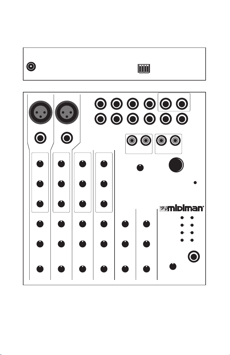
Front & Rear Panels - Fig. 1
Line Gain
Phantom
Line Gain
Phantom
9 VAC
MIC 1
MIC 2
3 mon
5L mon
High
Norm
7L mon
Off
On
12
Channel
9L mon OUT L OUT R
IN 1
1
HIGH
•
•
•
•
-15 +15
MID
•
•
•
•
-15 +15
LOW
•
•
•
•
-15 +15
SEND
•
•
•
•
0 +6
PAN
•
•
L R
GAIN
•
•
•
•
00 +20
IN 2
2 3 4
HIGH
•
•
•
•
•
•
•
•
•
•
•
•
•
•
•
•
•
•
•
•
-15 +15
MID
•
•
•
•
-15 +15
LOW
•
•
•
•
-15 +15
SEND
•
•
•
•
0 +6
PAN
•
•
L R
GAIN
•
•
•
•
00 +20
•
•
•
•
•
•
•
•
•
•
•
•
•
•
•
•
HIGH
•
•
•
•
-15 +15
MID
•
•
•
•
-15 +15
LOW
•
•
•
•
-15 +15
SEND
•
•
•
•
0 +6
PAN
•
•
L R
GAIN
•
•
•
•
00 +20
4 mon
6R str
8R str
LEFT RIGHT
HIGH
•
•
•
•
•
•
•
•
•
•
•
•
•
•
•
•
•
•
•
•
-15 +15
MID
•
•
•
•
-15 +15
LOW
•
•
•
•
-15 +15
SEND
•
•
•
•
0 +6
PAN
•
•
L R
GAIN
•
•
•
•
00 +20
•
•
•
•
•
•
•
•
•
•
•
•
•
•
•
•
TAPE IN
STEREO RTN
•
•
•
•
00 Max
5/6 7/8
SEND
•
•
•
•
•
•
0 +6
BAL
•
L R
GAIN
•
•
•
00 +20
•
•
•
•
•
•
•
•
•
•
00 +20
STR RET SEND10R str
LEFT RIGHT
TAPE OUT
•
•
•
MI IM
XX
10 CHANNEL MIXER
SEND
•
•
•
•
•
•
0 +6
BAL
•
•
L R
GAIN
•
•
•
•
•
MAIN
•
•
•
•
•
•
•
•
00 Max
POWER
10
CLIP
+8
0
- 20
PHONES
TM
Page 5

5
Overview
While reading the following description of how miXim 10 works
it may be helpful to refer to the preceding Front and Rear Panels Figure 1, or the Block Diagram - Figure 3 located in the back of
this manual.
Channel Controls and Inputs
Channels 1 to 4: The miXim 10 has 4 mono inputs (1 through 4)
with gain control, pan control, a mono send and 3 stage EQ.
Channels 1 and 2: Channels 1 and 2 have both XLR and 1/4"
inputs. If a plug is inserted into the 1/4" input of Channels 1 and
2 the XLR is switched out. These inputs can be switched between
high gain, for mics, or low gain, for line level using the corresponding Line Gain dip switches on the back of the unit. Since
the 1/4" inputs on channel 1 and 2 are in parallel with the balanced XLR inputs they can also function as high or low gain
inputs. These 1/4" inputs are somewhat special in that they can
be used as unbalanced inputs by using a mono plug, or as balanced inputs by using a stereo plug.
IMPORTANT: Because channel 1 and 2 are high gain inputs,
we suggest that if you are not using either of these channels
make sure the unused channel’s gain control is turned all the
way down.
XLR Phantom Power: If you are using the XLR inputs on channels
1 and 2 and need to switch phantom power on, you may do so by
using the Phantom power dip switches on the back of the unit.
EQ Controls: The 3 band EQ controls on Channels 1 through 4
offer 15 dB of boost when all the way right and -15 dB of cut when
all the way left. When centered these controls have no effect. The
Low, Mid and High controls act as follows: Low provides shelving below 80 hz; Mid provides peaking centered at 2.5 Khz; and
High provides shelving at 12 Khz.
Page 6

6
Channels 5/6 and 7/8: 5/6 and 7/8 are stereo channels. This
means that the Gain controls on these channels attenuate both of
the respective inputs. When you turn the Balance controls on
these channels all the way to the left you will only get the left
input (5 or 7) going to the left main output. When you turn the
Balance controls on these channels all the way to the right you
will only get the right input (6 or 8) going to the right main output. When these Balance controls are centered you will get left
and right inputs going to both the left and right outputs. The
Send controls on these stereo channels send a mono mix of the
stereo input to the Send out and are unaffected by the Balance
control position.
1/4" Inputs on Channels 5 to 10: These inputs are quite unique.
There are 4 different ways you may use these inputs. If you put a
stereo plug into input 6, 8 or 10 you will get a stereo signal going
to both the left and right main outputs. If you put mono jacks in
both the left (5, 7 or 9) and right (6, 8 or 10) inputs you will get the
left signal going to the left main output and the right signal going
to the right main output. If you put only a mono jack in any of
these left inputs (5, 7 or 9) then this signal will go mono to both
the left and right main outputs. If you put a mono jack in any of
these right inputs (6, 8 or 10) this signal will go mono to only the
right main output.
Channels 9 and 10: Channel 1 through 8 inputs provide up to 20
dB of gain. The remaining two channels (9 and 10)) are unity gain.
Tape In (RCAs): The Tape Left and Right Inputs are summed into
Channel 7/8 and are thus subject to the 7/8 Gain, Balance and
Send Controls.
Send Controls: Channels 1 through 8 on the miXim 10 have individual Send controls. These Send controls provide up to 6 dB of
post-fader gain over the channel's own gain stage. The combined
Send signals are sent out the Send Out at the top right of the unit.
Turning a send pot all the way down will prevent any of that signal from appearing at the send output, while turning it all the
way up will send it to the send output with 6 dB of gain.
Page 7

7
Stereo Return
miXim 10 has a stereo Return. This return is designed to be used
with a tip/ring/sleeve jack. The tip goes left, the ring goes right
and the sleeve is common (ground) to both channels. The Stereo
Return level is controlled by the miXim 10's "Stereo Rtn" pot. If
you are not using the Return, it can be used as additional unity
gain stereo input.
Main Level Pot and LEDs
The Main Level pot simultaneously controls the volume of both
the left and right outputs. The last stage Main amplifier provides up to 20 dB of additional gain. Since clipping doesn’t
occur until approximately +20 dB and the noise floor is at -95
dB, this gives miXim 10 a Signal-to-Noise (S/N) ratio of well
over 100 dB. Because of this, you can run the outputs at the +8
on the Main Level LED Meters (or slightly above) and still have
digital quality signal.
Tape Out (RCAs)
The Tape Left and Right Outs are duplicates of the Main Left and
Right Outs.
Headphone Out
The left and right output signals are also routed to a separate
stereo headphone amplifier. The volume of the headphone output is controlled by the Main volume pot.
Power Indicator Switch
miXim 10 runs on 9 to 12 volts, AC. Whenever miXim 10 is
plugged in and the power switch is pushed in, the Power LED
will light. If the Power LED goes off check to make sure your
wall supply is properly plugged in and that the power switch is
pressed in.
Page 8

8
Typical Set-Up - Fig. 2
Master Keyboard
Master Keyboard
Left Output
Right Output
Speakers
MIDI Sound Module
Microphones
To EQable Ins
MIC 1
IN 1
1
HIGH
•
•
•
•
•
•
•
-15 +15
MID
•
•
•
•
•
•
•
-15 +15
LOW
•
•
•
•
•
•
•
-15 +15
SEND
•
•
•
•
•
•
•
0 +6
PAN
•
•
•
L R
GAIN
•
•
•
•
•
•
•
00 +20
Left
Right
(3 & 4)
MIC 2
IN 2
2 3 4
HIGH
HIGH
•
•
•
•
•
•
•
•
•
•
LOW
•
•
SEND
•
•
0 +6
PAN
•
L R
GAIN
•
•
•
•
•
•
•
-15 +15
MID
MID
•
•
•
•
•
•
•
•
•
•
•
-15 +15
LOW
•
•
•
•
•
•
•
•
•
•
•
-15 +15
SEND
•
•
•
•
•
•
•
•
•
•
•
0 +6
PAN
•
•
•
•
•
L R
GAIN
•
•
•
•
•
•
•
•
•
•
•
00 +20
•
-15 +15
•
-15 +15
•
-15 +15
•
•
00 +20
3 mon
4 mon
HIGH
•
•
•
-15 +15
MID
•
•
•
-15 +15
LOW
•
•
•
-15 +15
SEND
•
•
•
0 +6
PAN
•
L R
GAIN
•
•
•
00 +20
5L mon
6R str
•
•
•
•
•
•
•
•
•
•
•
•
•
•
•
•
•
•
•
•
•
•
Power Amplifier
Left
Left
Right
Stereo
(9 & 10)
7L mon
8R str
LEFT RIGHT
TAPE IN
STEREO RTN
•
•
•
•
00 Max
5/6 7/8
SEND
•
•
•
•
•
•
•
•
0 +6
BAL
•
•
•
L R
GAIN
•
•
•
•
•
•
•
•
00 +20
STR RET
9L mon OUT L OUT R
•
•
•
MIXIM 10
10 CHANNEL MIXER
SEND
•
•
•
•
•
•
0 +6
BAL
•
•
•
L R
GAIN
•
•
•
•
•
•
00 +20
To Unity Gain Ins
Right
Effects Unit
Output Mix
Input
STR RET SEND10R str
LEFT RIGHT
TAPE OUT
POWER
TM
l
CLIP
+8
0
-
20
PHONES
MAIN
•
•
•
•
•
•
•
00 Max
SEND
Left
Right
OUT R
&
OUT L
Headphones
Page 9

9
Setting Up (see "Typical Set-Up" diagram)
When setting up, you should first decide if you are going to need
mic inputs. If you are going to be using mics you need to set the
Line Gain dip switch of the channel you will be using (1 or 2) to
High. If you are going to use one of these channels as a mic in
and the other as a line level in make sure the Line Gain dip
switches on the back of the unit are set accordingly.
IMPORTANT: Because channel 1 and 2 are high gain inputs,
we suggest that if you are not using either of these channels
make sure the unused channel’s gain control is turned all the
way down.
Make sure that the line level instruments that are connected to
inputs 1 through 8 are set to their maximum volume, and control
the mix level from the miXim 10 channel gain pots. Levels of
instruments connected to the unity gain 9 and 10 inputs will have
to be controlled from the individual instruments. If you have a
MIDI volume controllable instrument, you can plug its stereo output into the 9 and 10 inputs and make level adjustments with
your sequencer or MIDI mixing controller.
You will also need to decide how to assign effects and sends. If
you are using miXim 10 for live performance, you may want to
use the send and the stereo return to add stereo effects to your
mix. If you are not using the send to add effects you may use it as
a mono monitor mix. You may also use the headphone out as a
monitor mix. However, it is a stereo output and it doesn't have an
independent volume control.
Setting Up the Outputs
If you are using the miXim 10 in live performance, you will probably want to connect the Left and Right Outs to the input(s) of a
power amplifier. If you are using miXim 10 in a studio application, you will probably plug one output (for mono) or both outputs (for stereo) into one input (for mono) or two inputs (for
stereo) on your mixing board.
Page 10

10
The output levels of miXim 10 are controlled by the stereo Main
level pot. When set to 9 o'clock, miXim 10 has unity gain. This is
the best setting for going into a mixing board. If you are going
into a power amplifier, this pot will act as a convenient volume
control.
Headphones
A headphone amplifier has been built into the miXim 10 to
provide easy monitoring and to allow you to use it quietly at
night (without waking your loved ones or the landlord!). The
headphone jack accurately reflects the signal coming from the
Master Outs. The headphone volume can be adjusted from the
Main level pot.
Applications and Hints
Gain Settings
The gain provided from turning up the Left and Right Level pots
can help drive a power amplifier or boost a signal from -10 to +4
dB signal levels. For unity gain these pots should be set to about
9 o'clock.
For greatest S/N ratio, Master Levels should be run as close to
clipping as possible. When mixing a number of keyboards or
modules, the level of the instrument with the lowest output
should be set first by adjusting its gain to just below clipping.
Gain controls for the other channels can then be adjusted to
achieve the desired mix.
Don’t be afraid of the yellow Master Level LEDs (+8 dB). For the
best results, the yellow LEDs should be lit most of the time.
Using the Send and Return for Effects
Channels 1 through 8 of the miXim 10 have a Send control. This
send can be used for several things, the most common of which is
to add effects such as reverb or delay to an instrument that has no
built-in effects.
The miXim 10 also has a stereo effects return. The stereo return
Page 11

11
enables you to incorporate stereo effects in your mix. If you need
more than one stereo return, use two of the regular channel
inputs. This technique also enables you to adjust the placement of
the effect in the stereo field by adjusting the pan pots on the channels to which you have routed the effects unit.
For the best S/N ratio, set the send level on the miXim 10 so that
the effects unit is getting the “hottest” possible signal without
overloading. Set the effects unit to output wet (processed) signal
only and use the miXim 10's return level to control the mix of
processed and non-processed signal.
Block Diagram - Fig. 3
CHANNELS 1 and 2
XLR
GAIN
PAN
EQ
LEFT BUS
1/4"
GAIN
SWITCH
CHANNELS 3 and 4
GAIN
CHANNELS
5 & 7
GAIN
CHANNELS
6 & 8
RIGHT BUS
SEND
PAN
EQ
SEND
BALANCE
LEDs
SEND
LEFT
LEDs
RIGHT
PHONES
OUT
LEFT
MAIN
OUT
RIGHT
PHONES
OUT
RIGHT
MAIN
OUT
LEFT
SEND
9 IN
10 IN
STEREO
RETURN
MAIN
Page 12

12
Limited Lifetime Warranty
MIDIMAN warrants that this product is free of defects in materials and
workmanship under normal use so long as the product is owned by the
original purchaser and that purchaser has registered his/her ownership
of the product by sending in the completed warranty card.
In the event that MIDIMAN receives written notice of defects in materials or workmanship from such an original purchaser, MIDIMAN will
either replace the product, repair the product, or refund the purchase
price at its option. In the event any repair is required, shipment to and
from MIDIMAN and a nominal handling charge shall be born by the
purchaser. In the event that repair is required, a Return Authorization
number must be obtained from MIDIMAN. After this number is
obtained, the unit should be shipped back to MIDIMAN in a protective
package with a description of the problem and the Return Authorization
clearly written on the package.
In the event that MIDIMAN determines that the product requires repair
because of user misuse or regular wear, it will assess a fair repair or
replacement fee. The customer will have the option to pay this fee and
have the unit repaired and returned, or not pay this fee and have the
unit returned unrepaired.
The remedy for breach of this limited warranty shall not include any
other damages. MIDIMAN will not be liable for consequential, special,
indirect, or similar damages or claims including loss of profit or any
other commercial, damage, even if its agents have been advised of the
possibility of such damages, and in no event will MIDIMAN’s liability
for any damages to the purchaser or any other person exceed the price
paid for the product, regardless of any form of the claim.
MIDIMAN specifically disclaims all other warranties, expressed or
implied. Specifically, MIDIMAN makes no warranty that the product is
fit for any particular purpose.
This warranty shall be construed, interpreted and governed by the laws
of the state of California. If any provision of this warranty is found void,
invalid or unenforceable, it will not affect the validity of the balance of
the warranty, which shall remain valid and enforceable according to its
terms. In the event any remedy hereunder is determined to have failed
of its essential purpose, all limitations of liability and exclusion of damages set forth herein shall remain in full force and effect.
 Loading...