

Page 1

Page 2

Contents
Microphone Design . . . . . . . . . . . . . . . . . . . . . . . . . . . . . . . . . . . . . . . . . . . . . . . . . . . . . . . . . . . .3
Microphone Types . . . . . . . . . . . . . . . . . . . . . . . . . . . . . . . . . . . . . . . . . . . . . . . . . . . . . . . . .3
Capsule Size . . . . . . . . . . . . . . . . . . . . . . . . . . . . . . . . . . . . . . . . . . . . . . . . . . . . . . . . . . . . . .4
The Backplate . . . . . . . . . . . . . . . . . . . . . . . . . . . . . . . . . . . . . . . . . . . . . . . . . . . . . . . . . . . .5
Patterns . . . . . . . . . . . . . . . . . . . . . . . . . . . . . . . . . . . . . . . . . . . . . . . . . . . . . . . . . . . . . . . . .6
Top Address vs. Side Address Designs . . . . . . . . . . . . . . . . . . . . . . . . . . . . . . . . . . . . . . . . .8
Microphone Electronics . . . . . . . . . . . . . . . . . . . . . . . . . . . . . . . . . . . . . . . . . . . . . . . . . . . .8
Manufacturing Standards . . . . . . . . . . . . . . . . . . . . . . . . . . . . . . . . . . . . . . . . . . . . . . . . . . .10
Caring for Microphones . . . . . . . . . . . . . . . . . . . . . . . . . . . . . . . . . . . . . . . . . . . . . . . . . . . . . . .13
Shock Protection . . . . . . . . . . . . . . . . . . . . . . . . . . . . . . . . . . . . . . . . . . . . . . . . . . . . . . . . .13
Pop Filters and Windscreens . . . . . . . . . . . . . . . . . . . . . . . . . . . . . . . . . . . . . . . . . . . . . . . .13
Temperature and Humidity . . . . . . . . . . . . . . . . . . . . . . . . . . . . . . . . . . . . . . . . . . . . . . . . .13
Cleaning and Storage . . . . . . . . . . . . . . . . . . . . . . . . . . . . . . . . . . . . . . . . . . . . . . . . . . . . . .14
Basic Miking Concepts . . . . . . . . . . . . . . . . . . . . . . . . . . . . . . . . . . . . . . . . . . . . . . . . . . . . . . . .15
Close-Miking vs. Distance-Miking Techniques . . . . . . . . . . . . . . . . . . . . . . . . . . . . . . . . . . .15
Large Capsules vs. Medium Capsules . . . . . . . . . . . . . . . . . . . . . . . . . . . . . . . . . . . . . . . . .16
Dealing with Unwanted Low-Frequencies . . . . . . . . . . . . . . . . . . . . . . . . . . . . . . . . . . . . .16
The Mic Preamp . . . . . . . . . . . . . . . . . . . . . . . . . . . . . . . . . . . . . . . . . . . . . . . . . . . . . . . . .16
The Recording Environment . . . . . . . . . . . . . . . . . . . . . . . . . . . . . . . . . . . . . . . . . . . . . . . .17
Phasing Issues with Multiple Microphones . . . . . . . . . . . . . . . . . . . . . . . . . . . . . . . . . . . . .18
Stereo Miking Techniques . . . . . . . . . . . . . . . . . . . . . . . . . . . . . . . . . . . . . . . . . . . . . . . . . . . . . .21
X-Y . . . . . . . . . . . . . . . . . . . . . . . . . . . . . . . . . . . . . . . . . . . . . . . . . . . . . . . . . . . . . . . . . . . .21
Blumlein . . . . . . . . . . . . . . . . . . . . . . . . . . . . . . . . . . . . . . . . . . . . . . . . . . . . . . . . . . . . . . . .22
ORTF . . . . . . . . . . . . . . . . . . . . . . . . . . . . . . . . . . . . . . . . . . . . . . . . . . . . . . . . . . . . . . . . . .22
Mid-Side . . . . . . . . . . . . . . . . . . . . . . . . . . . . . . . . . . . . . . . . . . . . . . . . . . . . . . . . . . . . . . . .22
Spaced Omni . . . . . . . . . . . . . . . . . . . . . . . . . . . . . . . . . . . . . . . . . . . . . . . . . . . . . . . . . . . .23
Decca Tree . . . . . . . . . . . . . . . . . . . . . . . . . . . . . . . . . . . . . . . . . . . . . . . . . . . . . . . . . . . . . .23
Specific Miking Applications . . . . . . . . . . . . . . . . . . . . . . . . . . . . . . . . . . . . . . . . . . . . . . . . . . . . .25
Vocals . . . . . . . . . . . . . . . . . . . . . . . . . . . . . . . . . . . . . . . . . . . . . . . . . . . . . . . . . . . . . . . . . .25
Acoustic Guitar . . . . . . . . . . . . . . . . . . . . . . . . . . . . . . . . . . . . . . . . . . . . . . . . . . . . . . . . . .26
Electric Guitar . . . . . . . . . . . . . . . . . . . . . . . . . . . . . . . . . . . . . . . . . . . . . . . . . . . . . . . . . . .27
Grand Piano . . . . . . . . . . . . . . . . . . . . . . . . . . . . . . . . . . . . . . . . . . . . . . . . . . . . . . . . . . . . .27
Drums . . . . . . . . . . . . . . . . . . . . . . . . . . . . . . . . . . . . . . . . . . . . . . . . . . . . . . . . . . . . . . . . .28
The M-Audio Family of Microphones . . . . . . . . . . . . . . . . . . . . . . . . . . . . . . . . . . . . . . . . . . . . .33
. . . . . . . . . . . . . . . . . . . . . . . . . . . . . . . . . . . . . . . . . . . . . . . . . . . . . . . . . .
oubleshooting
r
T
Contact Information . . . . . . . . . . . . . . . . . . . . . . . . . . . . . . . . . . . . . . . . . . . . . . . . . . . . . . . . . .35
Tips
34
Page 3
Chapter 1
output signal
voltage
coil
fixed magnet
+
-
diaphragm
output signal
voltage
coil
fixed magnet
+
-
metal ribbon diaphragm
fixed magnet
output signal voltage
+
-
diaphragm
Choosing & Using Microphones
Microphone Design
While all micr
ophones are designed for the common purpose of converting variations in sound
pressure to electronic signals, different technologies have their benefits depending upon the
a
pplication.This chapter examines the merits of different design types, capsule sizes, polar patterns,
electronics and more.
Microphone Types
The three main types of microphones in common use today are dynamic, ribbon and condenser.
Each has unique attributes appropriate for different applications.
Dynamic microphones
The dynamic or moving-coil microphone is the easiest to understand. It is the classic technology
taught in grade school as the inverse of the common speaker. A plastic or metal diaphragm is
attached to a copper coil that is, in turn, suspended in a magnetic field.Sound pressure waves hitting
the diaphragm cause it to move, and with it, the coil within the magnetic field. The resulting
magnetic fluctuations translate to electrical fluctuations
generally corresponding to the physical fluctuations of the
original sound wave.
Due to the requirement of attaching the coil directly to the
diaphragm, dynamic diaphragms are thicker and, therefore, less
sensitive than the ribbon and condenser microphones
discussed shortly.These same design considerations also give
the ability to take the greatest amount of sound pressure
before distorting, as well as the greatest amount of physical
abuse. Dynamics are also the easiest and least expensive to
make. Dynamics also to tend to color the sound in the range of
about 5k to 10k, and start to sound thinner when more than
about a foot away from the source.
In dynamic mics, sound pressure moving the
diaphragm causes the attached voice coil to interact
with a magnetic field to produce an electric signal
For these reasons, dynamic mics are most often found in
the average stage situation. After all, live performance
environments are much more likely to subject mics to
torture such as high volume, sweat, the elements, shock
and being dropped. In the studio, dynamic mics are most
often used to close-mic drums due to the possibility of
wayward drum sticks. Large-diaphragm dynamics are often
used on kick drums due to high sound pressure levels and
low-frequency content.
Ribbon microphones
Ribbon mics are another form of dynamic microphone distinct from the moving-coil variety. A very
thin metal ribbon suspended between the poles of a powerful magnet moves in response to sound
waves, thus cutting through the magnetic field and inducing a flow of electrons. The resulting
low-voltage output is typically fed to a step-up transformer and sent down the mic cable. The
extreme thinness of the ribbon makes this type of mic the most sensitive, especially at very low
sound levels.They are most often used in close-miking situations and, because they are also the
most fragile and costly mic design, ribbons are typically reserved for very controlled conditions.
Like moving-coil dynamics, ribbon mics color the sound in a way that is often employed to warm
up brassy sounds. (Ribbons are a great choice for recording sax, for example.) They also tend to
In ribbon mics, sound waves cause a thin metal
ribbon to mov
e within a magnetic field to produce
a current
3
Page 4

have very low output, thereby requiring more electronic gaina factor that necessitates
small capsule
medium capsule
large capsule
20 20k10k 15k1k
20 20k10k 15k
1k
20 20k10k 15k1k
ultra -thin diaphragm
solid backplate
capacitance
output
signal
Choosing & Using Microphones
high
-quality preamp electronics in order to avoid noise.
Condenser microphones
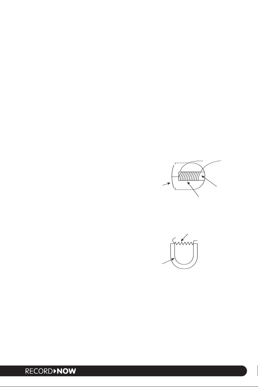
Condenser mics are the most common for studio use. A thin
electrically conductive diaphragm is suspended over a back plate,
forming a delicate flexible capacitor.When sound waves excite the
diaphragm, the distance between the diaphragm and back plate
changesand with it the capacitance. This capacitance change, in
turn, produces a voltage change. Associated circuitry converts
these variations in voltage to a signal that is sent to the preamp.
The power required by this design is serviced by the 48-volt
phantom power commonly found on preamps and mixer inputs.
The diaphragms of condenser microphones are made of extremely thin metal or metalized plastic
similar in thickness to kitchen plastic wrap.Their thinness makes condenser mics very accurate in
frequency response and extremely sensitive to transients, such as the initial crack of a drum being
struck. In addition to imparting the least sonic coloration of any microphone design, the sensitivity
of condensers extends much further from the source than other mics, thus allowing greater
flexibility.This greater sensitivity also provides the engineer with the option of picking up more the
room ambiencea factor that can add a great deal of realism to a recording.
Condensers are more delicate than moving-coil dynamics, yet much more resilient than ribbons.
Due to sensitivity to low-frequency handling noise and the delicacy of the diaphragm, condensers
are invariably used in conjunction with a shock mount, and often with the addition of a pop filter.
The sonic characteristics of condensers and the need for TLC make them more ideally suited for
studio recording. That is not to say that condensers cant be used for so me tas ks on stage
just that the environment should be controlled, such as in a professional show where cables
are secured, mics are shock-mounted against vibration, and the stage is restricted to
professional personnel.
In condenser mics, sound waves hitting
the diaphragm change the capacitance
in the field between the charged
diaphragm and backplate
Since condenser construction technology is much more labor-intensive and sophisticated
compared to that of dynamics, good quality condensers tend to cost comparatively more money.
Condensers are excellent choices for miking vocals, acoustic guitar, piano, orchestral instruments,
saxophone, percussion and sound effects.As condensers are the predominant type of microphone
for studio use, this guide will focus on condenser applications.
Capsule Size
The capsule incorporates the all-important diaphragm
assembly that translates sound pressure into an electric
signal. Condenser capsules come in three basi c sizes
small, medium and large. Generally speaking, frequency
response is a function of diaphragm size. Consider what
happens with speakers of different size. As woofers get
larger, they become more efficient at producing low
frequencies and less efficient at producing high frequencies.
In general, the same is true as the diameters of diaphragms
ease (with some ca
incr
Signal-to-noise ratio of the micr
more surface area that a diaphragm has, the greater its potential sensitivity to sound pressure and
onger the output signal.
the str
signa-to-noise ratios than do small ones.
veats well cover in a minute).
ophone as a whole generall
large dia
esult,
As a r
Without intervention, microphones tend to be
less linear as the diaphragm size increases
es in par
w
y o
phragms inher
t to diaphragm size.The
y exhibit m
entl
uch better
4
Page 5
Small Capsules
patented Disk Resonator boosts
high frequencies for full
frequency response
backplate
sound waves
3-micron evaporated gold
diaphragm
Choosing & Using Microphones
Small capsules ar
e typically those with diaphragm diameters of less than about 1/2. Categorically,
they are extremely accurate through the audible range of 20Hz to 20kHz. Their poor signal-tonoise ratio
, however, requires tricks with electronics and relegates small capsules to being most
useful for measurement rather than recording.
Medium Capsules
Medium capsules have diaphragms that are approximately 1/2 inch to 3/4 inch in diameter. Given
the right design and manufacturing, they typically exhibit flat frequency response from about 20 to
18k. Their diaphragms are also large enough to deliver signal-to-noise ratios acceptable for
professional use.
Large Capsules
Large capsules have diaphragms measuring 3/4 inch to one inch or even greater. Since larger
diaphragms yield better signal-to-noise ratios and greater sensitivity without having to induce
additional gain stages, bigger is typically considered better. Large capsules also tend to produce
greater low frequency detaila quality that cant be measured so much as heard. Large capsules
exhibit a proximity effect (most predominantly in the cardioid polar pattern), meaning that they
tend to sound more boomy as they get closer to the source. Large diaphragm M-Audio mics
include the Solaris, Luna and Nova.
The Diaphragm
The diaphragm is a critical component because it is
responsible for responding directly to sound waves. The
sensitivity of a mic is partially related to the thinness of its
diaphragm. (Recall that the comparatively thin diaphragm of
a condenser is largely what makes this type of mic much
more linear and sensitive to detail than a dynamic
moving-coil mic.)
Originally, condenser diaphragms were made from very thin, light metal such as nickel. As
technology evolved, it became possible to use synthetic materials such as mylar in order to create
tissue-thin membranes. Since condenser diaphragms need to conduct electricity, these synthetic
materials have a thin layer of gold applied to themthe thinner, the better. Most modern
condenser diaphragms are 6 to 12 microns in thickness. (A human hair is 40 microns in diameter.)
The M-Audio large capsule mic, the Solaris, employs a special ultra-thin 3-micron, highly resilient
mylar diaphragm. This delivers a degree of sensitivity unparalleled in the industry. (Physics dictates
that we employ 6-micron diaphragms in our Luna and Nova models.)
In the old days, manufacturers would apply the gold to the diaphragm using a process known as
sputtering.They would place the diaphragm substrate in a vacuum jar, atomize the gold, and then
blow the gold onto one side of the material.Todays vacuum chambers are far superior, allowing us
to use a refined technique where we place our ultra-thin mylar film in a complete vacuum and
evaporate the gold in such a way that it adheres uniformly to the mylar.The result is a diaphragm
that is we feel is the most sensitive in the industry.
Condenser diaphragms can be extremely sensitive to humidity and temperature changes. In order
to minimize that, we temper our diaphragms by baking them for specific times at specific
temperatures in order to insure maximum stability and performance.
The Backplate
In a condenser mic, the diaphragm is suspended over a backplate that carries one half of the
electrical charge that r
microphones were made of solid brass.In an effort to cut costs, most modern manufacturers make
the backplate out of injection-molded plastic and metalize them in some wa
esults in the ca
pacitance
The backplates of the best classic condenser
.
Critical listeners
.
y
5
Page 6
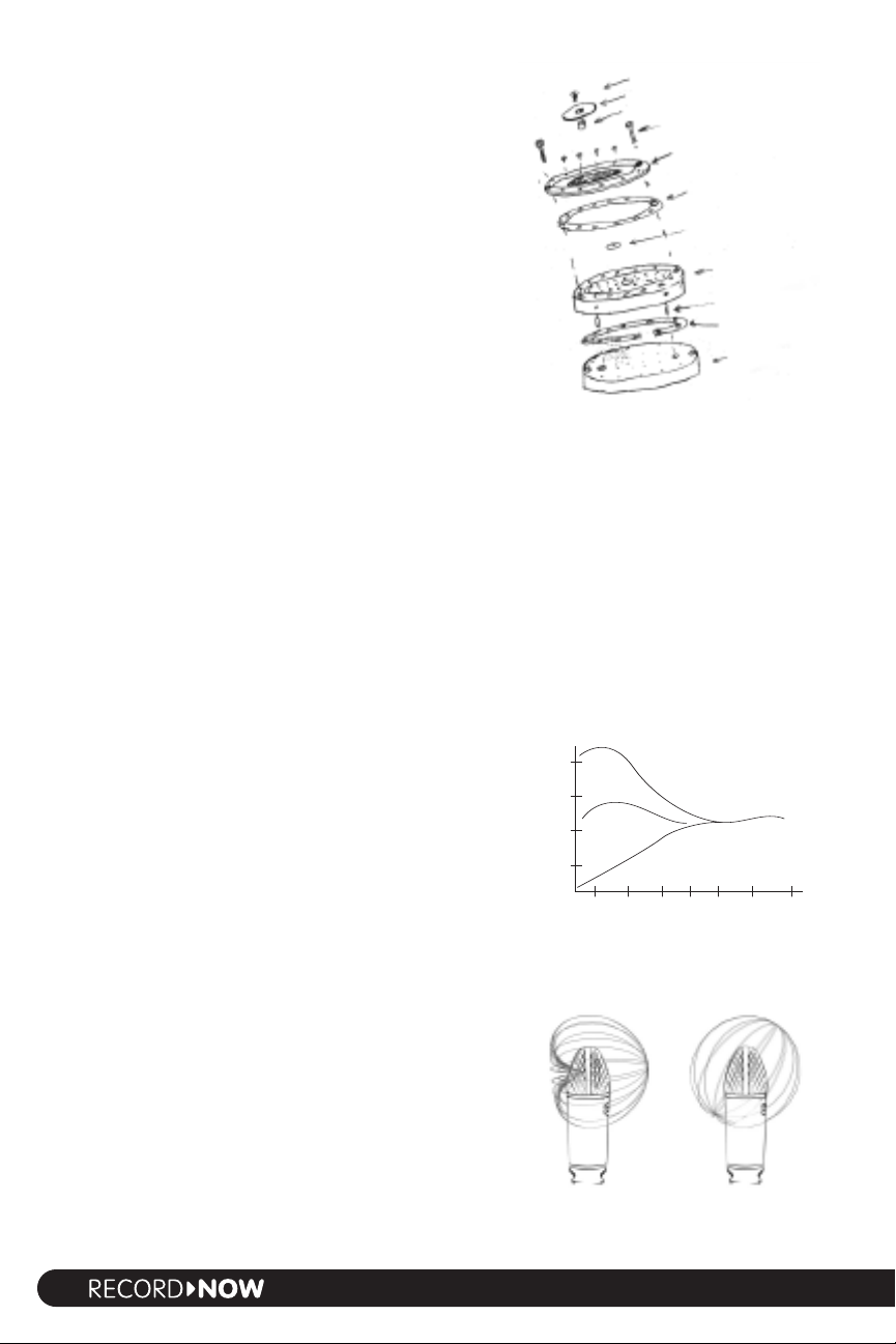
invariably prefer the sound of solid brass. Needless to say,
screw/contact
resonator disk
disk spacer
backplate screws
diaphragm
w/ mounting ring
ring spacer
center spacer
backplate
registration pins
backplate spacer
backplate base
Choosing & Using Microphones
30 cm (1')
7.5 cm (3")
0.6 cm (1/4")
10
5
0
-5
--10
50 100 200 500 1k 2k 5k 10k
Frequency (Hz)
Relative level (dB)
w
e use solid brass backplates in all M-Audio mics.
The spacing betw
een the diaphragm and backplate is
critical. In order to avoid problems with barometric
pressure, the spacer ring has a break in order to allow air
to move freely between these two components. We
precision drill approximately 100 extremely fine holes in
the backplate, some going all the way through and some
only going partially through. This combination further
allows the appropriate amount of damping for the
diaphragm.We then lap the surface in order to ensure that
it is completely flat.This operation requires such precision
that we measure the results not with a ruler, but with
reflected light.
This level of precision is only possible due to modern
computer-controlled manufacturing techniques. The
important distinction is that these operations are
The major components of a large M-Audio condenser
capsule are a solid brass backplate and an ultra-thin
evaporated gold diaphragm
programmed and supervised by human technicians at
every step. All-in-all, there are several hundred precision operations that go into making each of
our solid-brass capsules.Thats more than the number involved the crafting of the average Martin
gu ita ran d were talking about something the size of a 50-cent piece.
Patterns
The term polar pattern is used to describe the response of a microphone to sound sources from
various directions. Each type of polar pattern has its own place and usage in the recording process.
Note that the classic polar pattern definitions apply most accurately when sounds hit the
microphone on axisthat is to say, approaching perpendicular to the planar surface of the
diaphragm. In general, microphones tend to become more directional in focus as frequencies
increase. Put another way, capsules are generally less sensitive to high frequencies off axis. This
phenomenon is typically less significant in medium capsules than in large capsules.
Cardioid pattern
The cardioid is the most common polar pattern found in
microphones. The name derives from this patterns
resemblance to a heart shape. Cardioids are unidirectional,
meaning that they pick up sound primarily from the front
of the capsule. The back of the capsule rejects sound,
allowing the engineer to isolate the signal source from
other performance elements or background noise. More
noticeable in larger capsule designs, cardioid patterns
typically exhibit a
proximity effecta boost in low-mid
frequencies as the proximity between the source and mic
increases. Proximity effect is also more prominent with
both larger capsules and lower frequencies.
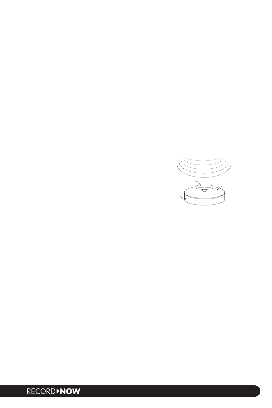
Omni pattern
As the name implies, the omni-directional, or omni pattern,
picks up sounds equall
used to ca
thereby yielding a more open sound compared to the more
ocused quality of car
f
Foley sound effects, and realistic acoustic instruments
assuming that acoustic space of the r
is desirable.
pture room resonance along with the source,
dioid.
y w
ell fr
om all dir
ections.
Omni is great for vocal groups,
ding en
ecor
Omni is
onment
vir
The proximity effect causes increased output in
the low-mids as distances between the mic and
Cardoid patterns are most
sensitive on the side of
the capsule
source increase
Omni patterns are
sensitive to sound from all
directions
6
Page 7
Omni also exhibits significantly less proximity effect than cardioids. One result is that omnis are
Choosing & Using Microphones
+
=
-
=
-
=
30dB
30dB
20dB
10dB
0dB
10dB
2
0dB
1
20
90
60
30
0
330
300
270
240
210
180
150
100 Hz 1 kHz 10 kHz
some
what less sensitive to the movements of an animated vocalist. Another is that omnis tend to
have less need for EQ. As mentioned earlier,while omnis pick up 360 degrees of sound, they tend
to be mor
e directional as frequencies increase espec ially in larger capsules.
Figure 8 or bidirectional pattern
The figure 8 or bidirectional pattern is equally sensitive on the two opposing faces of the
microphone, yet rejects sound from the sides.This pattern does exhibit the proximity effect found
in cardioid patterns.
The figure 8 is excellent for capturing a duet or face-to-face
interviews with a single mic. The —40dB side rejection spec
also makes it great for isolating an instrument like a snare
from the rest of the drum kit.Figure 8 is also one of the key
components of M/S (mid-side) mikingan advanced stereo
recording technique well look at little later.
Super-cardioid pattern
The super-cardioid pattern exhibits an even narrower area of
sensitivity than the classic cardioid and is used for very
sonically focused recording. Super-cardioid is great for
zeroing in on that perfect sweet spot for instruments such
as piano or drum.This pattern is also ideal for live recording
sessions where isolation is important, including minimizing
bleed between a vocalist and their own instrument.
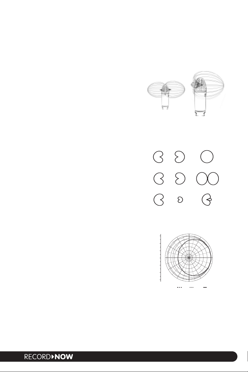
Single pattern vs. multi-pattern mics
The most inexpensive way to make a microphone is with a
single fixed pattern. Cardioids have openings in the backs of
the capsules that produce the physics of a unidirectional
pattern.This is an inherently fixed pattern design.An omnidirectional pickup pattern can be achieved by sealing the
back of the capsule, resulting in another fixed pattern.
Super-cardioids employ yet a different design. In most cases,
different back-end electronics are required for each pattern,
thus making it difficult to make interchangeable capsules.
The secret to building a single mic with multiple pickup
patterns is placing two cardioids back-to-back in
combination with various electronic tricks. An omnidirectional pattern occurs as the result of wiring two backto-back cardioids in phase with each other. Similarly, those
same two opposing cardioids wired out of phase yield a
figure 8 or bi-directional pattern*. Tweaks to the polarity
and output level result in a super-cardioid pattern. While
the presence of two high-quality diaphragm/backplate
assemblies incr
eases the cost, this solution provides the
best polar pattern performance and is still significantly less
expensive than buying multiple microphones in order to
have a choice of patterns at your disposal.
Figure 8 patterns are
sensitive on opposing sides
and exhibit strong rejection
at 90 degr
ees off axis
In multi-pattern microphones, two cardioids combine
in different ways to create other patterns
All microphones are less sensitive to high
frequencies off axis (omni example shown)
The super-cardioid
pattern has an even
greater focus of sensitivity
than cardioid
This approach to capsule design can be seen in the M-Audio Solaris. The Solaris employs an
opposing pair of the same diaphragm/backplate assemblies, thus allowing for the selection of
ultiple patterns via s
m
*Tip:
uninitiated. One side will sound strange to a vocalist or speaker who is simultaneously monitoring the mic
witches on the body of the mics.
Note that the out-of-phase wir
ing of the two sides of a f
e 8 capsule can play tr
igur
icks on the
7
Page 8
signal through headphones.That’s because one side of the mic is in phase with the performer (and therefore
top address
side address
Choosing & Using Microphones
reinforcing their perception of their own sound) while the other side is not. Addressing the in-phase side
while monitoring produces optimal monitoring results.
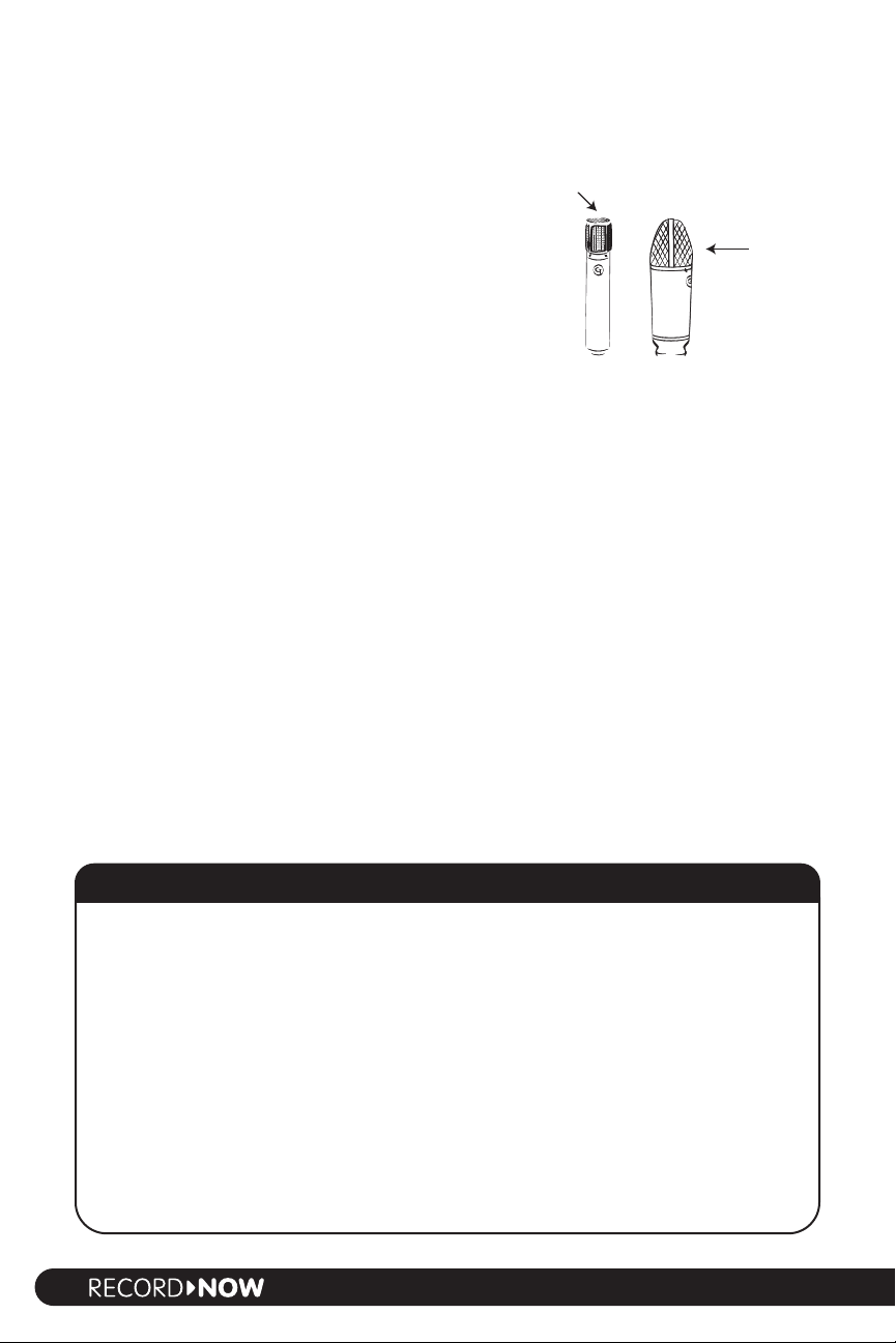
Top Address vs. Side Address Designs
The orientation of the diaphragm within the head of the
microphone determines if the microphone is addressed
from the top or the side. While not an absolute rule,
medium diaphragms are typically top-address while large
diaphragms are usually side-address. As you might
surmise from the previous discussion about design
considerations in attaining various polar patterns,
top-address mics typically have single pattern (at least
without physically changing the capsule) while sideaddress mics lend themselves to the possibility of back-toback capsules for switchable patterns. Note that on side-
Side addr
ess and top address
microphone designs
address mics, the side with the logo is usually the primary
or cardioid side.
Polar patterns aside, the practicality of side-address versus top-address designs also has to do with
logistics. Top-address microphones can usually fit into tighter spots than can side-address mics
(between drums, for example).This is yet another reason why pro engineers keep a variety of mics
in their arsenal.
Microphone Electronics
As weve seen, the microphone capsule is responsible for translating sound waves into electrical
signals. The other important part of the microphone is the head amp that conditions the sound
coming from the capsule so that it can be transmitted through a length of cable to an external
preamp or console.
Part of a head amps job is impedance conversion. (See A Word About Impedance for more
information on impedance.) The average line-matching transformer found in dynamic or ribbon
microphones has to convert on the order of several thousand ohms down to around 200 ohms
(or from half an ohm up to about 200 ohms).The condenser microphone presents a challenge of
a different magnitudeconverting a signal in the range of two billion ohms down to 200 ohms.This
incredible leap is beyond the scope of most output transformers, requiring the addition of a
specialized amplifier.
Impedance essentially describes the resistance in a circuit.Water flowing through a pipe is a good analogy to electrons
flowing through a wire. Lets say youve got a pump designed to put 100 pounds of pressure into an eight-inch pipe. If you
double the size of the pipe to 16 inches, you get half the pressure.While the pressure is now only 50 lbs,there is no damage
to the system. Halving the size of the pipe, on the other hand,yields twice the pressure that the system was designed for.
As a result, back-pressure affects the pump, further reducing its efficiency and increasing the potential of an explosion.
In terms of audio electronics, the pipe scenario is analagous to inputting the output from a 100-watt amp into 8-ohm
While using 16
ers.
speak
almost certainly blow up the amp.Thats why guitar amps designed to run into different speaker ratings often have
output transformers with 4-, 8- and 16-ohm taps which appropriately condition the output signal.
Guitar pickups and most dynamic mics are considered to be high impedance, meaning that they exhibit an
impedance of many thousands of ohms. Low-impedance signals are generally around 200 ohms or less.While the
high-impedance signals typically exhibit greater voltage, they can only be run through about 20 feet of cable before
they begin to lose high frequencies (or require additonal amplification in order not to). Low-impedance signals can
y be run m
typicall
-
uch fur
A Word About Impedance
ohm speak
ers is safe (though it reduces output power), switching to 4-ohm speakers will
ther without detriment.
8
Page 9

An output transformer and/or amplifier serves as a sort of translator and, in audio, we expect that
Choosing & Using Microphones
translation to be excellent in or
signal-to-noise ratio. Just as a professional language translator costs more than someone who just
took a f
ew years of foreign language in high-school, pro-quality output transformers and amplifiers
cost more than garden-variety ones. (A single transformer like those used in each channel of pro
consoles and outboard preamps can cost more than a complete inexpensive multi-channel mixer.)
Because the quality of this formidable translation is so critical in a professional-quality microphone,
all M-Audio mics employ high-quality Class A electronics in the head amp.
Tubes vs. solid state
The head amp can employ either tube electronics or less expensive solid state electronics. Before
we can effectively compare these two technologies, it is important to understand some
fundamental concepts.There are three main ways to measure how accurately an electronic circuit
passes soundfrequency response, total harmonic distortion (THD), and dynamic distortion.
Frequency response is the simplest to understand.Were simply talking about whether any highs or
lows are rolled off, or if any frequencies are cut or boosted to exhibit a non-linear frequency
response. Both tube and solid state electronics can be made without significant deficiencies in
frequency response.
Regarding THD,all electronics induce some kind of harmonic distortion, i.e. harmonics that are not
present in the original source. The nature of the harmonic distortion has more to do with the
associated circuitry than with tubes versus solid state.
components handle the entire signal waveform) tends to produce lower-order harmonics. On the
other hand,
separate devices) tend to produce higher-order harmonics. For this reason, Class A strikes most
people as sounding warmer. (All M-Audio mics employ Class A circuitry.)
That brings us to the third, more mysterious element called dynamic distortionsomething that
the industry didnt even have the technology to measure until quite recently. Dynamic distortion
refers to the accuracy or transparency over time,particularly critical regarding the transient at the
very beginning of a sound.Take the recording of a finger snap,for example.You can roll off the highs
and lows and/or introduce a good amount of distortion, yet still perceive the sound as a snapping
finger. Change the dynamic, however, and that snap can quickly lose its characteristic snap. In
general, accuracy in reproducing dynamics can make the difference between something sounding
full and three-dimensional or flat and two-dimensional.
Class B (where the positive and negative parts of the waveform are amplified by two
der to maintain frequency response, dynamic range, and
Class A circuitry (where all amplifying
Ironically, the discussion comes down to measuring things that dont matter and not measuring
things that do.Tubes measure greater in THD than solid state.While one can measure the difference
between .01 percent THD and .001 percent THD, its practically impossible to hear that difference.
On the other hand, while its difficult to measure dynamic distortion you can definitely hear it. Solid
state electronics exhibit many orders of magnitude more dynamic distortion than tubes.This is a
major reason why tube mics make recordings sound truer to life.
Tube electronics
Tubes cost more money to manufacture than comparable solid state electronic components. In fact,the
music industry is one of the few places where tubes have value in the face of more modern electronics.
Its a known fact that the average tube exhibits more inherent noise than solid state electronics. In
general, the smaller the tube, the better. Larger tubes have a greater propensity for being
microphonic, i.e. generating noise from mechanical movement of the internal parts. They also use
higher voltages that result in more heatand subsequently more noise. Most manufacturers tube
mics employ larger 12-volt tubes like the 12AX7an older tube design that is noisier when used
in microphone design.
TIP: One of the first things to be aware of is that not all products advertised as being tube mics employ
tubes in the main signal path.
a tube in the side-chain. (You can literally cut the tube out of the circuit on some models and the mic will
Some popular lo
w-cost mics utiliz
e less expensive solid-state circuitr
, putting
y
9
Page 10

still work.) The theory there is that the tube is used as a sort of processor to “warm” up the sound.The
Choosing & Using Microphones
reality is that these are still solid state mics masquerading as tube mics as cheaply as possible.
Because of the ph
ysics behind tube operation, tube mics have classically been subject to certain
physical restriction on the length of the cable between the microphone and power supply. As a
result, tube mics are normally restricted to cable lengths of about 15 feet. This has sometimes
required the use of solid state mics in scenarios such as drum overheads, remote recording or
orchestral recording.
Solid state electronics
Solid state microphones cost significantly less to manufacture than tube mics. As such, they are
found in the less expensive condenser mics on the market. (As stated earlier, some manufacturers
put low-quality tubes in their solid state mics like an effects circuit in order to advertise products
as being tube mics.)
In most solid state condensers, the key components are a series of op amps. All M-Audio mics employ FETs
(field effect transistors) instead. Logic says that op amps should be preferable because they have lower
measured amounts of THD. As discussed previously, while that difference in THD specs is measurable it is not
audible in well-executed microphone applications. Op amps, however, can have much more dynamic distortion
than FETssomething you can hear. Moreover, many designs use multiple op amps to do the job of one FET.
The difference is so profound that many people think that our solid state mics sound like most manufacturers
tube mics.
The Myth of Tube Warmth
There is a common myth that tubes are warmer sounding. It certainly can be said that cranking up a
tube amp will make an electric guitar sound warm, fat or distorted. That scenario, however, is one
in which distortion is desirable. On the other hand, distortion is the enemy of the engineer who is
attempting to record a sound source faithfully and realistically. Here, you want accuracy and transparency
rather than any coloration that might be described subjectively with a word like warmth. Fortunately,
there are many types of tubes and related circuitry that result in comparatively transparent sound.
It has also been said that tubes warm up digital recordings.This implies that there is something inherently
deficient in digital recording.While some purists will always make a case for analog over digital, the fact
is that a vast number of todays pro recordings are made with digital technology such as M-Audios
24-bit/96k Delta cards, USB and FireWire solutions.
Digital recording significantly increased the dynamic range, allowing us to better hear the dynamics of
recorded material. As a result, people were quick to label digital recording as cold, when using solid
state mics. When using a tube mic, everything suddenly sounded warmer by comparison. In actuality,
digital recording simply gave us the means of hearing differences we didnt hear before (such as how tube
output is dynamically truer than solid state).
Manufacturing Standards
e are quite a number of condenser microphones to choose from on the market today. Many
Ther
look pr
is that most companies engineer for profit.This guide was designed to help you think about whats
inside those shin
The story behind affordable matched pairs for stereo-miking
One of the factors that make a significant difference between amateur and professional recordings
is the use of stereo miking techniques. Pro engineers have long relied on matched pairs of
microphones to attain optimal results from stereo recording methods. Why a matched pair? You
wouldnt consider monitoring with a mismatched pair of speakers, right? Similarly, you want the left
and right mics hearing exactly the same way in order to achieve a balanced sound.
essional on the outside and, indeed, most will give you acceptable sound. However,the fact
of
y casesand m
uch of that comes do
wn to man
ufacturing standar
ds.
10
Page 11

From a technical perspective, the two mics need to be as identical as possible in frequency
Choosing & Using Microphones
r
esponse. A flat frequency response implies that there is no deviation in the output level versus
the input level at any and all frequencies across the audible spectrum. While a flat frequency
r
esponse is theoretically ideal, it is rarely achieved completely in any audio component. For
example, a mic might exhibit a 1dB boost at 1kHz and start rolling off 3dB per octave at 14kHz.A
perfectly matched pair would exhibit the same exact characteristics in both mics. Here again, such
an exacting match is rare.Therefore manufacturers each establish their own window of acceptable
deviation that they will certify as a being a matc hed p air there is no industry standard. (Please
note that we are actually talking about two different variables that are subject to interpretation and
little disclosurethe d eviation between two matched microphones of the same model, as well
as their deviation from the given manufacturers standard reference mic for that model.)
Even the most famous of classic microphones have exhibited disparities in frequency response of
6dB of more from unit to unit. In such circumstances, manufacturers must search through a batch
of mics to select a pair that is relatively close in responseon the order of 2dB up or down for a
total window of about 4dB. It is often necessary to place a special order (and pay surcharge as large
as 20 percent of normal cost) for such matched pairs. This is not the case with M-Audio
microphones. In order to pass inspection, all mics in our line must be within +/-1dB of not only
each other, but of our golden reference mic for that modelthe one we wont sell for any price.
Higher standards
M-Audio is able to offer incredibly high quality and tight tolerances at affordable prices for several
reasons.The first is that highly skilled technicians use the latest computer-controlled equipment for
manufacturing and testing.
The reality of todays marketplace is that most companies manufacture their products offshore in
order to be profitable. Many microphones on the market today are made in China or other
countries where labor is less expensive even the ones that say that they are made elsewhere. At
M-Audio, manufacturing is a hybrid operation. The designs all start in the USA, as do the
manufacturing of all critical path elements like transformers, capacitors, resistors and diaphragm
material.We then complete the machining and assembly in our own facility in Shanghai. In this way
we attain the best of both worldsquality and affordable pricing.
While were on the subject of standards, lets talk about the frequency response graphs that are
often included with microphones.These graphs illustrate the deviation between input and output
across the frequency spectrum. The ideal is to have as flat a line as possible indicating as little
deviation as possible. Such graphs can be misleading because the industry has no universally
accepted measurement standards that factor in distance from the mic, volume, angle relative to
axes, and so forth. Moreover, there is no standard for rendering these graphs. Major deviations
apparent on a graph calibrated vertically at +/-10dB look much more like a flat line if displayed on
a graph calibrated at +/-100dB. So in a world where everybody draws nice looking graphs because
they feel they must in order to be competitive, we simply decline to play the game until such time
that standards exist that level the playing field. As stated earlier, all M-Audio mics are manufactured
to within +/-1dB of each other and our golden reference standard.Were confident that your ears
will tell you everything else you need to know.
11
Page 12

Choosing & Using Microphones
12
Page 13

Chapter 2
Choosing & Using Microphones
Caring for Microphones
High-quality condenser mics lik
help ensure a lifetime of excellent performance.
e the M-Audio line represent an investment. A few basic tips will
Shock Protection
As you now know, condenser mics are constructed with extremely thin diaphragms and very high
tolerances. As such, condensers should be protected from abuse, especially physical shock.
(M-Audio capsules are rubber-mounted internally, but the need for caution still applies.) Keep
condenser mics away from situations in which they might be physically abused. Unlike a dynamic
microphone, condensers should always be mounted on a stand rather than hand-held (or swung
around on the end of a mic cord by a vocalist exhibiting showmanship). Similarly, wayward drum
sticks, guitar necks, violin bows and the like are not friends of condensers. As indicated earlier,
condensers should only be used live in controlled situations where the stage is protected from the
elements and is the exclusive domain of professionals. Take great care to avoid dropping a
consender mic or knocking over a mic stand holding onewe recommend duct-taping cables to
the floor in order to avoid tripping over them.
A soft mount (also know as a shock mount)one that suspends the mic in an elastic webis
usually desirable because the mount absorbs vibrations from the floor, passing trucks or airplanes,
and any modest inadvertent physical shock.While hard mounts provide no such shock absorption,
they are sometimes useful in tight situations or when exact placement is required (such as in an X-Y stereo
miking configuration).
Pop Filters and Windscreens
When pronouncing p , t and b sounds, vocalists often project extra energy toward the
microphone. A common result of this extra energy is unwanted pops in the sound, as well as the
expulsion of salivaa form of moisture detrimental to a condenser mic. For these combined
reasons, a pop filter is highly recommended when recording vocals with condenser microphones.
Typically a thin mesh stretched over a circular frame,the pop filter is mounted between the vocalist
and the mic capsule. (In a pinch, you can even construct a pop filter with a hanger and pantyhose.)
Windscreens, as the name implies, are sometimes used in outdoor recordings in order to reduce
wind noise and particulate matter striking the diaphragm. Windscreens typically consist of a
thickness of foam custom designed to fit over the capsule.Windscreens can reduce both low and
high frequency response, so they are typically not used as substitutes for pop filters.
Temperature and Humidity
The thin diaphragms and tight tolerances of condenser microphones make them susceptible to
temperature and humidity extremes. Never use condenser microphones when there is risk of
water damage (such as rain). Avoid high humidity situations such as seaside climates lacking air
conditioning.* The operating temperature of most condensers is 50…F to 95…F. If a condenser has
been outside in a colder environment (such as transporting it in winter), allow the mic to slowly
acclimate to room temperature before applying power in order to avoid condensation on the
capsule. Similarly, be careful not to leave condenser mics to bake in the trunk of your car on a hot,
sunny day.These same precautions apply to tube power supplies as well.
*Tip: Even the best condenser will start producing a crackling noise if inadvertently exposed to too much
humidity. In this event, an old trick is to place it near the heat of a light bulb for about half an hour.
13
Page 14

Choosing & Using Microphones
Cleaning and Storage
Always store a condenser microphone in its case when not in use. Particulate matter such as dust
can attach itself to the dia
wiping the metal exterior of a microphone down with a dry or slightly damp rag will be sufficient
to remove dust, dirt, fingerprints and the like. In the event that further cleaning is necessary, spray
a non-abrasive household cleaner such as Fantastik or Formula 409 onto a rag and wipe the metal
exterior with the rag. NEVER spray directly onto the microphone as it may damage the capsule.
NEVER attempt to clean the inside of a microphone. If performance degrades, contact M-Audio for
factory repair.
phragm and cause degradation of performance over time. In most cases,
14
Page 15

Choosing & Using Microphones
Chapter 3
Choosing & Using Microphones
full
sensivitiy
4'
2'
1/4
sensivitiy
1/16
sensivitiy
Basic Miking Concepts
Micr
ophone placement is an area in which art meets science. Microphone choice and placement is
somewhat subjective, much in the same way that choosing a guitar and amp is a matter of personal
pr
eference. Furthermore, each situation brings a difference confluence of performer, sound space,
recording equipment and creative forces.The question is not one of using the right or wrong mic
or technique, but simply one of what works best in each unique situation. Nonetheless,its good to
know the rules in order to break them with the greatest success. Here, then, are some
generalizations to consider. Note that since condenser mics are used in the vast majority of studio
situations, all of the following application tips apply to condenser mics.
All recording spaces have a unique ambient quality that determines how sound from the source
will be reflected. Those reflections are candidates for being picked up in the microphone(s) along
with the direct sound from the source.The choice of microphone, pattern and placement depends
in part on the balance you wish to strike between the sound source and the ambient characteristic
of the recording space. Another critical consideration is isolation from other sound sources. In
many ways, it all comes down to envisioning the sonic focus you want the mic to have.
Close-Miking vs. Distance-Miking Techniques
In general, close-miking techniques (where the microphone is very close to the sound source) are
used in conjunction with a cardioid or super-cardioid to focus the pickup pattern on the source
while simultaneously avoiding any significant influence from the surrounding space. Close-miking
with cardioids (or super-cardioids for extreme situations) is also very useful in isolating the sound
source from other performers. Note also that the closer the mic is to the source, the more
prevalent with be the performance by-products such as breath, fret noise, snare rattles and piano
hammers. With close-miking, the illusion of space is likely to
be added electronically in post-production via reverb and/or
other forms of time-delay devices.
Placing any mic at a greater distance from the source will add
more of the room reflections.
microphone placement intended to incorporate at least some
room reflections. An omni pattern really opens up the
recording to incorporate the full ambience of a room.
Regardless of the pattern, a proper balance must be found in
order to maintain the presence of the source while
incorporating surrounding ambience.When enough mics are
available, engineers often employ both close- and
distance-miking techniques simultaneously in order to control
the balance of direct and room sound.
The farther the microphone is placed from the source, the
less sensitive it is to the sound emanating from that source.
This falloff is not linear. Microphone sensitivity exhibits the
se squares
law of in
ver
microphone varies inversely as the square of the distance
or example, the typical mic is exposed to
F
.
om the sour
fr
ce
only one-quarter the sound power at twice the distance from
ou can think of this as the aural equivalent of
(Y
.
the sour
ce
the exponential falloff in light as y
light bulb.)
Recall also that large-diaphragm cardioid microphones exhibit
Distance-miking refers to
sound power reaching the
.
i.e
ou get fur
ther a
way from a
Microphones potentially receive
reflections from the room and other
objects as well as sounds emanating
directly from the source
Sound power falls off exponentially with distance
according to the law of inverse squares
15
Page 16

Choosing & Using Microphones
a proximity effect where the low-mid frequencies increase as the distance between the source and
mic decr
of any pattern.) With large diaphragms, then, the placement of the mic affects volume, room
ambiance and tonality
eases. (The proximity effect is not a big issue with omni patterns or medium-sized capsules
.
Large Capsules vs. Medium Capsules
You can achieve excellent results in most situations using our large-capsule mics.
As a rule of thumb, the large-capsule mics like ours will have more sensitivity in the low end than the medium
capsules simply because the diaphragms are larger. As previously mentioned, they also exhibit more proximity
effect in cardioid patterns (which can be a plus or a minus depending on the circumstances). Further, they take
up more physical space so they are less adaptable in tight situations. Conversely, medium capsules tend to
exhibit flatter frequency response regardless of distance and are more flexible when space is a consideration.
Youll eventually want to have both large- and medium-capsule models in your mic locker.
Dealing with Unwanted Low-Frequencies
Extraneous low-frequency content such as that induced by passing trucks or standing waves in the
room can present a problem during recording. Low frequencies are harder to compensate for with
acoustic treatment than are higher frequencies.Most condenser mics have a switch that introduces
a high-pass filter rolling off low frequencies starting at around 75Hz.This feature should be used
with care, since sound sources such as the male voice have content in this range. On the other
hand, low frequency roll-off can sometimes be used intentionally,like in a situation where you want
to reduce the boomy quality of an acoustic guitar. It is best to induce as little electronic circuitry
as possible. Use critical listening to determine if low-frequency roll-off is truly beneficial.
The Mic Preamp
Before the low-level signal from a mic can be used in the recording and mixing process, it must be
run through a preamp in order to boost the gain.Therefore, most pro recording engineers will tell
you that next most critical piece of gear after the microphone is the mic preamp.
Even the best microphone inputs on an affordable mixing board, sound card or all-in-one recorder
dont hold a candle to a dedicated mic preamp. Pro studios routinely pay thousands of dollars per
channel for dedicated outboard preamps.While thats not realistic for most project studios and
home recordists, it is indicative of the fact that good quality mic preamps are an important thing
to consider in your studio budget. If youre looking for a good preamp at budget prices, check out
M-Audios DMP3.And if youre interested in a high-end preamp that wont break the bank, see the
inset which follows, containing information about our revolutionary TAMPA preamp featuring
Temporal Harmonic Alignment.
Use of Processing During Recording
Engineers have varying opinions about the amount of processing to use during the actual recording process.
Part of it comes down to how much processing gear you have at your disposal for the subsequent mix session.
The predominant wisdom is to process as little as possible at any stageperiod.Thats a major reason why
having a good mic is essential to high-quality recordings.The more EQ and compression you have to apply, the
further you get away from a natural sound.
y engineers lik
Nonetheless,
ercome major deficiencies in the sound, and to achieve the hottest possible levels before clipping
v
o
or the highest signal-to-noise ratios.
f
to ensure that the signal is technically optimal. On the other hand, processing more specialized
effects such as reverb, chorus and delay are usually reserved for the mixing process, to yield
maximum flexibility in these more subjective and creative areas.
man
ecord with basic EQ and compression for two re a s o n s to
e to r
ding is typicall
In other w
pr
ds,
or
ocessing during r
ecor
y used
16
Page 17

The Recording Environment
Choosing & Using Microphones
Professional studios often have several different acoustic spaces avail able from small, relatively dead
isolation booth to ca
have fewer options, yet experimenting with recording in different rooms may yield interesting
results. Large rooms and tall ceilings will give a more open sound than small rooms and low ceilings.
The amount of furniture and reflectivity of various surfaces is also an influence. A carpeted floor,for
example, has a damping effect as opposed to the reflectivity
of a wood or tile floor.
There are many times when it is beneficial to create
methods of isolating the microphones or otherwise
controlling the room acoustics. Such scenarios include
having a poor sounding room, having an open mic in the
same room as recording gear exhibiting fan noise, or
recording multiple performers simultaneously. In cases like
these, consider solutions such as applying acoustic
treatment to the room, creating a temporary isolation
booth by hanging or tenting blankets, or building movable
partitions. Moving blankets,egg-crate foam and carpet are
Reflecting back on our discussion about tube versus solid state electronics, most highly revered mic
preamps are based on tube technology. Unfortunately tubes are part of what typically drives the price of
preamps into thousands of dollars.Thats why our design team set out to find out just why tubes sound
so good, and devise a way to land that sound at solid state prices. The result is far beyond tube
modeling;its a whole new technology we call Temporal Harmonic Alignment.
Natural sound sources such as strings, drum heads and vocal chords share a characteristic temporal or
phase relationship of harmonics to the fundamental when vibrating. Not coincidentally, our ears exhibit
the same qualities. Electronic circuitry induces distortion in the form of additional harmonics that do not
exhibit that relationship.Tubes strike the ear as having such a warm sound because the added harmonics
have the same temporal relationship as natural mechanismsalthough predominantly in the midrange.
This results in a sweet spot that makes things like vocals and guitars sound especially pleasing. We
designed TAMPA technology to produce that same phase relationship found in both tubes and nature.
And unlike tubes,TAMPAs sweet spot spans the full spectrum of your sound.
TAMPA also includes a dual optical servo compressor that alone is worth the price of admission.Three
fundamental problems plague engineers in designing compress ors dist ortion, noise and accuracy. The
VCA technology used in inexpensive compressors exhibits less than professional specs on all counts.
Simple optical servo technology is much more quiet and accurate, yet has its own issues with distortion.
The dual optical servo technology we use in TAMPA yields low noise, consistent accuracy and low
distortionand it comes built into a killer preamp.
TAMPAs entire signal path is designed to yield maximum fidelity without compromise, including discrete
Class A circuitry throughout.You also get tons of other professional features like an impedance selector
for optimizing vintage mics, and a massive 30dB of headroom. Audition a TAMPA for yourself and youll
see what all the fuss is about.
vernous rooms with natural reflections and long delay times. Home recordists
It is often beneficial to devise methods of
controlling room acoustics such as
constructing a tent using blankets
The Revolutionary New TAMPA Preamp
17
Page 18

Choosing & Using Microphones
common acoustic damping materials for home studio use. Music stands can also be reflective
1x
1x
3x
something y
ou can compensate for by simply draping towels over them.
While a r
easonable amount of absorption is often desirable for isolation, too much damping can
create an anechoic space that literally sucks the life out of a recording.In more permanent project
studios, consider creating a flexible acoustic environment. One solution is a series of gobos or
movable panels with a reflective surface on one side and an absorptive surface on the other.These
can then be moved and placed as desired for a given project. Another solution is to create
reflective walls with movable absorptive drapes in front of them.
Finally, dont overlook the acoustic resources you have available. Many a vocal track has been recorded by running
a mic into a tile or marble bathroom. (People like singing in the shower for good reasonthe sonic reflectivity
can make even mediocre voices sound great!) Recording engineers have frequently placed speakers and mics in
concrete stair wells to transform the concrete acoustics into reverb chambers. The drum track for Led
Zeppelins classic When the Levy Breaks was so incredibly ambient because John Bonhams drums were set up
in the stairwell of a stone castle. Similarly, some classic Jimmy Page tracks were realized by placing the guitar amp
in a fireplace and miking the top of the chimney. Again, the only real rule is to use what works for the track.
Phasing Issues with Multiple Microphones
The use of two microphones can introduce problems owing to phase discrepancies between the
micsand that potential increases with the number of microphones in concurrent use. In essence,
phasing problems occur when a sound reaches different mics at different times. Telltale signs are
different notes from the same source sounding at different volumes, or bass response that is overly
strong or overly shallow.
Here are a few tips in minimizing phasing problems when using multiple mics:
Move the mics. The first line of defense is to just get into the studio with headphones on and
move one or more of the problem mics until the phasing issue is resolved.
Check the cables. If a cable is accidentally wired out of phase, it can cancel out the signal from
a neighboring mic. Make certain that the mic cables are wired with continuity (i.e. pin 1 on one end
goes to pin 1 on the other end, and so forth).
Apply the 3:1 Rule. If possible, microphones should be
three times further away from each other than from the
source.As an example, microphones placed 5 inches away
from a sound source should be at least 15 inches apart
from each other. (This does not apply to the coincident
stereo miking techniques well discuss shortly.)
Minimize the number of microphones in
concurrent use.
The more open mics you have, the
greater the potential for phasing issues.While it might be
tempting to put a separate mic on each component of a
drum kit, for example, the tradeoff is the amount of time
it might take to eliminate phasing complexities. Less can be
more in situations where you have difficulty getting phasing
under control.
Separate the sound sources.With the exception of stereo recording,the general idea behind
using m
ultiple micr
ophones is to isolate the sound sour
to isolate the sources. Solutions include simply spreading the mics apart, putting them in separate
rooms or isolation areas,or using baffles, gobos and the like to provide additional separation. In the
case of tw
o mics on the same instrument, it is sometimes beneficial to devise a baffle that goes
between the mics.
Placing two microphones three times the distance
from each other as they are to the sound source
can eliminate phasing problems
ces. Phasing issues provide another reason
18
Page 19

Minimize reflective surfaces. Hard surfaces like wood floors, smooth walls, windows and
Choosing & Using Microphones
Choosing & Using Microphones
mir
rors are a common culprit in phase issues because they reflect sound back into the microphone.
If things sound odd, try moving the performer and/or mic. Also experiment with damping those
r
eflections with blankets, towels, baffles and the like.
Avoid boxing in mics. Microphones typically need a little breathing room in order to avoid
reflection. Omnis placed in a corner, for example, often sound like theyre, well, in a corner!
Similarly, placing the back of a cardioid too close to a surface or corner can sonically block the rear
ports, thereby distorting the effective polar pattern of the mic. Also, exercise care when using
baffles and gobos because these mechanisms do not completely absorb sound and can actually
cause reflections when placed too close to the mic.
19
Page 20

Choosing & Using Microphones
20
Page 21

Chapter 4
Choosing & Using Microphones
Choosing & Using Microphones
S
o
u
n
d
S
o
u
r
c
e
Stereo Miking Techniques
The use of stereo miking techniques utilizing matched pairs can make all the difference between
mediocre and outstanding recordings. After all, we listen to the world around us in stereo via
matched pairs of ears. Stereo miking can be used in applications ranging from individual instruments
to small ensembles to full orchestras and other concert events. In this section, well cover some of
the proven stereo miking techniques that have been used on countless professional recordings.(For
the purposes of this guide, stereo miking techniques are a subset of multi-microphone techniques
specifically aimed at accurately capturing a sound source with a left-right balance similar to the way
our ears perceive a sound source.)
Several factors must be considered in determining the best stereo miking technique for your
specific application. Although results vary with different polar patterns, it is common to use
distance from the source to determine the amount of room reflection versus direct source signal
desired. Physical restrictions in distance or position may also come into play, such as the need to
maintain clear lines of sight from audience to stage. It is also advisable to consider mono
compatibility, especially if the resulting material will wind up on radio or television.
The following stereo miking techniques fall into two basic categoriescoincident and spaced.
Coincident techniques rely on the microphones being placed in extremely close proximity to one
another, while
considered to be very accurate, some listeners find them to be too accurate. Common criticisms
are that the stereo field is too narrow or confined to the speakers on playback. (You can sometimes
compensate for this by moving the coincident mics slightly apart from each other in order to
introduce a time delay between sides.)
Spaced techniques are considered less accurate, yet more spacious sounding. In effect, widening the
space between mics widens the virtual placement of our ears. As with everything surrounding
microphones and their techniques, these considerations are subject to interpretation and
experimentation. In fact, it is not uncommon to find engineers employing techniques from both
categories simultaneously. In such a case,the coincident pairs provide a well-defined primary signal, while
the space pairs are placed to capture the reflected sound that provides extra control over ambience.
spaced techniques place them further apart. While the coincident methods are
X-Y
The X-Y miking technique employs a matched pair of
microphones overlapping as much as the mic bodies allow.
As pictured, place a pair of cardioid mics as close to each
other as possible with the capsules at an angle to each
other.The mic on the left captures the right signal and vice
versa. While 90 degrees is the most common angle
een the capsules, the working range is approximately
betw
60 to 135 degrees. The wider the angle, the wider the
ceiv
per
the sound source combined with the intended stereo
spread (the width of a stage, for example) will determine
ppr
the a
The use of cardioid patterns means that the X-Y configuration as a whole rejects signals from the rear. (You
can also experiment with super
imagery.) This rear rejection has several advantages.The configuration can be moved further away from a stage
eser
to pr
monaural.
eo field will be
ed ster
opriate angle
e sight lines.
v
easing the distance betw
Incr
.
The r
. In general, the distance from
X-Y miking employs a matched
pair of coincident cardioids
dioid patterns to provide more isolation between left and right sonic
-car
ting the stereo recording to
er
educed sonic clutter is also of benefit when con
een the coincident mic pair and the sound sour
v
ce decr
eases stereo
21
Page 22

Choosing & Using Microphones
separation and ca
++
--
S
o
u
n
d
S
o
u
r
c
e
S
o
u
n
d
S
o
u
r
c
e
17 cm
110
º
ptures more room reflections. In general,the X-Y technique using cardioids yields an accurate
stereo image exhibiting minimal acoustic reflections, although the separation is not as significant as some other
stereo miking techniques.
Blumlein
Named after British ster
Blumlein technique takes advantage of the polar patterns
inher
ent in figure 8 (bidirectional) mics. Recall that figure 8
patterns pick up equally well on two sides while exhibiting
strong rejection at 90 degrees off axis to those sides.In the
Blumlein technique, two figure 8 patterns are oriented 90
degrees from each other with the positive sides facing the
left and right sides of the sound source. Due to the
inherent side rejection, the area of greatest sensitivity of
one mic is the area of least sensitivity of the companion
mic. While the patterns overlap in the center, the signal
from each is 3dB down and, when combined, pick up a
uniform center signal.
The Blumlein arrangement yields very good stereo separation. Due to the fact that figure 8s are
equally sensitive on the back lobes, this configuration also picks up significant room reflections.
There are drawbacks to this technique,however.The fact that the back of the left mic is also picking
up reflections from the right rear of the room makes for poor mono compatibility. Further,
reverberant sounds coming from the sides of the acoustic space can enter the positive lobe of one
mic and the negative lobe of the other, thus causing the impression of poor localization and/or
hollow effects that can be disturbing. As a result, Blumlein is best used in situations where the
sound source, acoustic space and mic placement are optimal. Since this is a rarity, other stereo
techniques offering superior control are more frequently used.
eo pioneer Alan Blumlein, the
The Blumlein arrangement relies on a matched pair
of
coincident figure-8 patterns
ORTF
Developed by the French national broadcasting agency,
Office de Radio Tlvision Franaise, the
intended to emulate the placement of ears in the average
adult human head.Two cardioid capsules are placed 17cm
(about 6 - 3/4 inches) apart at a 110 degree angle to one
another. ORTF can produce the wide imagery and depth
common to the Blumlein technique, however the use of
cardioids means that the configuration captures much less
reverberant reflection.
The specified distance for ORTF makes wavelengths below about 500 Hz effectively phase
coherent. The time delays or phase incoherence above that frequency typically contribute to a
sense of stereo separation, along with the perception of a pleasing open or airy quality. ORTF also
exhibits adequate monophonic compatibility. Similar experiments by the Dutch broadcasting
counterpartNederlandsche Omroep Stichtingyielded the NOS technique where a pair of
cardioids are placed 30cm apart at a 90 degree angle.
Mid-Side
The Mid-Side technique utilizes special processing to capture very precise stereo imagery with
excellent mono applicability. A mid microphone (typically a cardioid) faces the center of the
sound source and captures the primary sound. A figure 8 (the side) is placed along the same
vertical axis with its lobes facing right and left, thereby picking up the extreme left and right
information due to the side rejection inherent in the figure 8 pattern.
This configuration does not constitute ster
encoder matrix such as the M-Audio Octane Preamp.The encoder adds the mid and side signals
ORTF technique is
eo until the signals ar
The ORTF technique positions a matched pair of
mics in a configuration similar to that of human ears
e processed through an M-S
22
Page 23

together to create one side of the stereo signal, and
M
+S
-S
S
o
u
n
d
S
o
u
r
c
e
D
D
_
2
D
_
3
~
S
o
u
n
d
S
o
u
r
c
e
conductor
1.5 m
2 m
S
o
u
n
d
S
o
u
r
c
e
Choosing & Using Microphones
subtracts the side signal fr
om the mid signal to create the
other.The result is a very accurate translation of the stereo
listening field.
The presence of an M-S balance control in
the encoder also allows the engineer to control the ratio
of mid signal to side signal, and therefore the perceived
width of the stereo field.
Note that Mid-Side is the only stereo miking technique
that does not rely explicitly on a matched pair of
microphones. However, high quality microphones are
imperative for overall sonic integrity, as well as to ensure
well-balanced capsules within the figure 8 mic. Note also
that Mid-Side offers a great deal of flexibility because the
The Mid-Side technique electronically
derives a stereo signal from a center mic
coincident with a figur
e 8
mid does not have to be a cardioid.If more audience noise or reflections from the back of the room
are desired,an omni could be used as the mid mic to great effect.The Mid-Side technique also offers
excellent mono compatibility because the recombination of the two out-of-phase side signals
cancels them out to leave only the mid or center signal.This process simultaneously minimizes side
reflections that can yield confusion in a mono conversion.
Spaced Omni
The spaced omni technique is often used for recording
orchestras.It employs a matched pair of omni mics typically
positioned four to eight feet in front of the sound source.
The mics are normally at the same height as the
performers, although raising them to 10 feet or more in
the air can increase perceived ambience. The distance
between the mics should be approximately 1/3 to 1/2 the
width of the sound stage. While spaced omni provides
excellent depth and stereo image, the center of the field
can tend to be less distinct. In situations where there is too
much unwanted background noise or the mics must be
placed further away due to logistics, experiment with using
carefully placed cardioids or supercardioids with this
spaced mic technique.
The spaced omni technique places omnis
at a distance of 1/3 to 1/2 of the sound
stage width from each other
As pointed out earlier, spaced miking techniques are not as technically accurate as some correlated
miking techniques. They can be susceptible to phase anomalies owing to reflections entering the
mics from various surfaces in the recording environmentalthough some people actually find this
pleasing. Many engineers consider spaced mic techniques best for recording relatively uncorrelated
sounds such as a pipe organ or outdoor ambience. Spaced techniques are also useful in creating
the surround channels for surround sound.
Decca Tree
Staff engineers at Decca Records (now Thorn-EMI)
developed a technique known as the
in the 1950s.This method and numerous variations are still
very popular today in the recording of film scores.
A T-shaped fixture houses a microphoneclassically an
omniat each of its thr
of the cross-arm are positioned approximately two meters
(approx. 79 inches) apart, while the central microphone is
1.5 meters (59 inches) away at the bottom of the T. This
structure is then mounted about eight to ten feet in the air
and positioned so that the central mic is just behind the
conductors head. The mics are tilted down at about 30
Decca Tree in England
ee ends.
The two mics at either end
The Decca Tree technique is very
popular in film scoring
23
Page 24

Choosing & Using Microphones
degrees and fanned out to cover the physical spread of the orchestra. Another pair of mics is often
placed fur
in the ambient space.
Decca Tree is favored in the film industry because it provides a spacious sound along with good
stereo imagery that works well with processes like Dolby and surround sound. There is also the
advantage of a discrete center mic for both monaural and center channel use.Variations abound,
including the substitution of other polar patterns, spreading or narrowing the distance between the
mics, and aiming the left and right mics at specific orchestra sections to be featured.
ther back in the hall on either side of the orchestra in order to capture room reflections
24
Page 25

Chapter 5
Choosing & Using Microphones
W
A
L
L
Specific Miking Applications
Now that weve covered some basics, its time to look at some time-honored guidelines for
common recording situations.While experimentation is definitely encouraged,these techniques will
get you in the ballpark and, more importantly, provide additional understanding about microphones
and placement techniques so that you can find what works in any given situation.
Vocals
Vocals are perhaps the most difficult subject to mic. Each vocalist
is different and there can be a tremendous amount of dynamic
range within a single performance. Vocalists also tend to move
when they sing, providing yet another challenge.
A large diaphragm capsule is traditionally desired on vocal
tracks. Large diaphragms are generally better equipped to
accommodate a vocalists potentially high dynamic levels.
The proximity effect tends to add fullness to the voice, as
well.That same proximity effect can be overwhelming when
used on a performer that already has an extremely deep
voice. In this event, a medium capsule can be more
appropriate because of the reduced proximity effect.
Tube mics and preamps are highly recommended for
vocals, as vocals tend to be the featured element.
Cardioids are typically used when close-miking a vocalist,
especially when the acoustic space is not necessarily
something you want featured in the track. On the other
hand, omni can yield excellent results when you do want to
feature the rooms natural ambience. In the case of
recording multiple vocalists, there may not be enough
resources for separate mics or tracks. For a duet, placing
the performers on either side of a figure-8 capsule works
well. For background vocalists or an entire singing group,
place the singers in a semicircle around a cardioid.Position
the individual vocalists closer to or further from the mic in
order to achieve the desired balance in their levels.
Angling the mic downward can reduce unwanted
vocal energy from reaching the diaphragm
In order to avoid primary sonic reflection,
vocalists and mics should not be positioned
directly in front of a hard surface
In all cases, the distance between the vocalist and the
microphone will determine ho
sound is, as well how much reflected sound is picked up.
Note also that the law of inverse squares dictates that
slight movements on the part of the singer will have much
less effect on the mic output level if he or she is not
eating the mic
way from the vocalist.
a
Vocal mics are usually placed at the same level as the
perf
ormers mouth. Raising the mic produces a more nasal
sound, while lowering it yields a more chesty sound. Avoid
extremes, as they tend to stretch or constrict the subjects
throatenemies of a good vocal performance.You can also
.
A g
ood star
w present or intimate the
ting distance is 12 to 18 inches
A pop filter is often used to reduce vocal plosives
25
Page 26

Choosing & Using Microphones
experiment with angling the mic down at the performers mouth in order to avoid projecting the
1
3
2
4
energ
y of the breath directly into the microphone.Also, make certain that the vocalists headphones
are the closed-cup variety, as open-cup designs tend to leak sound that the microphone will capture.
As previously mentioned, a pop filter is highly recommended in order to soften plosives and to
protect the condenser diaphragm from saliva. Pop filters can also help in controlling a singers
proximity to the mic. (If a vocalist has a tendency to get too close to the mic, place the pop filter
as far away from the mic as you want the vocalist to be, then have them sing directly into the filter.)
Pop filters do not help in controlling sibilance, commonly found in the hissing portion of the letter
s. You can try moving the mic lower and/or farther away to reduce sibilance, as well as encourage
the performer to turn their head slightly during those passages to avoid projecting the sibilance
directly into the mic. If these approaches are not effective, you may need to process the vocal with
a de-essera special form of compressor that targets sibilant frequencies.
Most engineers do use some compression when tracking vocals. A little compression goes a long
way, and too much can squash a vocal. A few dB of compression is typically all that is necessary in
order to prevent peaking while getting the maximum signal to the recorder.EQ adjustments should
only be aimed at getting an optimal signal, rather than trying to perfect final tonality (something
that should be reserved for the mix).
Be aware that a hard surface directly in front of the vocalist can create a strong sonic reflection
that colors the vocal sound. If this is not desired, move the vocalist further back from that surface in
order for the reflection to fall off more before reaching the mic.
Our ears are very highly tuned to the human voice, so even casual listeners are much more critical
of recorded vocals than of any other instrument.Once you think you have a good miked sound for
vocals, its always a good idea to compare it directly with the sound of the vocalist just singing in
the room in order to get a reality check.
A figure-8 pattern can accommodate two
vocalists facing each other in a duet
Acoustic Guitar
There are a variety of popular mic placements for acoustic
guitar.The one that might seem the most logicalmiking
the sound holeis actually the least desirable in most
situations.
with the proximity effect of a large diaphragm.With the exception
of the audience perspective technique, place the mic(s) nine to 12
inches away from the focal area and experiment from there. In
close-miking scenarios,
stationary in order to minimize fluctuations in the sound. Hard
mounts are preferable to ensure exact placement, unless a soft
The result
is v
Positioning for multiple singers around a cardioid
ery boomy, especially when combined
encourage the guitarist to r
emain
Different microphone positions bring out
different qualities of an acoustic guitar
26
Page 27

mount is needed to minimize vibrations fr
Choosing & Using Microphones
In most cases, cardioids are the best choice for miking acoustic guitar.While you can certainly attain
good results with a large diaphragm mic, medium diaphragms are often preferred in order reduce
proximity effect.
1. Bridge. Miking the bridge yields a very sweet sound.Angle the mic either away from the sound
hole or tilted up fr
obstruct the pickup pattern, yielding a fluctuation in sound. Working with the performer to find a
way to capture the bridge sound unobstructed can be well worth the effort.
2. Neck joint. The most popular position is where the neck joins with the body.This placement
yields a nice balance of warm body and bright neck, including natural fret and finger noises.
Deploying a matched pair with one mic at the joint and the other at the bridge can result in one
of the most satisfying acoustic guitar sounds. Panning the results hard left and right can yield a
dramatic stereo sound.
3. Nut. Miking the nut usually results in a bright jangly sound.Additionally miking the bridge and
panning the two mics hard left and right produces an extremely wide stereo effect.
4. Audience perspective. Close-miking techniques are often a bit too in your face for solo
classical guitar. In that event, try placing the mic three to four feet in front of the performer and
level with the sound hole in order to capture more room sound. To create more of a concert
ambience, deploy a matched pair left and right at even greater distances.You can also attain the
best of both worlds by using multiple mics to combine the aforementioned close-miking techniques
with this distance-miking technique.
om underneath.The difficulty with this position is that the performers hand can
om tapping feet and the like.
Electric Guitar
The most common way to mic a guitar amp is to place a
cardioid four to six inches in front of the speaker.If it sounds
as if the microphone or preamp are overloading, try
engaging the pad switch on the condensertypically
providing a 10 to 15dB reduction in gain. Proximity effect
applies here, so closer positions yield more low mids.
Experiment with moving the mic from the center to the
outer edge of the speaker.The center typically has a more
edgy quality, while the outer portions are mellower. One
time-honored trick is to don headphones and move the mic
until the hiss sounds minimaland youll probably like the
sound at that spot.
Close-miking the center and edge of the guitar
amp speaker yields different tonalities
As with most miking situations, moving the mic further away brings in more of the room sound.
Consider miking the cabinet in stereo at various distances. One popular technique is to use an
inexpensive dynamic mic tight on the speaker and an M-Audio condenser mic further back,panning
the two in stereo.
Grand Piano
The key to getting a great recording of a grand piano is to start with a great piano in a great recording
environment. That said, every instrument and situation is differentand the same piano can also
sound diff
The extr
miking with one or more matched pairs the de facto standard. Large diaphragms such as the
M-Audio Solaris and Luna are excellent choices.The exact placement has a great deal to do with
the type of tonality y
isolation is required, many engineers will adjust the lid to the halfway height, then enclose the
opening and mics with a mo
erent at the hands of different performers. Each situation has to be evaluated differently.
y wide frequency range of the piano combined with the broad throw makes stereo
emel
ou ar
e desiring. In most cases, the lid should be all the way open. When
ving blank
et.
27
Page 28

Choosing & Using Microphones
1. Pop/rock. The closer the mics are to the hammers,
6'
1
1
a
2
3
the mor
e percussive the resulting sound will be. For this
reason, pop/rock recordings where the piano needs to cut
thr
ough other tracks are often achieved by close-miking
the hammers. Start by placing a matched pair of cardioid
mics face do
wn about six inches above the hammers and
about one-third from each respective end. Be careful not
to place them so close to the hammers vertically that the
pickup area is restricted to only part of the required range
of notes. Experiment with the distance between mics until
you get the desired balance of wide stereo imagery and
even response across the entire range. You may also need
to angle the mics slightly away from each other in order to
improve separation. Experiment with distance from the
T
he placement of stereo mics on a piano
depends in part upon musical style
hammers to achieve the desired balance of percussive
attack and full body.You can also try moving the bass mic further down the harp away from the
hammers to achieve a bigger, warmer sound (see position 1a in the diagram).
2. Pop ballad/jazz. The jazz and pop ballad genres typically require the fuller, sound attained
by positioning the mics further away from the hammers. Place a matched pair of cardioids at a 45
degree angle in the deepest part of the curved side of the instrument, with one mic facing the
performer and the other facing across the harp. Start with a separation of three to six inches,
decreasing the angle if you move the mics further apart. Its also perfectly valid to try an X-Y or
other coincident configuration at this position. The vertical position should be about halfway
between the strings and the open lid.
3. Classical or solo piano. Classical and solo piano often benefits from distance miking that
includes more of the ambience of a concert setting. Experiment with placing the mics four to eight
feet from the curved side of the piano and at heights from five to twelve feet. Factors leading to
the establishment of optimal positioning include the size and model of the piano,the acoustic space
and amount of that acoustic space you wish to capture.The closer the mics are to each other, the
more intimate the sound. Conversely,moving them further apart makes the piano sound larger. As
always, cardioids will focus the sound more on the instrument, while omni will really open up the
room (assuming that it has desirable acoustics.)
Some engineers like adding another microphone under the piano facing up to the soundboard to
capture the warm, mellow sound of the resonating wood. If you have enough condenser mics at
your disposal, try a combination of close-miked stereo pair on top, a single mic on the underside,
and a matched pair for distance-miking to capture the sound of the hall.
The prescribed use of multiple microphones on a grand piano leaves any of these scenarios
extremely susceptible to phase problems. Be sure to check for phase anomalies and mono
compatibility in any of these stereo miking positions.
Drums
There are as many ways to mic drum kits as there are
drummers and engineers. Professional recordings are
invariably made with enough mics to achieve separation and
contr
always available, so well explore some distance-miking
options as well as close-miking techniques. In all cases, care
should go into things like tuning the drums, choice of sticks
and other topics that are beyond the scope of this discussion.
Dista
ster
thr
er each of the key elements. This luxury is not
v
ol o
nce-Miking Dr
eo placement,
ough multiple mics.
ums.
EQ and eff
With only a single mic available, experiment to get
the best overall balance of all the elements of the kit
eater the control you have over the balance,
the gr
,
e
v
ou ha
e mics y
The mor
ects for each component of the kit. Well work our way up from a single mic
28
Page 29

• Single Mic. Using a single mic, the best you can attain is some sense of balance between the
Choosing & Using Microphones
6'
6'
individual drums,
along with the amount of room reflection versus pure drums. Using a boom, try
angling a cardioid mic toward the kit at about 6 feet off the ground and about one foot in front or
behind the kit.
Alternately, place the mic four feet above the center of the kit. If you desire more
room sound, try pointing the mic directly at the kit at a distance of about eight feet and auditioning
both cardioid and omni patterns.
• Two Mics. Several techniques are available using two mics. If you have a matched pair, try an X-Y
pattern about three feet directly above the kit. Alternately, place the matched mics level with the
drummers ears and facing forward about four to eight inches on either side of his/her head. (The
drummers head actually acts as a form of baffle in this technique.) If you do not have a matched
pair, try placing the one with the larger diaphragm inside the kick drum and the other on a boom
about two feet over the rest of the kit.
Three different approaches to miking
a drum kit with two mics
• Three Mics. Where only three mics are available, two main techniques are favored.The first is a
hybrid of the aforementioned dual-mic techniques where one mic is placed inside the kick and the
other two form an X-Y several feet above the kit.The other is to mic the kick and snare separately
along with one overhead. (See individual close-miking techniques for more information.)
ee mics ar
y thr
When onl
drums, try featuring the kick and snare,
capturing the rest with a single overhead
our Mics.
• F
The use of f
individual mics on the kick and snare, then use a matched pair in X-Y configuration for stereo
erheads.
v
o
(See the inf
vailable for
e a
ovide for featuring the k
our mics pr
F
while capturing the rest of the kit with a stereo
X-Y configuration
k and snare,
ic
our mics begins to open the possibilities for professional results. Place
ormation on individual close-miking techniques for more information.)
29
Page 30

Choosing & Using Microphones
Close-Miking Drums. Much of todays music focuses so
strongly on the kick, snare and hi-hat that being able to mic these
components of a drum individually is fairly critical. At a minimum,
you also need a pair of overheads to catch everything else in
stereo. In a perfect world, you have enough mics and channels to
mic each element of the kit individuallywith the exception of
the cymbals (hi-hat excluded) being captured by the stereo
overheads. Cardioid or super-cardioid is ideal in most cases to
isolate the elements of the kit from one another.
• Kick Drum. If the front head is on the kick drum and there
is no hole in which to insert a mic, simply place the mic
close to the front head. Placing the mic inside the kick drum
provides more flexibility. Placement near where the beater
strikes the head produces a tighter, punchier sound, while
moving further out makes the sound larger and deeper. It is
common practice to experiment with various methods of
padding inside of the kick in order to increase punch and
reduce boom. Use as large a diaphragm as possible. (In fact,
some of the best kick drum mics are oversized dynamics
such as the EV RE20.) You may need to switch on the mics
built-in pad if the sound pressure is overloading the
electronics of either the mic or the preamp.
• Snare. Snare drums are one of the few places where
dynamic mics are routinely used in the studio. One of the
reasons for this is that the snare mic is the most likely to be
hit by errant drum sticks.That said, you can certainly use a
condenser, especially in more subtle applications such as
those involving brushes.Standard practice is to angle the mic
down toward the drum at about two inches from the rim.
Moving the mic further in provides more attack and less
bodysomething that is true for most drums. Snares are
sometimes dampened with duct tape, wallets and other
mechanisms if they are too lively. Some engineers routinely
place a condenser under the snare drum as a second mic
in order to capture the sizzle of the snares themselves.
Placement of the mic in relation to the beater
head determines much of the tonal quality
The edge of a drum provides more tone,
while the center provides more attack
• Hi-hat. Most engineers place a mid-sized cardioid
condenser facing down at the outer edge of the hi-hat.This
position tends to produce more of the sound of the stick
striking the cymbal, where moving it further inward
captures more of the quality of the bell. In either event,
orienting the cardioid diaphragm downward helps to reject
bleed from a neighboring overhead cymbal.
• Toms. As with the snare, tom-toms are often the domain
of dynamic mics like the Sennheiser 421 because of the
possibility of being hit b
condensers are perfectly valid in controlled situations.
Miking the toms individuall
balancing,
panning and EQing them separatel
• Overheads. A matched pair of condensers is the generally
preferred method of overhead miking. Mid-sized capsules
are used more typically than large capsules in this
application due to the smooth high frequency response.
y drum sticks.
vides the flexibility of
o
y pr
e again,
Her
y in the mix.
Miking the edge of a hi-hat yields more sizzle,
while moving it further in results in
more of the bell sound
dioids in X-Y configur
ed car
Mid-siz
over the kit is the most common method
of overhead drum miking
ation
30
Page 31

Ho
Choosing & Using Microphones
wever, you can experiment with large capsule mics like the M-Audio Luna, which is noted for
its performance in the higher frequencies.If using a pair, they can either be used in an X-Y
coincident fashion or spaced se
cases, experiment with a height of anywhere between two and five feet above the kit, depending
upon the room. In general, high ceilings are helpful when miking drum overheads because there is
more room for the sound to breathe before being reflected back.
veral feet apart over the left and right portions of the kit. In both
• Room mics.If the drums ar
a stereo pair of omnis out in the room that can be mixed in with the individual mics. Adding
compression can make the sound appear to be even bigger.
e in a sizable room, you can attain avery large drum sound by placing
31
Page 32

Choosing & Using Microphones
32
Page 33

Chapter 6
Choosing & Using Microphones
The M-Audio Family of Microphones
At this point, youve learned a good deal about how microphones work, how they are built and how they are
typically applied.Along the way,weve occasionally referred to some of the specific models in the Groove Tubes
family of mics. Heres a brief overview of the entire M-Audio lineup:
All M-Audio mics share a great deal in common. Heres a brief review in the context of some of
the mic construction features discussed in first part of this guide.
¥ 20Hz—20kHz frequency response (+/- 1dB) in FET mics
¥ industry-thinnest, ultra-sensitive diaphragms
¥ precision-crafted solid brass backplate
¥ industry-lowest dynamic distortion
¥ FET rather than op amps for improved dynamic distortion
¥ Class A head amp electronics
¥ Precision manufacturing and quality control
Model:
Diaphragm:
Electronics:
Patterns:
Address:
Applications:
Model:
Diaphragm:
Electronics:
Patterns:
Address:
Applications:
Solaris
1.1” x 3 microns
Class A FET
Cardioid, Omni & Figure 8
Top
Excellent on stringed instruments,
overhead cymbals and vocalists who
already have a deep voice. Great for
close-miking anything without proximity
effect. Good results for most other
applications, including stereo miking.
Nova
1.1” x 6 microns
Class A FET
Cardioid
Side
Excellent on vocals and grand piano. A
good all-around instrument mic. Excellent
sensitivity and patter
duets, stereo and ensemble recording.
n fle
xibility for
Model:
Diaphragm:
Electronics:
Patterns:
Address:
Applications:
Luna
1.1” x 6 microns
Class A FET
Cardioid
Top
The ultimate acoustic guitar mic.
Exceptional on stringed instruments,
overhead cymbals and vocalists. Excellent
for close-miking anything without
proximity effect. Very good results for
most other applications.
33
Page 34

Choosing & Using Microphones
Appendix A
Troubleshooting Tips
Please consult the following before calling tech support (or even a friend).
Problem: No audio from mic
¥ Phantom power not on. Turn on phantom power on your mic preamp or mixer channel.
¥
Gain is too low Make certain the pad is not turned on, both on the mic and preamp/mixer.Turn up
input gain and/or channel trim.
¥ Mic cable isnt connected.
Problem: Audible buzz
¥ Bad mic cable. Replace cable.
¥ Mic cable crossing a power cable. Route audio cables so that they are not near power cables or
power supplies.When they must cross,make them cross at a 90 degree angle for minimal overlap.
¥ Mic preamp gain is too high. Check the signal path to ensure that high preamp gain is not
compensating for attenuation in the subsequent audio path.
Problem: Sound is muffled
¥ Addressing wrong side of the mic. Address the top on top-address m i cs a ddress the side with
the M-Audio logo, on side-address models.
¥ Mic is too close to the source. Increase distance between mic and source.
Problem: Low level from mic
¥ Mic cable may be damaged.Try a different mic cable.
34
Page 35

Appendix B
Choosing & Using Microphones
Contact Information
M-Audio, formerly known as Midiman, is a leading provider of digital audio and MIDI solutions for
todays electronic musicians and audio professionals. Founded in 1988, M-Audio now has
independent offices in the US, Canada, UK, Germany, France, and Japan. M-Audios ability to parlay
advanced technology into affordable products has led the company to win some of the
international audio communitys highest praise and awardsincluding being named the industrys
fastest growing company for the past two years running by
M-Audios mission of Refining the Studio delivers new levels of control, virtualization and mobility
that transform the way computer-centric musicians compose, perform and live their creative lives.
In addition to manufacturing its own product lines like the popular Delta audio cards, Studiophile
reference monitors and USB Keystation MIDI controllers, M-Audio also wholly owns Evolution
Electronics LTD and distributes other best-of-class products such as Propellerheads Reason and
Ableton Live. In 2002, the company successfully launched a product line that brings
professional-quality audio to the consumer electronics market.
For more information you may visit our Web site, contact us by phone or visit an authorized
M-Audio dealer.
M-Audio USA
5795 Martin Road ¥ Irwindale, CA 91706
(626) 633-9050 ¥ Fax: (626) 633-9060
www.m-audio.com ¥ info@m-audio.com
Music Trades magazine.
M-Audio Canada
1400 St. Jean Baptiste Ave., #150 ¥ Quebec City ¥ QC G2E 5B7, Canada
(418) 872-0444 ¥ Fax: (418) 872-0034
www.m-audio.ca ¥ info@m-audio.ca
M-Audio U.K.
Unit 5, Saracen Industrial Estate, Mark Rd, Hemel Hempstead, Herts, HP2 7BJ, England
44 (0) 1442 416590 ¥ Fax: 44 (0) 1442 246832
www.maudio.co.uk ¥ info@maudio.co.uk
M-Audio France
Unit 5, Saracen Industrial Estate, Mark Rd, Hemel Hempstead, Herts, HP2 7BJ, England
0810 001 105 (Numro Azur) ¥ Fax: 0820 000 731 (Numro Indigo)
www.m-audio-france.com ¥ info@m-audio-france.com
M-Audio Germany
Kuhallmand 34 ¥ D-74613 Ohringen, Germany
49 7941 98 7000 ¥ Fax:
o@m-audio
.m-audio
www
M-Audio Japan
Annex Buliding 6F, 2-18-10 Marunouchi ¥ Naka-Ku, Nagoya ¥ 460-0002, Japan
81-52-218-3375 ¥ Fax:
.m-audio.co.jp ¥ info@m-audio.co.jp
www
.de ¥ inf
49 7941 98 70070
.de
81-52-218-0875
35
 Loading...