

Page 1
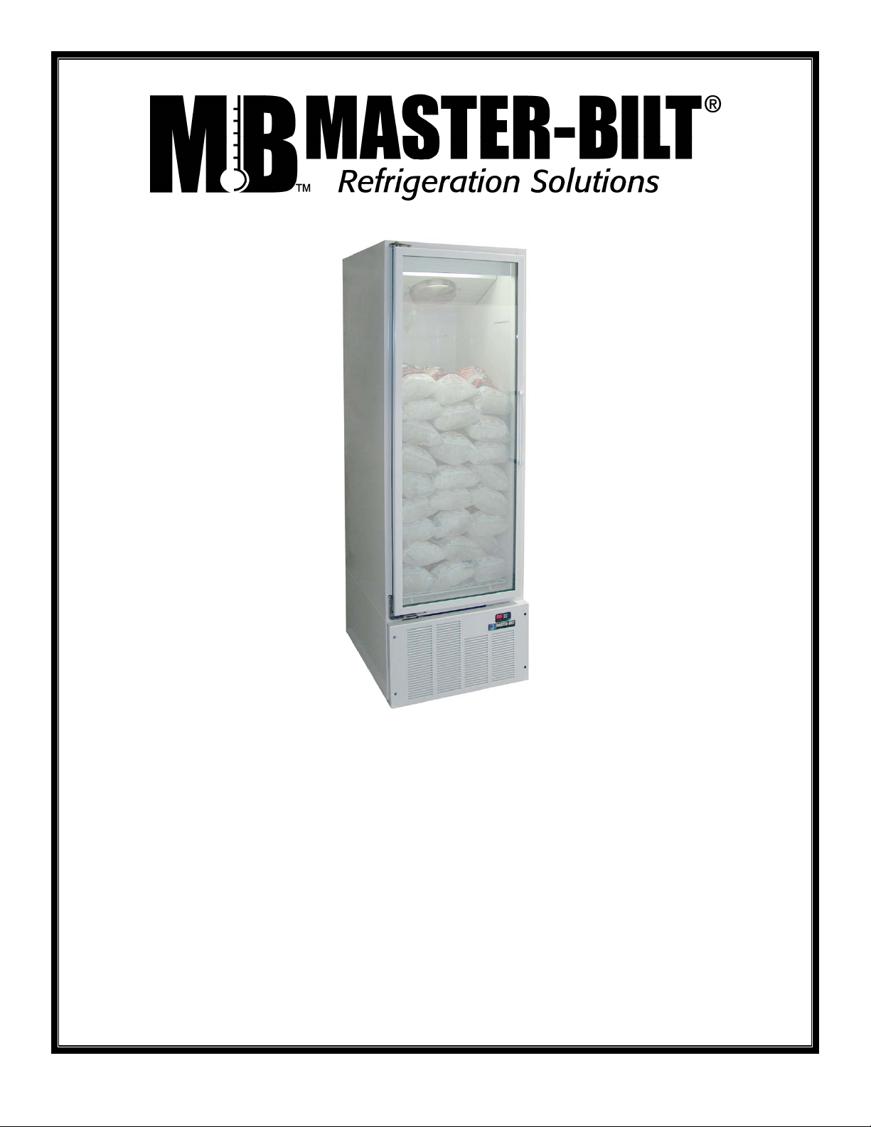
IM-23GB
Installation & Operations Manual
With TLY 25 Controller
Master-Bilt Products
908 Highway 15 North
New Albany, MS 38652
Phone: (800) 684-8988
LN_ 09/26/06
Page 2

2
Page 3

TABLE OF CONTENTS
INTRODUCTION................................................................................................................................................................4
STORE CONDITIONS........................................................................................................................................................4
WARNING LABELS AND SAFETY INSTRUCTIONS.......................................................................................................4
NOTICE ..............................................................................................................................................................................5
GENERAL INSTRUCTIONS..............................................................................................................................................5
MECHANICAL....................................................................................................................................................................6
MASTER-BILT ELECTRONIC REFRIGERATION CONTROL (TLY-25 6
OPERATION..........................................................................................................................................................8
MANUAL DEFROSTS...........................................................................................................................................8
HOW TO CHANGE SETPOINTS..........................................................................................................................8
LIST OF PARAMETERS .......................................................................................................................................9
ALARM & OTHER SIGNALS.................................................................................................................................9
ELECTRICAL CONNECTIONS .......................................................................................................................................10
PROBE CONNECTIONS .................................................................................................................................................10
SERVICE INSTRUCTIONS..............................................................................................................................................10
TROUBLE SHOOTING....................................................................................................................................................11
CHECK LIST....................................................................................................................................................................11
CABINET CLEANING PROCEDURES............................................................................................................................12
ICE MERCHANDISER MONTHLY CHECKLIST............................................................................................................12
PARTS LIST.....................................................................................................................................................................13
SALE AND DISPOSAL ....................................................................................................................................................14
WIRING DIAGRAMS........................................................................................................................................................15
3
Page 4
INTRODUCTION
Thank you for purchasing Master-Bilt Ice Merchandiser. This manual contains important instructions for installing,
using, cleaning, and servicing Master-Bilt Indoor Ice Merchandiser. A parts list is included with this manual. Read all
documents carefully before installing or servicing your equipment.
STORE CONDITIONS
The Master-Bilt Ice Merchandisers are designed to operate in a controlled environment. The temperature should be at
75°F or below for an indoor ice merchandiser, with relative humidity of 55% or less. At higher temperature or humidity
conditions, the performance of these merchandisers may be affected and the capacity diminished.
The Master-Bilt Ice Merchandiser should not be positioned where it is directly exposed to rays of the sun or near a
direct source of radiant heat or airflow. This will adversely affect the ice merchandiser and will result in poor
performance.
If this ice merchandiser is to be located against a wall, there should be at least 6” space between the wall and the back
of the unit. This space will allow for the circulation of air behind the ice merchandiser, which will prevent condensation
on the exterior surfaces.
WARNING LABELS AND SAFETY INSTRUCTIONS
This symbol is the safety-alert symbol. When you see this symbol on your ice merchandiser or in
this manual, be alert to the potential for personal injury or damage to your equipment. Be sure you
understand all safety messages and always follow recommended precautions and safe operating
practices.
NOTICE TO EMPLOYERS
You must make sure that everyone who installs, uses or services your cabinet is thoroughly familiar with all
safety information and procedures.
Important safety information is presented in this section and throughout the manual. The following signal words are
used in the warnings and safety messages:
DANGER: Severe injury or death will
WARNING: Severe injury or death can
CAUTION: Minor injury or damage to your cabinet can occur if you ignore the message.
NOTICE: This is important installation, operation or service information. If you ignore the message, you may
damage your cabinet.
The warning and safety labels shown throughout this manual are placed on your Master-Bilt Products cabinet
at the factory. Follow all warning label instructions. If any warning or safety labels become lost or damaged,
call your customer service department at (800)684-8988 for replacements
This label is attached on the cabinet
back and in the machine compartment.
occur if you ignore the message.
occur if you ignore the message.
CAUTION!
GROUND REQUIRED
FOR SAFE OPERATION
This label is located on the power cord.
4
Page 5
NOTICE
Read this manual before installing, cleaning, or performing any maintenance on your cabinet. Keep the
manual and refer to it before doing any service on the equipment. Failure to do so could result in personal
injury or damage to the cabinet.
DANGER
Improper or faulty hook-up of electrical components on the refrigeration units can result in
severe injury or death. All electrical wiring hook-ups must be done in accordance with all applicable local,
regional or national standards.
NOTICE
Installation and service of the refrigeration and electrical components of the cabinet must
be performed by a refrigeration mechanic and/or a licensed electrician.
The portions of this manual covering refrigeration and electrical components contain technical instructions intended
only for persons qualified to perform refrigeration and electrical work. This manual cannot cover every installation, use
or service situation. If you need additional information, call or write us:
Customer Service Department
Master-Bilt Products
Highway 15 North
New Albany, MS 38652
Phone (800) 684-8988
Fax (800) 684-8988
GENERAL INSTRUCTIONS
1. Be sure the ice merchandiser is properly installed by competent service people.
2. Keep the ice merchandiser clean and sanitary so it will meet your local sanitation codes. Clean the unit with a mild
detergent and water, then rinse.
3. Rotate your stock so that older stock does not accumulate.
4. Do not place product in the ice merchandiser when it is soft or partially thawed. Also, product should not be put in
the ice merchandiser for at least 6 hours after it is started.
5. Stock ice merchandiser as quickly as possible, exposing only small quantities to condition temperatures for short
periods of time.
NOTICE TO STORE OWNERS / MANAGERS
Moisture or liquid around or under the cabinet is a potential slip/fall hazard for persons walking by or working
in the general area of the cabinet. Any cabinet malfunction or housekeeping problem that creates a slip/fall
hazard around or under the cabinet should be corrected immediately
If moisture or liquid is observed around or under a Master-Bilt Ice Merchandiser, an immediate investigation should be
made by qualified personnel to determine the source of the moisture or liquid. The investigation should determine if the
ice merchandiser is malfunctioning or if there is a drainpipe leaking.
.
5
Page 6

MECHANICA L
Remove front grille and check refrigeration lines to see that they are free (not touching each other or compressor).
Spin condenser fan blade to see that it is free.
The compressor is hermetic so it is internally spring mounted and ready to run.
ELECTRICAL
WARNING
Before servicing electrical components in the case or the doors or door frames make sure all power to case is
off. Always use a qualified technician.
Check voltage and amps drawn on (Page 12-13) to determine proper line and fuse or circuit breaker size. Check power
supply for low voltage. If voltage reads “115” with no load, and it drops below “100” when the compressor tries to start,
it is an indication of too small supply wiring or too long to run.
It is recommended that a separate circuit be run for each ice merchandiser to prevent another appliance from blowing
the fuse or breaker, causing loss of product.
MASTER-BILT ELECTRONIC REFRIGERATION CONTROL (TLY-25)
GENERAL DESCRIPTION
The model TLY-25/29 is a digital controller with microprocessor that is typically used in cooling applications that have
temperature control with ON/OFF regulation and defrosting control with set time and hours intervals (Real Time Clock
Defrosting) by means of electrical.
The instrument has 3 relay outputs, two inputs for PTC or NTC temperature probes and a digital input, that can all be
configured.
The 3 outputs can be used for controlling the compressor or the temperature control device (OUT), the defrosting
device (DEF), the evaporation fan (FAN) or, alternatively any of the previous functions, using an auxiliary device (AUX)
or an alarm (AL).
The two inputs for the PTC and NTC temperature probes (which can be selected by parameter) can be used to
measure the cell temperature (Pr1) and the evaporator temperature (Pr2).
6
Page 7

MICROPROCESSOR-BASED DIGITAL ELECTRONIC FREEZER CONTROLLER
9
AL
TLY 25
4
3
2
Aux
1
-OK+
Fan AuxDefOut
10
712 136511 8
1 - Key P: Used for setting the Set point and for programming the function parameters
2 - Key DOWN/Aux: Used for decreasing the values to be set and for selecting the parameters. It can also be programmed via
the parameter “Fbd” to carry out other functions such as activating the Aux output, starting up the
continuous cycle, selecting the active set point or turning on and off (stand-by) the device.
3 - Key UP/DEFROST: Used for increasing the value to be set, for selecting the parameters and for activating manual defrosting.
4 - Key U: Used for visualising the temperatures taken by the cell probes and evaporator (Pr1 and Pr2) and the internal clock
(if present). It can also be programmed via the parameter “USrb” to carry out other functions, just like the
key DOWN/AUX (see par. 4.12).
5 - Led OUT: Indicates the compressor output status (or the temperature control device) on (on), off (off) or inhibited (flashing)
6 - Led DEF: Indicates defrosting in progress (on) or dripping (flashing).
7 - Led FAN: Indicates fan output status on (on), off (off) or delayed after defrosting (flashing)
8 - Led AUX: Indicates AUX output status on (on), off (off) or inhibited (flashing)
9 - Led AL: Indicates the alarm status (on), (off) and silenced or memorized (flashing)
10 - Led SET: Indicates the input in programming mode and the programming level of the parameters. It also serves to indicate
the Stand-by status.
11 - Led -: Indicates that a low temperature alarm is in progress (lit) or that a low temperature alarm has been memorised
(flashing).
12 - Led OK: Indicates that no alarms are in progress
13 - Led +: Indicates that a high temperature alarm is in progress (lit) or that a high temperature alarm has been memorised
(flashing)
7
Page 8

OPERATION
Fan The fan will run constantly except when a defrost is initiated, or when the evaporator temp is above
o
35
F. When in defrost mode the fan is off until the end of the defrost and the 2 minute drip time has
passed. There is 2 minutes delay after a def rost bef ore the fan comes on. The difference of t he evaporator
and room temperature of m ore than 9
minutes drip period.
Defrost The control uses time defrosts with four def rost per day for oil return safety. T he defrost timer
begins counting on power up. For example, if a def rost is desired at 12 am, 6 am, 12m, and 6 pm then
power up the unit at any of those four times.
MANUAL DEFROST
o
F will override the fan delay. FAN LED indicator is flashing during 2
1. Push this DEFROST
”UP/DEFROST” key for more than 5 seconds and a manual defrost will
start, if the conditions are correct, the led DEF will light up and the instrument will carry out a
defrosting cycle.
2. While in defrost, push and hold the DEFROST
key for more than 5 seconds and the
controller will end the defrost cycle. The controller will then enter drip mode for 2 minutes. The DEF
led is flashing in drip mode.
HOW TO CHANGE SET POINTS
1. Press the P until sp-1 is displayed.
2. Push UP ▲ or DOWN▼ arrows to change the value.
3. To Exit: Press
NOTE 1: The set value is stored even when the procedure is exited by waiting the time-out to expire.
NOTE 2: Master-Bilt’s SETPOINT is set at a recommended 20°F at the factory.
NOTE 3: If power is turned off to the unit, the set point returns to factory set value.
SET + UP ▲ or wait 20 seconds without pressing a key.
8
Page 9

LIST OF PARAMETERS
Here is a list of factory set parameters the value of which can not be change in the field without the
password.
Symbols Descriptions Range M/B Setting
SPAt
SP1
SP2
SEnS
Unit
diSP
HSEt
tonE
toFE
dtyP
dint
dEFE
tEdF
tdCO
dLo
FLt
PtC
od
HAL
ALd
Active Set point 1 ÷ 2
Set Point 1 SPLL ÷ SPHL
Set Point 2 SPLL ÷ SPHL
Probes Type Ptc - ntc
Unit of measurement °C - °F
Normal Display (Room Temperature) OFF - Pr1 - Pr2 - SP - CL
Differential 0 ÷ 30 °C/°F
Compressor will run for 6 minutes OFF ÷ 99.59 min.sec
Then off for 4 Minutes OFF ÷ 99.59 min.sec
EL = electrical Defrost EL - in
Defrosting interval OFF ÷ 99.59 hrs.min
Max. length of defrost cycle 0.01 ÷ 99.59 min.sec
Defrost stop temperature - 58 ÷ 302 °C/°F
Compressor delay after defrost (drainage time) OFF ÷ 99.59 min.sec
Defrost display On - OFF - Lb
High temperature fan off - 58 ÷ 302 °C/°F
Compressor protection time OFF ÷ 99.59 min.sec
Delay at power on OFF ÷ 99.59 min.sec
High temperature Alarm threshold OFF / - 58 ÷ 302 °C/°F
Temperature Alarms delay OFF ÷ 99.59 min.sec
1
20
20
ntc
°F
Pr1
5
6.00
4.00
EL
6.00
30.00
55
2.00
lb
45
1.00
0.10
32
30
ALARM SIGNALS
Message Cause Outputs
-E1
E1
-E2
E2
AL
EEPr
Reading Outside Range Inputs
Probe 1 bad or dis connected Control goes into fail safe mode. Compressor on 6 minutes
Reading Outside Range Defrost end is timed
Probe 2 bad or disconnected Inputs
Allarm in Progress Outputs unchanged.
Inernal Memory Error Inputs
and of 4 minutes.
OTHER SIGNALS
Message Reason
od
dEF
PdEF
CC
HI
LO
AL
AP
Delay in switching on in progress
Defrosting in progress with “dLo” = Lb
Post-defrosting in progress with “dLo” = Lb
Continous Cycle in progress
Maximum temperature alarm in progress
Minimum temperature alarm in progress
Digital input alarm in progress
Door Open
9
Page 10

ELECTRICAL CONNECTIONS
The controller is provided with screw terminal block to connect cables with a cross section up to 2,5 mm
connecting cables make sure the power supply complies with the control’s requirements. Separate the probe cables
from the power supply cables, from the outputs and the power connections. Do not exceed the maximum current
allowed on each relay, in case of heavier loads use a suitable external relay.
2
. Before
PROBE CONNECTIONS
The probes shall be mounted with the bulb upwards to prevent damage due to casual liquid infiltration. It is
recommended to place the thermostat probe away from air streams to correctly measure the average room
temperature. Place the defrost termination probe among the evaporator fins in the coldest place, where most ice is
formed, far from heaters or from the warmest place during defrost, to prevent premature defrost termination.
SERVICE INSTRUCTIONS
1. High head pressure and high back pressure:
A. Condenser coil clogged or restricted
B. Condenser fan motor defective.
C. Air discharge in rear of cabinet restricted.
2. Low back pressure and low head pressure:
A. Restriction in system.
B. Refrigerant undercharged.
C. Leak in system
3. Pressure normal – cabinet warm:
A. Coil blocked with frost (see #4).
B. Refrigerant undercharged.
C. Control set too warm.
4. Ice merchandiser not cycling – coil blocked with frost:
A. Defective temperature controller, or improper settings.
B. Refrigerant overcharged.
C. Location too hot.
D. Condenser clogged.
E. Condenser fan motor defective.
F. For freezer, defrost heater not operating.
G. Air leakage into ice merchandiser due to open door or faulty door seal.
5. Compressor starts and runs – but cycles on overload:
A. Low voltage
B. Relay defective.
C. Overload defective.
D. High head pressure (see #1).
10
Page 11

TROUBLE SHOOTING
Symptom-System Oper ates Long or Continuously
Possible Problem Possible Cause Remedy
How Long do the doors stay open? Door closer need adjust. Adjust door closer and keep doors closed.
Is the condenser clean? Dirty condenser. Clean condenser
Are the condenser fans running? Fans not running. Repair or replace
Is the evaporator dirty or iced up? Iced or plugged evaporator coil(s). Defrost or clean (check control settings)
Are the evaporator fans running? Fans not running. Repair or replace
Have you checked the refrigerant level? Shortage of refrigerant. Repair leak and recharge.
Is there air or other non-condensables in Non-condensables in the system Evacuate and recharge.
the system?
Are all controls functioning properly? Control contacts or error codes. Repair or adjust the control.
Checked expansion valve for Freezers? Improper controls adjusted. Clean or replace.
What is Evaporator Superheat? Evaporator Superheat too high. Adjust expansion valve to lower
Superheat setting.
Where is condensing Unit located? Location too warm. Ventilate area or change to cooler
Air leaks or doors location.
Is Box well sealed from air penetrations? Wall panels not locked or wall Seal leaks, adjust doors or
pentrations not sealed. replace.
Is system capacity sufficient for product Product load greater than system add additional units or replace.
load? capacity.
CHECK LIST
A. Check operating pressures.
B. Check electrical requirements of unit to supply voltage.
C. Set temperature control for desired temperature range.
D. Check condensing unit for vibrating or rubbing tubing. Dampen and clamp as required.
E. Replace all service valve caps and latch unit covers.
F. Check that evaporator fan runs after initial pull down.
11
Page 12

CABINET CLEANING PROCEDURES
WARNING!
To avoid electrical shock, disconnect main power supplies to the merchandiser
before beginning this procedure. May have more than one disconnect switch.
The exterior of the ice merchandiser should simply be wiped clean with a damp cloth daily. This will be sufficient to
keep the unit looking its finest. Do not use a brush, scouring pad, or any abrasive material on the painted
surfaces!
To clean the interior of the ice merchandiser, the condensing unit and power to the merchandiser fans and heaters
should be shut off. Disconnect all power before cleaning! All product in the cabinet should be removed and stored
in an appropriate facility. All shelving, trays, etc. should be removed and cleaned separately.
The interior (as well as the exterior) of the ice merchandiser may be cleaned with a germicidal detergent at the
manufacturer’s recommended concentration. Do not use any ammonia-based products as this may damage the
electrical components in the unit. Again, do not use a brush, scouring pad, or any abrasive material on the painted
surfaces. Use a soft brush or cleaner pad for built-up dirt, stains, or spills. Remove only the necessary mechanical
parts to access the evaporator coil and fan housing. Care should be taken not to unnecessarily soak fan motors,
electrical connections, controls, or any wire raceway. Wipe all surfaces with a damp cloth. A sanitizer should then be
thoroughly sprayed onto the surfaces and again wiped with a damp cloth.
Remove only the necessary mechanical parts to access the condenser coil and compressor housing. Care should
again be taken not to unnessarily soak fan motors, electrical connections, time clock, ballasts, or any wire raceway.
Check the condenser coil to insure that it is not clogged with dirt, dust, or lint. A dirty or clogged condenser coil will
result in diminished performance of the cabinet. The condenser should be brushed with a plastic bristled brush. For
dust or dirt that has accumulated deep inside the condenser, use compressed air to blow the dirt through the coil. Do
not let dust or dirt accumulate on the fan blades. If dust or dirt is noticeable, simply wipe the fan blades with a damp
cloth as with other surfaces. After cleaning, replace any equipment that was previously removed and start the
condensing unit and return power to the lights, fans, and heaters.
CLEANING:
depending on store conditions.
Keep the equipment clean and sanitary so it will meet your local sanitation codes. Wipe up all spills, clean with water
and a mild detergent, then rinse with clean water. Wipe the exterior and gasket area as needed.
As a regular maintenance routine, the condenser coil should be cleaned approx every 6 to 12 months,
ICE MERCHANDISER MONTHLY CHECKLIST
1. Check condenser coil, clean if necessary.
2. Check service valves for leaks evident by oil traces.
3. Check for obstruction restricting air flow over the evaporator coil and the condenser coil.
Insure that the air intake is not obstructed.
4. Check for excessive noise.
5. Check for proper temperature, adjust if necessary.
6. Check door gaskets for proper seal against cabinet.
7. Check doors for self closing, adjust tension if necessary.
6. Check for proper operation sequence in normal refrigeration cycle and defrost cycle.
12
Page 13

PARTS LIST
PART DESCRIPTION IM-23
Condensing unit/1st run units
Compressor (AEA44440YXA)
Bottom Shelf
Light Switch
Ballast
evaporator coil
evaporator fan motor
evaporator fan blade
evaporator fan guard
Wall Gard
drain flanges with adapter
drain line heater wire
heater clip
drier
grill
rear Cover
Cap Tube
heater safety
vinyl tube
coil defrost heater
TLY-25 Control w/ Sensors
TLY Controller
Sensors
glass door
Starter
Leg Leueler
Condensate Pan
toggle switch
Evap Motor Bracket
condensate pan clip
Lamps 15W
Lamp Shield
Rear Grille
01-01733
03-50330
33-01453
23-50562
23-00349
07-13288
13-13198
15-13106
25-01324
25-01344
11-01410
17-00404
17-09431
09-09308
256-28900
255-11714
11-01450
19-01164
11-00876
17-09407
19-13952
19-13992
19-13953
31-02672
23-01092
27-00592
001-13001
19-3118
13-13165
21-01284
23-00329
25-01273
25-00104
13
Page 14

SALE AND DISPOSAL
OWNER RESPONSIBILITY
If you sell or give away your Master-Bilt Ice Merchandiser you must make sure that all safety labels and the Installation
- Service Manual are included with it. If you need replacement labels or manuals, Master-Bilt will provide them free.
Contact the customer service department at Master-Bilt at (800)-647-1284.
The customer service department at Master-Bilt should be contacted at the time of sale or disposal of your cabinet so
records may be kept of its new location.
14
Page 15

15
 Loading...