

Page 1

BOTTOM MOUNT REFRIGERATORS, FREEZERS & MERCHANDISERS
Installation, Operation and Maintenance Technical Instructions
FREEZERS : F23-S, F23-SH
F49-S, F49-SH
F72-S, F72-SH
REFRIGERATORS : R23-S, R23-SH, R23-G
R49-S, R49-SH, R49-G
R72-S, R72-SH, R72-G
MERCHANDISERS : GR26H, GR48S, GR72H
- 1 – 05/15 Rev. G 146526
Page 2

A. GENERAL
1. SPECIFICATION - - - - - - - - - - - - - - - - - - - - - - - - - - - - - - - - A3
1) GENERAL
2) MAIN COMPONENTS
2. REFRIGERATION CYCLE - - - - - - - - - - - - - - - - - - - - - - - - - - A9
3. TROUBLE SHOOTING - - - - - - - - - - - - - - - - - - - - - - - - - - - - - A11
1) CHECKING THE POWER SUPPLY
2) CHECKING THE POWER SUPPLY OF CONT ROL BOARD
3) CHECKING THE CONTROL PART OF REFRIGERATION CYCLE
4) CHECKING THE DEFROST PART
5) WHEN THE UNIT DOES NOT COOL
6) WHEN THERE IS A ABNORMAL NOISE
7) WHEN THE TEMPERATURE DOES NOT DISPLAY
8) WHEN THE LAMP DOES NOT LIGHT
9) CHECKING SENSOR
4. FEATURE CHART - - - - - - - - - - - - - - - - - - - - - - - - - - - - - - - - A22
5. WIRING DIAGRAM - - - - - - - - - - - - - - - - - - - - - - - - - - - - - - - - A28
6. REPLACEMENT OF COMPONENTS - - - - - - - - - - - - - - - - - - A37
- 2 – 05/15 Rev. G 146526
Page 3
1. SPECIFICATION
(27.4”)
(55.2”)
(78.0”)
(27.4”)
(55.2”)
(78.0”)
(23.6”)
(51.4”)
(74.2”)
(23.6”)
(51.4”)
(74.2”)
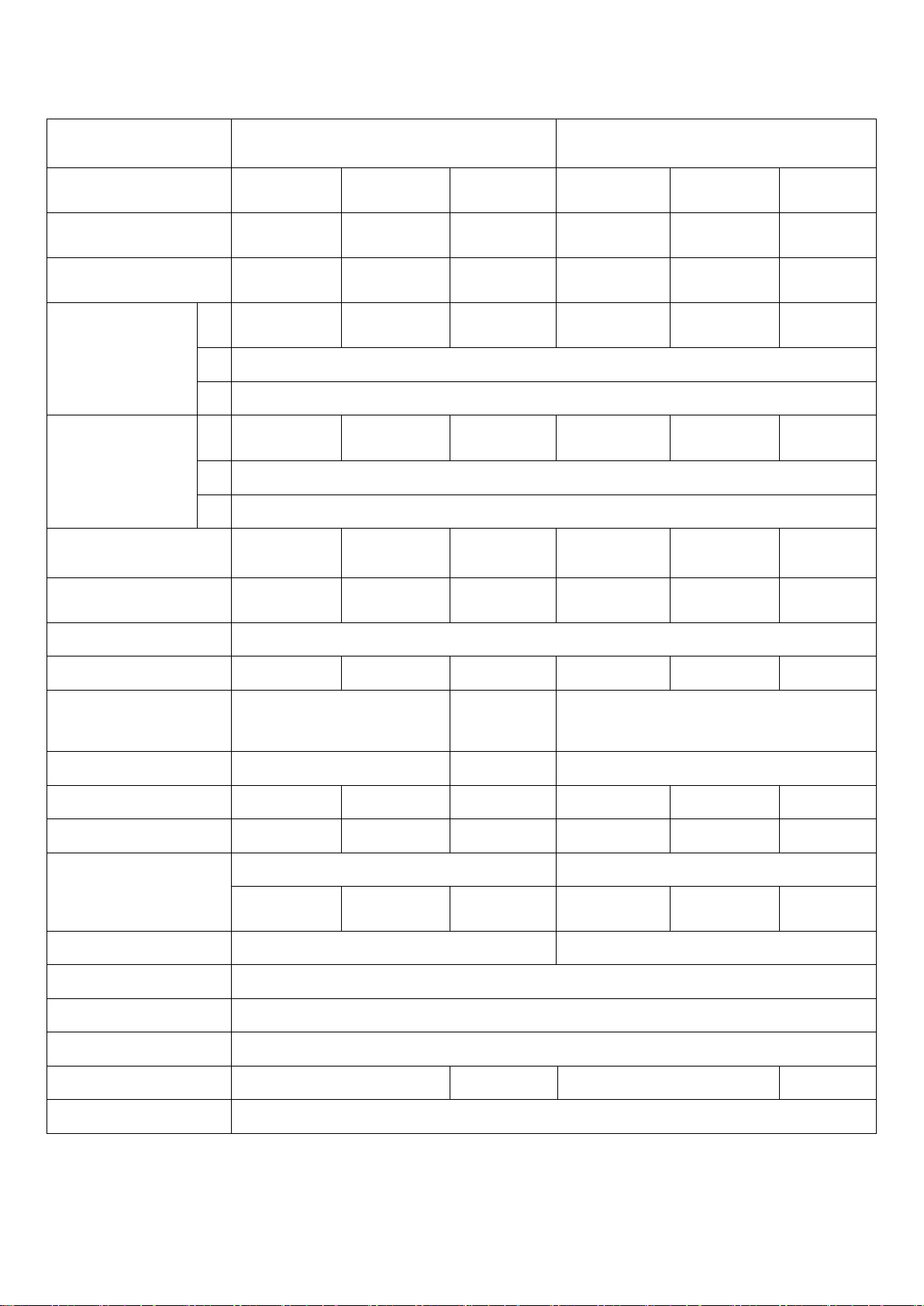
1.1 GENERAL - SOLID DOOR FREEZER & REFRIGERATOR (FULL DOOR / HALF DOOR)
PRODUCT
MODEL
Capacity
Net Capacity
Exterior Dimension
(Including casters
Door Handles)
Interior Dimension
Product Weight
(W)
(D)
(H)
(W)
(D)
(H)
SOLID (FULL/HALF) DOOR
F23-S /
F23-SH
650ℓ(23ft3)/
648ℓ(22.9ft3)
552ℓ(19.5ft3)/
551ℓ(19.4ft3)
695㎜
600㎜
124㎏(273 lb)/
126㎏(278 lb)
FREEZER
F49-S /
F49-SH
1,385ℓ(49ft3)/
1,381ℓ(48.8ft3)
1,195ℓ
(42.2 ft3)/
1,191ℓ(42.1 ft3)
1,400㎜
1,305㎜
194㎏(428 lb)/
198㎏(437 lb)
F72-S /
F72-SH
2,035ℓ(72ft3)/
2,028ℓ(71.6ft3)
1,790ℓ
(63.2ft3)/
1,782ℓ(63ft3)
1,980㎜
838 ㎜ (33”)
2,127 ㎜ (83.7”)
1,885㎜
635 ㎜ (25”)
1,545 ㎜ (60.8”)
255㎏(562 lb)/
260㎏(573 lb)
SOLID (FULL/HALF) DOOR
R23-S /
R23-SH
650ℓ(23ft3)/
648ℓ(22.9ft3)
552ℓ
(19.5ft3)/
551ℓ(19.4ft3)
695㎜
600㎜
121㎏(267 lb)/
123㎏(271 lb)
REFRIGERATOR
R49-S /
R49-SH
1,385ℓ(49ft3)/
1,381ℓ(48.8ft3)
1,195ℓ
(42.2 ft3)/
1,191ℓ(42.1 ft3)
1,400㎜
1,305㎜
186㎏(410 lb)/
190㎏(419 lb)
R72-S /
R72-SH
2,035ℓ(72ft3)/
2,028ℓ(71.6ft3)
1,790ℓ
(63.2ft3)/
1,782ℓ(63ft3)
1,980㎜
1,885㎜
253㎏(558 lb)/
258㎏(569 lb)
Door Type
Swing 1EA/
Swing 2EA
Swing 2EA/
Swing 4EA
Swing 3EA/
Swing 6EA
Swing 1EA/
Swing 2EA
Swing 2EA/
Swing 4EA
Door Material Stainless steel (STS)
Shelves 4EA 8EA 12EA 4EA 8EA 12EA
AC 115V
Power Voltage AC 115V/60Hz
Plug in - Installation NEMA 5-15P NEMA 14-20P
/208-230V
60Hz
AC 115V/60Hz
NEMA 5-15P
Amps 8.5A 9.5A 9.0A 7.5A 7.5A 10.0A
Compressor 3/5HP 3/4HP 9/8HP 3/8HP 3/8HP 1/2HP
R-404A R-134a
Refrigerant
Range of Temperature
Door auto-close equipment
340 g
(12.0 oz)
630 g
(22.2 oz)
670 g
(23.6 oz)
210 g
(7.5 oz)
270 g
(9.5 oz)
Below -18℃ (0°F) 0℃ ~ 4℃ (+32°F ~ +40°F)
Auto-close for Spring
Door stop 120˚ Stop
Swing 3EA/
Swing 6EA
400 g
(14.0 oz)
Air suction equipment Air damper
Caster 4” × 4EA 4” × 6EA 4” × 4EA 4” × 6EA
Condensing unit Sliding Type
◈ Above specifications are subjected to ch ange without prior notice for quality improvement.
◈ The nameplate(includes Serial Nu mb er ) is l ocated on the upper left of the cabi net interior.
- 3 – 05/15 Rev. G 146526
Page 4
(23 ft3)
(49 ft3)
(72 ft3)
(19.5 ft3)
(42.2 ft3)
(63.2 ft3)
(27.4”)
(55.2”)
(78.0”)
(23.6”)
(51.4”)
(74.2”)
(278 lb)
(441 lb)
(597 lb)
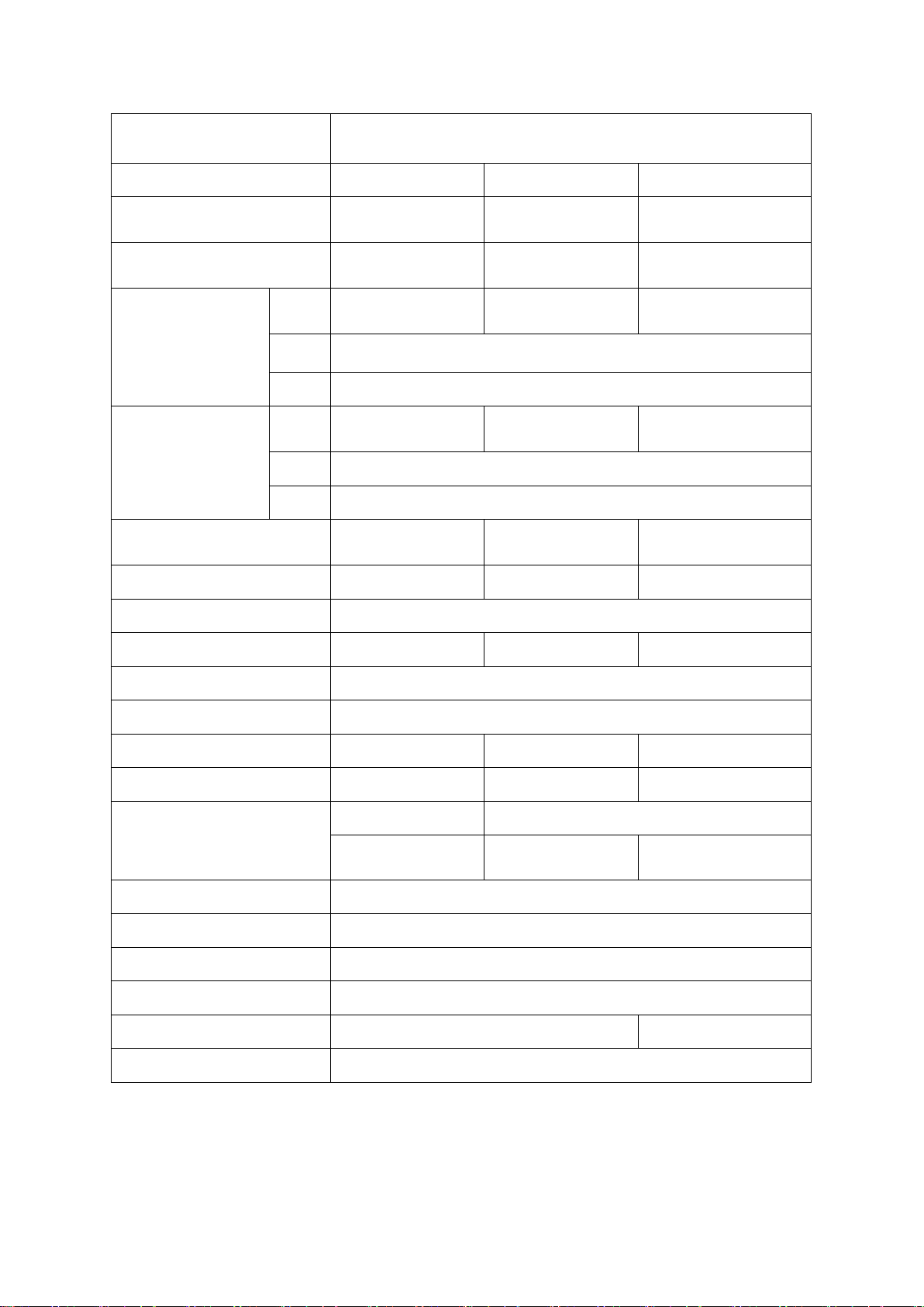
1.2 GENERAL - GLASS DOOR REFRIGERATOR
PRODUCT
MODEL R23-G R49-G R72-G
Capacity
Net Capacity
Exterior Dimension
(Including casters
Door Handles)
Interior Dimension
Product Weight
Door Type Swing 1EA Swing 2EA Swing 3EA
(W)
(D)
(H)
(W)
(D)
(H)
GLASS (FULL) DOOR REFRIGERATOR
650 ℓ
552 ℓ
695㎜
600㎜
126㎏
1,385 ℓ
1,195 ℓ
1,400㎜
835 ㎜ (32.9”)
2,127 ㎜ (83.7”)
1,305㎜
635 ㎜ (25”)
1,545 ㎜ (60.8”)
200㎏
2,035 ℓ
1,790 ℓ
1,980㎜
1,885㎜
271㎏
Door Material Stainless steel (STS)
Shelves 4EA 8EA 12EA
Power Voltage AC 115V/60Hz
Plug in - Installation NEMA 5-15P
Amps 5.0A 7.5A 8.0A
Compressor 3/8HP 3/5HP 3/5HP
R-134a R-404A
Refrigerant
Range of Temperature
Door auto-close equipm ent Auto-close for Spring
Door stop 120˚ Stop
Air suction equipment Air damper
Caster 4” × 4EA 4” × 6EA
Condensing unit Sliding Type
220 g
(7.8 oz)
320 g
(11.3 oz)
0℃ ~ 4℃ (+32°F ~ +40°F)
640 g
(22.6 oz)
◈ Above specifications are subjected to ch ange without prior notice for quality improvement.
◈ The nameplate(includes Serial Nu mb er ) is l ocated on the upper left of the cabi net interior.
- 4 – 05/15 Rev. G 146526
Page 5

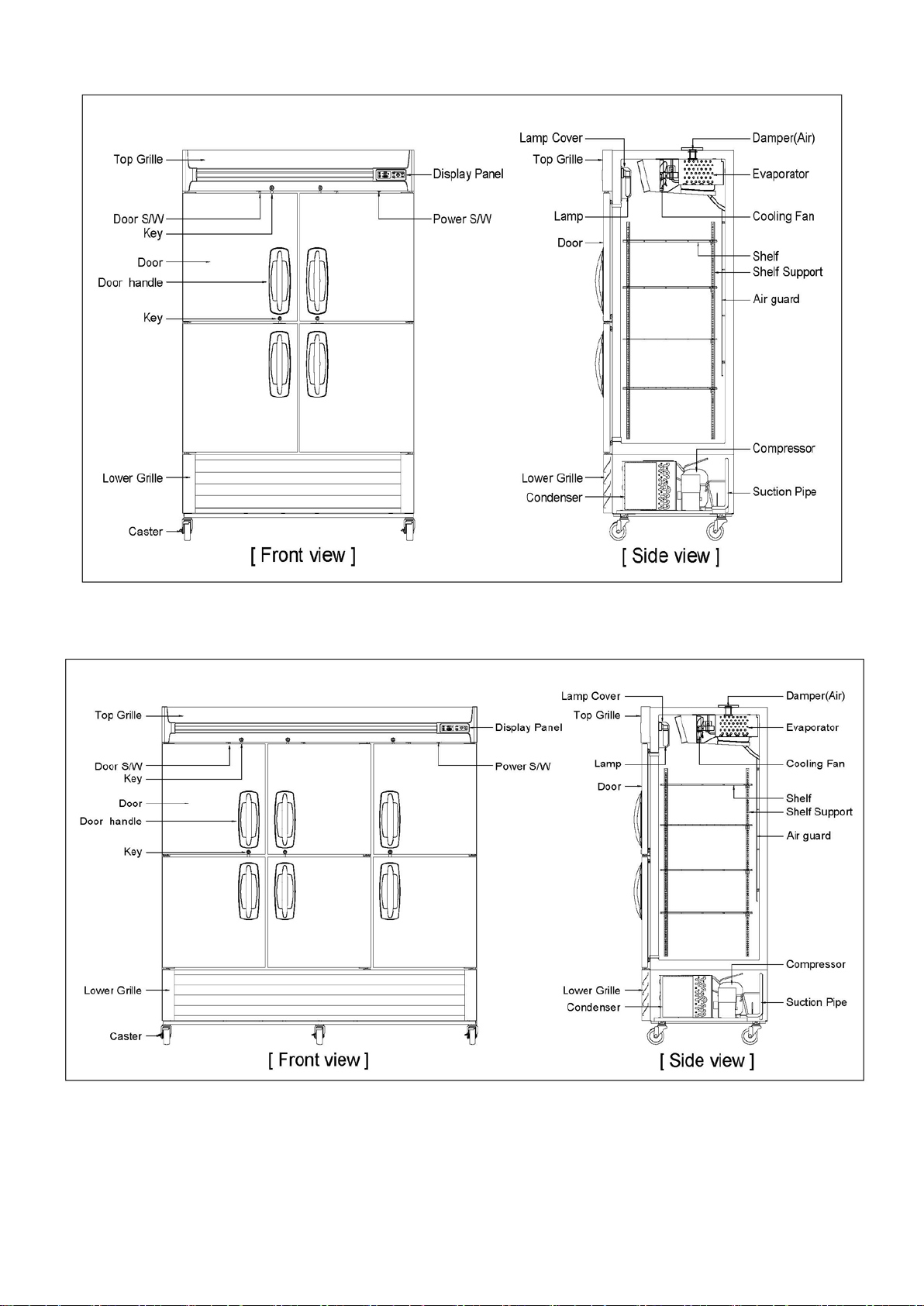
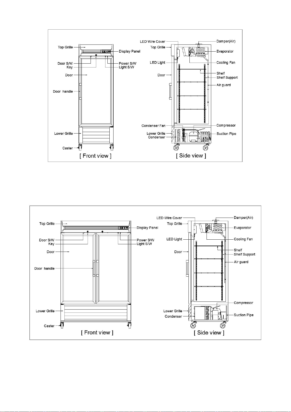
2.1 MAIN COMPONENTS - SOLID DOOR FREEZER & REFRIGERATOR
France)
France)
CAJ4461Y(A)
France)
Type of Compressor
motor
189~227㎌
/ 165V
315㎌ /
160V
Evaporator pipe
Diameter
12.7mm
(1/2”)
12.7mm
(1/2”)
Condenser pipe
Diameter
Interior Temp.
Indication
PRODUCT
MODEL
Compressor
(Manufacture)
Compressor
Capacity(kcal/h)
SOLID (FULL/HALF) DOOR
FREEZER
F23-S /
F23-SH
NEK2150GK
(Embraco)
F49-S /
F49-SH
CAJ2432Z(A)
(Tecumseh-
F72-S /
F72-SH
CAJ2446Z(H)
(Tecumseh-
LBP 628 LBP 808 LBP 1219 LBP 303 HBP 1586
SOLID (FULL/HALF) DOOR
REFRIGERATOR
R23-S /
R23-SH
R49-S /
R49-SH
SK1A1C-L2W
(Samsung-Korea)
R72-S /
R72-SH
(Tecumseh-
CSR CSIR
Compressor O.L.P T0873/G9 GA3PJU00 MST00AHN 4TM795TFBZZ-53 GA3SJU81
Compressor Relay
Starting Capacitor
Running Capacitor
RVA9AD3C-
121
25 ㎌ / 400V 30 ㎌ / 400V 15 ㎌ / 160V 12㎌ / 250V
3ARR3*5R* 3ARR3*3A* J531Q34E220M350-3 3ARR18A100B
88 ㎌ / 160V 125 ㎌ / 125V 250 ㎌ / 160V
-
Type of Evaporator Cu pipe + Al fin + Blue color coating
9.52mm (3/8")
9.52mm (3/8")
Cooling Fan Motor IS3225LTSA, 120V/60Hz
Type of Condenser Cu pipe + Al fin
9.52mm (3/8")
Condenser Fan Motor MA7425W1, 120V/60Hz
Dryer OD 25.4mm (1"), XH-9, 30g(1.06oz)
Temperature Control Thermistor
Running Indication Digital Display
Digital Display
Interior Lamp
(Incandescent lamp)
40W × 1EA 40W × 2EA 40W × 1EA 40W × 2EA
Defrost for evaporator Heated defrost (Control of thermistor) Off cycle
Defrost sheath heater 450W 670W 944W -
Defrost pan heater 60W 90W 128W -
Drain heater 9W -
Door switch SP201R-7DR, AC125V
Power switch SL112A, AC125V/12A
- 5 – 05/15 Rev. G 146526
Page 6
Type of Compressor
motor
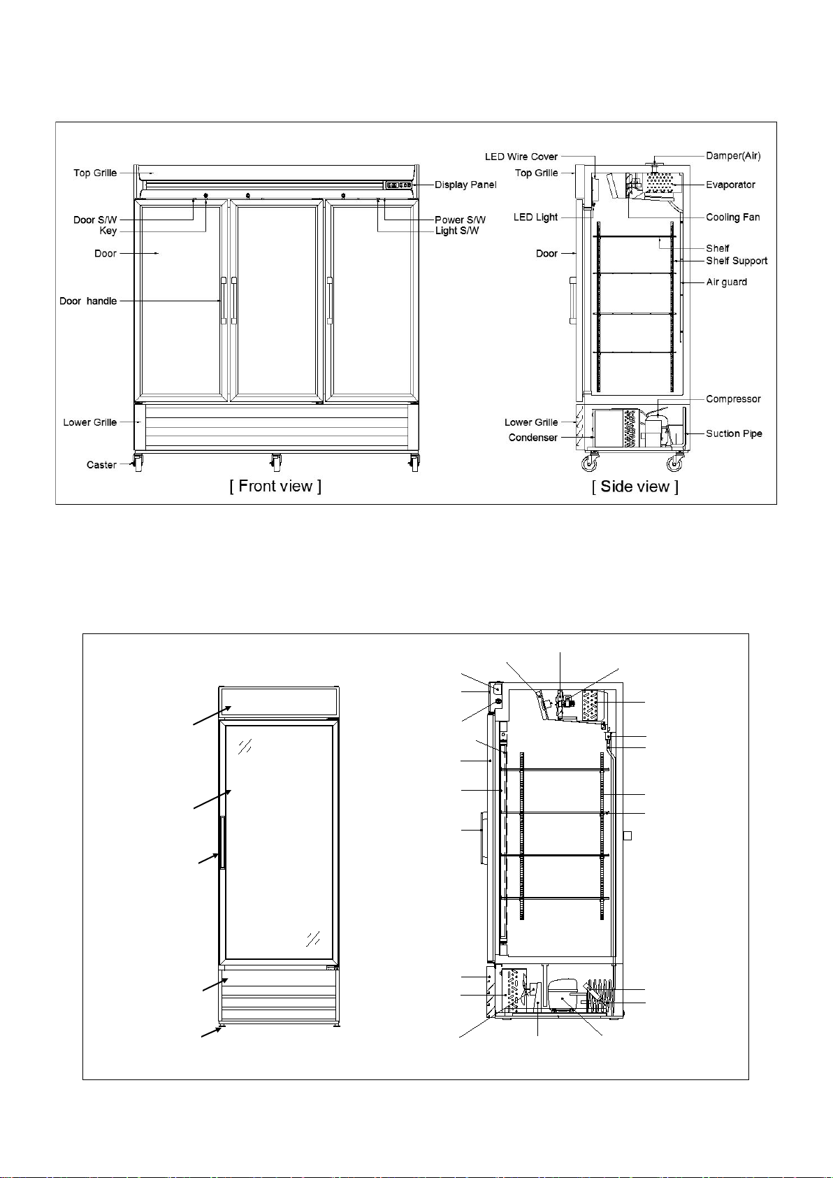
2.2 MAIN COMPONENTS - GLASS DOOR REFRIGERATOR
PRODUCT
MODEL R23-G R49-G R72-G
Compressor
(Manufacture)
Compressor Capacity(kcal/h)
Compressor O.L.P 4TM795TFBZZ-53 T0873/G9
Compressor Relay J531Q34E220M350-3 RVA9AD3C-121
Starting Capacitor
Running Capacitor
Type of Evaporator Cu pipe + Al fin + Blue color coating
Evaporator pipe Diameter 9.52mm (3/8") 12.7mm (1/2”)
Cooling Fan Motor IS3225LTSA, 120V/60Hz
(Samsung-Korea)
GLASS (FULL) DOOR REFRIGERATOR
SK1A1C-L2W
LBP 303 LBP 628
CSR
125 ㎌ / 125V 189~227 ㎌ / 165V
12 ㎌ / 250V 25 ㎌ / 400V
NEK2150GK
(Embraco)
Type of Condenser Cu pipe + Al fin
Condenser pipe Diameter 9.52mm (3/8")
Condenser Fan Motor MA7425W1, 120V/60Hz
Dryer OD 25.4mm (1"), XH-9, 30g(1.06oz)
Temperature Control Thermistor
Running Indication Digital Display
Interior Temp. Indication Digital Display
Interior Lamp (LED) 6W x 1EA 6W x 2EA 6W x 3EA
Defrost for evaporator Off cycle
Defrost sheath heater -
Defrost pan heater -
Drain heater -
Door switch SP201R-7DR, AC125V
Power switch SL112A, AC125V/12A
Light switch RL1-3, 16A/250V, ON-OFF
- 6 – 05/15 Rev. G 146526
Page 7
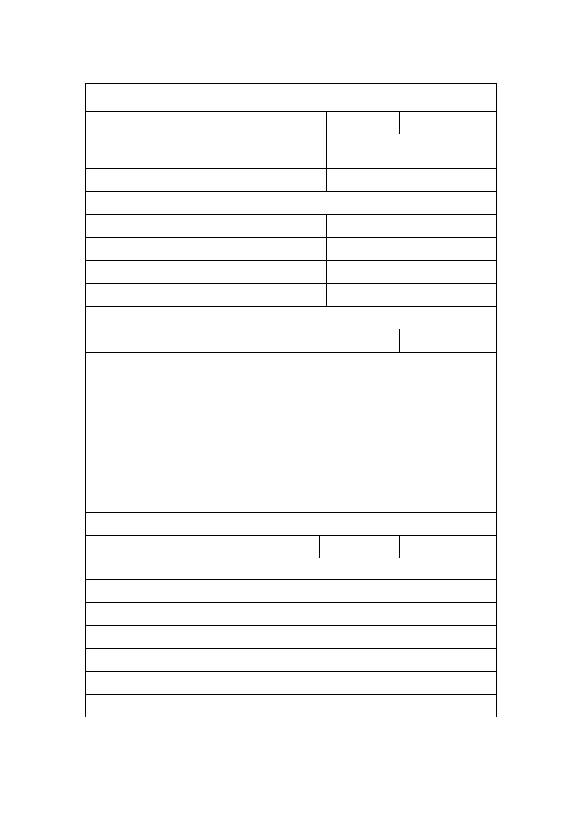
3.1 GENERAL - MERCHANDISERS
PRODUCT
MODEL GR26H GR48S GR70H
Capacity
Net Capacity
Exterior Dimension
(Including casters
Door Handles)
Interior Dimension
Net Weight
Door Type Swing 1EA Sliding 2E A Swing 3EA
Door Material Glass + PVC Glass + PVC Glass + Al
Shelves 4EA 8EA 12EA
(W)
(D)
(H)
(W)
(D)
(H)
MERCHANDISERS
736 ℓ (26 ft
677 ℓ (23.9 ft
3
) 1359 ℓ (48 ft3) 1982 ℓ (70 ft3)
3
) 1339 ℓ (47.3 ft3) 1877 ℓ (66.3 ft3)
720㎜ (28.4”) 1,350 ㎜ (53.2”) 1,980㎜ (78”)
844㎜ (33.3”) 780 ㎜ (30.7”) 835 ㎜ (32.9”)
2,017㎜ (79.4”) 2,012 ㎜ (79.2”) 2,126 ㎜ (83.7”)
640㎜ (25”) 1,280 ㎜ (50.4”) 1,885 ㎜ (74.2”)
719㎜ (28.3”) 642 ㎜ (25.3”) 635㎜ (25”)
1,584㎜ (62.4”) 1,562 ㎜ (61.5”) 1,545 ㎜ (60.8”)
130㎏ (287 lb) 215㎏ (474 lb) 325㎏ (716 lb)
Power Voltage AC 115V/60Hz
Plug in - Installation NEMA 5-15P
Amps 3.9A 10.0A 11.9A
Compressor 1/4 HP 1/2 HP 1/2 HP
R-134a R-134a R-134a
Refrigerant
300g (10.6 oz) 460g (16.2 oz) 500g (17.6 oz)
Range of Temperature
0℃ ~ 4℃ (32℉ ~ 40℉)
Door auto-close equipm ent Auto-close for Spring Auto-close for slope Auto-close for Spring
Door stop equipment 120˚ Stop - 120˚ Stop
Air suction equipment - - Air damper
Caster Adjust foot 4EA Adjust foot 6EA Adjust foot 6EA
Condensing unit Sliding Type
Door switch - - -
Power(or Lamp) switch SL112A, AC125V/12A
◈ Above specifications are subjected to ch ange without prior notice for quality improvement.
◈ The nameplate(includes Serial Nu mb er ) is l ocated on the upper left of the cabi net interior.
- 7 – 05/15 Rev. G 146526
Page 8
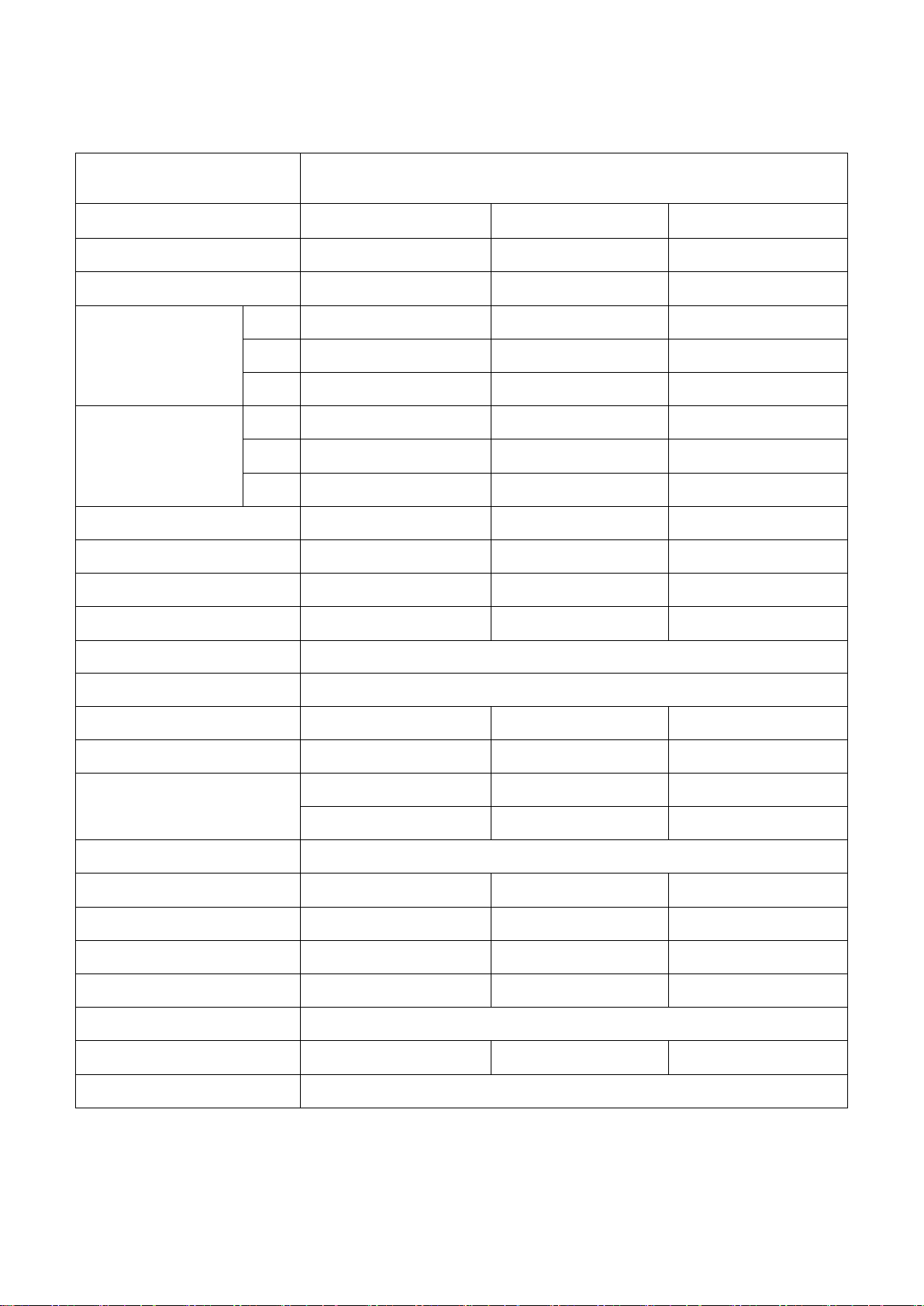
4.1 MAIN COMPONENTS - MERCHANDISERS
PRODUCT
MODEL GR26H GR48S GR70H
Compressor
(Manufacture)
Compressor Capacity(kcal/h) LBP 256 HBP 1946 HBP 1946
Type of Compressor motor RSCR CSIR CSIR
Compressor O.L.P 4TM444NHBYY CRA38014 CRA38014
Compressor Relay J531Q32E4R7M1802 3ARR3*2M* 3ARR3*2M*
Starting Capacitor -
Running Capacitor
Type of Evaporator Cu pipe + Al fin
Evaporator pipe Diameter 9.52 mm (3/8") 12.7mm (1/2”)
Cooling Fan Motor IS3225LTSA, 120V/60Hz
Type of Condenser Cu pipe + Al fin
SK182C-L2U
(SAMSUNG)
12 ㎌/250V
MERCHANDISERS
CAJ4476Y(A)
(Tecumseh-France)
250 ㎌/160V 250 ㎌/160V
- -
CAJ4476Y(A)
(Tecumseh-France)
Condenser pipe Diameter 9.52 mm (3/8")
Condenser Fan Motor MA7425W1, 120V/60Hz
Dryer OD 25.4mm (1"), XH-9, 30g(1.06oz)
Temperature Control
Running Indication -
Interior Temp. Indication -
Interior Lamp
(Fluorescent lamp)
Ad. Panel Fluorescent Lamp 20W × 1EA 32W × 1EA 32W × 2EA
Ballast 32W(Double)×1EA 32W(Double)×1EA 32W(Double)×2EA
Ballast Name
(Manufacture)
Defrost for evaporator Off cycle
Defrost sheath heater - - -
Defrost pan heater - - -
Thermostat
(GNF-250L)
32W × 1EA 32W × 1EA 32W × 2EA
B232I120RH-A
(ADVANCE)
Thermostat
(GNF-240L)
B232I120RH-A
(ADVANCE)
Thermostat
(GNF-246L)
B232I120RH-A
(ADVANCE)
Drain heater - - -
- 8 – 05/15 Rev. G 146526
Page 9
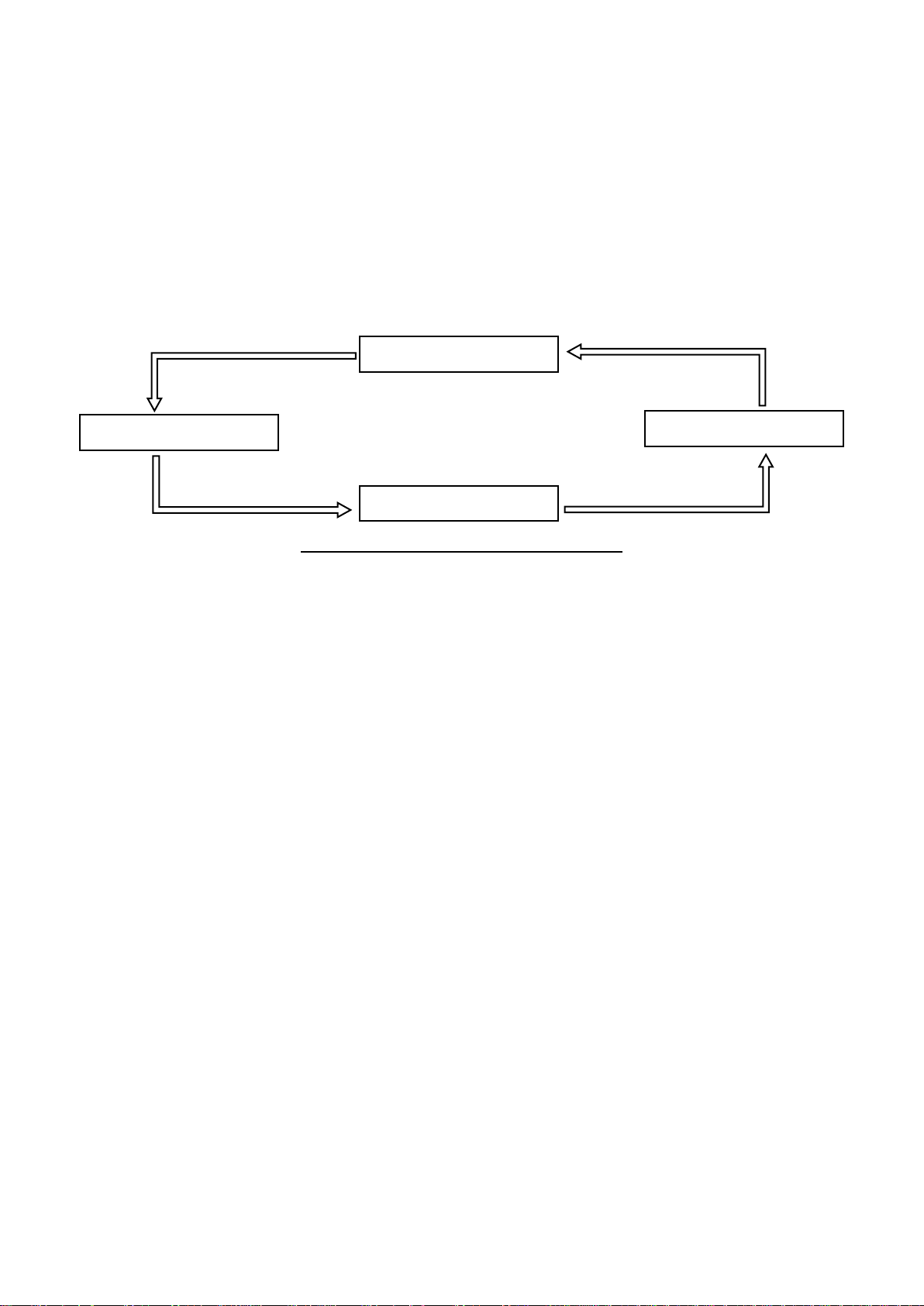
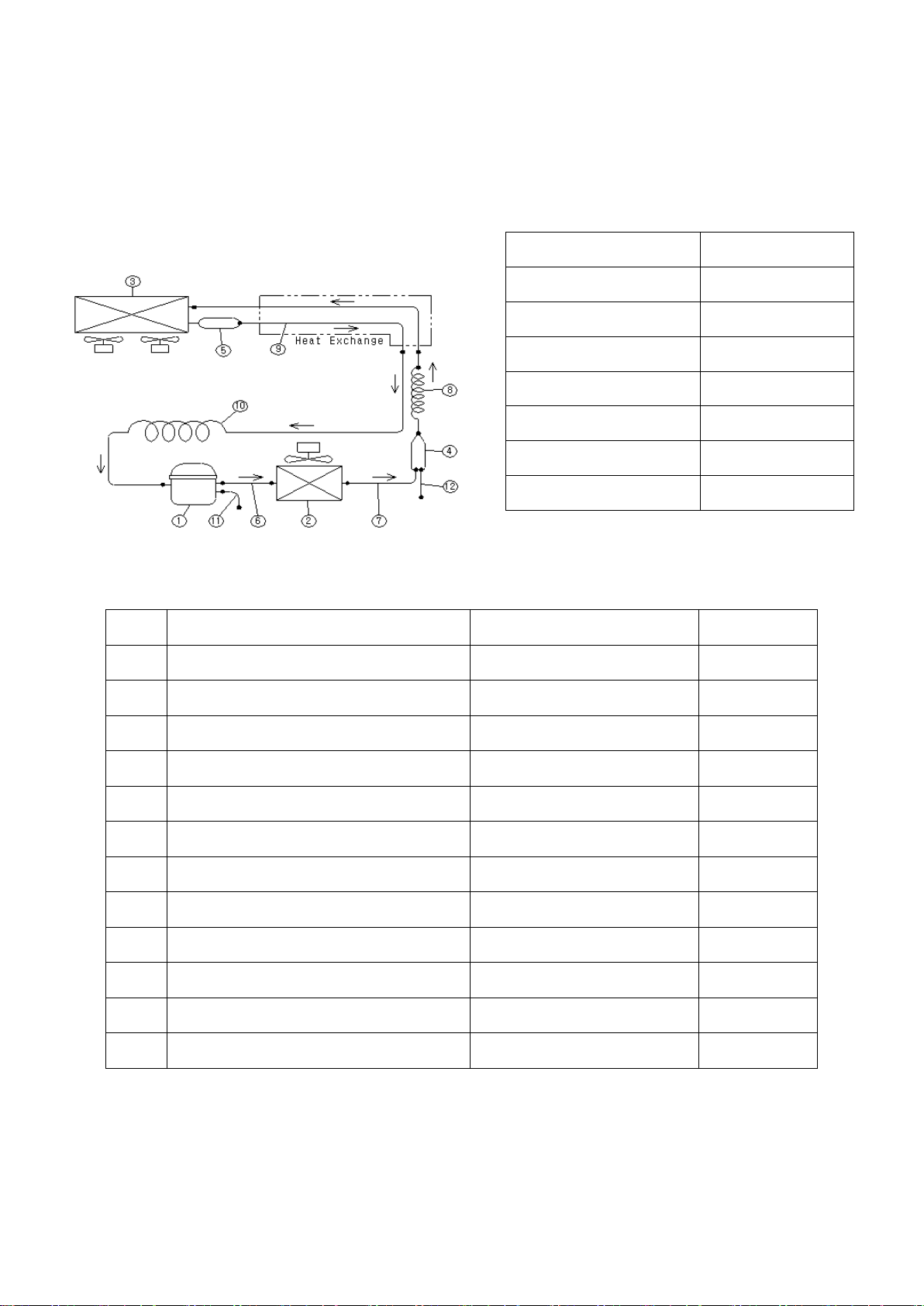
2. REFRIGERATION CYCLE
CONDENSER
EVAPORATOR
CAPILLARY TUBE
COMPRESSOR
Mechanical refrigeration is accomplished by continuously circulating, evaporating, and condensing a fixed
supply of refrigerant in a closed system. Evaporation occurs at allow temperature and pressure while
condensation occurs at high temperature and pressure. Thus it is possible to transfer heat fom an area of
low temperature (i.e., refrigerated compartment) to an area of high temperature (i.e., surrounding of
refrigerator).
THE BASE REFRIGERATION CYCLE
Beginning the cycle at the evaporator inlet the low pressure liquid expands, absorbs heat (so refrigerator
inner-cabinet is cooled), and evaporates, changing to allow low pressure gas at the evaporator outlet.
The compressor pumps this gas from the evaporator, increases its pressure, and discharges the high
pressured- temperature gas to the condenser.
The condenser lets high pressured- temperature gas emit the heat (so surrounding of the condenser is
warmed) in order to make it condense.
The capillary tube prevents high pressured- temperature liquid from entering the evaporator in order to
lower the pressure in the evaporator and control the flow of refrigerant into the evaporator automatically.
Eventually the desired air temperature in refrigerator inner-cabinet is reached, the thermostat (temperature
controller) will break the electrical circuit to the compressor motor and stop the compressor.
- 9 – 05/15 Rev. G 146526
Page 10
As the temperature of the air rises, the thermostat (or controller) remakes the electrical circuit. The
compressor starts, and cycle continues.
The schematic refrigeration (or freezing) cycle of F23/F49/F72/R23/R49/R72/GR26/GR48/GR70 is like
below.
MODEL COMPRESSOR
F23-S/SH, R49/R72-G NEK2150GK
F49-S/SH CAJ2432Z(A)
F72-S/SH CAJ2446Z(H)
R23/R49-S/SH,R23-G SK1A1C-L2W
R72-S/SH CAJ4461Y(A)
GR26H SK182C-L2U
GR48S, GR70H CAJ4476Y(A)
No. Part Name Description Remark
1 COMPRESSOR
2 CONDENSER C1220TS-O,H
3 EVAPORATOR C1220TS-O,H
4 DRYER C1220T-H
5 ACCUMULATOR C1220T-1/4H
6 DISCHARGE PI PE C1220T-O
7 DRYER CONNECT PIPE C1220T-O
8 CAPILLARY TUBE C1220T-H
9 SUCTION PIPE (INNER-CABINET) C1220T-O
10 SUCTION PIPE (COMPRESSOR) C1220T-O
11 CHARGE PIPE (COMPRESSOR) C1220T-O
12 CHARGE PIPE (DRYER) C1220T-O
- 10 – 05/15 Rev. G 146526
Page 11
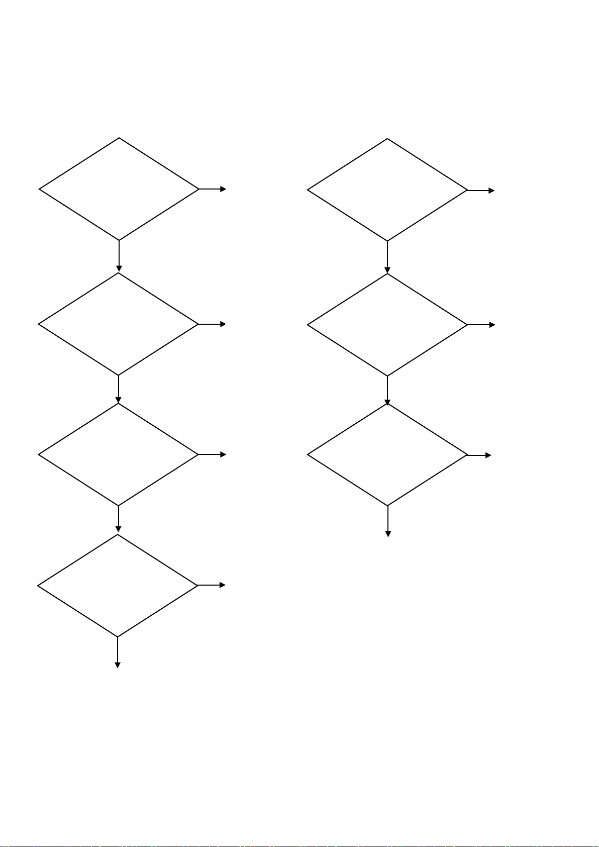
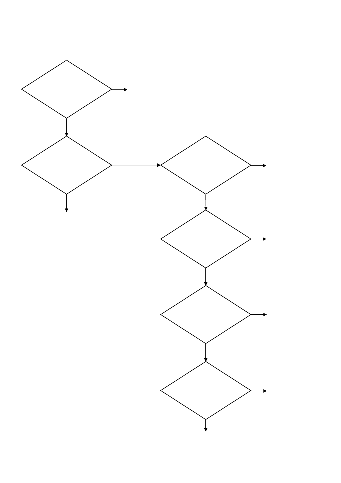
3. TROUBLESHOOTING
Is the rated voltage
NO
NO
NO
NO
NO
NO
NO
YES
YES
YES
YES
YES
YES
YES
Is the power cord
Is the power cord
Is the power switch
Is the power cord
Is the rated voltage
Is the power cord
Plug in
Plug in
Correct
Correct
Defective
Defective
power cord
NORMAL
NORMAL
Move to “ON” position
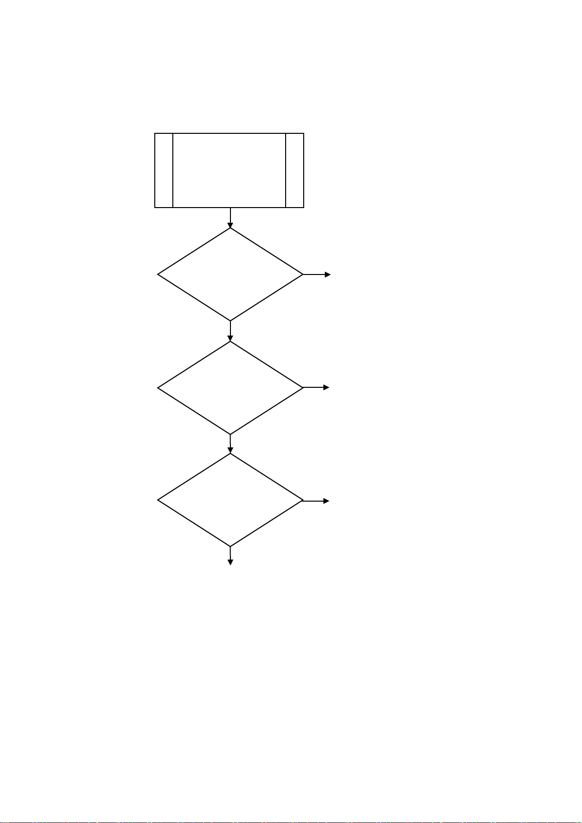
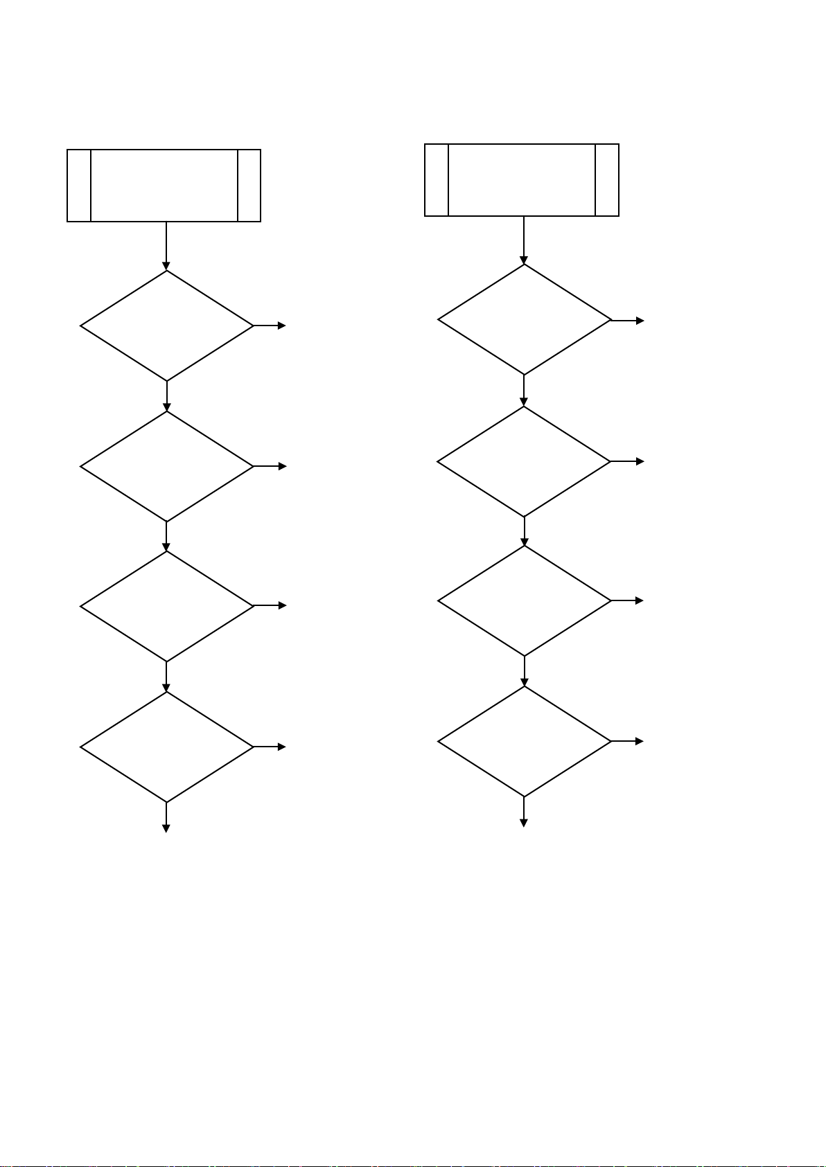
1) CHECKING THE P O WE R SUPP LY
① F23 / F49 / F72 / R23 / R49 / R72 ② GR26H / GR48S / GR70H
Plugged in?
supplied?
normal?
Plugged in?
supplied?
normal?
power cord
“OFF” position?
- 11 – 05/15 Rev. G 146526
Page 12
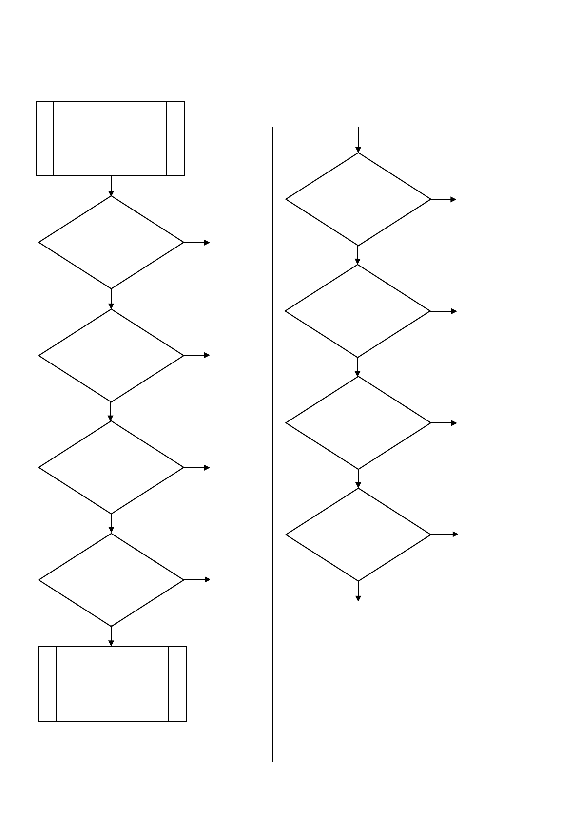
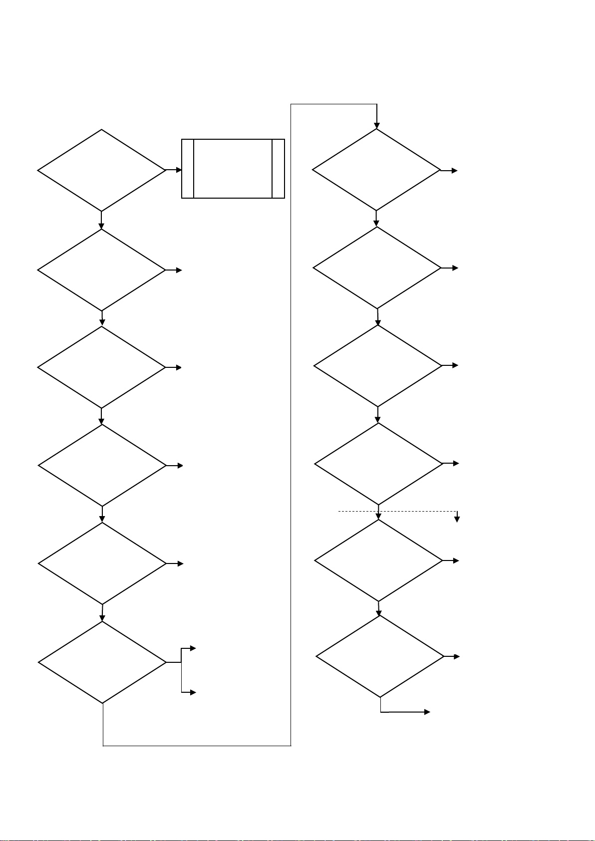
2) CHEKING THE POWER SUPPLY OF CONTROL BOARD
NO
YES
Is the rated
Check wirin g
NO
YES
NO
YES
Is the coil winding
open?
Defective
NO
YES
Is the secon dary
normal
NO
YES
Is the DC 24V
Check C/B
NO
YES
Does the contact
continue?
Defective
Defective fuse
Defective
NORMAL
① F23 / F49 / F72 / R23 / R49 / R72
voltage supplied
to the C/B?
Does the fuse f ail?
of transformer
output volt, of trans,
transformer
transformer
NOTES
* C/B: Control Board
(Printed Circuit Board)
* Fuse Spec: AC250V, 8A
* Trans forme r Spec.
Primary: AC1 15V
Secondary: AC12V (Red wire)
AC20V (Blue wire)
supplied to c oil part
in relay?
part in relay
Relay
- 12 – 05/15 Rev. G 146526
Page 13
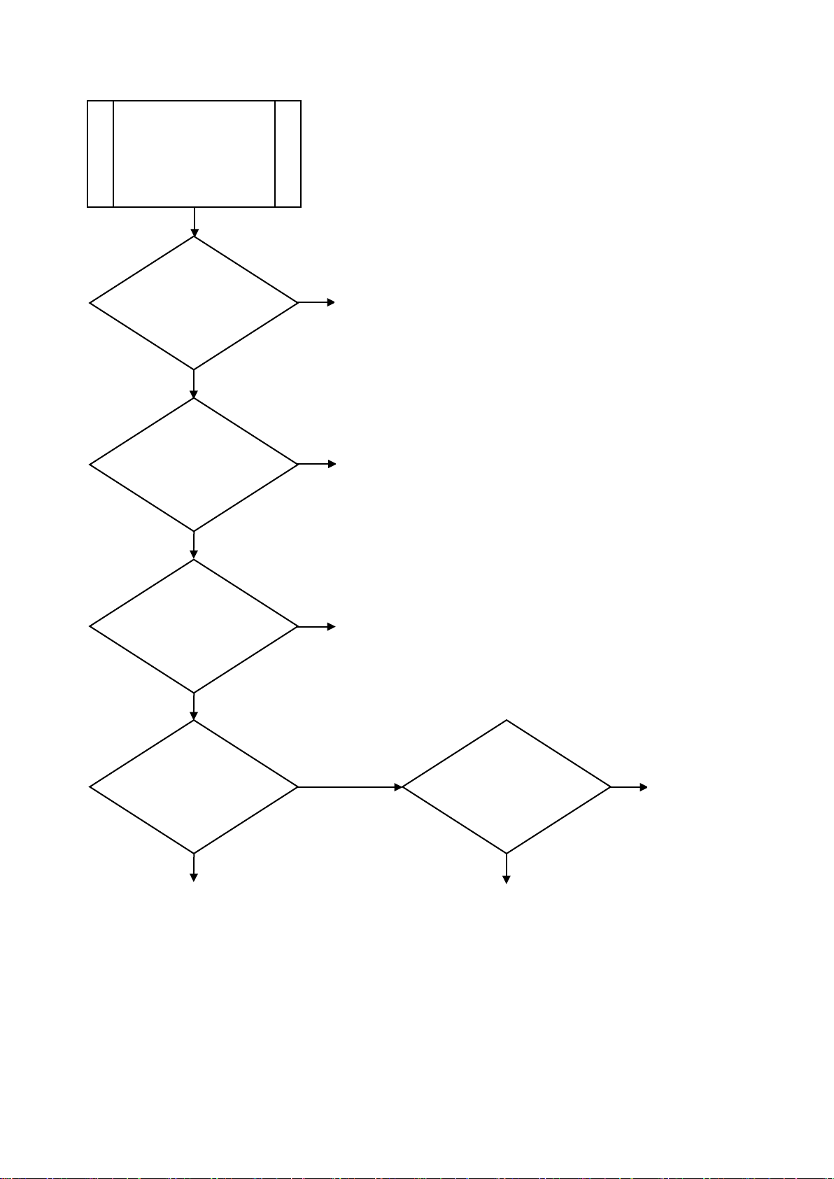
3) CHECKING THE CONTROL PART OF REFRIGERATION CYCLE
NO
YES
NO
YES
NO
YES
Check the
in compress or
Defective
OLP
NO
YES
Check the
in compress or
Defective
relay
NO
YES
Are the sens ors in
properly?
NO
YES
Defective
T-sensor
NO
YES
Is the tem p.
properly?
Defective
MICOM
NO
YES
Check the
point
Temperature
Check the
control board
① F23 / F49 / F72 / R23 / R49 / R72
Check the
power supply
Is the to comp.
connected pro per ly?
Are the relay
& OLP in comp.
assembled properly?
continuity of OLP
Correct
Correct
C/B connected
Check the re sistance
of T-Sensor
displayed i n D/B
Correct
continuity of relay
power supply of
temperature set
resetting
Defective compressor
NOTES
* C/B: Control Board
* D/B: Display Board
* OLP: Over load Protector
- 13 – 05/15 Rev. G 146526
Page 14
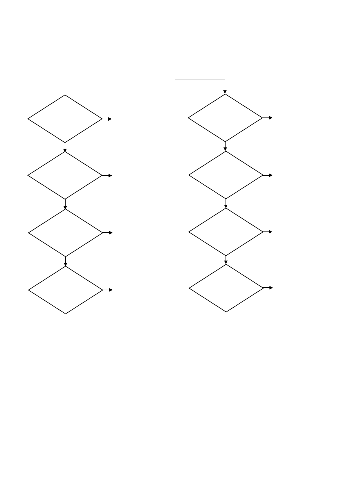
② GR26H / GR48S / GR70H
NO
YES
When the
run?
Defective
thermostat
NO
YES
Is the to comp.
NO
YES
Are the relay
NO
YES
Check the
in compress or
Defective compressor
NO
YES
Check the
in compress or
Defective
relay
Defective OLP
Check the
power supply
thermostat is OF F.
Does the comp.
connected pro per ly?
& OLP in comp.
assembled properly?
continuity of OLP
Correct
Correct
continuity of relay
- 14 – 05/15 Rev. G 146526
Page 15
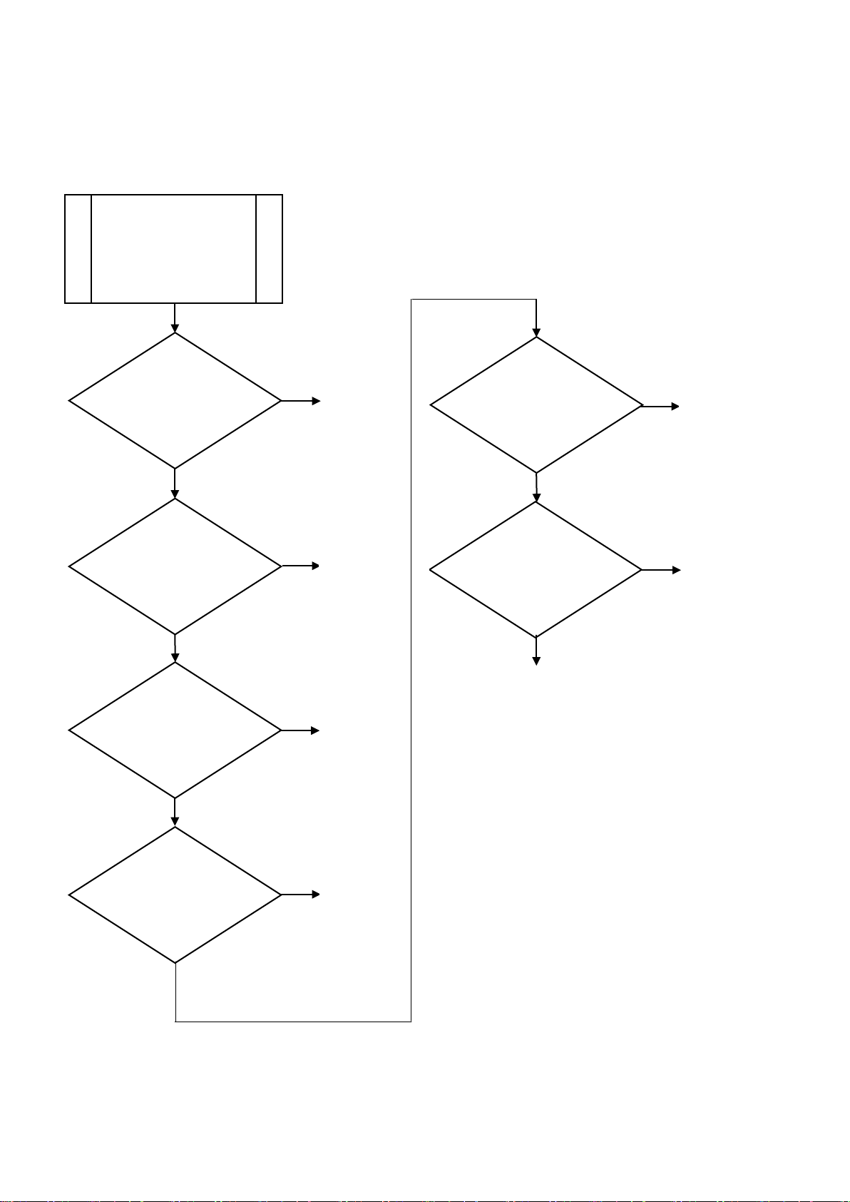
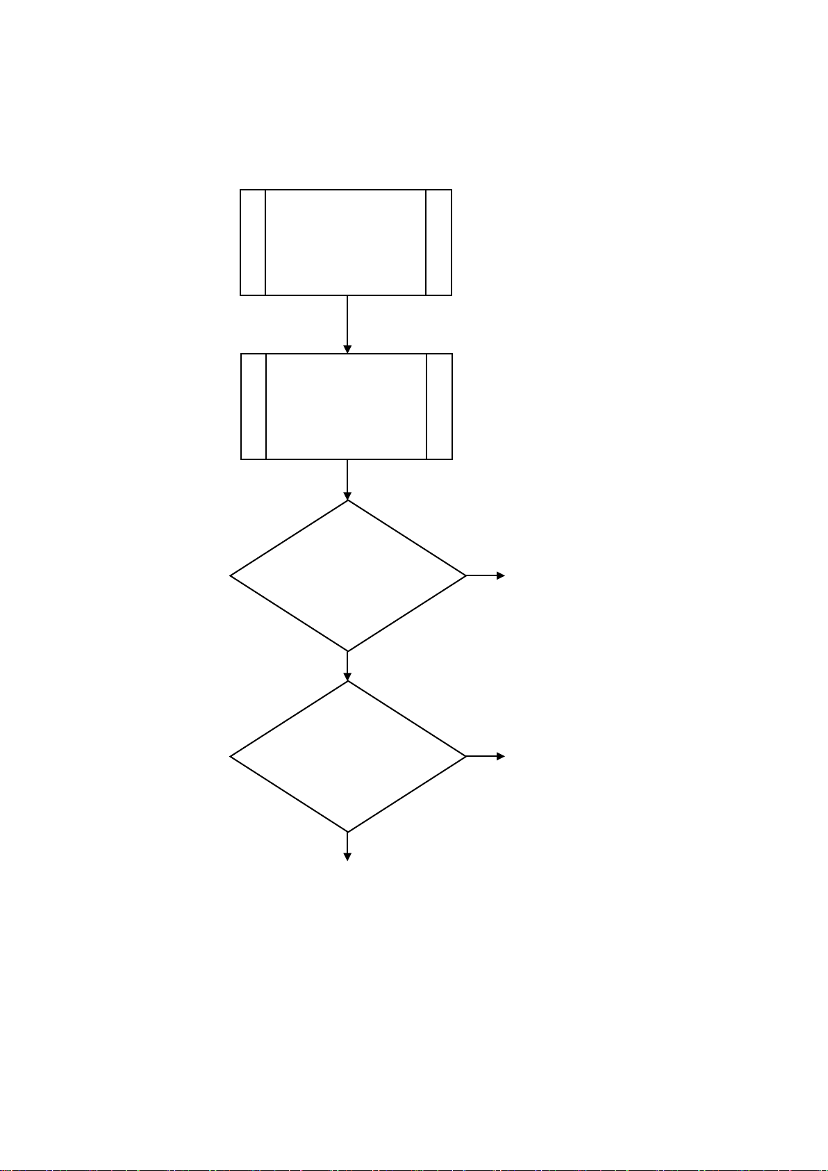
4) CHECKING THE DEFROST PART
NO
NO
YES
NO
YES
Defective
D-Sensor
NO
YES
Defective
NO
Does the B/M
NO
YES
Defective
Control Board
Check
Defective
YES
YES
① F23 / F49 / F72
Check the
power supply
Do the B/M and D-
Sensor located in
place?
Do the wiring to the
heater and B/M
connected properly?
Check the
resistance of
D-sensor
Correct
wiring
continue below
41℉(5℃)
Dose the defrost
output on C/B normal
in defrost mode?
Defective MICOM
Bi-Metal
Are the defrost
heaters normal?
NOTES
* C/B: Control Board
heater
* B/M: Bi-Metal
(Temp. Limiting Controller)
- 15 – 05/15 Rev. G 146526
Page 16
② R23 / R49 / R72
NO
YES
NO
NO
YES
Defective
D-Sensor
Defective
Control Board
Defective micom
YES
Check the
power supply
Do the D-Sensor
located in place ?
Check the
resistance of
D-sensor
Dose the defrost
output on C/B normal
in defrost mode?
Correct
NOTES
* C/B: Control Board
- 16 – 05/15 Rev. G 146526
Page 17
5) WHEN THE UNIT DOES NOT COOL
Apply spacer
YES
Does the
NO
YES
Is the unit
NO
YES
NO
YES
NO
YES
NO
YES
NO
YES
NO
Does the cond.
YES
NO
NO
YES
Is the
NO
YES
YES
NO
YES
NO
Freezer: Check
Refrigerator:
Excluding GR26H, GR48S
Defective
door switch
Check compressor
① All Models
compressor run
normally?
located in a
level place?
Is the temperature
set point proper?
Check
the control part of
refrigeration cycle
Correct
Temperature
resetting
Is there
dust on condenser
fin?
(eva.) fan motor rotate
normally?
Does the
refrigerant leak?
Clean
Defective
motor, fan
Correct
Are the goods
loaded properly?
Does the cool air
leak?
Does the frost
form excessively
in evaporator?
Correct
Check
door gasket
the defrost part
forced defrost
refrigerant line
restricted?
Is the contact of
door switch normal?
When door closed.
Are the door S/We pushed
by the top of door?
Correct
between door switch
and the top of door
- 17 – 05/15 Rev. G 146526
Page 18
6) WHEN THERE IS A ABNORMAL NOISE
Is the unit
NO
YES
NO
YES
NO
YES
Reform to
NO
YES
YES
NO
NO
YES
NO
YES
Comp. is running
not cool
YES
Defective
Defective
Defective
① All Models
located in a
level place?
Is the high
voltage supplied?
Are the pipes
rattled?
Are the parts
assembled tightly?
Correct
Adjust
voltage
be free of
contact
Tighten
Are the fans bent?
Do the fans
rotate well?
Is there any
noise in motor?
but the unit does
fan
fan, motor
motor
- 18 – 05/15 Rev. G 146526
Page 19
NO
YES
Is the connect ion
Check the
in control b oard
NO
YES
7) WHEN THE TEMPERATURE DOES NOT DISPLAY
① F23 / F49 / F72 / R23 / R49 / R72
Check the
power supply
power supply
between C/B and D/B
properly?
Is the micom
inserted on C /B
properly?
Replace display board
NOTES
* C/B: Control Board
Tighten
Tighten
* D/B: Display Board
- 19 – 05/15 Rev. G 146526
Page 20
8) WHEN THE LAMP DOES NOT LIGHT
Adjust the lamp
YES
Check the
Check the
with socket
Defective
NO
YES
Is the lamp
Defective
NO
YES
Check the
lamp switch
NO
YES
Check wiring
* Incandescence Lamp: 40W
Adjust the lamp
NO
YES
Check the
Check the
with socket
Defective
NO
YES
Is the lamp
Defective
lamp switch
NO
YES
Check the
lamp switch
Defective
ballast
NO
YES
Check wiring
* Fluorescent Lamp: 32W
① F23 / F49 / F72 / R23 / R49 / R72 ② GR26H / GR48S / GR70H
power supply
connecting points
defective?
for good connection
lamp
power supply
connecting points
defective?
for good connection
lamp
continuity of
When door closed.
Are the door S/We pushed
by the top of door?
lamp switch
Apply spacer
between door switch
and the top of door
continuity of
Check the
continuity of
ballast
- 20 – 05/15 Rev. G 146526
Page 21
9) CHECKING SENSOR
Sensor assembly consists of T-sensor (lead wire: orange) and D-sensor (lead wire: blue).
The T-s ensor is used for cabinet temperature control and the D-sensor is used for defrost control.
The resistance of the sensor varies depending on temperature.
If you Immerse the sensor in a glass containing ice water for 2 minutes and then check for the resistance
between sensor leads, the normal reading is 7.88 ㏀ (T-sensor) / 30 ㏀ (D-sensor).
Resistance (㏀)
Temperature (℉/℃)
T-sensor (±6.5%) D-sensor (±5.5%)
-5 / -21 23.04 79.17
0 / -18 19.76 68.92
10 / -12 14.65 52.61
23 / -5 10.10 37.55
32 / 0 7.88 30.00
41 / 5 6.20 24.13
50 / 10 7.91 19.53
60 / 16 3.82 15.56
70 / 21 3.00 12.48
- 21 – 05/15 Rev. G 146526
Page 22
4. FEATURE CHART
1) F23/R23-S
2) F49/R49-S
- 22 – 05/15 Rev. G 146526
Page 23
3) F72/R72-S
4) F23/R23-SH
- 23 – 05/15 Rev. G 146526
Page 24
5) F49/R49-SH
6) F72/R72-SH
- 24 – 05/15 Rev. G 146526
Page 25
7) R23-G
8) R49-G
- 25 – 05/15 Rev. G 146526
Page 26
9) R72-G
DOOR HANDLE
CONDENSER
COMPRESSOR
EVAPORATOR
SHELF
SHELF SUPPORT
DRAIN HOSE
FAN COVER
WATER COLLECTOR
LAMP
DOOR FRAME
AD. PANEL
DRYER
CONDENSER FAN MOTOR
COOLING FAN
COOLING FAN MOTOR
SUCTION PIPE
BALLAST
LOWER GRILLE
MOTOR BRKT
LAMP
COVER LAMP
AD. Panel
Door (Glass)
Lower grille
Adjust foot
Door handle
[ Front view ]
[ Side view ]
10) GR26H
- 26 – 05/15 Rev. G 146526
Page 27
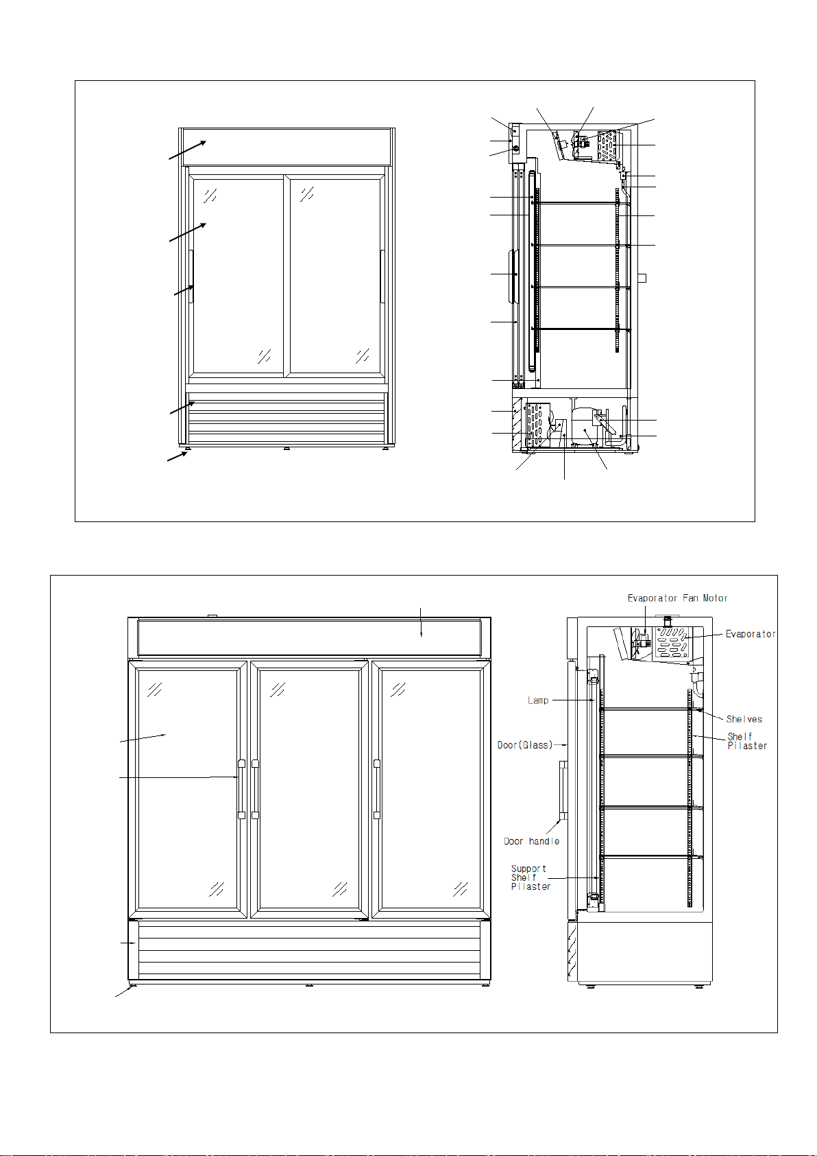
11) GR48S
Door(Glass)
Door handle
Adjust foot
Lower grille
AD. Panel
[ Front view ]
[ Side view ]
EVAPORATOR
COOLING FAN
COOLING FAN MOTOR
BALLAST
AD. PANEL
WATER COLLECTOR
DRAIN HOSE
SHELF SUPPORT
SHELF
CONDENSER
LOWER GRILL
DOOR HANDLE
DOOR FRAME
COMPRESSOR
SUCTION PIPE
COOLING FAN COVER
LAMP
LAMP TUBE
DRIER
CONDENSER FAN MOTOR
MOTOR BRKT
CENTER POST
LAMP
AD. Panel
Door (Glass)
Lower grille
Adjust foot
Door handle
[ Front view ]
[ Side view ]
12) GR70H
- 27 – 05/15 Rev. G 146526
Page 28

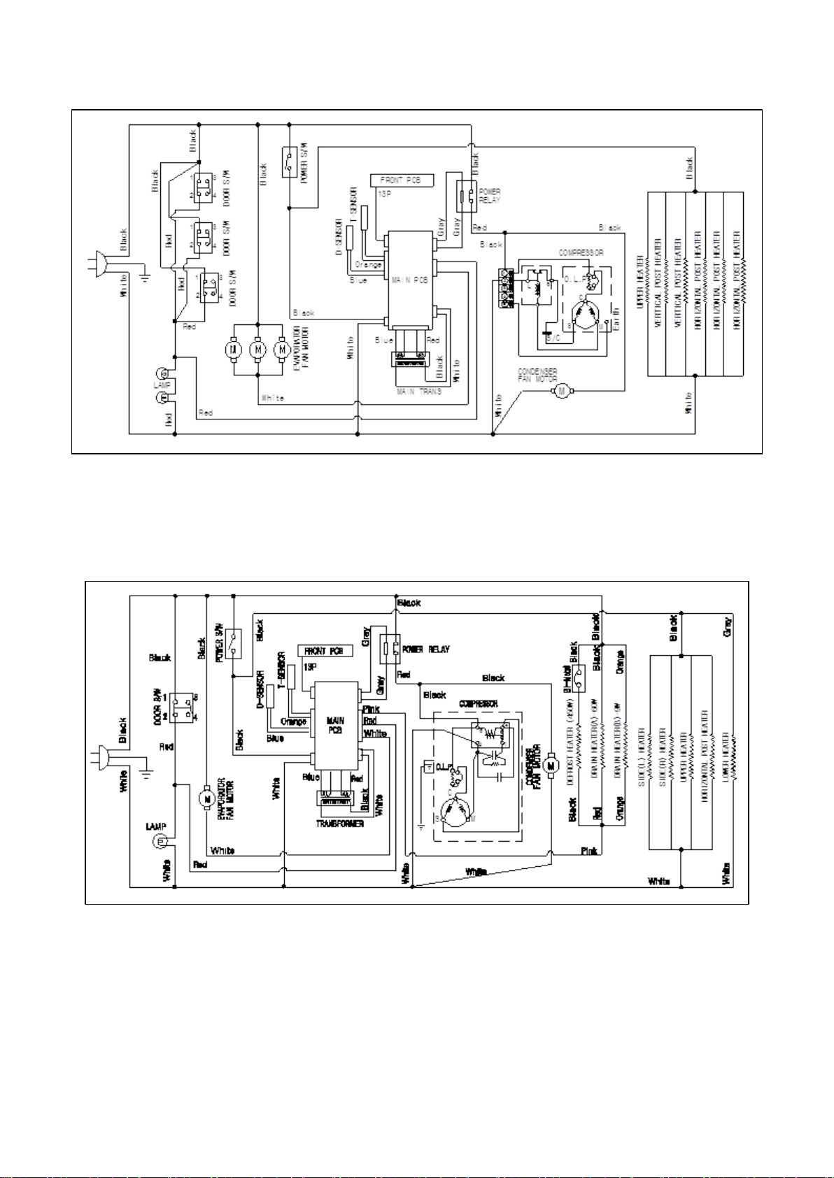
5. WIRING DIAGRAMS
1) F23-S
2) F49-S
- 28 – 05/15 Rev. G 146526
Page 29

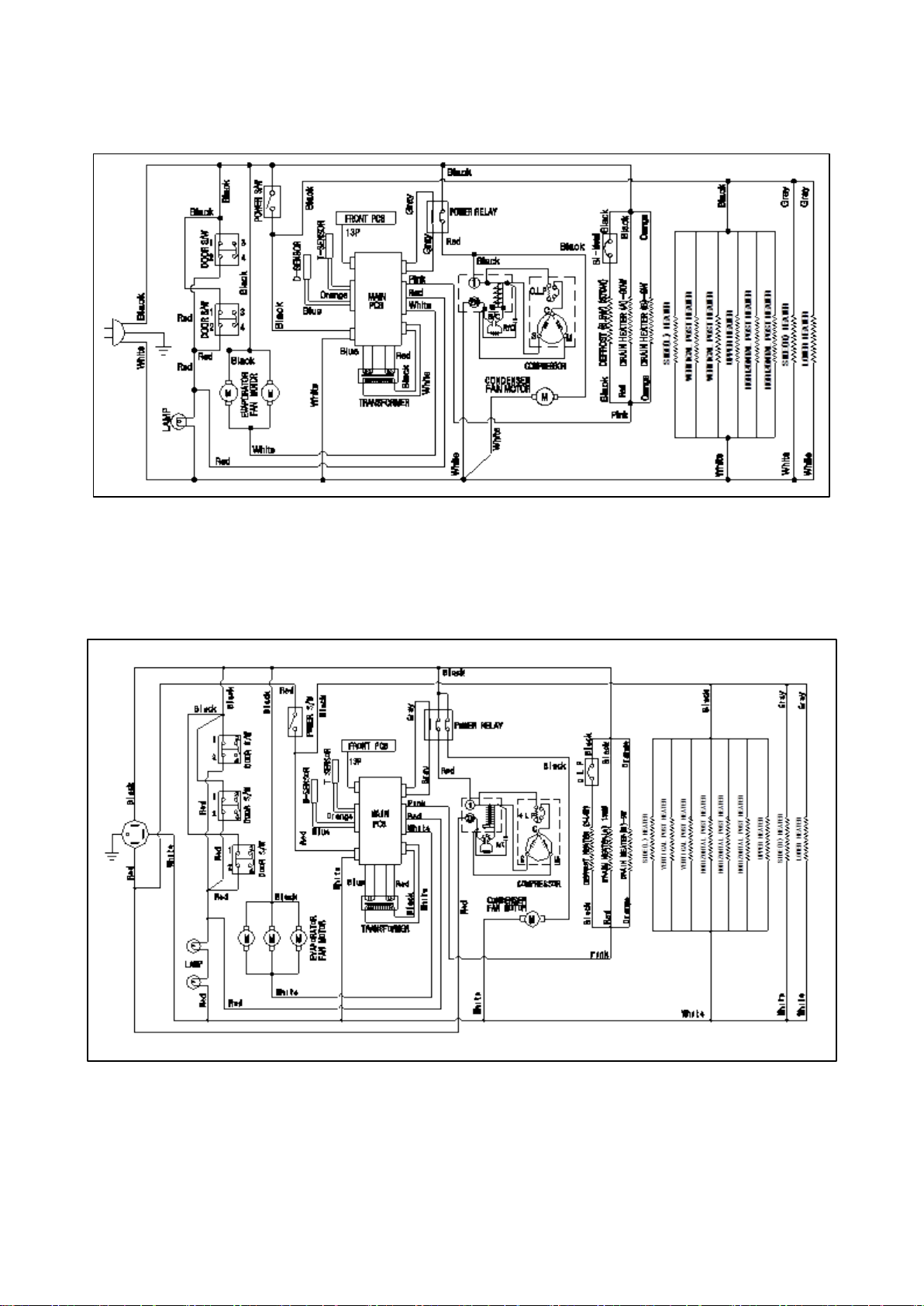
3) F72-S
4) R23-S
- 29 – 05/15 Rev. G 146526
Page 30

5) R49-S
6) R72-S
- 30 – 05/15 Rev. G 146526
Page 31

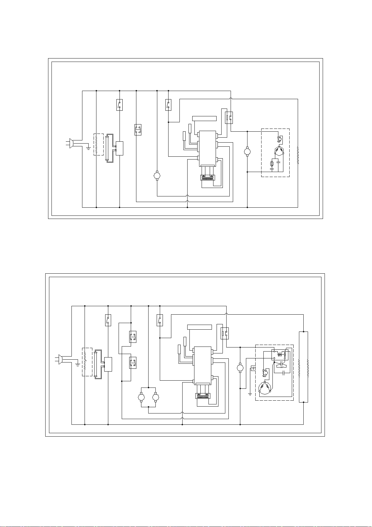
7) R23-SH
8) R49-SH
- 31 – 05/15 Rev. G 146526
Page 32
9) R72-SH
10) F23-SH
- 32 – 05/15 Rev. G 146526
Page 33
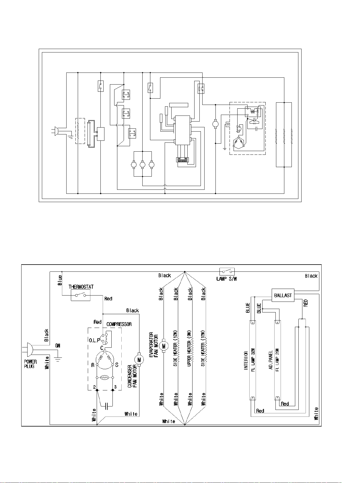
11) F49-SH
12) F72-SH
- 33 – 05/15 Rev. G 146526
Page 34
COMPRESSOR: SK1A1C-L2W
MODEL : R23-G ( REFRI GERATOR)
P OWE R
M
F RON T P CB
13P
T-SENSOR
D-SENSOR
MA I N
PCB
MAI N TRANS
M
1
2
3
4
Bl u e
Or a n g e
Gr a y
Red
Bl u e
COMP RE SS OR
DOOR S / W
UPPER HEATER
Bl a ck
Wh i t e
Bl a ckRed
E V A POR AT OR
F A N MOT OR
Bl a ck
P O WE R S / W
Wh i t e
Bl a ck
Bl a ck
Wh i t e
Bl a ck
Red
Gr a y
REL AY
M
C
O.L.P
S
CR
CS
Bl a ck
Bl a ck
Wh i t e
COND E NS OR
F A N MOT OR
Bl a ck
Wh i t e
DOOR HE A T E R
L I GHT S/ W
S.M.P.S
LED
( opt i on)
Wh i t e
P OWE R
M
F RON T P C B
13P
T-SENSOR
D-SENSOR
MA I N
PCB
MA I N T R A N S
M
1
2
3
4
Bl u e
Or a n g e
Gr a y
Red
Bl u e
DOOR S / W
Bl a ck
Wh i t e
Bl a ck
Red
E V A P ORA TOR
F A N MOT OR
Bl a ck
P O WE R S / W
Wh i t e
Bl a ck
Bl a ck
Wh i t e
Bl a ck
Red
Gr a y
REL AY
Bl a ck
Wh i t e
COND E NS OR
F A N MOT OR
1
2
3
4
DOOR S / W
Bl a ck
Red
M
UPPER HEATER
Wh i t e
P OST HEA T ER
Bl a ck
5
2
4
1
S
M
C
COMPRESSOR
O.L.P
DOOR HEATER× 2EA
L I GHT S/ W
S.M.P.S
LED× 2EA
Bl a ck
( Op t i o n )
COMPRESSOR: NEK2150GK
MODEL : R49 -G ( REFRI GERAT OR)
Wh i t e
Red
13) R23-G
6) R49-G
- 34 – 05/15 Rev. G 146526
Page 35
Bl u e
F R ONT P C B
DOOR S / W
1
3
Bl a ck
M
Wh i t e
Red
Red
2
F A N MOT OR
E V A P OR AT OR
P O WE R S / W
Wh i t e
Bl a ck
4
2
1
Bl a ck
Bl a ck
DOOR S / W
4
3
13P
PCB
UPPER HEATER
Bl a ck
Wh i t e
Red
Wh i t e
POWER RE LA Y
MA I N
Gr a y
Red
Gr a y
Bl a ck
Bl a ck
Bl a ck
P OS T HE A T E R
P OS T HE A T E R
M M
2
1
4
3
DOOR S / W
Bl a ck
Red
M
Bl a ck
Wh i t e
CON DE NS OR
F A N MOT OR
5
2
4
1
S
M
C
COMPRESSOR
O.L.P
Bl a ck
DOOR HEATER× 3 EA
L I GHT S/ W
S.M.P.S
LED× 3EA
T-SENSOR
D-SENSOR
Bl u e
Or a n g e
( opt i on)
COMPRESSOR: NEK2150GK
MODEL : R72 -G ( REFRI GERAT OR)
Wh i t e
Red
MA I N T R A NS
6) R72-G
7) GR26H
- 35 – 05/15 Rev. G 146526
Page 36
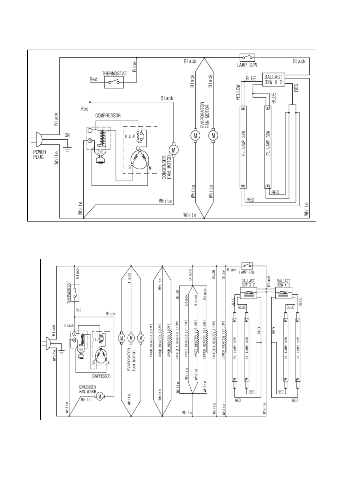
8) GR48S
9) GR70H
- 36 – 05/15 Rev. G 146526
Page 37
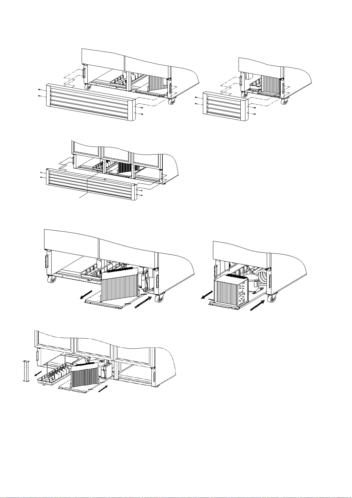
6. REPLACEMENT OF COMPONENTS
※
Disassemble
a) Separate the compressor harness out of
a) Unplug the power cord before service.
1) CONDENSING UNIT
(F49/F72/R49/R72) (F23/R23/GR26H)
b) Remove screw securing the lower grille.
* Remove screw securing the reinforce
angle.(GR48S/GR70H)
(GR48S/GR70H)
(F49/F72/R49/R72) (F23/R23/GR26H)
the terminal block.
b) Remove screws securing the unit base
plate and pull out condensing unit with care.
c) Replace the necessary com-ponent.
(GR48S/GR70H)
CAUTION
1. Please pull out or push in the unit base plate carefully to prevent capillary tube, pipes and wires
from damaging.
2. It is recommend to arrange wires after you push in the unit base plate.
- 37 – 05/15 Rev. G 146526
Page 38
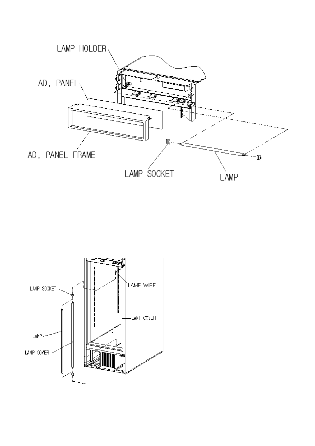
2-1) LAMP (GR26H)
a) Unplug the power cord before
a) Unplug the power cord before service.
b) Remove screw securing the Ad. Panel Frame and pull out the Ad. Panel Frame with care.
c) Separate the Ad. Panel.
d) Separate the Lamp from the Lamp Holder.
e) Separate the Lamp Socket and replace the Lamp with care.
service.
♠ Lamp Description: AC115V, F17T8/TL950
b) Separate the Lamp from the
Lamp Holder.
c) Separate the Lamp Socket and
the Lamp wire.
d) Replace the Lamp with care.
- 38 – 05/15 Rev. G 146526
Page 39
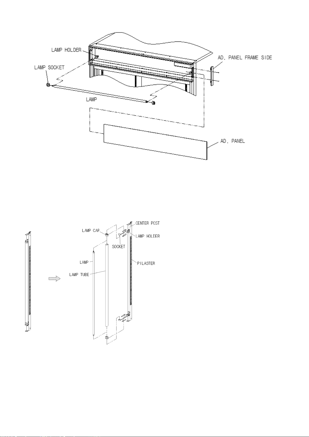
2-2) LAMP (GR48S)
a) Unplug the power cord before service.
a) Unplug the power cord before service.
b) Remove screw securing the Ad. Panel Side.
c) Separate the Ad. Panel.
d) Separate the Lamp from the Lamp Holder.
e) Separate the Lamp Socket and replace the Lamp with care.
b) Separate the Lamp from the
Lamp Holder.
c) Separate the Lamp Socket and
the Lamp wire.
♠ Lamp Description: AC115V, FHF32SSEX-D-5
d) Replace the Lamp with care
.
- 39 – 05/15 Rev. G 146526
Page 40
a) Unplug the power cord before service.
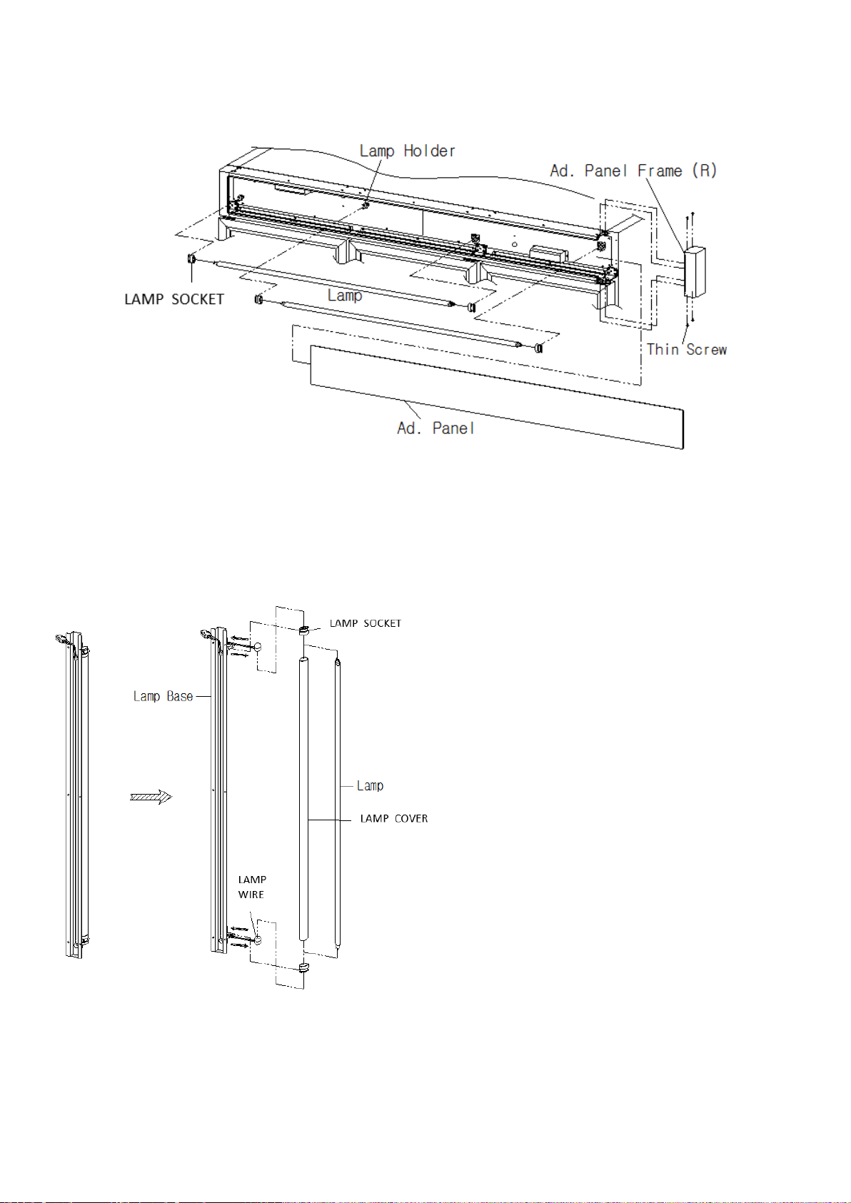
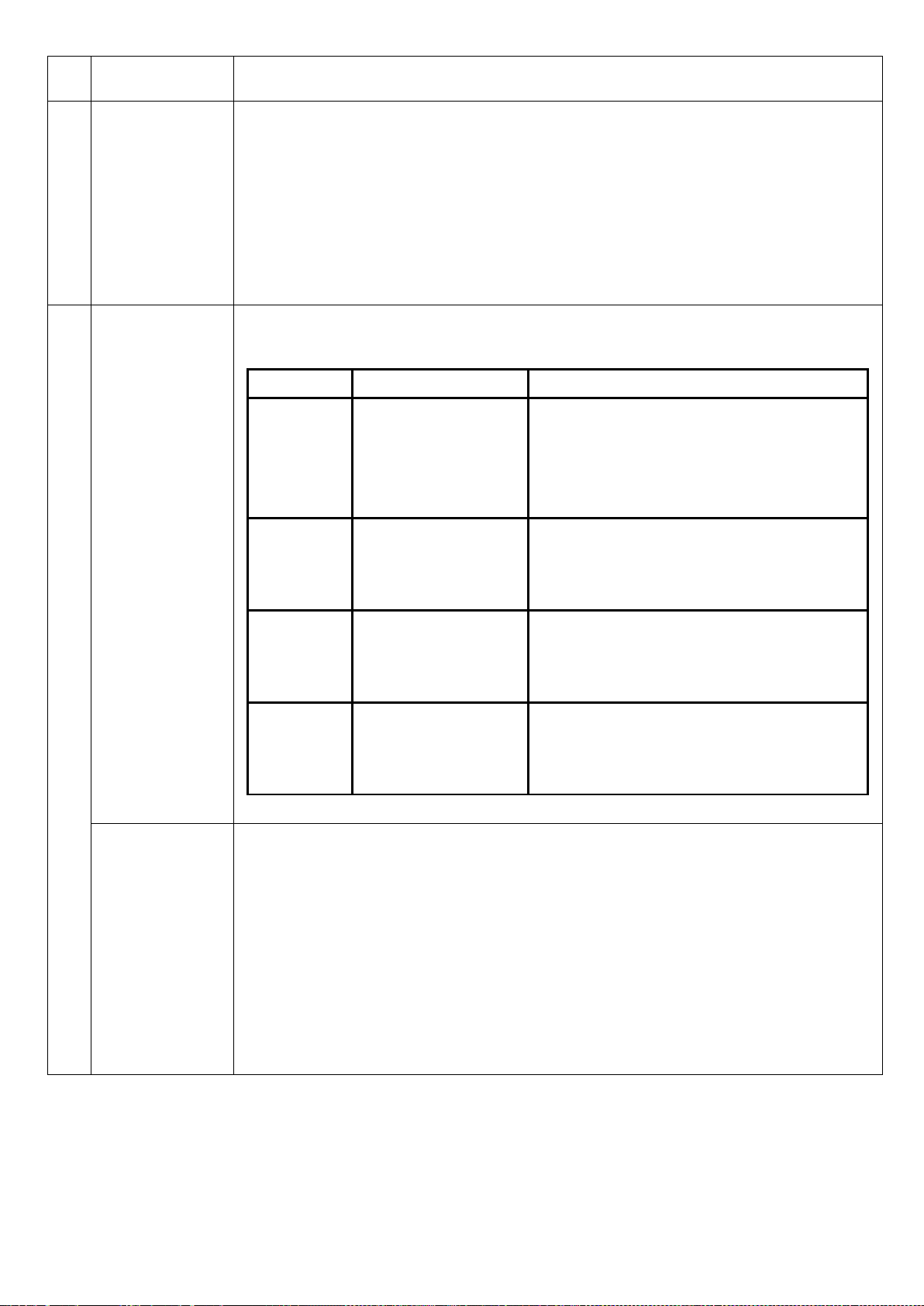
2-3) LAMP (GR70H)
a) Unplug the power cord before service.
b) Remove screw securing the Ad. Panel Frame (R).
c) Separate the Ad. Panel.
d) Separate the Lamp from the Lamp Holder.
e) Separate the Lamp socket and replace the Lamp with care.
b) Separate the Lamp from the Lamp Holder.
♠ Lamp Description: AC115V, 32W, F32T8/TL860
c) Separate the Lamp Socket and the
Lamp wire.
d) Replace the Lamp with care.
- 40 – 05/15 Rev. G 146526
Page 41

B. OPERATION AND ELECTRONIC CONTROLLER
FUNCTION
1. OPERATION FOR F23, F49, F72, R23, R49, R72 MODELS - - - - - B2
1) BASIC OPERATION
2) ELECTRONIC CONTROLLER SETTING MODE
3) NORMAL CONTROL PROCESS
4) ERROR CO DE
2. OPERATION FOR GR26H, GR48S, GR70H MODELS - - - - - - - - - B12
1) BASIC OPERATION
2) DEFROST
3) CONTROL TEMPERATURE
4) LAMP
3. INSTRUCTION FOR RE-HINGING DOOR - - - - - - - - - - - - - - - - - B13
- 41 – 05/15 Rev. G 146526
Page 42

1. OPERATION FOR F23/F49/F72(FREEZER), R23/R49/R72(REFRIGERATOR)
1) BASIC OPERATION
① Plug in the power cord and turn on the power switch located on the bottom of the top grille right side.
[ The unit should be plugged into a 115V±10%, 60Hz (F23, F49, R23, R49, R72 models) ]
[ The unit should be plugged into a 115V/208~230V, 60Hz (F72 model) ]
② Display panel will be lit for 2 seconds with buzzer then displays cabinet interior
temperature (T-sensor) and running conditions.
* Freezer : If cabinet interior temperature is higher than 14℉ (-10℃) compressor will run without
delay, and lower than 14℉ (-10℃), compressor will run after 3 minutes.
* Refrigerator : If cabinet interior temperature is higher than 50℉ (10℃) compressor will run
without delay, and lower than 50℉ (10℃), compressor will run after 3 minutes.
③ The default OPERATING TEMPERATURE SETTING
* Freezer :Temperature set point (setting mode sign [St]) is –5℉ (-20℃)
Temperature differential set point (setting mode sign [di]) is 8℉ (4℃)
Range of adjustable set point: -22℉~ 8℉(-30℃ ~ -10℃)
* Refrigerator : Temperature set point (setting mode sign [St]) is 36℉ (4℃) in solid door refrigerator
Temperature set point (setting mode sign [St]) is 35℉ (4℃) in glass door refrigerator
Temperature differential set point (setting mode sign [di]) is 8℉ (4℃)
Range of adjustable set point: 25℉~ 50℉ (2℃ ~10℃)
④ Defrost frequency
* Freezer : It is controlled by MICOM and the default defrost frequency is 6 hours.
* Refrigerator : It is controlled by MICOM and the default defrost frequency is 12 hours.
⑤ The light inside the cabinet comes on when the door is opened in Solid Door models
while light is always on in Glass Door models.
The cabinet interior cooling fan has 3 seconds delay when the door is closed.
When CO MP . is OFF, EVA. fan repeats ON and OFF according to setting times
If door is opened , EVA. fan OFF and then closed the door, EVA. fan repeats ON and OFF according
to setting times
- 42 – 05/15 Rev. G 146526
Page 43

⑥ If door is opened, door open warning sign (LED) will turn on.
If door is opened more than 30 seconds, the sound alarm beeps 3 times,
if open more than 60 seconds, the sound alarm beeps 5 times and if open more than 5 minutes,
the sound alarm will beep continuously.
⑦ Cabinet interior temperature
* Freezer : If it is higher than 14℉ (-5℃), the panel displays [Hi] and
lower than -50℉ (-40℃), the panel displays [Lo].
* Refrigerator : If it is higher than 68℉ (15℃), the panel displays [Hi] and
lower than 14℉ (-2℃), the panel displays [Lo].
- 43 – 05/15 Rev. G 146526
Page 44

2) ELECTRONIC CONTROLLER SETTI NG MODE
Display Description
St Temperature Setting Mode
di Temper ature Differential Setting Mode
th Cabinet Temperature Verification Mode
dt Def r ost Frequency Setting Mode
tb Rapid Freeze Mode (Freezer Only)
dF For c ed Defrost Mode
SE T emperatur e Unit Converter mode(℉↔℃)
※ In converting Temperature Unit (℉↔℃), 1℉ (1℃) deviation can occur.
- 44 – 05/15 Rev. G 146526
Page 45

No Setting Mode
until the desired
℉~16℉(2℃~10℃
℉~16℉(2℃~10℃
Mode
Sign
How to Setting
1.To enter this mode, press [MODE/SET] and [UP or DOWN]
simultaneously until [St] is displayed.
2. Then press [MODE/SET] to see current temperature set point.
3. To change the set point, press [UP or DOWN]
value is displayed.
4. At the end of the sequence, press [MODE/SET] to set the value.
1
Temperature
Setting
Mode
“St”
5. To display the cabinet temperature again, press [UP or DOWN]
until [th] is displayed and then press [VERIFY].
6. Range of adjustable set point : -22℉~8℉(-30℃~ -10℃) (Freezer)
Range of adjustable set point : 25℉~50℉(2℃ ~ 10℃) (Refrigerator)
1. To enter this mode, press [MODE/SET] and [UP or DOWN]
simultaneously until [di] is displayed.
2. Then press [MODE/SET] t o see current temperature differential.
3. To change the set point, press [UP or DOWN] until the desired
value is displayed.
4. At the end of the sequence, press [MODE/SET] to set the value.
Temperature
Differential
2
Setting
Mode
5. To display the cabinet temperature again, press [UP or DOWN]
until [th] is displayed and then press [VERIFY].
“di”
6. Range of adjustable set point : 4
Range of adjustable set point : 4
(The Unit of Setting : 2℉(2℃))
) (Freezer)
) (Refrigerator)
- 45 – 05/15 Rev. G 146526
Page 46

No Setting Mode
1. To enter this mode, press [MODE/SET] and [UP or DOWN]
is displayed instead of the cabinet
1. To enter this mode, press [MODE/SET] and [UP or DOWN]
to start rapid
is displayed instead of the cabinet
Defrost
Frequency
3
Setting
Mode
Mode
Sign
“dt”
How to Setting
1. To enter this mode, press [MODE/SET] and [UP or DOWN]
simultaneously until [dt] is displayed.
2. Then press [MODE/SET] to see current defrost frequency.
3. To change the defrost frequency, press [UP or DOWN] unt il the
desired value is displayed.
4. A t th e end of the sequence, press [MODE/SET] to set the value.
5. To display the cabinet temperature again, press [UP or DO WN]
until [th] is displayed and then press [VERIFY].
6. Range of adjustable defrost frequency : 4Hr to 12Hr
(The Unit of frequency : 2Hr)
Forced Defrost
4
Cancelation
5
Forced Defrost
Rapid Freeze
6
(Freezer)
Mode
of
Mode
Mode
“dF”
Flash
"dF"
"tb"
simultaneously until [dF] is displayed.
2. Then press [M AN UA L DF ] m ore than 2 seconds to start f orced
defrost.
3. During defrosting, [dF]
temperature.
1. During forced defrost, press [M ANUAL DF] more than
2 seconds to stop forced defrost.
2. The [dF] will be flash 5 times and then return to normal
display mode.
simultaneously until [tb] is displayed.
2. Then press [MODE/SET] more than 2 seconds
freeze mode.
3. During rapid freeze, [tb]
temperature.
- 46 – 05/15 Rev. G 146526
Page 47

3) NORMAL CONTROL PROCESS
1. Compressor and condenser fan motor is controlled by T-sensor and MICOM
No FUNCTION FUNC TION SPEC
1. After Power ON, Display panel will be lightened for 2 seconds with buzzer then
displays cabinet interior temperature.
1
2
Initial
Operating
Normal
Operating
2. If cabinet interior temperature is higher than 14℉(-10℃) Freezer or 50℉(10℃)
Refrigerator, compressor will run without delay, and lower than 14℉(-10℃)
Freezer or 50℉(10℃) Refrigerator, compressor will run after 3 minutes.
program.
2. Compressor ON/OFF Te mperature
Compressor ON : Temperature Setting Value +
(Temperature Differential Setting Value/2)
Compressor OFF : Temperature Setting Value (Temperature Differential Setting Value/2)
ex) St: -9℉(-23℃), d i: 10℉(6℃) ⇒ Compressor ON : -9+(10/2) = -4℉(-20℃),
Compressor OFF: -9-(10/2) = -14℉(-26℃)
St: 39℉(4℃), di: 10℉(6℃) ⇒ Compr essor ON : 39+(10/2) = 44℉(7℃),
Compressor OFF: 39-(10/2) = 34℉(1℃)
- 47 – 05/15 Rev. G 146526
Page 48
No FUNCTION FUNC TION SPEC
1. Compressor and cabinet interior cooling fan is running continuously for
It is necessary to cancel the Rapid Freeze Mode before setting the other
It prevent exceed temperature rise
out temperature
Maximum time: 30minutes
, fan
120 minutes without control by sensor.
2. It is impossible to set the other modes during Rapid Freeze Mode.
Rapid
3
Freeze
(Freezer)
modes.
3. If Defrost Mode become in the Rapid Freeze Mode duration,
Defrost Mode will start after the Rapid Freeze Mode finished.
4. Rapid Freeze Mode will be start after Defrost Mode finished not during
Defrost Mode. [tb] is displayed from starting the Rapid Freeze Mode.
1. Defrost process is like below
Process Contr olled Part Description
①
during defrosting,
② Cycle is run continuously until current
compressor cutreach.
Pre-Cool
Compress or On
Evaporator Fan On
Condenser Fan On
Defrost Heater Off
③
① Preprogrammed frequency interval
② If D-sensor is higher than 50℉,
defrost heater off
③ Maximum time: 40minutes
Defrost
(Freezer)
Defrost
Compress or Off
Evaporator Fan Off
Condenser Fan Off
Defrost Heater On
Compress or Off
Pause
4
Evaporator
Fan Delay
Evaporator Fan Off
Condenser Fan Off
Defrost Heater Off
Compress or On
Evaporator Fan Off
Condenser Fan On
Defrost Heater Off
① Time: 5minutes
① If D-sensor is lower than -4℉
delay terminated
② Maximum time: 10minutes
1. Defrost cycle can be set up by button on control panel from 4h to 12hr.
(measurement unit: 2hr / default: 12hr)
2. Defrost control change
1) Defrost start : according to the defrost cycle by set up.
Defrost
(Refrigerator)
2) Defrost end : Comp OFF (during MAX time), Eva fan ON, dF ON (on display
screen)
3) Defrost ends regardless of time when the temp is higher than
pre-set defrost end temp.
4) 'dF' is displayed on screen for 3min after defrost end.
- Defrost end time (MAX) : 30min
- Defrost end temp : 41℉(5℃)
- 48 – 05/15 Rev. G 146526
Page 49
No FUNCTION FUNCTION SPEC
1. Temperature Setting : -5℉(-20℃), Temp.Differential Setting : 8℉(4℃) in display
℉
℉(4℃
℉(6℃
Setting
) Freezer or
Press [down] button 5 times with pressing and holding [up] button, the Error
5
6
7
Default
Setting
(Freezer)
Default
Setting
(Refrigerator)
Back UP
Error
Display
2. Displayed Temperature : -8℉(-21℃)(comp. off) ~ 0℉(-17℃)(comp. on)
owing to correction factor
3. T-Sensor Operating Temperature :
-9
(-22℃)(comp. off ) ~ -1℉(-18℃)(comp. on)
4. Defrost Frequency Setting : 6Hr
1. Temperature Setting : 36
2. Operating Temperature : 40
), Temperature Differential Setting : 8℉(4℃)
)(comp. on) ~ 32℉(2℃)(comp. off)
3. Defrost Frequency Setting : 12Hr
1. In case of unexpected power failure or power off, does not require resetting.
2. The setting is memorized.
1. If cabinet interior temp. is higher than 14℉(-5℃) Freezer or 68℉ (15℃)
Refrigerator, the panel displays [Hi], and lower than -50℉(-40℃
14℉(-2℃) Refrigerator, the panel displays [Lo].
2.
display mode is activated and it displays errors.
3. When there are more than 2 errors, the errors are displayed alternately.
4. If you press [MODE/SET] button, the error display mode will be finished
- 49 – 05/15 Rev. G 146526
Page 50
4) ERROR CODE
During normal mode (not defrost
sensor sensing is lower than
sensor sensing is
4-1) Freezer
Error
Code
C1
C2
C3
Condition Possible Cause W hen error occurring, operation
mode), D-sensor sensing is
higher than 23℉ and
Compressor does not run for
60min after compressor off
Entering defrost mode, D-sensor
sensing is higher than 50℉ and
T14℉
After defrost mode elapsed for
40minutes, Dlower than 23℉
• Ambient Temperature
too low (below-5℉)
• T-sensor defective
• D-sensor defective
• D-sensor defective
• Defrost heater
defective
1) Register “C1”
2) Compressor ON:20Minutes
3) Compressor OFF:5Minutes
4) Ope rate 2),3) three times
5) Operate Normal Mode
1) Register “C2”
2) Operate Pre-Cool step:
30Minutes
3) Defrost Heater ON: 20Minutes
4) Operate the rest Defrost Mode
1) Register “C3”
2) Operate the rest Defrost Mode
T-sensor sensing is more
than 18℉higher than temperature
C4
set point for 4hours
Additional Possible Cause: Too
many hot goods loaded!!
C- No error code • N/A N/A
• Refrigerant leak
• Control board
defective
• Door not sealing
• Not enough defrosts
• Condenser dirty
• Sensor defective
1) Register “C4”
2) Compressor ON:20Minutes
3) Compressor OFF:5Minutes
4) Operate 2),3) th ree times
5) Operate Normal Mode
- 50 – 05/15 Rev. G 146526
Page 51
4-2) Refrigerator
status more than 60
Operate 2), 3) repeatedly until
status more than 60
1) Register “C2”
Operate 2), 3) repeatedly until
After defrost mode
sensor sensing is
Sensor sensing is
more than 18°F higher
than temperature set
point for 4 hours and
3) repeatedly until
Sensor Sensing is
Error
Code
C1
C2
Condition Possible Cause When er ror occ urring
During normal mods, Tsensor sensing lasts “Lo"
minutes
During normal mode T-
sensor sensing lasts "Hi"
minutes
• T-Sensor defective
• Lead defective
• Sensor housing defective (due
to other substance)
• Sensor internal defective
1) Register "C1"
2) Compressor ON : 15 Minutes
3) Compressor OFF: 5 Minutes
4)
the error is clear
5) Operate Normal Mode
6) Defrost cycle is operated by Dsensor
2) Compressor OFF: 22 Minutes
3) Compressor ON : 15 Minutes
4)
the error is clear
5) Operate Normal Mode
C3
elapsed for 30 minutes.
Dlower than 32°F
T-
C4
more
D-
C5
over 140°F or under -
55.4°F for 1 minute
• Not enough defrosts
• Too many hot goods loaded
• Refrigerant leak
• Control board defective
• Door not sealing
• Not enough defrosts
• Condenser dirty
• Sensor defective
• D-Sensor defective
• Lead defective
- 51 – 05/15 Rev. G 146526
6) Defrost cycle is operated by Dsensor
”
1) Register "C3
2) Error check
3) Main power reset
1) Register “C4”
2) Compressor OFF: 15 Minutes
3) Compressor ON : 5 Minutes
4) Operate 2),
the error is clear
5) Operate Normal Mode
6) Defrost cycle is operated by Dsensor
1) Register "C5”
2) Defrost end is operated by time
(30 Minutes)
Page 52
2. OPERATION FOR GR26H, GR48S, GR70H MODELS
TEMP. CONTROLLER
OFF
1
2
3
46
5
7
ON
OFF
LAMP S/W Only
TEMP. CONTROLLER
OFF
1
2
3
46
5
7
ON
OFF
LAMP S/W Only
1) BASIC OPERATION
① Plug in the power cord and turn on the lamp switch located on the left of the temperature controller.
[ The unit should be plugged into a 115V±10%, 60Hz]
② The controller(Thermostat) has been preset "3" position at the factory
2) DEFROST
① This unit uses an off cycle defrost. No needs any programming.
3) CONTROL TEMPERATURE
① The temperature controller is mounted on top of the cabinet interior.
② The controller has been preset "3" position at the factory to maintain the average
cabinet temperature of 38℉ (3℃)
4) LAMP
① The light comes on when the lamp switch is on.
- 52 – 05/15 Rev. G 146526
Page 53

3. INSTRUCTION FOR RE-HINGING DOOR (F23/R23)
1
2
3
4
5
7
6
*
8
4
1
180˚
*
*
9
10
4
*
7
2
8
Re
Re--
hinging
hinging
Top Grille
Top Grille
Bottom Grille
Bottom Grille
Figure 2.
Figure 2.
Figure 1.
Figure 1.
Figure 3.
Figure 3.
Figure 4.
Figure 4.
Turn the hinge in
Turn the hinge in
A counterclockwise
A counterclockwise
direction
direction
CABINET
CABINET
DOOR
DOOR
1
2
3
4
5
7
6
*
8
4
1
180˚
*
*
9
10
4
*
7
2
8
Re
Re--
hinging
hinging
Top Grille
Top Grille
Bottom Grille
Bottom Grille
Figure 2.
Figure 2.
Figure 1.
Figure 1.
Figure 3.
Figure 3.
Figure 4.
Figure 4.
Turn the hinge in
Turn the hinge in
A counterclockwise
A counterclockwise
direction
direction
CABINET
CABINET
DOOR
DOOR
▣ To change the door mounting from right hand to left hand hinges you will need the following;
▣ Medium to large size Phillips Screwdriver
146413 Door Hinge Kit - Lower Left
146442 Door Hinge Kit - Top Left
- 53 – 05/15 Rev. G 146526
Page 54

STEP1. Remove the door (Figure 1)
a) Remove the Top Grille (seven screws)
b) Remove the Lower Grille (four screws)
c) Remove the Top Hinge (#1) (four screws)
d) Lift and remove the Door
e) Remove the Bottom Hinge (#7) (four screws)
STEP2. Convert the Door
a) Replace the Spring Guide (#4) with Bushing (#9)-(SEE 146413 HINGE KIT)
b) Replace the Bushing (#5) with the Spring Guide (#4).
STEP3. Reinstall the Door (figure 2)
a) Install Bottom Left Hinge (#1) with Bushing (#10)-(SEE 146413 HINGE KIT)
b) Set Door in place on Bottom Hinge
c) Insert Spring (#8) (silver) into Spring Guide (#4) as shown in figure 3-(SEE 146442 HINGE KIT)
d) Install the Top Hinge (#7) as shown in figure 4-(SEE 146442 HINGE KIT)
(confirm that spring ends are engaged in the spring guide and hinge)
e) Replace the Top and Lower Grilles
Note:
The silver colored spring (#8) is for left hand hinged door and the yellow color spring (#3)
is for right hand hinged doors.
The letter "L" is marked on the left hand bushings (#9 and #10)
- 54 – 05/15 Rev. G 146526
Page 55

C. SERVICE LIST AND EXPLODED VIEW
1. COMMERCIAL FREEZERS AND REFRIGERATORS - - - - - - - - - - C2
1) F23/F49/F72-S, R23/R49/R72-S SERVICE LIST & EXPLODED VIEW
2) F23/F49/F72-SH, R23/R49/R72-SH SERVICE LIST & EXPLODED VIEW
3) R23/R49/R72-G SERVICE LIST & EXPLODED VIEW
2. MERCHANDISERS - - - - - - - - - - - - - - - - - - - - - - - - - - - - - - - - - - - C23
1) GR26H, GR48S, GR70H SERVICE LIST & EXPLODED VI EW
- 55 – 05/15 Rev. G 146526
Page 56
1. COMMERCIAL FREEZERS AND REFRIGERATORS
Control PCB Assembly (115V)
Used thru 12/2014
Control PCB Assembly (115V)
Universal (℉/℃) PCB
Temperature Sensor
use up to 12/2011
Sensor Kit (Includes
T-sensor and D-sensor)
Front PCB Assembly
Used thru 12/2014
Front PCB Assembly
Universal (℉/℃) PCB
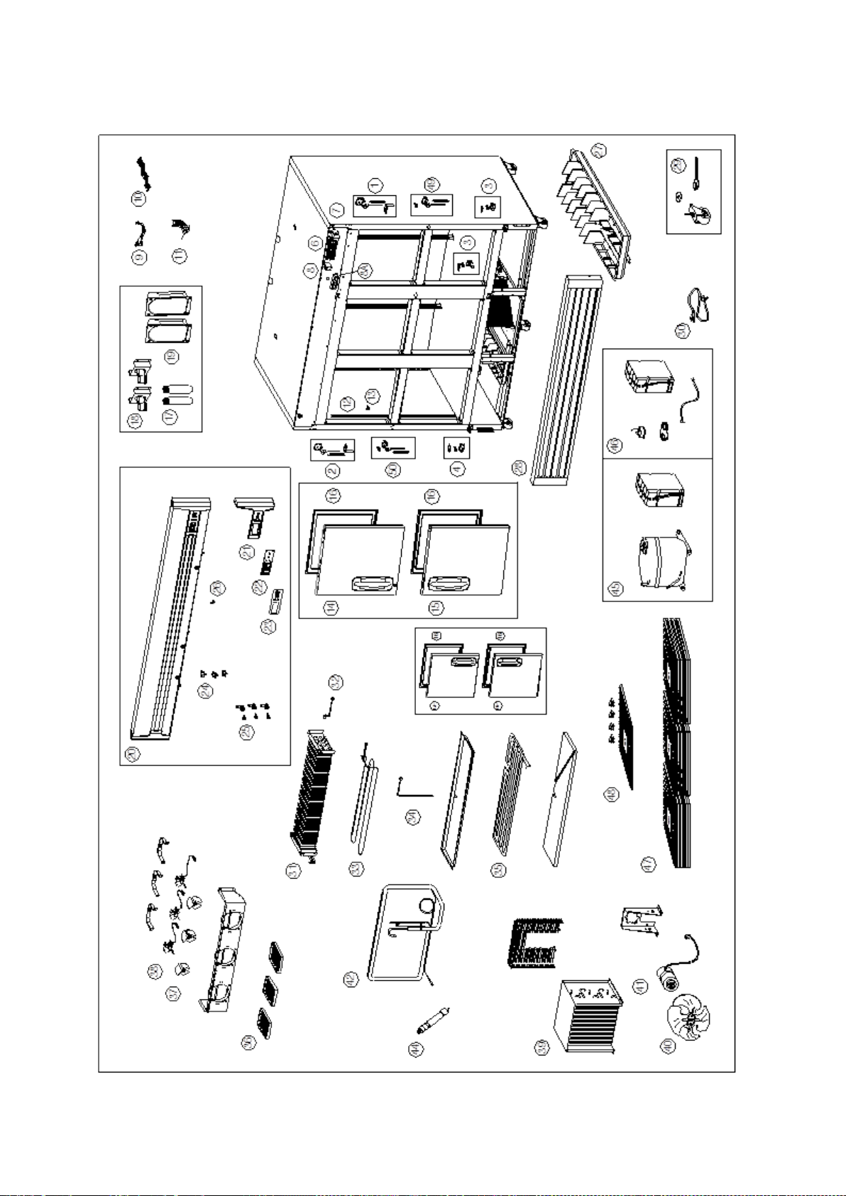
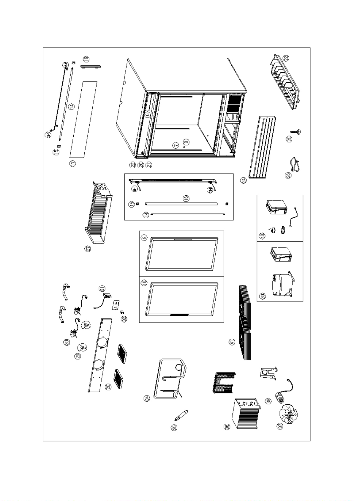
1-1. SERVICE LIST (F23/F49/F72-S , R23/R49/R72-S)
No. PART NAME
F23-S
F49-S F72-S R23-S R49-S R72-S
PART No.
1
Door Hinge Kit - Top Right 146441 146441 146441 146441 146441 146441
2 Door Hinge Kit - Top Left NA 146442 146442 NA 146442 146442
3 Door Hinge Kit - Lower Right 146412 146412 146412 146412 146412 146412
4
5
Door Hinge Kit - Lo wer Lef t NA 146413 146413 NA 146413 146413
Door Hinge Kit - Lower Center NA NA 146414 NA NA 146414
146416 146417 146418 150313 150313 150313
6
150539 150540 150541 150538 150538 150538
7 Main Transformer (115V) 146420 146420 146420 146420 146420 146420
8
9
10
11
11-1
DC Relay 146421 146421
Relay Wire Harness 146423 146423 146423 146423 146423 146423
Front PCB Wire Harness 146424 146424 146424 146424 146424 146424
146426 146428 146430 146426 146428 146430
146422
146421 146421 146421
146425 146427 146429
12
Pilaster 146411 146411 146411 146411 146411 146411
13 Shelf Clip 146489 146489 146489 146489 146489 146489
14 Door Assembly - Right Hand 146436 146437 146439 146436 146437 146439
15
16
Door Assembly - Left Hand NA 146438 146440 NA 146438 146440
Door Gasket 146444 146444 146445 146444 146444 146445
17 Lamp (115V) 146408 146408 146408 146408 146408 146408
18 Lamp Socket 146409 146409 146409 146409 146409 146409
19
20
Top Grille Assembly (115V) 146433 146434 146435 146433 146434 146435
Lamp Cover 146410 146410 146410 146410 146410 146410
21 Top Grill Cover - Right 146431 146431 146431 146431 146431 146431
146419 146419 146419 146419 146419 146419
22
150537 150537 150537 150537 150537 150537
23
Control Decal 146432 146432 146432 146432 146432 146432
- 56 – 05/15 Rev. G 146526
Page 57
No. PART NAME
146518
146518
F23-S
PART No.
F49-S F72-S R23-S R49-S R72-S
24
Light Switch 146449 146449 146449 146449 146449 146449
25 Door Lock& Key 146443 146443 146443 146443 146443 146443
26 Power Switch 146450 146450 146450 146450 146450 146450
27
28
Condensate Pan w/paper 146386 146387 146387 146386 146387 146387
Lower Grille Assembly 146388 146389 146390 146388 146389 146390
29 Caster Kit 100436 100436 100437 100436 100436 100437
30 Power Cor d 138533 138533 138657 138533 138533 138533
31
32
Evaporator Coil 146392 146394 146396 146391 146393 146395
Defrost Limit Switch 146404 146404 146404 NA NA NA
33 Defrost Heater (115V) 146397 146398 146399 NA NA NA
34 Drain Heater (115V) 146403 146403 146403 NA NA NA
35
36
Drain Pan Heater (115V) 146400 146401 146402 NA NA NA
Evaporator Fan Guard 146405 146405 146405 146405 146405 146405
37 Evaporator Fan Blade 146406 146406 146406 146406 146406 146406
38 Evaporator Fan Motor (115V) 146407 146407 146407 146407 146407 146407
39
40
Condenser Coil 146373 146375 146375 146372 146374 146375
Condenser Fan Blade 146371 146371 146371 146371 146371 146371
41 Condenser Fan Motor (115V) 146370 146370 146370 146370 146370 146370
42 Suction pipe(B) Assembly 150558 146379 146381 146376 146378 146380
43
44
Capillary Tube 146383 NA NA 146382 NA NA
Dryer 146384 146384 146385 146384 146384 146385
45 Compressor (115V) 150556 146507 146509 150311 150311 146508
46 Compressor Electrical Kit 150557 146512 146514 150312 150312 146513
146446
47 Shelf 146446 146447
48 Shelf Kit(1Shelf + 4 Clips) 146516 146517
146448 146448
146516
146446 146447
146516 146517
* Shelf: F(R) 72 - 146446 (ENDS), 146448 (CENTER)
146446
146516
* Shelf Kit: F(R) 72 - 146516 (ENDS), 146518 (CENTER)
- 57 – 05/15 Rev. G 146526
Page 58

1-2. F23-S EXPLODED VIEW
- 58 – 05/15 Rev. G 146526
Page 59

1-3. F49-S EXPLODED VIEW
- 59 – 05/15 Rev. G 146526
Page 60

1-4. F72-S EXPLODED VIEW
- 60 – 05/15 Rev. G 146526
Page 61

1-5. R23-S EXPLODED VIEW
- 61 – 05/15 Rev. G 146526
Page 62

1-6. R49-S EXPLODED VIEW
- 62 – 05/15 Rev. G 146526
Page 63

1-7. R72-S EXPLODED VIEW
- 63 – 05/15 Rev. G 146526
Page 64
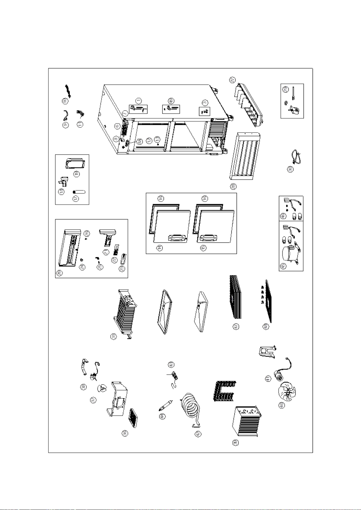
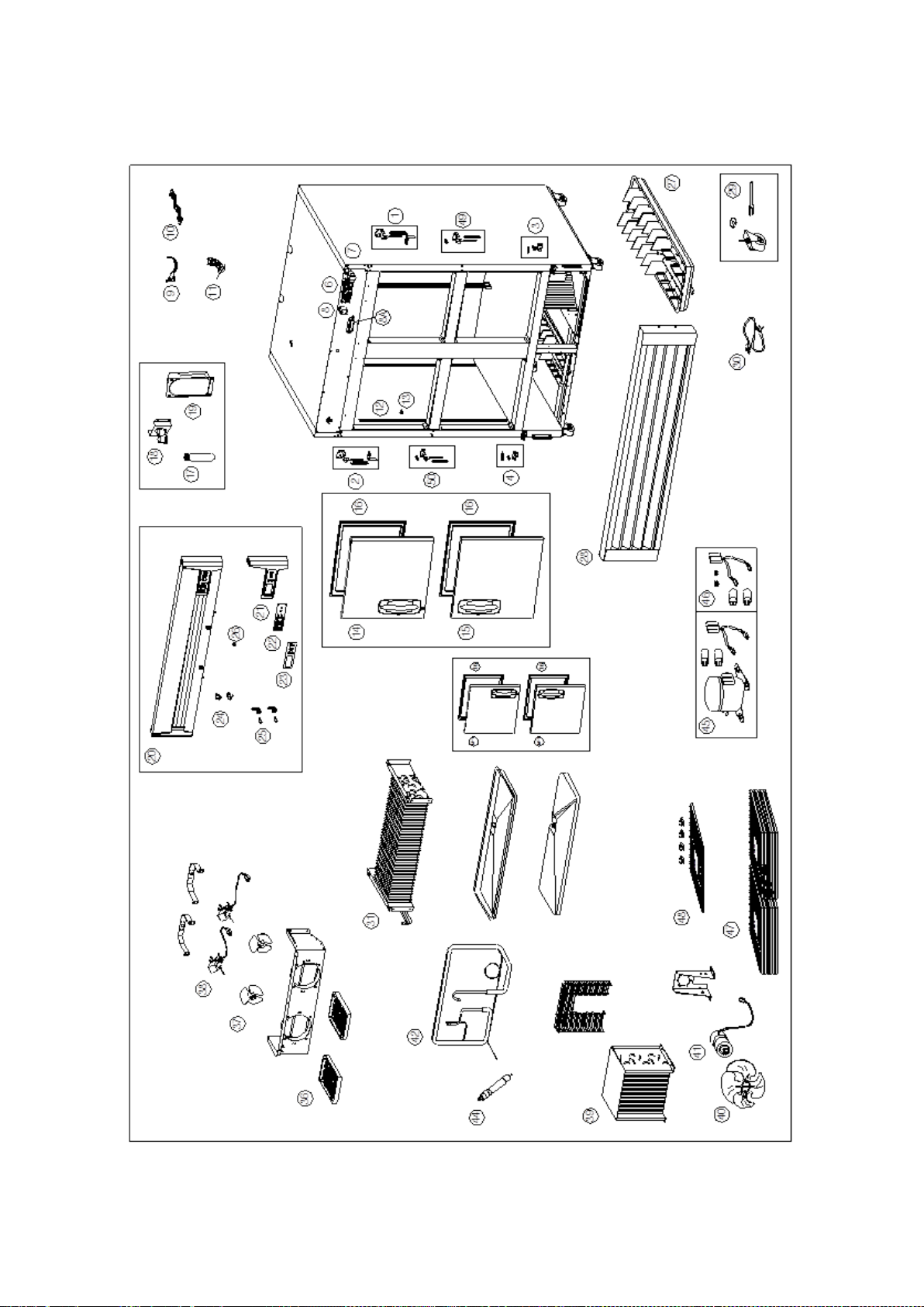
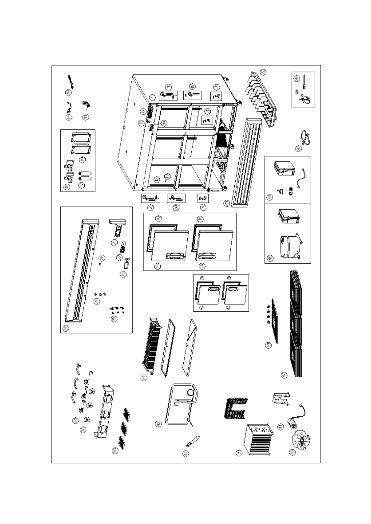
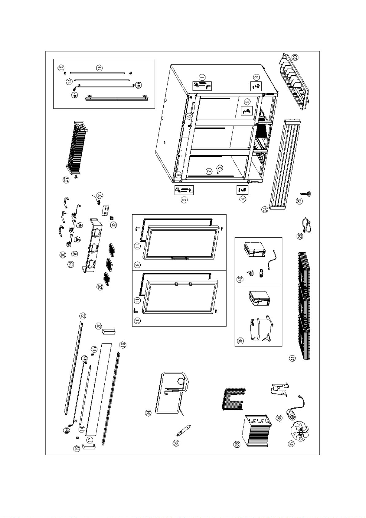
2-1. SERVICE LIST( F23/F49/F72-SH , R23/R49/R72-SH)
Control PCB Assembly (115V)
Used thru 12/2014
Control PCB Assembly (115V)
Universal (℉/℃) PCB
Temperature Sensor
use up to 12/2011
Sensor Kit (Includes
T-sensor and D-sensor)
Door Assembly - Upper Right
Hand
Door Assembly - Upper Left
Hand
Door Assembly – Lower Right
Hand
Door Assembly – Lower Left
Hand
Front PCB Assembly
Usedthru 12/2014
Front PCB Assembly
Universal (℉/℃) PCB
No. PART NAME
F23-SH F49-SH F72-SH R23-SH R49-SH R72-SH
PART No.
1
2
Door Hinge Kit - Top Right 146441 146441 146441 146441 146441 146441
Door Hinge Kit - Top Left NA 146442 146442 NA 146442 146442
3 Door Hinge Kit - Lower Right 146412 146412 146412 146412 146412 146412
4 Door Hinge Kit - Lower Left NA 146413 146413 NA 146413 146413
5
Door Hinge Kit - Lower Center NA NA 146414 NA NA 146414
146416 146417 146418 150313 150313 150313
6
150539 150540 150541 150538 150538 150538
7 Main Transformer (115V) 146420 146420 146420 146420 146420 146420
8 DC Relay 146421 146421
9
10
11
11-1
Relay Wire Harness 146423 146423 146423 146423 146423 146423
Front PCB Wire Harness 146424 146424 146424 146424 146424 146424
NA NA NA 146425 146427 146429
146426 146428 146430 146426 146428 146430
146422
146421 146421 146421
12
13
14
14-1
15
15-1
16
17
18
Pilaster 146411 146411 146411 146411 146411 146411
Shelf Clip 146489 146489 146489 146489 146489 146489
160501 160505 160510 160501 160505 160510
NA 160507 160512 NA 160507 160512
160502 160502 160511 160502 160502 160511
NA 160508 160513 NA 160508 160513
Door Gasket 160503 160503 160514 160503 160503 160514
Lamp (115V) 146408 146408 146408 146408 146408 146408
Lamp Socket 146409 146409 146409 146409 146409 146409
19 Lamp Cover 146410 146410 146410 146410 146410 146410
20
21
Top Grille Assembly (115V) 146433 146434 146435 146433 146434 146435
Top Grill Cover - Right 146431 146431 146431 146431 146431 146431
146419 146419 146419 146419 146419 146419
22
150537 150537 150537 150537 150537 150537
23 Control Decal 146432 146432 146432 146432 146432 146432
- 64 – 05/15 Rev. G 146526
Page 65
No. PART NAME
146448
146448
F23-S
PART No.
F49-S F72-S R23-S R49-S R72-S
24
Light Switch 146449 146449 146449 146449 146449 146449
25 Door Lock& Key 146443 146443 146443 146443 146443 146443
26 Power Switch 146450 146450 146450 146450 146450 146450
27
28
Condensate Pan w/paper 146386 146387 146387 146386 146387 146387
Lower Grille Assembly 146388 146389 146390 146388 146389 146390
29 Caster Kit 100436 100436 100437 100436 100436 100437
30 Power Cor d 138533 138533 138657 138533 138533 138533
31
32
Evaporator Coil 146392 146394 146396 146391 146393 146395
Defrost Limit Switch 146404 146404 146404 NA NA NA
33 Defrost Heater (115V) 146397 146398 146399 NA NA NA
34 Drain Heater (115V) 146403 146403 146403 NA NA NA
35
36
Drain Pan Heater (115V) 146400 146401 146402 NA NA NA
Evaporator Fan Guard 146405 146405 146405 146405 146405 146405
37 Evaporator Fan Blade 146406 146406 146406 146406 146406 146406
38 Evaporator Fan Motor (115V) 146407 146407 146407 146407 146407 146407
39
40
Condenser Coil 146373 146375 146375 146372 146374 146375
Condenser Fan Blade 146371 146371 146371 146371 146371 146371
41 Condenser Fan Motor (115V) 146370 146370 146370 146370 146370 146370
42 Suction pipe(B) Assembly 150558 146379 146381 146376 146378 146380
43
44
Capillary Tube 146383 NA NA 146382 NA NA
Dryer 146384 146384 146385 146384 146384 146385
45 Compressor (115V) 150556 146507 146509 150311 150311 146508
46 Compressor Electrical Kit 150557 146512 146514 150312 150312 146513
47
48
49
50
Shelf 146446 146447
Shelf Kit(1Shelf + 4 Clips) 146516 146517
Door Hinge Kit - Center Right 160504 160504 160504 160504 160504 160504
Door Hinge Kit - Center Left NA 160509 160509 NA 160509 160509
146446
146516
146518
146446 146447
146516 146517
146446
146516
146518
* Shelf: F(R) 72 - 146446 (ENDS), 146448 (CENTER)
* Shelf Kit: F(R) 72 - 146516 (ENDS), 146518 (CENTER)
- 65 – 05/15 Rev. G 146526
Page 66
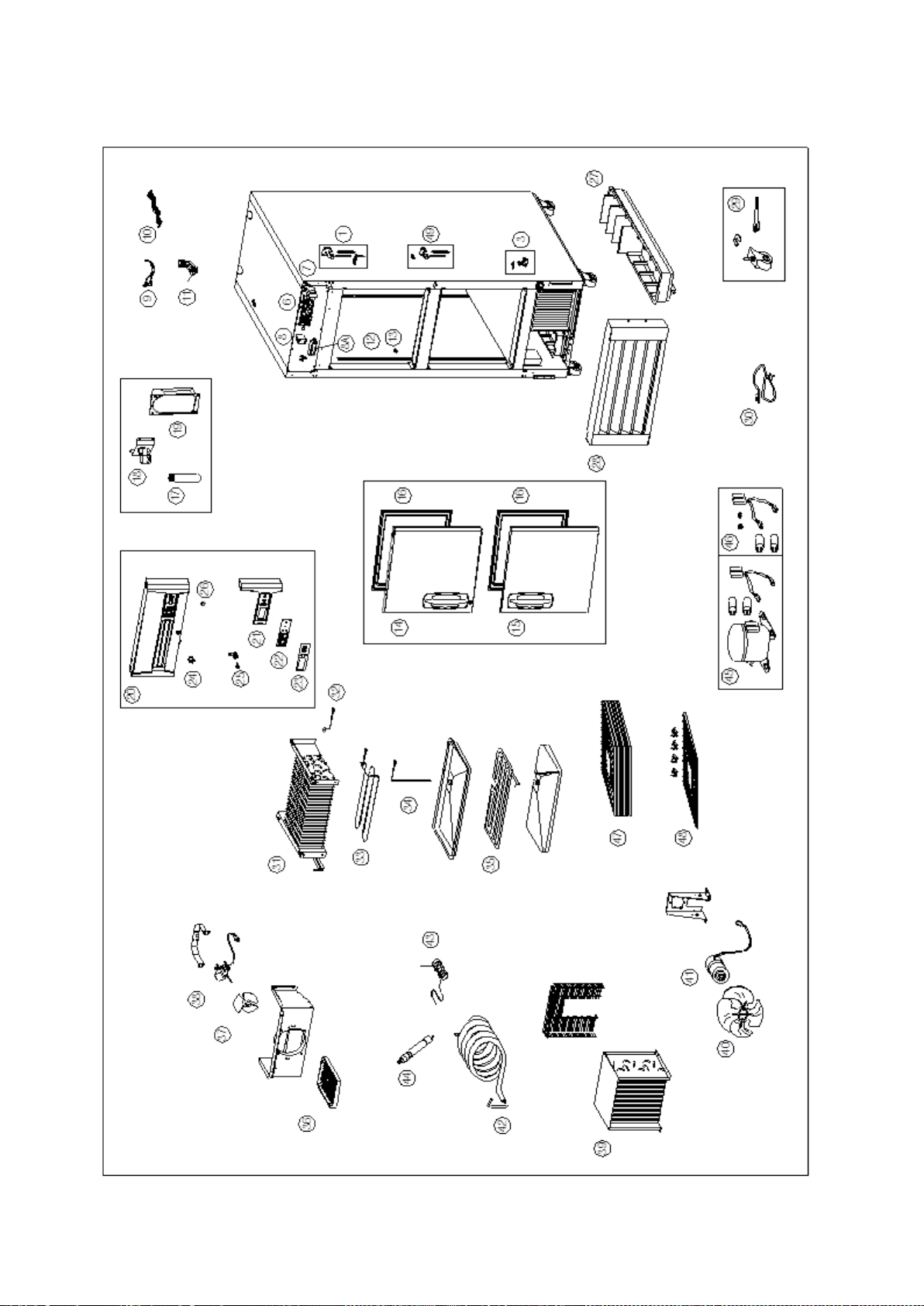
2-2. F23-SH EXPLODED VIEW
- 66 – 05/15 Rev. G 146526
Page 67
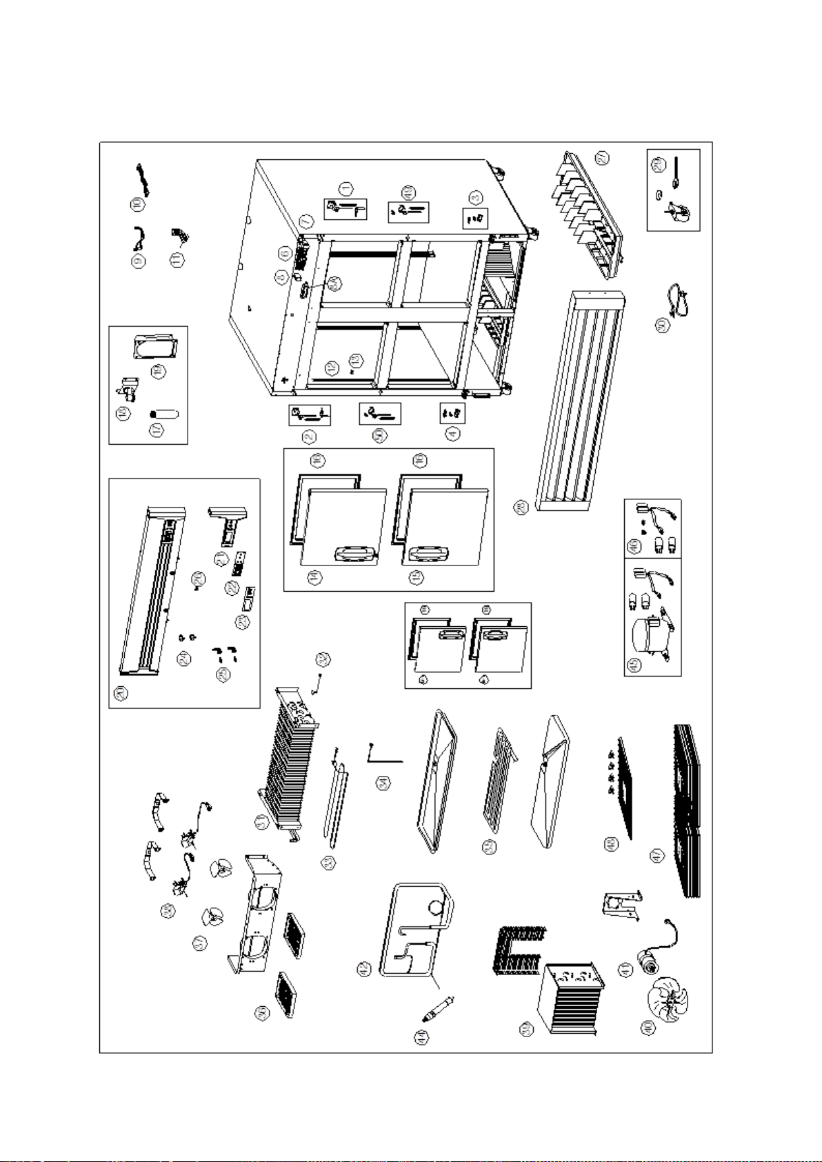
2-3. F49-SH EXPLODED VIEW
- 67 – 05/15 Rev. G 146526
Page 68
2-4. F72-SH EXPLODED VIEW
- 68 – 05/15 Rev. G 146526
Page 69
2-5. R23-SH EXPLODED VIEW
- 69 – 05/15 Rev. G 146526
Page 70
2-6. R49-SH EXPLODED VIEW
- 70 – 05/15 Rev. G 146526
Page 71
2-7. R72-SH EXPLODED VIEW
- 71 – 05/15 Rev. G 146526
Page 72
Control PCB Assembly (115V)
Used thru 12/2014
Control PCB Assembly (115V)
Universal (℉/℃) PCB
Temperature Sensor
use up to 12/2011
Sensor Kit (Includes
T-sensor and D-sensor)
Front PCB Assembly
Used thru 12/2014
Front PCB Assembly
Universal (℉/℃) PCB
3-1. SERVICE LIST (R23/R49/R72-G)
No. PART NAME
PART No.
R23-G R49-G R72-G
1
Door Hinge Kit - Top Right 160515 160515 160515
2 Door Hinge Kit - Top Left NA 160516 160516
3 Door Hinge Kit - Lower Right 160517 160517 160517
4
5
Door Hinge Kit - Lo wer Lef t NA 160518 160518
Door Hinge Kit - Lower Center NA NA 160519
150313 150313 150313
6
150538 150538 150538
7 Main Transformer (115V) 146420 146420 146420
8
8A
DC Relay 146421 146421 146421
LED DRIVER 160530 160530 150571
9 Relay Wire Harness 146423 146423 146423
10 Front PCB Wire Harness 146424 146424 146424
10A
11
LED Wire Harness 160529 160533 160535
146425 146427 146429
11-1
12
13
14
Pilaster 146411 146411 146411
Shelf Clip 146489 146489 146489
Door Assembly - Right Hand 160520 160521 160522
146426 146428 146430
15 Door Assembly - Left Hand NA 160523 160524
16
17
18
Door Gasket 160525 160525 146482
LED (6W) 160526 160526 160526
LED Fixture 160527 160527 160527
19 LED wire cover 160528 160528 160528
20
21
Top Grille Assembly 160531 160534 160536
Top Grill Cover - Right 146431 146431 146431
146419 146419 146419
22
150537 150537 150537
23 Control Decal 146432 146432 146432
- 72 – 05/15 Rev. G 146526
Page 73
No. PART NAME
PART No.
R23-G R49-G R72-G
24
Light S/W Door Switch
146449 146449 146449
24A Light Switch 160532 160532 160532
25
26
Door Lock& Key 146443 146443 146443
Power S w it ch 146450 146450 146450
27 Condensate Pan w/paper 146386 146387 146387
28 Lower Grille Assembly 146388 146389 146390
29
30
Caster Kit 100436 100436 100437
Power Cord 138533 138533 138533
31 Evaporator Coil 146391 146393 146395
32 Defrost Limit Switch NA NA NA
33
34
Defrost Heater (115V) NA NA NA
Drain Heater (115V) NA NA NA
35 Drain Pan Heater (115V) NA NA NA
36 Evaporator Fan Guard 146405 146405 146405
37
38
Evaporator Fan Blade 146406 146406 146406
Evaporator Fan Motor (115V) 146407 146407 146407
39 Condenser Coil 146372 146374 146375
40 Condenser Fan Blade 146371 146371 146371
41
42
Condenser Fan Motor (115V) 146370 146370 146370
Suction pipe(B) Assembly 146376 146379 146381
43 Capillary Tube 146382 NA NA
44 Dryer 146384 146384 146385
45
46
Compressor (115V) 150311 150556 150556
Compressor Electrical Kit 150312 150557 150557
47 Shelf 146446 146447 146446 / 146448
48 Shelf Kit(1Shelf + 4 Clips) 146516 146517 146516 / 146518
* Shelf: F(R) 72 - 146446 (ENDS), 146448 (CENTER)
* Shelf Kit: F(R) 72 - 146516 (ENDS), 146518 (CENTER)
- 73 – 05/15 Rev. G 146526
Page 74

3-2. R23-G EXPLODED VIEW
- 74 – 05/15 Rev. G 146526
Page 75

3-3. R49-G EXPLODED VIEW
- 75 – 05/15 Rev. G 146526
Page 76

3-4. R72-G EXPLODED VIEW
- 76 – 05/15 Rev. G 146526
Page 77

2. MERCHANDISERS
1-1. SERVICE LIST (GR26H, GR48S, GR70H)
PART No.
No. PART NAME
GR26H GR48S GR70H
1 Door Hinge Kit - Top Right 146481 NA 160515
2 Door Hinge Kit - Top Left NA NA 160516
3 Door Hinge Kit - Lower Right 146471 NA 160517
4 Door Hinge Kit - Lower Left NA NA 160518
5 Door Hinge Kit - Lower Center NA NA 160519
6 Ballast 146491 146491 146491
7 Pilaster 146470 146470 146470 / 146411
8 Shelf Clip 146489 146489 146489
9 Door Assembly - Right Hand 146478 146477 146476
10 Door Assembly - Left Hand NA 146480 146479
11 Door Gasket 146483 NA 146482
12-1
12-2
13-1
13-2
14 Lamp (115V) 146466 / 146467 146466 146466
15 Lamp Cover End 146468 146468 146468
16 Lamp Cover 146469 146469 146469
17 Advertising Panel - Blank 146495 146494 146493
18 Advertising Panel Frame 146497 NA NA
19 Advertising Panel Frame-Left NA 146505 146500
20 Advertising Panel Frame-Right NA 146506 146501
Advertising Panel Wire A 150190 150524 150546
Advertising Panel Wire B NA 150525 150547
Interior Light Wire A NA 150526 150548
Interior Light Wire B NA 150527 150549
21 Advertising Panel Frame-Bottom NA 146503 146498
22 Advertising Panel Frame-Top NA 146504 146499
23 Condensate Pan w/paper 146386 146460 146459
24 Lower Grille Assembly 146463 146462 146461
25 Foot Kit 146502 146502 146502
- 77 – 05/15 Rev. G 146526
Page 78

PART No.
No. PART NAME
GR26H GR48S GR70H
26 Power Cord 146475 146475 138533
27 Evaporator Coil 146465 146464 146395
28 Evaporator Fan Guard 146405 146405 146405
29 Evaporator Fan Blade 146406 146406 146406
30 Evaporator Fan Motor 146407 146407 146407
31 Temperature Control 146474 146473 146472
32 Light Switch 146450 146450 146450
33 Capillary Tube 146458 NA NA
34 Suction pipe(B) Assembly 146457 146456 146380
35 Dryer 146384 146384 146385
36 Condenser Coil 146372 146455 146375
37 Condenser Fan Blade 146371 146371 146371
38 Condenser Fan Moto 146370 146370 146370
39 Compressor 146452 146451 146451
40 Compressor Electrical Kit 146454 146453 146453
41 Shelf 146488 146486 / 146487 150507 / 150508
42 Shelf Kit(1Shelf + 4Clips) 146523 146521 / 146522 150509 / 150510
* Shelf: GR48S - 146486 (LE FT), 146487 (RIGHT)
GR70H - 150507 (ENDS), 150508 (CENTER)
* Shelf Kit: GR48S - 146521 (LEFT), 146522 (RIGHT)
GR70H - 150509 (ENDS), 140510 (CENTER)
- 78 – 05/15 Rev. G 146526
Page 79

1-2. GR26H EXPLODED VIEW
- 79 – 05/15 Rev. G 146526
Page 80
1-3. GR48S EXPLODED VIEW
- 80 – 05/15 Rev. G 146526
Page 81
1-4. GR70H EXPLODED VIEW
- 81 – 05/15 Rev. G 146526
Page 82

D. COMPRESSOR & ACCESSORIES CHECK LIST
1. F23-S/SH, R49/R72-G - - - - - - - - - - - - - - - - - - - - - - - - - - - - - - - - - - - - - - - - D2
2. F49-S/SH - - - - - - - - - - - - - - - - - - - - - - - - - - - - - - - - - - - - - - - - D3
3. F72-S/SH - - - - - - - - - - - - - - - - - - - - - - - - - - - - - - - - - - - - - - - - D4
4. R23/R49-S/SH, R23-G - - - - - - - - - - - - - - - - - - - - - - - - - - - - - - - - - - - - - - - - D5
5. R72-S/SH - - - - - - - - - - - - - - - - - - - - - - - - - - - - - - - - - - - - - - - - D6
6. GR26H - - - - - - - - - - - - - - - - - - - - - - - - - - - - - - - - - - - - - - - - D7
7. GR48S/GR70H - - - - - - - - - - - - - - - - - - - - - - - - - - - - - - - - - - - - - - - - D8
- 82 – 05/15 Rev. G 146526
Page 83
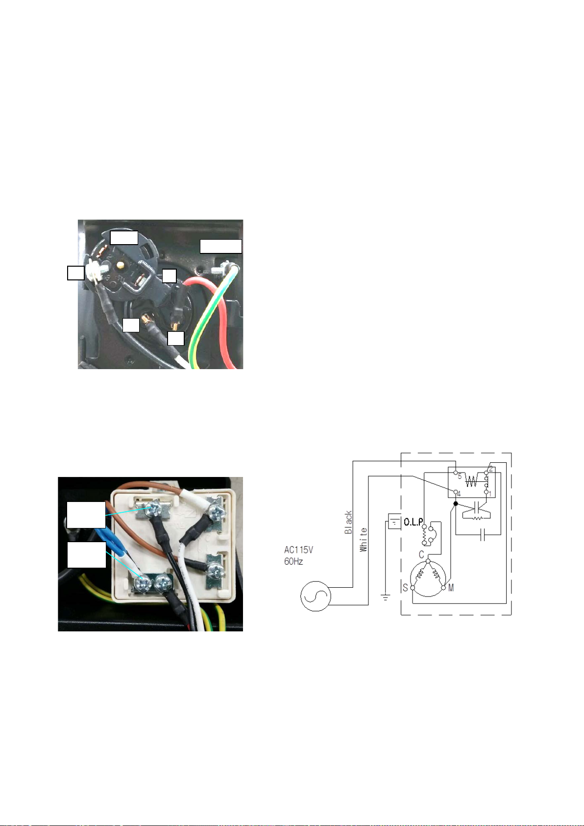
1. F23-S/SH, R49/R72-G
C
S
M 3 OLP
EARTH
① Compressor Spec. : NEK2150GK (R-404A), 115V/60Hz, CSR Type
② Maker : EMBRACO
③ Cooling Capacity : 628kcal/Hr - LBP
④ Starting Capacitor Spec. : 189~227 ㎌ / 165V
⑤ Running Capacitor Spec. : 25 ㎌ / 400V
⑥ Relay Spec. : RVA9AD3C-121
⑦ O.L.P Spec. : T0873/G9
* Comp. Winding Resistance: C - M → 0.77Ω, C - S → 4.5Ω (RT 25
* O.L.P Winding Resistance: 3- C → 0 Ω (OK), ∞
* Relay Winding Resistance: 1 -2 → 0 Ω (OK), ∞
BLACK
WIRE
WHITE
WIRE
Ω (NG)
Ω (NG)
℃(77℉))
< COMP. Wiring Diagram>
- 83 – 05/15 Rev. G 146526
Page 84
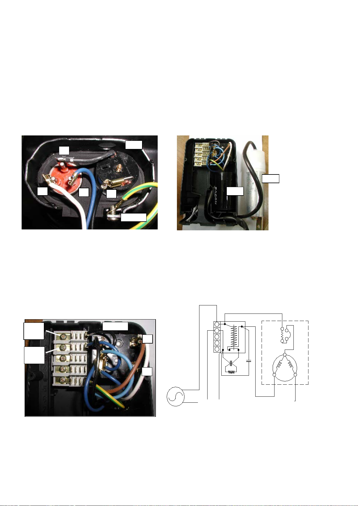
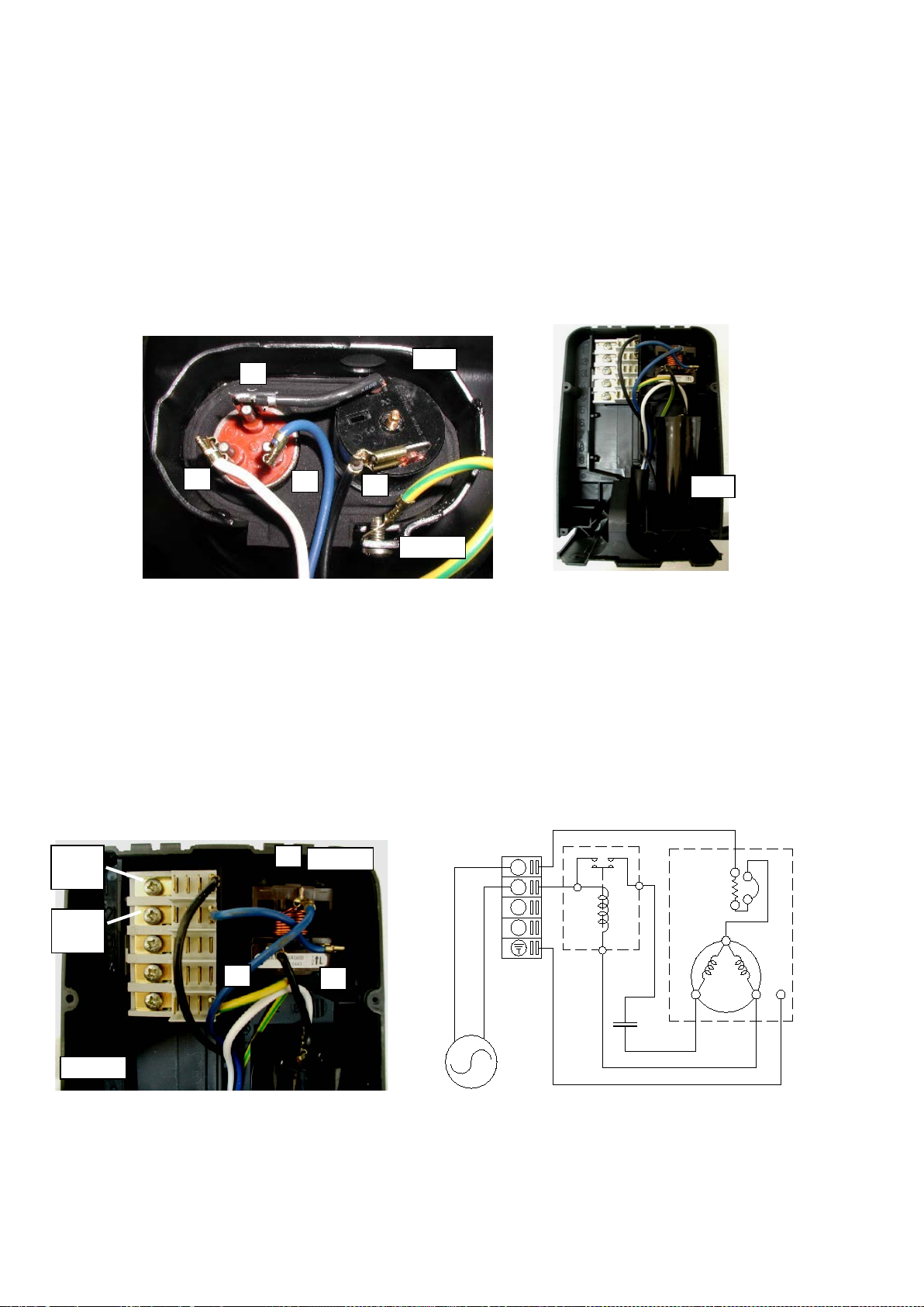
2. F49-S/SH
M
S C OLP
EARTH
3
R/C
S/C
< RELAY BOX >
2
R/C
1
Black
60Hz
AC115V
1
White
S/C
3L
5
4
2N
3
M
S
C
OLP
Black
White
2
1
RELAY
① Compressor Spec. : CAJ2432Z (A) (R-404A), 115V/60Hz, CSR Type
② Maker : TECUMSEH-FRANCE
③ Cooling Capacity : 807kcal/Hr - LBP
④ Starting Capacitor Spec. : 315 ㎌ / 160V
⑤ Running Capacitor Spec. : 30 ㎌ / 400V
⑥ Relay Spec. : 3ARR3*5R*
⑦ O.L.P Spec. : GA3PJU00
* Comp. Winding Resistance: C - M → 0.56Ω, C - S → 3.67Ω (RT 20
* O.L.P Winding Resistance: 3 - C → 0 Ω (OK), ∞
* Relay Winding Resistance: 1 - 2 → 0 Ω (OK), ∞
Ω (NG)
Ω (NG)
℃(68℉))
wire
wire
< COMP. Wiring Diagram>
- 84 – 05/15 Rev. G 146526
Page 85
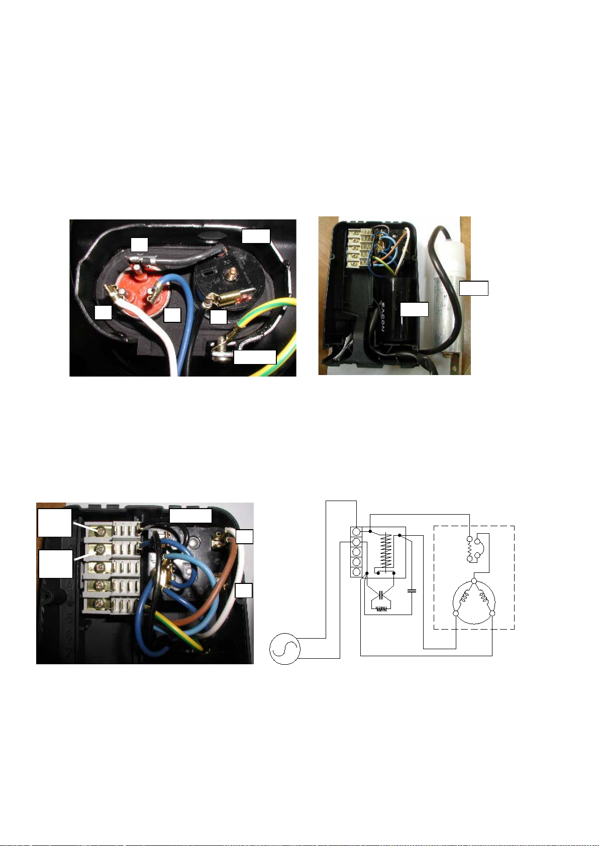
3. F72-S/SH
M S C
OLP
EARTH
3
R/C
S/C
< RELAY BOX >
Red
60Hz
Red
1
AC220V
3L
5
4
2N
M
S
C
3
2
1
R/C
S/C
OLP
Black
White
2
1
RELAY
① Compressor Spec. : CAJ2446Z (H) (R404a), 220V/60Hz, CSR Type
② Maker : TECUMSEH-FRANCE
③ Cooling Capacity : 1,219kcal/Hr - LBP
④ Starting Capacitor Spec. : 88 ㎌ / 260V
⑤ Running Capacitor Spec. : 15 ㎌ / 400V
⑥ Relay Spec. : 3ARR3*3A*
⑦ O.L.P Spec. : MST00AHN
* Comp. Winding Resistance: C - M → 1.16Ω, C - S → 8.14Ω (RT 20
* O.L.P Winding Resistance: 3 - C → 0 Ω (OK), ∞
* Relay Winding Resistance: 1 - 2 → 0 Ω (OK), ∞
Ω (NG)
Ω (NG)
wire
wire
℃(68℉))
< COMP. Wiring Diagram>
- 85 – 05/15 Rev. G 146526
Page 86
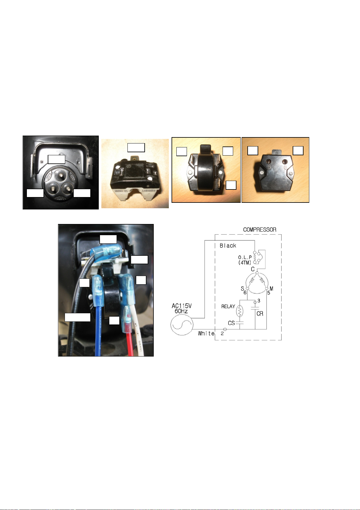
4. R23/R49-S/SH, R23-G
< COMP. Terminal >
C(1)
S(6)
M(5)
3
2 1 5
6
< RELAY >
< OLP >
4TM
OLP
RELAY
3 2 1
4TM
① Compressor Spec. : SK1A1C-L2W (R-134a), 115V/60Hz, CSR Type
② Maker : SAMSUNG -KOREA
③ Cooling Capacity : 303kcal/Hr - LBP
④ Starting Capacitor Spec. : 125 ㎌ / 125V
⑤ Running Capacitor Spec. : 12 ㎌ / 250V
⑥ Relay Spec. : J531Q34E220M350-3(220MB3)
⑦ O.L.P Spec. : 4TM795TFBZZ-53
< COMP. Wiring Diagram>
* Comp. Winding Resistance: C - M → 1.12Ω, C - S → 5.95Ω
* O.L.P Winding Resistance: 1 - 1-1 → 0 Ω (OK), ∞
Ω (NG)
* Relay Winding Resistance: M (5) - 4 → 0 Ω (OK), ∞
* PTC: 22Ω
On/Off Temperature - O/T: 140±5 ℃, C/T: 61±11℃
ST: 23A, UT: 7.48A
Ω (NG)
S (6) - 4 → ∞ Ω (OK)
- 86 – 05/15 Rev. G 146526
Page 87
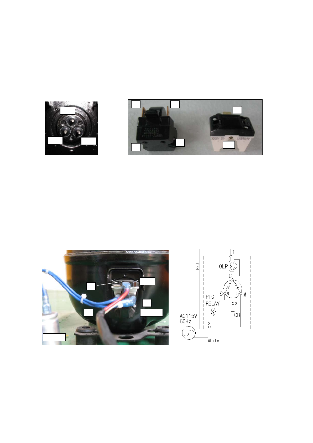
5. R72-S/SH
M S C
OLP
EARTH
1
< RELAY BOX >
S/C
S/C
Earth
2
4
3
L
1
S
60Hz
AC115V
OLP
C
S
M
3
Black
White
Black
White
3 L RELAY
S
Fig.1
① Compressor Spec. : CAJ4461Y (A) (R-134a), 115V/60Hz, CSIR Type
② Maker : TECUMSEH-FRANCE
③ Cooling Capacity : 1,586kcal/Hr - HBP
④ Starting Capacitor Spec . : 250 ㎌ / 160V
⑤ Relay Spec. : 3ARR18A100B
⑥ O.L.P Spec. : GA3SJU81 or CRA38016
* Comp. Winding Resistance: C - M → 0.7Ω, C - S → 4.5Ω (RT 20
* O.L.P Winding Resistance: 1 - C → 0 Ω (OK), ∞
* Relay Winding Resistance: L - 3 → 0 Ω (OK), ∞
Ω (NG)
Ω (NG)
℃(68℉))
L - S → ∞ Ω (OK)
* Measuring the resistance, the bottom of the relay must be downward (like fig1)
wire
wire
< COMP. Wiring Diagram>
- 87 – 05/15 Rev. G 146526
Page 88
6. GR26H
< Comp. Terminal >
M(5)
S(6)
C(1)
< OLP >
< RELAY
1
1-1 2 3 5 6 1 OLP
RELAY
Fig.1
3
2
① Compressor Spec. : SK182C-L2U (R-134a), 115V/60Hz, RSCR Type
② Maker : SAMSUNG-KOREA
③ Cooling Capacity : 243kcal/Hr - LBP
④ Relay Spec. : PTHAR-T4R7M180D/J531Q32E4R7M1802
⑤ O.L.P Spec. : 4TM444 NHBYY-53
* Comp. Winding Resistance: C - M → 2.3Ω, C - S → 3.8Ω (RT 25
* O.L.P Winding Resistance: 1 - 1-1 → 0 Ω (OK), ∞
* Relay Winding Resistance: 5 - 6 → 0 Ω (OK), ∞
Ω (NG)
Ω (NG)
℃(77℉))
2 - 3 → 0 Ω (OK), ∞ Ω (NG)
* Measuring the resistance, the bottom of the relay must be downward (like fig.1)
< COMP. Wiring Diagram>
- 88 – 05/15 Rev. G 146526
Page 89
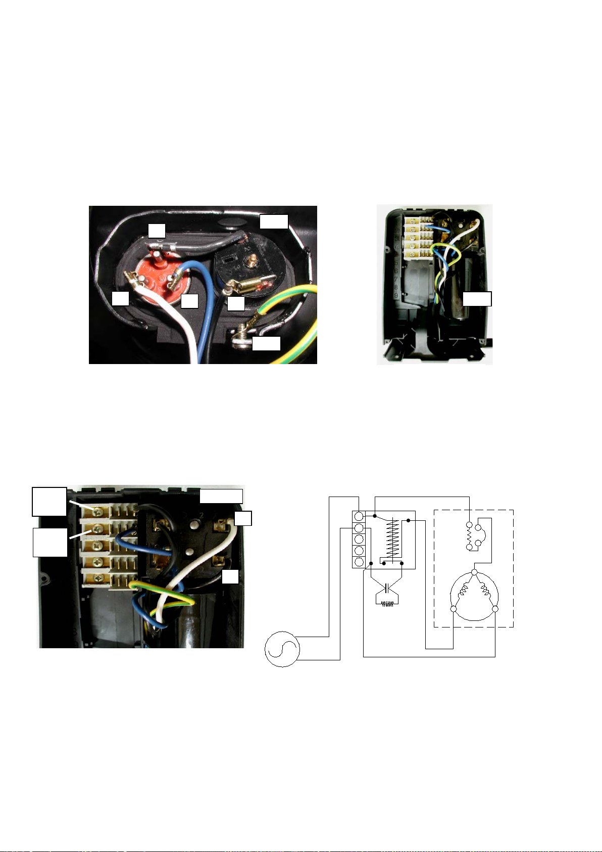
7. GR48S/GR70H
M S C
OLP
Earth
3
< RELAY BOX >
S/C
Black
White
2
1
RELAY
White
60Hz
2N
4
5
3L
AC115V
Black
1
S
M
OLP
C
3
S/C
1
2
① Compressor Spec. : CAJ4476Y (A) (R-134a), 115V/60Hz, CSIR Type
② Maker : TECUMSEH-FRANCE
③ Cooling Capacity : 1,946kcal/Hr - HBP
④ Starting Capacitor Spec. : 250 ㎌ / 160V
⑤ Relay Spec. : 3ARR3*2M*
⑥ O.L.P Spec. : CRA38014
* Comp. Winding Resistance: C - M → 0.72Ω, C - S → 3.68Ω (RT 20
* O.L.P Winding Resistance: 3 - C → 0 Ω (OK), ∞
* Relay Winding Resistance: 1 - 2 → 0 Ω (OK), ∞
Ω (NG)
Ω (NG)
wire
wire
℃(68℉))
< COMP. Wiring Diagram>
- 89 – 05/15 Rev. G 146526
 Loading...