

Page 1

OWNER’S MANUAL
JVM410H HEAD &
JVM410C COMBO
Page 2

WARNING! IMPORTANT SAFETY INSTRUCTIONS
ENGLISH
WARNING:
Before going any further, make sure that
your amplier is compable with your
mains electricity supply. If you have any
doubt, please seek help from a qualied
technician – your Marshall dealer can help
you in this respect.
MAINS INPUT & FUSE:
The specic mains input voltage rang
that your amplier has been manufactured
for is indicated on the rear panel of the
amplier. Your amplier is provided with
a detachable mains (power) lead, which
should be connected to the MAINS INPUT
socket on the rear panel of the amplier
(Rear Panel Function #13). The correct
value and type of mains fuse is specied
on the rear panel of the amplier. NEVER
aempt to bypass the fuse or t one of the
incorrect value or type.
TRANSPORTING YOUR EQUIPMENT:
Please ensure that your amplier is
switched o, unplugged from the mains
electricity supply and all removable
cables have been disconnected from your
equipment before aempng to move it.
IMPORTANT SET UP INFORMATION:
1. When using JVM410H head, or
JVM410C combo with an extension speaker
cabinet(s), make sure that the speaker
cabinet(s) is connected to the correct
impedance loudspeaker jack socket(s) on
the rear panel of the amplier. See the
LOUDSPEAKERS guide in this manual for
specic informaon regarding impedance
matching (Rear Panel Function #19).
WARNING Failure to do the above may
damage your amplier. When connecng
a speaker cabinet make sure that you
use a proper speaker cable. Never use a
screened (shielded) guitar cable for this
purpose.
2. Ensure that the POWER switch (Front
Panel Function #12) is set to the OFF
posion.
3. Connect the supplied mains (power)
lead into the MAINS INPUT (Rear Panel
Function #13) rst and then into the mains
electricity supply.
4. Ensure that the MASTER 1 and MASTER
2 controls on the front panel are set to
zero (Front Panel Function #7).
5. Plug your guitar into the INPUT jack
socket on the front panel (Front Panel
Function #1).
6. Ensure that the STANDBY switch (Front
Panel Function #11) is in the OFF posion.
7. Turn the front panel POWER switch
to the ON (I) posion and wait for a few
minutes before going to point 8.
8. Engage the amplier by switching
STANDBY to the ON posion.
9. Turn the volumes up to your preferred
level and your amplier is ready to play.
PLEASE READ THIS MANUAL CAREFULLY BEFORE PLUGGING IN.
FOLLOW ALL INSTRUCTIONS AND HEED ALL WARNINGS.
KEEP THESE INSTRUCTIONS.
Page 3

ENGLISH
This device complies with part 15 of the FCC Rules. Operaon is subject to the
following two condions:
1. This device may not cause harmful interference, and
2. This device must accept any interference received, including interference
that may cause undesired operaon.
This equipment has been tested and found to comply with the limits for a Class B
digital device, pursuant to part 15 of the FCC rules. These limits are designed to
provide reasonable protecon against harmful interference in a residenal
installaon.
This equipment generates, uses and can radiate radio frequency energy and, if not installed and used in accordance with the instrucons, may cause harmful
interference to radio communicaons.
However, there is no guarantee that interference will not occur in a parcular
installaon. If this equipment does cause harmful interference to radio or
television recepon, which can be determined by turning the equipment o and on, the
user is encouraged to try to correct the interference by one or more of the
following measures:
• Reorient or relocate the receiving antenna.
• Increase the separaon between the equipment and the receiver.
• Connect the equipment into an outlet on a circuit dierent from that to
which the receiver is connected.
• Consult the dealer or an experienced radio/TV technician for help.
CAUTION: Any changes or modicaons not expressly approved by the party
responsible for compliance may void the users authority to operate the equipment.
This device complies with CAN ICES-3(B)/NMB-3(B)
COMPLIANCE STATEMENT
JVM410H Head JVM410C Combo
Power (RMS) 100W 100W
Valves 5x ECC83 + 4x EL34 5x ECC83 + 4x EL34
Main Guitar - Input Impedance 470kΩ 470kΩ
Emulated Output - Level +4dBu +4dBu
FX Send Level - selectable -10dBV, +4dBu -10dBV, +4dBu
Weight 22kg 34.5kg
Size (mm) W, H, D 750 x 310 x 215 690 x 510 x 265
TECHNICAL SPECIFICATIONS
Page 4

ENGLISH
INTRODUCTION
From humble beginnings in 1962 Marshall became a global icon. Synonymous with
the sound of rock and blues rock music, the legendary power and disncve tone of
Marshall ampliers can be heard on many inuenal studio and live recordings from
the past half century. Marshall ampliers have stood the test of me, with some of our
classic products from the ‘60s, ‘70s, ‘80s & ‘90s sll made today at the Marshall factory
in Bletchley, England.
Marshall has over the years earned a reputaon for craing great sounding, dependable,
hard-wearing and hardworking ampliers for all guitarists, and our values haven’t
changed, this remains our primary goal. Through expert R&D and bold design we connue
to innovate, building on our heritage and reputaon as the number one Brish amp
maker.
The all-valve JVM410H and JVM410C are made in England by a skilled and dedicated
workforce whose crasmanship and aenon to detail produce some of the best loved
and most iconic guitar ampliers and speaker cabinets ever made.
The highly acclaimed JVM4 Series is at the apex of six decades of tonal and funconal
evoluon; an evoluon that has been driven not only by our desire to make the best
ampliers in the world , but by our customers—professional arst and amateur enthusiast
alike. At Marshall we fully understand the necessity of achieving the right tone, feel and
funconality to help inspire you to reach your creave potenal.
The JVM4 Series features 4 tonally independent channels, each with 3 modes, oering a
broad tonal palee from which to shape your sound. With the inclusion of an FX loop,
two master volumes and four independent channel reverbs, JVM4 is versale too.
To control JVM4’s wide tonal range and funconality requires a unique footswitching
system. The programmable 6-way Stompware® footcontroller enables you to harness
the power of JVM4, giving you serious control of your sound during performance, either
by switching panel funcons directly or programming groups of panel sengs to form
Presets stored to single footswitch buon.
We sincerely hope that your JVM4 Series amplier proves indispensable and that it
provides you with years of legendary Marshall tone, whatever your playing situaon.
Thank you for choosing Marshall.
- The Marshall Team
Page 5

ENGLISH
OVERVIEW
CHANNELS, MODES & MEMORY
Presenng the 4 channel, 100 Wa, allvalve JVM4 amplier (JVM410H head or
JVM410C 2x12” combo). Its 4 channels
feature 3 modes, giving you a total of 12
dierent modes to choose from - each
with its own unique gain structure. Even
though its front panel contains a total of 28
control knobs and 8 LED switches, JVM4 is
simple to understand and operate thanks
to its extremely logical front and rear panel
layouts.
The front panel contains dedicated sets of
controls for each of its 4 channels - CLEAN,
CRUNCH, OD1 & OD2 - plus MASTER and
REVERB secons. Each channel contains
the familiar controls, VOLUME, BASS,
MIDDLE, TREBLE and GAIN. The REVERB
secon consists of 4 level controls, one for
each channel, while the MASTER secon
is comprised of 2 footswitchable master
volumes: MASTER 1/MASTER 2, plus
master RESONANCE and PRESENCE
controls that work universally on all 4
channels.
Each of the 4 channels has 3 switchable
modes. These are selected by the
MODE switch dedicated to each
channel. To select a channel press its
respecve MODE switch or step on the
relevant buon on the supplied 6-way
Stompware® footswitch. To scroll through
the selected channel’s 3 modes keep
pressing the said switch and the colour
of the LED in the switch will change from
green to orange to red and then back to
green. Doing this steps-up the gain level
each me (red being the highest and green
the lowest for each channel) and changes
the channel’s tonal voicing.
When you leave and then reselect a
channel, it will automacally recall the last
acve mode as all 4 channels remember
the last mode they were in unl a change
is made. For instance, if you select the
CRUNCH channel’s orange mode and
then go to the CLEAN channel, when you
reselect the CRUNCH channel it will sll
be in orange mode.
In addion to channel and mode selecon,
other features that are switchable via the
front panel and the footswitch are REVERB
(on/o) MASTER 1 & MASTER 2, and
SERIES/PARALLEL FX LOOP (on/o). All 3
of these funcons are also remembered by
each mode.
To sum up, each of the JVM4’s 12 modes
will remember its most recent REVERB,
FX LOOP and MASTER volume seng.
Addionally, mode setups can also be
saved and recalled to one of 128 locaons
via MIDI.
STOMPWARE® 6-WAY FOOTSWITCH
The JVM410H and JVM410C are supplied
with a Stompware® 6-way programmable
footswitch, which can be connected to the
amp via any standard guitar cable.
Note: The supplied footswitch lead is
unscreened and not suitable for guitar.
The footswitch features 7 LEDS: CLEAN,
CRUNCH, OD1, OD2, MASTER, REVERB
and FX. The LEDs for each of the 4
channels are 3-coloured: green, orange
and red, visually telling you which channel
and mode is selected alongside the status
of MASTER, REVERB and FX LOOP.
The supplied Stompware® footswitch
enables you to assign any of its 6 buons
Page 6

ENGLISH
to instantly recall any front panel switch
funcon (Switch Store Mode) or complete
channel setup (Preset Store Mode) in any
order and combinaon.
SWITCH STORE MODE
In Switch Store mode any footswitch
buon is assigned to act as any one of the
amp’s front panel switches: CHANNEL/
MODE, REVERB on/o, MASTER 1/2 and
FX LOOP on/o.
If a footswitch buon is assigned to select
a parcular channel, once it has been
acvated that footswitch buon can be
used to scroll through the three modes,
just like its respecve front panel switch.
PRESET STORE MODE
In Preset Store mode each footswitch
buon can be programmed to instantly
call up a combinaon of front panel switch
opons to form a Preset. For example, you
could program the footswitch so that:
Buon #1 = CRUNCH channel, green
mode with MASTER volume ‘1’, REVERB
‘on’ and FX LOOP ‘o’.
Buon #2 = CLEAN channel, red mode
with MASTER volume ‘2’, REVERB ‘o’ and
FX LOOP ‘on’.
All Preset sengs are stored within the
footswitch; this means that it can be
plugged into any JVM4 amplier and your
stored footswitch sengs will be instantly
recalled.
Details on how to program your footswitch
can be found later in this manual (Front
Panel Function #10).
POWER AMP
The power-stage of the 100 Wa JVM4
is based on the one found in the JCM800
2203 and 1959 Superlead ampliers
responsible for the legendary Marshall
roar. It has been adjusted to suit the wide
variety of tones found in JVM4 channels
and modes. This power amp secon
features PRESENCE and RESONANCE
controls to help shape the overall tone of
your JVM4 amplier.
Your JVM4 is also equipped with a silent
recording mode. When the STANDBY
switch is in the OFF posion, the powerstage is disabled, but the rest of the
amplier remains fully operaonal.
REVERB
The JVM410H and JVM410C are
equipped with studio quality reverb,
routed in parallel to the main signal and
mixed by means of a valve. When reverb
is engaged no degradaon of the direct
signal occurs and when it’s ‘o’ it is
eecvely removed from the circuit. Each
of the JVM4’s channels also has its own
dedicated REVERB level control.
The REVERB switching has been designed
to avoid abrupt cut os in the reverb tail,
so when changing from channel to channel
or switching reverb ‘o’, its tail decays
naturally.
STANDBY & SILENT RECORDING
(Front Panel Function #11)
When the amplier is in STANDBY (OFF)
the whole preamp secon connues
running at its nominal voltages whilst
the power-stage remains in a ‘standby’
status. This allows the amplier to be
used for silent recording or for preamp
purposes using the EMULATED LINE OUT
(Rear Panel Function #16).
OVERVIEW (CONT.)
Page 7

ENGLISH
NOTES
Page 8
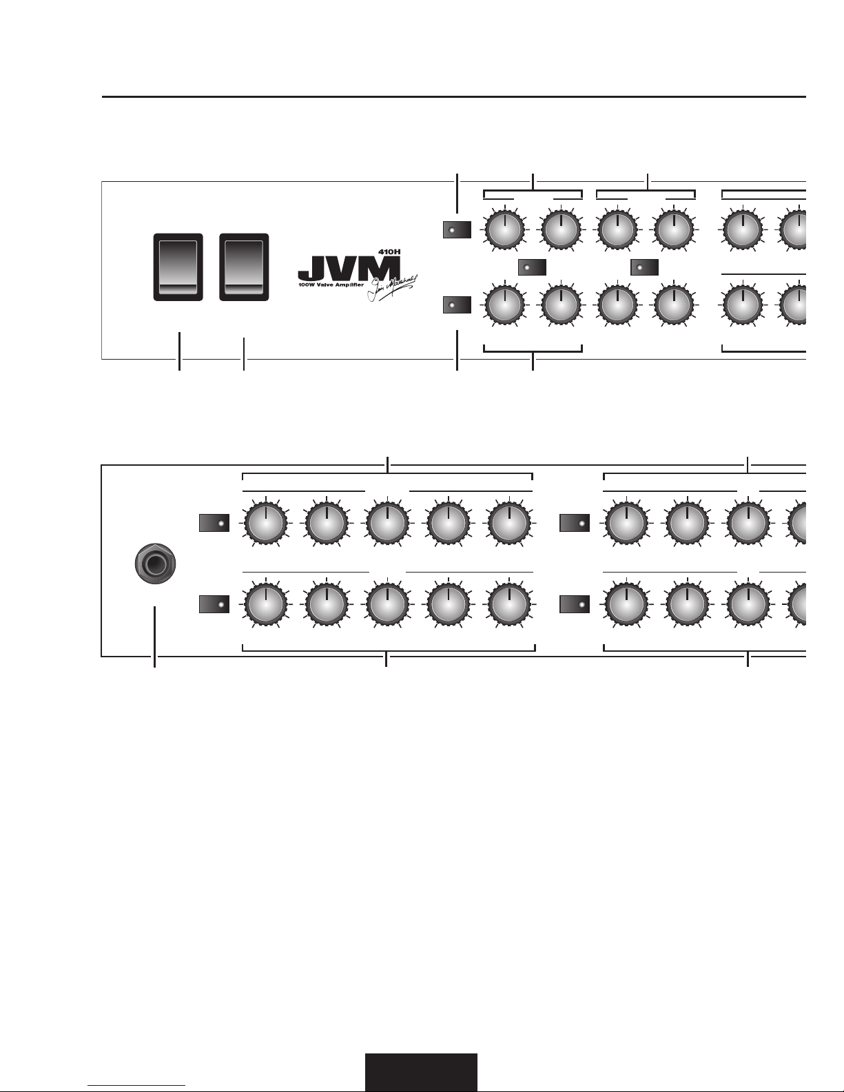
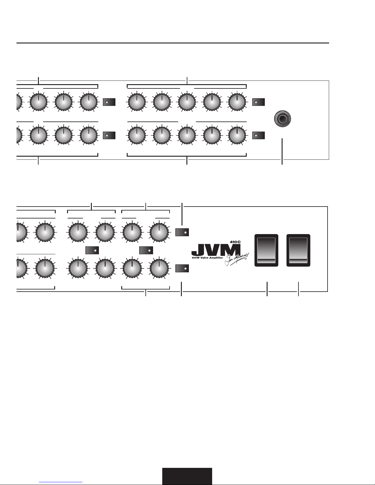
FRONT PANEL FUNCTIONS
ENGLISH
1. INPUT
Input jack socket for your guitar cable. Use
a good quality screened/shielded guitar
cable to help prevent noise interference.
2. CLEAN CHANNEL
CLEAN GREEN MODE: This is the cleanest
of the three modes and, in keeping with
tradional clean amps, it uses a simple
and straighorward circuit, keeping the
signal as pure as possible. In this mode the
channel’s VOLUME control is taken out of
circuit as is the case in vintage ampliers
of this nature. This is the only mode where
this happens.
CLEAN ORANGE MODE: By adding another
gain stage aer the tone stack we get a
punchier sound that’s easy to overdrive.
As in the rest of the modes the channel’s
VOLUME control is now acve.
CLEAN RED MODE: This mode pushes the
original clean sound even more and transforms into a pseudo high gain channel with
the addion of yet another gain stage aer
the tone stack.
In keeping with the classic clean amps of
yesteryear, all three modes on this channel
feature what is known as a pre-gain tone
POWER STANDBY
/ SILENT RECORDING
REVERBMASTER
FOOTSWITCH/
MIDI PROGRAM
FX LOOP
TREBLE
0 10
TREBLE
0 10
MIDDLE
0 10
MIDDLE
0 10
BASS
0
10
BASS
0
10
VOLUME
0 10
VOLUME
0 10
RVB
CLEAN
0 10
RVB CRUNCH
0 10
RVB
OD1
0 10
RVB OD2
0 10
MASTER
1
0 10
PRESENCE
0 10
MASTER
2
0 10
RESONANCE
0 10
MASTER REVERB
OD1
OD2
O
I
OFF
ON
JVM410H FRONT PANEL
89
10 7 6
1112
GAIN
0 10
VOLUME
INPUT
0 10
OD2
MODE
CLEAN
MODE
CRUNCH
MODE
OD1
MODE
BASS
0 10
BASS
0 10
MIDDLE
0 10
MIDDLE
0 10
TREBLE
0 10
TREBLE
0 10
VOLUME
(Orange & Red)
0 10
GAIN
0 10
VOLUME
0 10
VOLUME
0 10
BASS
0
10
BASS
0
10
MIDDLE
0 10
MIDDLE
0 10
TREBLE
0 10
TREBLE
0 10
GAIN
0 10
GAIN
0 10
CRUNCH
0 10
RVB CLEAN
0 10
OD2
OD1CLEAN
CRUNCH
JVM410C FRONT PANEL
1 42
3 5
Page 9
ENGLISH
stack (i.e. the tone network lies before the
channel’s main gain stage). The reverse (i.e.
the tone network being aer the main gain
stage) is typical of most Marshall ampliers
and, as a result, the CLEAN channel’s tone
controls work in a slightly dierent way than
you might expect; in addion to controlling
the tone of the channel they also aect how
it reacts in terms of gain, allowing you to
shape how the signal distorts.
For example, turning up the MIDDLE
control on higher GAIN sengs will focus
the distoron there, making your sound
‘sing’ in a tradional blues/rock way. Also,
because of the channels’ ‘tone then gain’
topology, when a lot of GAIN is dialled in
(especially in the case of the red mode), it
may appear that its tone controls aren’t
doing as much as you’d expect or sound
over distorted. This is because the signal
is being distorted aer the tone stage,
minimising the eecveness of the BASS,
MIDDLE and TREBLE controls.
3. CRUNCH CHANNEL
At this point JVM4 reverts to the
more typical Marshall preamp circuit
characterisc of ‘gain then tone’. This is
also true of the OD1 and OD2 channels.
GAIN
0 10
GAIN
INPUT
0 10
OD1
MODE
CLEAN
MODE
CRUNCH
MODE
OD2
MODE
TREBLE
0 10
TREBLE
0 10
MIDDLE
0 10
MIDDLE
0 10
BASS
0 10
BASS
0 10
VOLUME
(Orange & Red)
0 10
VOLUME
0 10
GAIN
0 10
GAIN
0 10
TREBLE
0 10
TREBLE
0 10
MIDDLE
0 10
MIDDLE
0 10
10
10
OD1
OD2
CLEAN
CRUNCH
135
4 2
POWERSTANDBY
/ SILENT RECORDING
REVERB
MASTER
FX LOOP
FOOTSWITCH/
MIDI PROGRAM
VOLUME
0 10
VOLUME
0 10
10
10
RVB
OD2
0 10
RVB OD1
0 10
RVB
CRUNCH
0 10
RVB CLEAN
0 10
RESONANCE
0 10
MASTER 2
0 10
PRESENCE
0 10
MASTER 1
0 10
MASTER
REVERB
O
I
OFF
ON
10 11 127
6 8 9
Page 10

ENGLISH
CRUNCH GREEN MODE: This mode shares
the preamp topology of the classic Marshall JTM45/1959 Plexi™ models
(i.e.: gain + gain + tone) but with a bit more
gain than is found in the originals.
CRUNCH ORANGE MODE: This mode is
reminiscent of the JCM800 2203 amplier,
a staple of hard rock. The gain structure is
gain + gain + gain + tone.
CRUNCH RED MODE: This shares the topology
of the orange mode, but with more gain,
giving you sounds similar to a hot-rodded
JCM800.
4. OD1 CHANNEL
OD1 GREEN MODE: This is very similar to
the hot-rodded JCM800 sound found in
crunch red mode, allowing you to dial-in
two disnctly dierent yet similar crunch
sounds if you so wish - one in each channel.
OD1 ORANGE MODE: This adds another gain
stage to the OD1 green mode, resulng in
a sound that’s perfect for singing leads and
hard rock/heavy metal tones.
OD1 RED MODE: Adds more gain to the OD1
orange for a high gain Marshall sound.
5. OD2 CHANNEL
This channel is similar to the OD1 channel
but with even more gain and a slightly
dierent tone network with the middle
control shied down to being centred
around 500hz instead of the more typical
Marshall value of 650hz. The result is 3
high gain modes that are ideal for both lead
and modern rhythm metal tones.
MASTER SECTION
6. REVERB
Pressing the REVERB buon switches the
reverb ON and OFF in the current channel.
Each channel has its own reverb control
allowing individual channel reverb level
sengs: RVB CLEAN, RVB CRUNCH, RVB
OD1 and RVB OD2.
7. MASTER 1 / MASTER 2
These are the master volume controls
of the amplier. They can be assigned
individually to each of the modes as you
wish and their seng will be remembered.
8. PRESENCE AND RESONANCE
These controls are power-stage funcons
and only have eect when playing through
a speaker (not in SILENT RECORDING).
They aect how the power amplier reacts
to the connected speakers and how much
control the amplier has over them.
Increasing the RESONANCE control
emphasises speaker resonance for an
improved bass response and lower-end
thud. In the same way, increasing the
PRESENCE control emphasises the
speaker’s higher frequencies, making the
sound brighter and more ‘present’.
PRESENCE and RESONANCE constute
a powerful power-stage EQ, allowing
responses from a ‘
’ shape when they are
fully o, which is felt as a mid-boost, to a
‘v’ shape when they are turned clockwise,
giving a more scooped sound. Again, the
eecveness of these controls is highly
dependent on the kind of connected
speakers. Care has to be taken to avoid
over excursion of the speaker cones in high
resonance sengs.
9. FX LOOP
Pressing the FX LOOP buon switches
the FX loop ON and OFF in the current
channel.
The FX loop is programmable and features
a MIX control on the rear panel. The FX
FRONT PANEL FUNCTIONS (CONT.)
Page 11

ENGLISH
loop is located aer the preamp in the
signal chain, right before the reverb and
serial loop circuits. Pressing the FX LOOP
switch engages this FX loop.
10. FOOTSWITCH / MIDI PROGRAM
This switch has a dual funcon:
Pressing it once we enter the
FOOTSWITCH PROGRAM mode. It is
indicated by a connuous red light.
Pressing it twice we enter the MIDI
PROGRAM mode. It is indicated by a
blinking red light.
FOOTSWITCH PROGRAM AND USE
The JVM4 Series features Stompware®
footswitching. The footswitch connecon
to the amplier requires a standard mono
1/4” jack to jack cable. Any guitar lead will
work and praccally there should be no
limit in its length.
When the front panel FOOTSWITCH
/ MIDI PROGRAM switch is ‘o’, the
footswitch operates in normal mode and
executes the commands the moment a
buon is pressed down.
If you enter the FOOTSWITCH PROGRAM
mode (LED red) you will be able to program
the footcontroller, but nevertheless the
footcontroller and the amplier will remain
fully operaonal with the only dierence
being that the commands will be executed
when releasing a buon, as opposed to the
normal mode.
The 6-way Stompware® footswitch has
2 modes of operaon: Preset Store and
Switch Store.
PRESET STORE MODE
Any of the footswitch buons can be
congured to store the current amplier
status. The current channel, master, FX and
reverb status will be stored and recalled
when the respecve footswitch buon is
pressed.
To store the current status:
a) Set the amplier to FOOTSWITCH
PROGRAM mode (red light ON).
b) Press and hold the desired switch for
about 3 seconds.
c) The footswitch FX LED will icker a
couple of mes indicang that the preset
has been stored.
SWITCH STORE MODE
Any of the footswitch buons can be
congured to control the front panel
switches, with the amplier reacng in
exactly the same way as when you operate
the switches on the front panel.
All the front panel switches can be mapped
to any of the buons without limitaon.
The only excepon is the FOOTSWITCH
/ MIDI PROGRAM key, which cannot be
assigned to the footswitch.
To assign any of the front panel buons
(except FOOTSWITCH / MIDI PROGRAM)
to any of the footswitch buons:
a) Set the amplier to FOOTSWITCH
PROGRAM mode (red light ON).
b) Press and hold the desired buon.
c) While holding the buon down, in less
than 3 seconds, press the front panel
buon that you want to map.
d) The footswitch FX LED will icker a
couple of mes indicang that the switch
has been mapped.
Page 12

ENGLISH
FRONT PANEL FUNCTIONS (CONT.)
e) From now on the selected buon will act
exactly in the same way as if you press the
related front panel buon.
Front panel buons and presets can be
assigned as wished without limitaon
and in any order (again, except the
FOOTSWITCH / MIDI PROGRAM switch).
The footswitch’s conguraon is stored
within the footswitch itself, not in the
amplier. Reseng the amplier will not
aect the footswitch conguraon as well.
The footswitch can be hot-swapped
and synchronises itself with any JVM4
amplier aer connecon. However it is
recommended to connect the footswitch
lead to the footcontroller rst and then
connect it to the amplier.
MIDI OPERATION
Pressing the FOOTSWITCH / MIDI
PROGRAM buon twice puts the amplier
in MIDI waing mode; the LED will
ash unl a valid MIDI program change
command is received.
On recepon of a MIDI program change
command the amplier stores the current
status (channel + FX + reverb + master
sengs) in the MIDI program number
received. It is possible to store up to 128
dierent MIDI presets.
To exit this status without waing
for incoming MIDI data press the
FOOTSWITCH / MIDI PROGRAM buon
again.
By default the amplier is congured to
listen to MIDI channel #1, but it can be
changed to listen to any of the 16 MIDI
channels as follows:
a) Switch the amplier power o (POWER
switch, not STANDBY).
b) Press and hold the FOOTSWITCH /
MIDI PROGRAM buon.
c) Switch the amplier power on.
d) Release the FOOTSWITCH / MIDI
PROGRAM buon, the LED will start to
ash.
e) Send any MIDI command using your
MIDI pedalboard or any other MIDI
equipment.
f) The amplier will detect which channel
came in and congure itself to listen to that
MIDI channel only.
g) From now on any MIDI preset you had
previously stored will be acvated only
on the new channel regardless of what
channel you used before, this allows a fast
reconguraon should there be a MIDI
conict with any other outboard equipment.
Note: If you want to exit the MIDI channel
selection without any action press the
FOOTSWITCH / MIDI PROGRAM button
while waiting for MIDI data.
11. STANDBY & SILENT RECORDING
The STANDBY switch is used in
conjuncon with the POWER switch to
‘warm up’ the amplier before use and to
prolong the life of the output valves.
When the amplier is in STANDBY (OFF)
the whole preamp secon connues
running at its nominal voltages whilst the
power-stage remains in a ‘standby’ status.
This allows the amplier to be used for
silent recording or for preamp purposes
using the EMULATED LINE OUT (Rear
Panel Function #16).
Page 13

ENGLISH
Only when the amplier is in ‘standby’
(STANDBY switch OFF) can the amplier
be used without a speaker load. Always
ensure a speaker load is connected when
leaving SILENT RECORDING: i.e. when
switching the STANDBY switch ON to
engage the amplier.
12. POWER
Mains power on/o switch.
Page 14

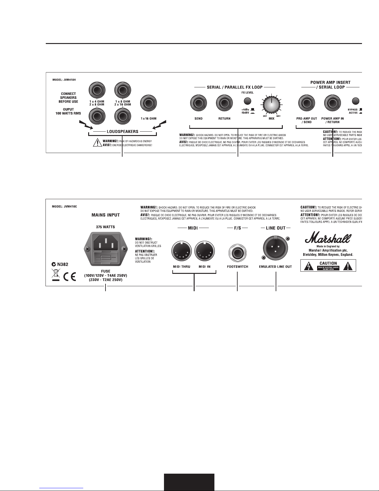
REAR PANEL FUNCTIONS
13. MAINS INPUT
Connects the amplier to the mains
electricity supply.
Note: The MAINS INPUT socket has an
integrated fuse compartment. Ensure that
the value of a replacement fuse matches the
labelling on the amplier rear panel. You
MUST ALWAYS switch the amplier OFF
and disconnect it from the mains electricity
supply before attempting to access the fuse
compartment. If in doubt, contact your
Marshall dealer.
14. MIDI
Connect any external MIDI gear to the
MIDI IN socket. A copy of the signal in this
connector will be available on the MIDI
THRU socket to allow the daisy chaining of
MIDI equipment.
Note: JVM4 only accepts incoming data and it
is not able to send any MIDI commands.
15. FOOTSWITCH
Connect the supplied Stompware®
footswitch using any standard 1/4”
jack mono lead. Using any other type of
footcontroller or footswitch rather than
the one supplied will have no eect and
will be ignored by the amplier.
ENGLISH
JVM410 - COMBO
16151413
JVM410 - HEAD
19 18 17
Page 15

ENGLISH
16. LINE OUT
The pre master volume signal, processed
through a 4x12” speaker cabinet emulator
and electronically balanced, is made
available at this connector.
17. POWER AMP INSERT / SERIAL LOOP
This is a passive loop which connects
right before the master volume in the
signal path. It is a line level loop so it is
recommended to only use high headroom
devices to avoid signal degradaon.
Plugging only into the return jack allows
the use of the JVM4’s power-stage,
overriding the preamp.
MASTER controls and the LINE OUT are
located aer the POWER AMP INSERT/
SERIAL LOOP so it is sll possible to take
advantage of those features when using an
external preamp. The loop can be taken o
the circuit by pressing the BYPASS switch
(the BYPASS/ACTIVE switch cannot be
programmed).
18. SERIAL / PARALLEL FX LOOP
JVM4 is equipped with a SERIAL/
PARALLEL FX LOOP. Connect your
external FX gear input to the SEND jack,
and the FX output to the RETURN jack. As
described previously, the FX loop can be
switched on/o from the front panel and
17 18 19
14 131516
Page 16

ENGLISH
REAR PANEL FUNCTIONS (CONT.)
the amount of eect can be dialled in with
the MIX control.
The +4dBu/-10dBV switch allows you
to congure the loop for use with either
rack equipment (+4dBu seng) or with
stompbox level FX (-10dBV seng).
When MIX is set to WET all of the signal
from external FX goes through the FX
LOOP. Add more direct (unprocessed)
signal by turning MIX towards DRY. This
allows you to mix any amount of the
external FX without losing or degrading
the direct signal quality.
When mixing the WET and DRY signals
the external FX processor’s output should
be congured to remove the direct
(unprocessed) signal or an unpleasant
phasing eect may occur when mixing
it again in the amplier. If the amplier
sounds thin aer connecng external
FX check that no direct signal is being
returned from the processors output.
Note: If the FX loop is switched ON and
the MIX control is set to WET without an
external processor connected, the amplier
will be muted.
19. LOUDSPEAKERS
There are 5 speaker outputs available on
the rear panel. They are labelled according
to the intended impedances:
1 x16 OHM
Connect a 16 Ohm speaker cabinet to this
jack.
1 x 8 OHM/2 x 16 OHM
Connect a single 8 Ohm speaker cabinet or
two 16 Ohm guitar cabinets.
1 x 4 OHM/2 x 8 OHM
Connect a single 4 Ohm speaker cabinet
or two 8 Ohm speaker cabinets.
WARNING: Although JVM4 has 5 speaker
outputs never attempt to connect more
speakers than rated. The safe combinations
are 1x16 Ohm, 1x8 Ohm, 2x16 Ohm,
1x4 Ohm or 2x8 Ohm. Any other speaker
conguration may stress the power amplier
section and in extreme cases may lead to valve
and/or output transformer failure. NEVER
use the JVM410H or JVM410C without a
speaker load.
Page 17

ENGLISH
HINTS AND TIPS
FACTORY RESET
This will erase all the MIDI presets and set
MIDI recepon channel to #1. Please note
that once the memory is erased it cannot
be recovered:
a) Switch the amplier o (POWER switch
OFF).
b) Whilst pressing and holding the CLEAN
CHANNEL/ GAIN switch, switch the
amplier on (POWER switch ON). The 4
channel LEDs will glow red.
c) Release the switch.
d) To conrm the factory reset press the
CRUNCH MODE switch.
e) If you want to abort the reset, press any
other key.
FOOTSWITCH RESET
To restore factory sengs:
a) Unplug the footswitch at any of the
cable sides.
b) Press and hold switch #6 (right switch).
c) Plug in the footswitch cord.
d) Release the switch and the FX led will
start blinking.
e) If you want to erase the footswitch
memory press the switch #5. To keep
the memory press any of the #1 to #4
switches. Please note that once the
memory is erased it cannot be recovered.
f) Release the switch and the footswitch
will synchronise with the amplier.
The factory default is as follows:
FSW #1: CLEAN FSW #2: CRUNCH
FSW #3: OD1 FSW #4: OD2
FSW #5: MASTER FSW #6: REVERB
HINTS
Hint 1:
It is possible to use dierent modes in the
same channel with dierent volumes to
avoid imbalance which can be especially
interesng in the CLEAN channel. To
do this simply create 2 presets in the
footswitch assigning MASTER 1 or
MASTER 2 to any of the modes. If you do
not connect any eect to the SERIAL /
PARALLEL FX LOOP the MIX control can
be used to act like an extra volume control
in any of the channels.
Hint 2:
To have a tuner output mung the
amplier, connect the tuner to the FX
LOOP SEND and select the CLEAN
channel. Turn the MIX control to WET
and switch the FX LOOP on. Store this
preset as described before and label it
for example as ‘tuner’. Obviously in this
conguraon it is not possible to connect
any other eect to the FX LOOP.
Hint 3:
A note about using 2 heads simultaneously
– The suggested procedure is connect the
‘master’ head PREAMP OUT to the ‘slave’
head POWER AMP IN and switch the
POWER AMP INSERT to ACTIVE in the
‘slave’ amplier.
In order to track the MASTER volume
sengs in both heads it is suggested to
use MIDI control with both ampliers
programmed in the same way. Connect
the MIDI IN of one of the ampliers to
the MIDI THROUGH of the other and
the pedalboard or MIDI equipment to the
remaining MIDI IN.
Page 18

AVERTISSEMENT ! CONSIGNES DE SÉCURITÉ IMPORTANTES
FRANÇAIS
AVERTISSEMENT !
Avant d'aller plus loin, vérier que votre
amplicateur est compable avec votre alimentaon
électrique. En cas de doute, s'adresser à un
technicien qualié ; votre vendeur Marshall est en
mesure de vous conseiller à ce sujet.
ENTRÉE SECTEUR ET FUSIBLE :
La tension nominale d'entrée spécique
correspondant à votre amplicateur est indiquée
sur le panneau arrière de l'amplicateur.
Votre amplicateur est fourni avec un cordon
d'alimentaon détachable à brancher dans la PRISE
SECTEUR sur le panneau arrière de l'amplicateur
(Fonctions panneau arrière #13). Le type et la valeur
correcte des fusibles secteur sont indiqués sur le
panneau arrière de l'amplicateur. NE JAMAIS
tenter de dériver le fusible ou d'installer un fusible
dont le type ou la valeur ne correspondent pas.
TRANSPORT DE VOTRE ÉQUIPEMENT :
Vérier que votre amplicateur est éteint et
débranché de l'alimentaon secteur et que tous
les câbles pouvant être débranchés ont été
déconnectés de l'équipement avant de déplacer
l'amplicateur.
INFORMATIONS IMPORTANTES RELATIVES À
L'INSTALLATION :
1. En cas d'ulisaon de la tête JVM410H ou du
combo JVM410C avec un caisson haut-parleur
supplémentaire, s'assurer que les haut-parleurs sont
connectés aux jacks haut-parleurs d'impédance
correcte sur le panneau arrière de l'amplicateur.
Consulter le guide d'ulisaon des HAUTPARLEURS contenu dans le présent guide pour plus
d'informaons concernant les correspondances
d'impédance (Fonctions panneau arrière #19).
AVERTISSEMENT Le non-respect des consignes
ci-dessus risque d'endommager votre amplicateur.
Lors du raccordement d'un caisson haut-parleur,
veiller à uliser un câble pour haut-parleur correct.
Ne jamais uliser à cet eet un câble de guitare
blindé.
2. Vérier que le commutateur d'ALIMENTATION
(Fonctions panneau avant #12) est en posion OFF
(Arrêt).
3. Brancher le câble d'alimentaon fourni à
l'ENTRÉE ALIMENTATION (Fonctions panneau arrière
#13) d'abord, puis sur la source d'alimentaon
électrique.
4. Vérier que les commandes MASTER 1 et
MASTER 2 sur le panneau avant sont réglées sur
zéro (Fonctions panneau avant #7).
5. Brancher votre guitare dans une prise jack
d'ENTRÉE sur le panneau avant (Fonctions panneau
avant #1).
6. Vérier que l'interrupteur STANDBY (Veille)
(Fonctions panneau avant #11) est en posion OFF
(Arrêt).
7. Régler l'interrupteur d'ALIMENTATION sur
MARCHE (I) sur le panneau avant et aendre deux
minutes avant de passer au point 8.
8. Acver l'amplicateur en réglant l'interrupteur
STANDBY sur ON (Marche).
9. Augmenter le volume sur le niveau souhaité :
l'amplicateur est prêt.
LIRE ATTENTIVEMENT CE MANUEL AVANT DE BRANCHER
L'ÉQUIPEMENT.
SUIVRE TOUTES LES INSTRUCTIONS ET TENIR COMPTE DES
AVERTISSEMENTS.
CONSERVER CES INSTRUCTIONS
Page 19

FRANÇAIS
Cet appareil est conforme à la pare 15 des Régulaons FCC. L’exploitaon est autorisée aux deux
condions suivantes :
1. Cet appareil ne doit pas produire de brouillage, et
2. l’appareil doit accepter tout brouillage radioélectrique subi, même si le brouillage est suscepble
d’en compromere le fonconnement.
Cet équipement a été testé et trouvé conforme aux limites applicables à un appareil numérique de Classe B,
suivant la Pare 15 des Règles FCC. Ces limites sont conçues pour apporter une protecon raisonnable
contre les interférences nuisibles dans un environnement résidenel.
Cet équipement génère, ulise, et peut émere de l’énergie de fréquence radio et, s’il n’est pas installé et
ulisé conformément aux consignes, risque de causer des interférences nuisibles aux communicaons radio.
Il n'existe toutefois aucune garane que ces interférences n'auront pas lieu dans une installaon parculière.
Si cet équipement cause des interférences nuisibles à la récepon radiophonique ou télévisée, ce qui peut
être établi en éteignant et rallumant l'équipement, l'ulisateur est encouragé à prendre une plusieurs des
mesures suivantes pour résoudre ces interférences :
• Réorienter ou déplacer l'antenne de récepon.
• Augmenter la distance entre l'équipement et le récepteur.
• Brancher l'équipement dans une sore circuit diérente de celle dans laquelle le récepteur est
branché.
• Demander l'aide de son revendeur ou d'un technicien radio/TV expérimenté.
MISE EN GARDE : Tout changement ou modicaon eectué sans avoir été expressément approuvé par la
pare responsable de sa conformité risque d'annuler le droit d'exploitaon de l'équipement par son
ulisateur.
Cet équipement est conforme aux normes CAN ICES-3(B)/NMB-3(B)
DÉCLARATION DE CONFORMITÉ
Tête JVM410H Combo JVM410C
Puissance (RMS) 100W 100W
Lampes 5x ECC83 + 4x EL34 5x ECC83 + 4x EL34
Guitare principale - Impédance d'entrée 470kΩ 470kΩ
Sortie émulée - Niveau +4dBu +4dBu
Niveau d'envoi FX (Effet) - Sélectionnable -10dBV, +4dBu -10dBV, +4dBu
Poids 22kg 34,5kg
Taille (mm) W, H, D 750 x 310 x 215 690 x 510 x 265
SPÉCIFICATIONS TECHNIQUES
Page 20

FRANÇAIS
INTRODUCTION
Après des débuts modestes en 1962, Marshall s'est hissé au rang d'icône mondiale. Indissociables des
sons de la musique rock et blues rock, la puissance légendaire et le ton inimitable des amplicateurs
Marshall s'illustrent sur de nombreux enregistrements studio et live des cinquante dernières années. Les
amplicateurs Marshall ont résisté au temps, et certains de nos classiques des années '60, '70, '80 & '90 sont
encore fabriqués à l'usine Marshall de Bletchley, en Angleterre.
Au l des ans, Marshall s'est forgé la réputaon de fabriquer des amplicateurs robustes, solides, ables
à la qualité sonore exceponnelle pour tous les guitaristes, et nos valeurs n'ont pas changé, cela demeure
notre objecf premier. Grâce à l'experse de nos travaux de R&D et à une concepon audacieuse, nous
connuons d'innover, forts de notre héritage et de notre réputaon de numéro un des fabricants d'amplis
britanniques.
Les amplis à lampes JVM410H et JVM410C sont fabriqués en Angleterre par une équipe qualiée et
spécialisée dont le talent et le sens du détail produisent des amplicateurs et caissons haut-parleurs parmi
les plus emblémaques et les plus appréciés au monde.
La très appréciée Série JVM4 est à la pointe de six décennies d'évoluon tonale et fonconnelle ; cee
évoluon répond non seulement à notre désir de fabriquer les meilleurs amplicateurs du monde, mais
aussi à l'enthousiasme de nos clients, arstes professionnels et amateurs. Chez Marshall, nous comprenons
la nécessité de produire le son, la sensaon et la fonconnalité justes pour vous inspirer et contribuer à
l'exploitaon de tout votre potenel créaf.
La Série JVM4 comprend 4 canaux tonalement indépendants, chacun équipé de 3 modes, pour une palee
tonale très riche au service de votre son. Embarquant en outre une boucle FX (Eet), deux volumes Master
et quatre Reverbs de canaux indépendants, la série JVM4 est aussi très polyvalente.
Le contrôle de la gamme tonale et de la fonconnalité de JVM4 nécessite un système de pédalier unique.
La pédale programmable à 6 boutons Stompware® vous permet de canaliser la puissance de JVM4, pour
un réel contrôle de votre son pendant le jeu, soit en acvant directement les foncons panneaux, soit en
programmant des groupes de paramètres des panneaux pour former des Préréglages enregistrés sur un
bouton unique du pédalier.
Nous espérons sincèrement que votre amplicateur de Série JVM4 vous deviendra indispensable, et vous
apportera le son légendaire de Marshall pour des années à venir, quel que soit votre type de jeu.
Merci d'avoir choisi Marshall.
L'équipe Marshall
Page 21

FRANÇAIS
PRÉSENTATION
CANAUX, MODES & MÉMOIRE
Voici l'amplicateur JVM4 à lampes, 4 canaux,
100 Wa (Tête JVM410H ou combo JVM410C
2x12”). Ses 4 canaux intègrent 3 modes, pour vous
orir au total 12 modes au choix, chacun doté
d'une structure de gain unique. Bien que le panneau
avant présente 28 boutons de commandes et
8 interrupteurs à voyant LED, le JVM4 est facile à
comprendre et fonconne grâce à une disposion
extrêmement logique des panneaux avant et arrière.
Le panneau avant conent des ensembles de
commandes dédiés pour chacun de ses 4 canaux CLEAN, CRUNCH, OD1 & OD2 - en plus des
secons MASTER et REVERB. Chaque canal
conent les commandes habituelles, VOLUME,
BASS, MIDDLE, TREBLE et GAIN. La secon
REVERB consiste en 4 commandes de niveau, une
pour chaque canal, tandis que la secon MASTER
comprend 2 volumes Master aconnables par
pédalier : MASTER 1/MASTER 2, ainsi que les
commandes master RESONANCE et PRESENCE qui
s'appliquent aux 4 canaux à la fois.
Chacun des 4 canaux dispose de 3 modes
aconnables. On les séleconne via le commutateur
MODE dédié à chaque canal. Pour séleconner un
canal, appuyer sur son commutateur MODE dédié ou
poser le pied sur le pédalier à 6 boutons Stompware®
fourni. Pour faire déler les 3 modes du canal
séleconné, connuer d'appuyer sur le commutateur
correspondant : la couleur de la LED sur le pédalier
passe du vert à l’orange, puis au rouge, puis de
nouveau au vert. De cee manière, on augmente le
niveau de gain d'un cran à chaque fois (le rouge est le
plus élevé, le vert est le plus faible pour chaque canal)
et on change la tonalité du canal.
Lorsque vous quiez puis séleconnez à nouveau
un canal, il reproduit automaquement le dernier
mode acf ; les 4 canaux mémorisent leur mode
le plus récent jusqu'à la modicaon suivante. Par
exemple, si vous séleconnez le mode orange pour
le canal CRUNCH, et si vous passez ensuite au canal
CLEAN, lorsque vous séleconnez à nouveau le canal
CRUNCH, il est encore en mode orange.
En plus de la sélecon du canal et du mode, les
autres fonconnalités aconnables par le panneau
avant et par le pédalier sont les suivantes : REVERB
(marche/arrêt), MASTER 1 & MASTER 2, et SERIES/
PARALLEL FX LOOP (Boucle FX (Eet) parallèle/
de série) (marche/arrêt). Ces 3 foncons sont aussi
mémorisées par chaque mode.
En résumé, chacun des 12 modes du JVM4 mémorise
ses réglages les plus récents de REVERB, FX LOOP
et volume MASTER. En outre, les réglages des modes
peuvent aussi être enregistrés et récupérés sur l'un
des 128 emplacements disponibles via MIDI.
PÉDALIER À 6 BOUTONS STOMPWARE®
Les modèles JVM410H et JVM410C sont fournis
équipés d'un pédalier programmable à 6 boutons
Stompware®, qui peut être branché à l'ampli via
n'importe quel câble de guitare standard.
Remarque: Le câble de pédalier fourni est non blindé et
n'est pas adapté à la guitare.
Le pédalier comprend 7 voyants LED indiquant
CLEAN, CRUNCH, OD1, OD2, MASTER, REVERB
et FX. Les LED de chacun des 4 canaux sont en 3
couleurs : vert, orange et rouge, pour une indicaon
visuelle du canal et du mode séleconnés ainsi que
du statut MASTER, REVERB et FX LOOP.
Le pédalier Stompware® vous permet d'aribuer
à n'importe lequel de ses 6 boutons la foncon
de récupérer instantanément n'importe quelle
foncon du panneau avant (Mode commutaon de
mémorisaon - Switch store) ou le réglage complet
du canal (Mode mémoire préétablie - Preset store)
dans n'importe quel ordre ou n'importe quelle
combinaison.
Page 22

FRANÇAIS
MODE COMMUTATION DE MÉMORISATION
(SWITCH STORE)
En mode de commutaon de mémorisaon,
on aribue à un bouton du pédalier la foncon
d'un des commutateurs du panneau avant de
l'ampli : CHANNEL/MODE (CANAL/MODE),
REVERB marche/arrêt, MASTER 1/2 et FX LOOP
(BOUCLE FX - Eet) marche/arrêt.
Si un bouton du pédalier est aribué à un canal en
parculier, une fois acvé le bouton du pédalier
permet de faire déler les trois modes, comme le
ferait le commutateur correspondant sur le panneau
avant.
MODE MÉMOIRE PRÉÉTABLIE (PRESET STORE)
En mode de mémoire préétablie, chaque bouton
du pédalier peut être programmé pour acver
instantanément une combinaison d'opons de
commutateurs du panneau avant, pour former un
Préréglage. Par exemple, vous pouvez programmer le
pédalier de telle manière que :
Bouton #1 = canal CRUNCH, mode vert avec volume
MASTER ‘1’, REVERB sur ‘marche’ et Boucle FX
(Eet) sur ‘arrêt’.
Bouton #2 = canal CLEAN, mode rouge avec volume
MASTER ‘2’, REVERB sur ‘arrêt’ et Boucle FX (Eet)
sur ‘marche’.
Tous les paramètres de préréglages sont mémorisés
dans le pédalier ; cela signie qu'il vous sut de le
brancher à n'importe quel amplicateur JVM4 et pour
récupérer instantanément les paramètres enregistrés
dans votre pédalier.
Vous trouverez plus d'informaons sur la
programmaon de votre pédalier plus loin dans ce
manuel (Fonction panneau avant #10).
AMPLI DE PUISSANCE
L'étage de puissance du JVM4 100 Wa se fonde sur
celui des amplicateurs Superlead 1959 et JCM800
2203, auteurs du légendaire rugissement Marshall.
Il a été ajusté pour s'adapter à la palee tonale des
canaux et modes du JVM4. La secon de l'ampli
de puissance inclut les commandes PRESENCE et
RESONANCE pour vous aider à façonner le ton
d'ensemble de votre amplicateur JVM4.
Votre JVM4 est aussi équipé d'un mode
d'enregistrement silencieux. Lorsque l'interrupteur
STANDBY (Veille) est sur OFF (Arrêt), l'étage
de puissance est désacvé, mais le reste de
l'amplicateur demeure complètement opéraonnel.
REVERB
Les modèles JVM410H et JVM410C sont équipés
d'une reverb de qualité studio, acheminée en
parallèle du signal principal et mixée via une lampe.
Lorsque la reverb est acvée, il ne se produit aucune
dégradaon du signal direct, et lorsqu'elle est sur
"arrêt", elle est tout simplement exclue du circuit.
Chacun des canaux du JVM4 intègre sa propre
commande de REVERB dédiée.
La commutaon REVERB a été conçue pour éviter
une coupure brutale de la queue de la reverb, si bien
que lorsqu'on passe d'un canal à un autre ou si l'on
éteint la reverb, sa queue s'eace progressivement.
STANDBY (VEILLE) & ENREGISTREMENT SILENCIEUX
(Fonction panneau avant #11)
Lorsque l'amplicateur est sur STANDBY (Veille)
OFF (Arrêt), toute la secon du préampli connue
de fonconner à sa tension nominale tandis que
l'étage de puissance reste en état de veille. Cela
permet d'uliser l'amplicateur pour l'enregistrement
silencieux ou pour le préampli au moyen de la sore
de ligne émulée, EMULATED LINE OUT (Fonction de
panneau arrière #16).
PRÉSENTATION (SUITE)
Page 23

FRANÇAIS
REMARQUES
Page 24

FONCTIONS DU PANNEAU AVANT
FRANÇAIS
1. ENTRÉE
Prise jack d'entrée pour votre câble de guitare.
Uliser un câble blindé de bonne qualité pour éviter
toute friture.
2. CANAL CLEAN
CLEAN EN MODE VERT : C'est le mode le plus clean
des trois, et dans la droite ligne des amplis clean
tradionnels, il ulise un circuit simple et direct, qui
conserve toute la pureté du signal. Sous ce mode, la
commande de VOLUME du canal est exclue du
circuit, comme sur les amplicateurs vintage du
même type. C'est le seul mode dans ce cas.
CLEAN EN MODE ORANGE : En ajoutant un autre
étage de gain après le stack de son, on obent un
son plus punchy, facile à pousser en overdrive.
Comme pour le reste des modes, la commande de
VOLUME du canal est acve.
CLEAN EN MODE ROUGE : Ce mode pousse encore
plus le son clean d'origine et le transforme en un
canal à gain pseudo élevé, avec en plus un autre
étage de gain après le stack de son.
POWER STANDBY
/ SILENT RECORDING
REVERBMASTER
FOOTSWITCH/
MIDI PROGRAM
FX LOOP
TREBLE
0 10
TREBLE
0 10
MIDDLE
0 10
MIDDLE
0 10
BASS
0
10
BASS
0
10
VOLUME
0 10
VOLUME
0 10
RVB
CLEAN
0 10
RVB CRUNCH
0 10
RVB
OD1
0 10
RVB OD2
0 10
MASTER
1
0 10
PRESENCE
0 10
MASTER
2
0 10
RESONANCE
0 10
MASTER REVERB
OD1
OD2
O
I
OFF
ON
JVM410H - PANNEAU AVANT
89
10 7 6
1112
GAIN
0 10
VOLUME
INPUT
0 10
OD2
MODE
CLEAN
MODE
CRUNCH
MODE
OD1
MODE
BASS
0 10
BASS
0 10
MIDDLE
0 10
MIDDLE
0 10
TREBLE
0 10
TREBLE
0 10
VOLUME
(Orange & Red)
0 10
GAIN
0 10
VOLUME
0 10
VOLUME
0 10
BASS
0
10
BASS
0
10
MIDDLE
0 10
MIDDLE
0 10
TREBLE
0 10
TREBLE
0 10
GAIN
0 10
GAIN
0 10
CRUNCH
0 10
RVB CLEAN
0 10
OD2
OD1CLEAN
CRUNCH
JVM410C - PANNEAU AVANT
1 42
3 5
Page 25

FRANÇAIS
Dans la tradion des amplis clean classiques d'antan,
les trois modes de ce canal comprennent ce que
l'on appelle un stack de ton pré-gain (c'est-à-dire
que le réseau tonal se trouve avant l'étage de
gain principal du canal). L'inverse (c'est-à-dire un
réseau tonal placé après l'étage de gain principal)
est caractérisque de la plupart des amplicateurs
Marshall et par conséquent, les commandes tonales
du canal CLEAN fonconnent un peu diéremment
de ce qu'on pourrait penser ; outre le contrôle du
ton du canal, elles déterminent aussi sa réacon en
termes de gain, en vous permeant de façonner la
distorsion du signal.
Par exemple, si vous réglez la commande MIDDLE
sur des paramètres de GAIN plus élevés, c'est là
que se concentrera votre distorsion, produisant un
son blues/rock tradionnel. Par ailleurs, du fait de
la topologie "tonalité puis gain" des canaux, lorsque
vous réglez sur un GAIN élevé (surtout pour le mode
rouge), il pourrait vous sembler que les commandes
tonales ne produisent pas grand-chose, ou que leur
distorsion est excessive. Cela est dû au fait que
le signal est distordu après l'étage de ton, ce qui
réduit l'ecacité des commandes BASS, MIDDLE et
TREBLE.
GAIN
0 10
GAIN
INPUT
0 10
OD1
MODE
CLEAN
MODE
CRUNCH
MODE
OD2
MODE
TREBLE
0 10
TREBLE
0 10
MIDDLE
0 10
MIDDLE
0 10
BASS
0 10
BASS
0 10
VOLUME
(Orange & Red)
0 10
VOLUME
0 10
GAIN
0 10
GAIN
0 10
TREBLE
0 10
TREBLE
0 10
MIDDLE
0 10
MIDDLE
0 10
10
10
OD1
OD2
CLEAN
CRUNCH
135
4 2
POWERSTANDBY
/ SILENT RECORDING
REVERB
MASTER
FX LOOP
FOOTSWITCH/
MIDI PROGRAM
VOLUME
0 10
VOLUME
0 10
10
10
RVB
OD2
0 10
RVB OD1
0 10
RVB
CRUNCH
0 10
RVB CLEAN
0 10
RESONANCE
0 10
MASTER 2
0 10
PRESENCE
0 10
MASTER 1
0 10
MASTER
REVERB
O
I
OFF
ON
10 11 127
6 8 9
Page 26

FRANÇAIS
3. CANAL CRUNCH
Ici, le JVM4 revient à un circuit préampli Marshall
plus caractérisque de "gain puis tonalité". Cela
s'applique aussi aux canaux OD1 et OD2.
CRUNCH EN MODE VERT : Ce mode partage
la topologie de préampli des modèles PlexiTM
JTM45/1959 classiques de Marshall (c'est-à-dire
gain + gain + tonalité), mais avec un peu plus de gain
que n'en présentaient les originaux.
CRUNCH EN MODE VERT : Ce mode évoque
l'amplicateur JCM800 2203, un incontournable du
hard rock. La structure du gain est la suivante : gain
+ gain + gain + tonalité.
CRUNCH EN MODE ROUGE : Il partage la topologie
du mode orange, mais avec plus de gain, pour un
son qui rappelle un JCM800 au son traqué.
4. CANAL OD1
OD1 EN MODE VERT : Il est très proche du son de
style JCM800 traqué produit par le mode crunch
rouge, ce qui vous permet de séleconner deux sons
crunch clairement disncts mais similaires si vous le
souhaitez : un sur chaque canal.
OD1 EN MODE ORANGE : On ajoute encore un
étage de gain par rapport au mode vert de OD1, ce
qui produit un son idéal pour des solos de chant ou
des tons hard rock / heavy metal.
OD1 EN MODE ROUGE : Rajoute du gain à l'OD1
orange pour un son Marshall à gain élevé.
5. CANAL OD2
Ce canal est similaire au canal OD1 mais avec
encore plus de gain et un réseau tonal légèrement
diérent, dont la commande de Middle est réduite
à environ 500 Hz au lieu de la valeur plus habituelle
pour Marshall de 650 Hz. On obent donc 3 modes
de gain élevé qui se prêtent idéalement aux solos et
aux tons métalliques des rythmes modernes.
SECTION MASTER
6. REVERB
En appuyant sur le bouton REVERB, on allume et on
éteinte la reverb sur le canal séleconné.
Chaque canal possède sa propre commande de
reverb, ce qui permet de régler le niveau de reverb
(RVB) pour chaque canal individuellement : RVB
CLEAN, RVB CRUNCH, RVB OD1 et RVB OD2.
7. MASTER 1 / MASTER 2
Ce sont les commandes de volume master de
l'amplicateur. Elles peuvent être aribuées
individuellement à chacun des modes selon vos
préférences, et leur réglage est enregistré.
8. PRESENCE ET RESONANCE
Ces commandes sont des foncons d'étage
de puissance et ne produisent d'eet que
lorsque vous jouez sur haut-parleur (et non pas
en ENREGISTREMENT SILENCIEUX). Elles
déterminent la réacon de l'amplicateur aux
haut-parleurs connectés, et le degré de contrôle que
l'amplicateur exerce sur ces haut-parleurs.
En augmentant la commande RESONANCE, on met
l'accent sur la résonance du haut-parleur, pour une
meilleure réponse des basses et des médiums plus
profond. De même, en augmentant la commande
PRESENCE, on met l'accent sur les fréquences
hautes du haut-parleur, pour un son plus vif et plus
"présent".
PRESENCE et RESONANCE constuent un puissant
égalisateur de l'étage de puissance, ouvrant la porte à
des réacons qui vont d'une forme en "
" lorsqu'elles
sont complètement éteintes, pour un eet boost
moyen, à une forme en "v" lorsqu'on les tourne dans
le sens horaire, pour un son plus modulé. Encore
une fois, l'ecacité de ces commandes dépend
largement du type de haut-parleurs connectés. Il
convient de prendre soin de ne pas dépasser les
limites d’amplitude des cônes de haut-parleur sur les
réglages de résonance élevée.
FONCTIONS DU PANNEAU AVANT (SUITE)
Page 27

FRANÇAIS
9. BOUCLE FX
En appuyant sur le bouton FX LOOP (Boucle FX Eet), on allume et on éteint la boucle FX sur le
canal séleconné.
La boucle FX (Eet) est programmable et comprend
une commande MIX sur le panneau arrière. La
boucle FX (Eet) est située après le préampli sur la
chaîne du signal, juste avant la reverb et les circuits
de boucle en série. En appuyant sur le commutateur
FX LOOP (Boucle FX - Eet), on acve cee boucle
FX.
10. PÉDALIER / PROGRAMMATION MIDI
Ce commutateur remplit deux foncons :
En l'enfonçant une fois, on accède au mode
FOOTSWITCH PROGRAM (Programmaon
pédalier). Il est indiqué par un voyant rouge xe.
En l'enfonçant deux fois, on accède au mode MIDI
PROGRAM (Programmaon MIDI). Il est indiqué par
un voyant rouge clignotant.
PROGRAMMATION ET UTILISATION DU PÉDALIER
La série JVM4 intègre la technologie de pédalier
Stompware®. Le raccordement du pédalier à
l'amplicateur nécessite un câble de jack en
jack 1/4”. N'importe quel câble de guitare est
compable, et concrètement sa longueur n'est pas
limitée.
Lorsque le commutateur FOOTSWITCH / MIDI
PROGRAM sur le panneau avant est sur "arrêt", le
pédalier fonconne en mode normal et exécute les
commandes lorsqu'on appuie sur un bouton.
Si vous acvez le mode FOOTSWITCH PROGRAM
(LED rouge) vous pouvez programmer la pédale,
mais malgré cela le pédalier et l'amplicateur
demeurent complètement opéraonnels, à la seule
diérence près que les commandes sont exécutées
lorsqu'on relâche un bouton, contrairement au mode
normal.
Le pédalier à 6 boutons Stompware® fonconne
sur 2 modes : Preset Store (Mémoire préétablie) et
Switch Store (Commutaon de mémorisaon).
MODE MÉMOIRE PRÉÉTABLIE
N'importe lequel des boutons du pédalier peut
être conguré pour mémoriser le statut actuel
de l'amplicateur. Le statut actuel du canal, du
master, de la boucle FX (Eet) et de la reverb sont
mémorisés et récupérés lorsque le bouton de
pédalier correspondant est enfoncé.
Pour mémoriser le statut actuel :
a) Régler l'amplicateur sur le mode FOOTSWITCH
PROGRAM (voyant rouge ALLUMÉ).
b) Appuyer sur le commutateur souhaité et le
maintenir enfoncé pendant environ 3 secondes.
c) Le voyant LED FX (Eet) du pédalier clignote deux
fois, indiquant que le préréglage a été enregistré.
MODE COMMUTATION DE MÉMORISATION
(SWITCH STORE)
N'importe lequel des boutons du pédalier peut être
conguré pour commander les commutateurs du
panneau avant, et l'amplicateur réagit exactement
de la même manière que si vous acviez les
commutateurs sur le panneau avant.
Tous les commutateurs du panneau avant peuvent
être mis en correspondance avec n'importe lequel
des boutons, sans restricon. La seule excepon est
la touche FOOTSWITCH / MIDI PROGRAM, qui ne
peut pas être aribuée au pédalier.
Pour aribuer n'importe lequel des boutons
du panneau avant (sauf FOOTSWITCH / MIDI
PROGRAM) à n'importe lequel des boutons du
pédalier :
a) Régler l'amplicateur sur le mode FOOTSWITCH
PROGRAM (voyant rouge ALLUMÉ).
Page 28

FRANÇAIS
FONCTIONS DU PANNEAU AVANT (SUITE)
b) Maintenir enfoncé le bouton choisi.
c) Tout en maintenant le bouton enfoncé, en moins
de 3 secondes, appuyer sur le commutateur du
panneau avant que vous souhaitez lui aribuer.
c) Le voyant LED FX (Eet) du pédalier clignote deux
fois, indiquant que le préréglage a été enregistré.
e) Dorénavant, le bouton séleconné agit
exactement de la même manière que si vous
appuyiez sur le bouton correspondant sur le
panneau avant.
Les boutons du panneau avant et les préréglages
peuvent être aribués comme vous le souhaitez,
sans restricon et dans n'importe quel ordre
(toujours à l'excepon du commutateur
FOOTSWITCH / MIDI PROGRAM).
La conguraon du pédalier est mémorisée dans le
pédalier lui-même, et non pas dans l'amplicateur.
Le reparamétrage de l'amplicateur n'aura pas
d'incidence sur la conguraon du pédalier.
Le pédalier peut être déplacé à chaud et se
synchronise avec n'importe quel amplicateur
JVM4 après connexion. Toutefois, il est conseillé de
brancher le câble du pédalier d'abord sur la pédale,
puis sur l'amplicateur.
FONCTIONNEMENT MIDI
En appuyant sur le bouton FOOTSWITCH / MIDI
PROGRAM deux fois, on place l'amplicateur en
mode d'aente MIDI ; le voyant clignote jusqu'à ce
qu'une commande de modicaon de programme
MIDI valide soit reçue.
À la récepon d'une commande de modicaon de
programme MIDI, l'amplicateur enregistre le statut
actuel (réglages de canal + FX + reverb + master)
sous le numéro de programme MIDI reçu. On peut
mémoriser jusqu'à 128 préréglages MIDI diérents.
Pour quier ce statut sans aendre l'arrivée de
données MIDI entrantes, appuyer à nouveau sur le
bouton FOOTSWITCH / MIDI PROGRAM.
Par défaut, l'amplicateur est conguré pour écouter
le canal MIDI #1, mais il peut être modié pour
permere d'écouter les 16 canaux MIDI, de la
manière suivante :
a) Éteindre l'amplicateur (interrupteur
d'ALIMENTATION, et non pas STANDBY).
b) Maintenir enfoncé le bouton choisi
FOOTSWITCH / MIDI PROGRAM.
c) Allumer l'amplicateur.
d) Relâcher le bouton FOOTSWITCH / MIDI
PROGRAM : le voyant LED se met à clignoter.
e) Envoyer toute commande MIDI au moyen
du pédalier MIDI ou de n'importe quel autre
équipement MIDI.
f) L'amplicateur détecte quel canal est entré et
se congure pour écouter exclusivement ce canal
MIDI.
g) Désormais, le préréglage MIDI que vous aviez
précédemment mémorisé ne s'acve que sur le
nouveau canal, quel que soit le canal que vous
avez ulisé avant ; cela permet une reconguraon
rapide en cas de conit MIDI avec n'importe quel
autre équipement périphérique.
Remarque: Pour quitter la sélection de canal MIDI
sans effectuer aucune action, appuyer sur le bouton
FOOTSWITCH / MIDI PROGRAM tout en attendant les
données MIDI.
11. STANDBY (VEILLE) & SILENT RECORDING
(ENREGISTREMENT SILENCIEUX)
L'interrupteur de veille STANDBY s'ulise en
conjoncon avec l'interrupteur d'ALIMENTATION
pour "faire chauer" l'ampli avant ulisaon et
prolonger la durée de vie des lampes de sore.
FRANÇAIS
Lorsque l'amplicateur est en STANDBY (Veille -
Arrêt), toute la secon du préampli connue de
fonconner à sa tension nominale tandis que l'étage
de puissance reste en état de veille. Cela permet
d'uliser l'amplicateur pour l'enregistrement
silencieux ou pour le préampli au moyen de la sore
de ligne émulée, EMULATED LINE OUT (Foncon
de panneau arrière #16).
Ce n'est que lorsque l'amplicateur est en "veille"
(Interrupteur STANDBY sur OFF - Arrêt) que
l'amplicateur peut être ulisé sans charge de haut-
parleur. Toujours vérier qu'une charge de haut-
parleur est branchée lorsque vous quiez le mode
SILENT RECORDING (Enregistrement silencieux),
c'est-à-dire lorsque vous acvez l'interrupteur
STANDBY pour acver l'amplicateur.
12. ALIMENTATION
Interrupteur d'alimentaon marche/arrêt.
Page 29

FRANÇAIS
Lorsque l'amplicateur est en STANDBY (Veille Arrêt), toute la secon du préampli connue de
fonconner à sa tension nominale tandis que l'étage
de puissance reste en état de veille. Cela permet
d'uliser l'amplicateur pour l'enregistrement
silencieux ou pour le préampli au moyen de la sore
de ligne émulée, EMULATED LINE OUT (Foncon
de panneau arrière #16).
Ce n'est que lorsque l'amplicateur est en "veille"
(Interrupteur STANDBY sur OFF - Arrêt) que
l'amplicateur peut être ulisé sans charge de hautparleur. Toujours vérier qu'une charge de hautparleur est branchée lorsque vous quiez le mode
SILENT RECORDING (Enregistrement silencieux),
c'est-à-dire lorsque vous acvez l'interrupteur
STANDBY pour acver l'amplicateur.
12. ALIMENTATION
Interrupteur d'alimentaon marche/arrêt.
Page 30
FONCTIONS PANNEAU ARRIÈRE
13. ENTRÉE SECTEUR
Raccorde l'amplicateur à la source d'alimentaon
secteur.
Remarque: La prise d'ENTRÉE SECTEUR comporte
un compartiment fusible intégré. Vérier que la valeur
des fusibles de rechange correspond à l'étiquette sur
le panneau arrière de l'amplicateur. Vous DEVEZ
TOUJOURS éteindre et débrancher l'amplicateur avant
d'accéder au compartiment fusible. En cas de doute,
demander conseil à votre revendeur Marshall.
14. MIDI
Brancher n'importe quel équipement MIDI à la
prise d'entrée MIDI IN. Une copie du signal sur ce
connecteur sera disponible sur la prise MIDI THRU
pour permere le montage en série d'équipements
MIDI.
Remarque: JVM4 n'accepte que les données entrantes, et
ne peut pas envoyer de commandes MIDI.
15. PÉDALE
Connectez le pédalier Stompware® fourni au moyen
de n'importe quel câble mono jack 1/4”. L'ulisaon
d'un autre type de pédale ou de pédalier que celui
fourni ne produira aucun eet et sera ignoré par
l'amplicateur.
16. SORTIE DE LIGNE (LINE OUT)
Le signal de volume PRE MASTER, traité via
un émulateur de caisson haut-parleur 4x12" et
FRANÇAIS
JVM410 - COMBO
16151413
JVM410 - TÊTE
19 18 17
Page 31

FRANÇAIS
symétrique, est disponible sur ce connecteur.
17. FICHE AMPLI DE PUISSANCE / BOUCLE SÉRIE
Il s'agit d'une boucle passive connectée juste avant
le volume master sur le chemin du signal. C'est une
boucle de niveau de ligne, il est donc recommandé
de n'uliser que des appareils à haute réserve de
gain, pour éviter la dégradaon du signal. En ne la
branchant que dans le jack de retour, on permet
l'ulisaon de l'étage de puissance du JVM4, en
contournant le préampli.
Les commandes MASTER et la sore de ligne
LINE OUT sont placés derrière la FICHE AMPLI
DE PUISSANCE / BOUCLE SÉRIE, il reste donc
possible de proter de ces fonconnalités tout en
ulisant un préampli externe. La boucle peut être
rerée du circuit en appuyant sur le commutateur
BYPASS (Contournement) (le commutateur BYPASS/
ACTIVE - Contournement / Acf - ne peut pas être
programmé).
18. BOUCLE FX (EFFET) SÉRIE / PARALLÈLE
JVM4 est équipé d'une BOUCLE FX (EFFET) SÉRIE /
PARALLÈLE. Brancher votre entrée d'équipement FX
(Eet) externe au jack d'ENVOI, et la sore FX (Eet)
au jack de RETOUR. Comme décrit précédemment,
la boucle FX (Eet) peut être acvée et désacvée à
parr du panneau avant, et la dose d'eet peut être
choisie via la commande MIX.
17 18 19
14 131516
Page 32

FRANÇAIS
FONCTIONS DU PANNEAU ARRIÈRE (SUITE)
Le commutateur +4dBu/-10dBV vous permet de
congurer la boucle pour une ulisaon avec un
équipement FX (Eet) en rack (réglage +4dBu) ou de
niveau stompbox (réglage -10dBV).
Lorsque MIX est réglé sur WET (Mouillé), l'intégralité
du signal du FX externe traverse la BOUCLE FX
(Eet). Ajouter plus de signal direct (non traité) en
tournant la commande MIX vers DRY (Sec). Cela vous
permet de mélanger n'importe quelle quanté du FX
externe sans perdre ni dégrader la qualité du signal
direct.
Si vous mélangez les signaux WET et DRY, la sore
du processeur du FX externe doit être congurée
pour supprimer le signal direct (non traité), sans quoi
un eet de phasage déplaisant risque de se produire
lors du mixage dans l'amplicateur. Si le son de
l'amplicateur semble faible après le raccordement
à un FX externe, vériez qu'aucun signal direct ne
revient de la sore du processeur.
Remarque: Si la boucle FX (Effet) est ACTIVÉE et que
la commande MIX est réglée sur WET sans qu'aucun
processeur externe ne soit raccordé, l'amplicateur est
rendu silencieux.
19. HAUT-PARLEURS
5 sores de haut-parleurs sont disponibles sur le
panneau arrière. Elles sont idenées selon les
impédances prévues :
1 x16 OHM
Brancher un caisson haut-parleur 16 Ohm à ce jack.
1 x 8 OHM/2 x 16 OHM
Raccorder un seul caisson haut-parleur 8 Ohm ou
deux caissons de guitare 16 Ohm.
1 x 4 OHM/2 x 8 OHM
Raccorder un seul caisson haut-parleur 4 Ohm ou
deux caissons haut-parleurs 8 Ohm.
AVERTISSEMENT! Même si l'amplicateur JVM4
possède 5 sorties haut-parleurs, ne jamais tenter de
brancher plus de haut-parleurs que la quantité prescrite.
Les combinaisons sans danger sont 1x16 Ohm, 1x8
Ohm, 2x16 Ohm, 1x4 Ohm ou 2x8 Ohm. Toute autre
conguration des haut-parleurs risquerait de placer trop
de contrainte sur la section ampli, et dans certains cas
extrêmes pourrait même causer une panne de la lampe
et/ou du transformateur de sortie. Ne JAMAIS utiliser
JVM410H ou JVM410C sans charge de haut-parleur.
Page 33

FRANÇAIS
TRUCS ET ASTUCES
RÉINITIALISATION DES PARAMÈTRES D'USINE
Eace tous les préréglages MIDI et règle le canal de
récepon MIDI sur #1. Notez qu'une fois la mémoire
eacée, elle n'est plus récupérable.
a) Éteindre l'amplicateur (interrupteur
d'ALIMENTATION sur ARRÊT).
b) Tout en enfonçant et en maintenant enfoncé le
commutateur CLEAN CHANNEL/ GAIN, allumer
l'amplicateur (interrupteur d'ALIMENTATION sur
MARCHE). Les 4 voyants LED des canaux s'allument
en rouge.
c) Relâcher le commutateur.
d) Pour conrmer la réinialisaon des paramètres
d'usine, appuyer sur le commutateur CRUNCH
MODE.
e) Pour annuler la réinialisaon, appuyer sur
n'importe quelle autre touche.
RÉINITIALISATION DU PÉDALIER
Pour rétablir les paramètres d'usine :
a) Débranchez le pédalier à l'une des extrémités du
câble, au choix.
b) Maintenir le commutateur #6 enfoncé (à droite).
c) Brancher le câble du pédalier.
d) Relâcher le commutateur : le voyant LED FX (Eet)
se met à clignoter.
e) Pour eacer la mémoire du pédalier, appuyer sur
le commutateur #5. Pour conserver la mémoire,
appuyer sur un commutateur au choix de #1 à #4.
Notez qu'une fois la mémoire eacée, elle n'est plus
récupérable.
f) Relâcher le commutateur : le pédalier se
synchronise avec l'amplicateur.
Le réglage d'usine par défaut est le suivant :
FSW #1 : CLEAN FSW #2 : CRUNCH
FSW #3 : OD1 FSW #4 : OD2
FSW #5 : MASTER FSW #6 : REVERB
ASTUCES
Astuce 1 :
Il est possible d'uliser diérents modes d'un
même canal sur diérents volume pour éviter
tout déséquilibre, ce qui s'avère parculièrement
intéressant sur le canal CLEAN. Pour ce faire, créer
simplement 2 préréglages sur le pédalier, en assignant
MASTER 1 ou MASTER 2 à n'importe lequel des
modes. Si vous ne connectez aucun eet à la boucle
FX (Eet) série / parallèle (SERIAL / PARALLEL FX
LOOP), la commande MIX peut s'uliser comme une
commande de volume supplémentaire sur n'importe
lequel des canaux.
Astuce 2 :
On peut uliser une sore d'accordeur pour rendre
l'amplicateur silencieux : connecter l'accordeur au
jack d'ENVOI de la BOUCLE FX (Eet) et séleconner
le canal CLEAN. Régler la commande MIX sur WET et
régler FX LOOP (Boucle FX) sur Marche. Enregistrer
ce préréglage suivant la procédure décrite plus haut,
et le nommer par exemple "accordeur". Évidemment,
sous cee conguraon il est impossible de
connecter un autre eet à la boucle FX (FX LOOP).
Astuce 3 :
Remarque sur l'ulisaon simultanée de 2 têtes : la
procédure recommandée consiste à connecter la
SORTIE PRÉAMPLI de la tête "principale" à l'ENTRÉE
AMPLI DE PUISSANCE de la tête "esclave", et de
régler la FICHE AMPLI DE PUISSANCE sur ACTIVE
pour l'amplicateur "esclave".
Pour pouvoir suivre les paramètres du volume
MASTER sur les deux têtes, il est conseillé d'uliser
les commandes MIDI en programmant les deux
amplicateurs de la même manière. Connecter
l'ENTRÉE MIDI de l'un des amplicateurs à la che
intermédiaire MIDI THRU de l'autre amplicateur,
et le pédalier ou autre équipement MIDI à l'ENTRÉE
MIDI restante.
Page 34

WARNHINWEIS! WICHTIGE SICHERHEITSHINWEISE
DEUTSCH
WARNUNG:
Zuerst ist sicherzustellen, dass der Verstärker mit
dem Stromnetz kompabel ist. Bei Unklarheiten ist
ein Fachmann aufzusuchen – der Marshall-Händler
kann dabei helfen.
NETZEINGANG & SICHERUNG:
Die spezische Netzeingangsspannung, für die Ihr
Verstärker gebaut wurde, wird auf der Rückseite
des Verstärkers angegeben. Der Verstärker wird mit
einem abnehmbaren Netzkabel geliefert, das an die
MAINS-INPUT-Buchse (Netzeingangsbuchse) an der
Rückseite des Verstärkers anzuschließen ist (Funktion
Rückseite Nr. 13). Der korrekte Wert und das korrekte
Modell der Netzsicherung werden auf der Rückseite
des Verstärkers angegeben. Es darf NIEMALS
versucht werden, die Sicherung zu überbrücken
oder eine Sicherung mit einem unzulässigen Wert
oder Modell einzusetzen.
TRANSPORT DER GERÄTE:
Vor dem Transport ist sicherzustellen, dass der
Verstärker ausgeschaltet und nicht ans Stromnetz
angeschlossen ist und dass die enernbaren Kabel
nicht an das Equipment angeschlossen sind.
WICHTIGE INFORMATIONEN ZUM AUFBAU:
1. Falls Sie das JVM410H Topteil oder die JVM410C
Combo mit einer oder mehreren zusätzlichen
Lautsprecherboxen anschließen, stellen Sie
sicher, dass die Lautsprecherbox(en) an den
Lautsprecheranschluss bzw. die -anschlüsse mit der
richgen Impedanz an der Rückseite des Verstärkers
angeschlossen sind. Siehe die LAUTSPRECHERAnleitung in diesem Handbuch für spezische
Informaonen zur Impedanzanpassung (Funktion
Rückseite Nr. 19).
WARNUNG Die Nichtbeachtung der
obenstehenden Hinweise kann zur Beschädigung
Ihres Verstärkers führen. Beim Anschluss einer
Lautsprecherbox ist sicherzustellen, dass das
richge Lautsprecherkabel verwendet wird. Für
diesen Zweck nie ein abgeschirmtes Gitarrenkabel
verwenden.
2. Stellen Sie sicher, dass sich der POWER-Schalter
(Netzschalter) (Funktion Vorderseite Nr. 12) in der
Posion OFF (aus) bendet.
3. Das mitgelieferte Netzkabel zuerst in den MAINS
INPUT (Netzeingang) (Funktion Rückseite Nr. 13) an
der Rückseite stecken und dann an das Stromnetz
anschließen.
4. Stellen Sie sicher dass die MASTER1- und
MASTER2-Regler an der Vorderseite auf Null
gestellt sind (Funktion Vorderseite Nr. 7).
5. Die Gitarre an die INPUT(Eingangs)Klinkenbuchse anschließen
(Funktion Vorderseite Nr. 1).
6. Stellen Sie sicher, dass sich der STANDBYSchalter (Funktion Vorderseite Nr. 11) in der Posion
OFF bendet.
7. Den POWER-Schalter an der Vorderseite in die
ON(EIN)(I)-Posion bringen und ein paar Minuten
warten, bevor mit Punkt 8 fortgefahren wird.
8. Den Verstärker einschalten, indem der STANDBYSchalter in die ON-Posion gebracht wird.
9. Die Lautstärke wie gewünscht einstellen und der
Verstärker ist spielbereit.
DIESES HANDBUCH VOR DEM ANSCHLIESSEN DES VERSTÄRKERS
SORGFÄLTIG DURCHLESEN.
ALLE ANWEISUNGEN EINHALTEN UND ALLE WARNUNGEN
BEACHTEN.
DIESE ANWEISUNGEN AUFBEWAHREN!
DEUTSCH
Dieses Gerät entspricht den Besmmungen von Teil 15 der FCC-Vorschrien.
Die folgenden zwei Bedingungen sind Voraussetzungen für den Betrieb:
1. Das Gerät darf keine schädlichen Störungen verursachen und
2. das Gerät muss jeglichen Störungen, die das Gerät erreichen, standhalten, auch Störungen,
die sich auf unerwünschte Weise auf den Betrieb auswirken.
Dieses Gerät wurde getestet und entspricht den Grenzwerten für digitale Geräte der Klasse B gemäß Teil 15
der FCC-Vorschrien. Diese Grenzwerte dienen dem Schutz vor schädlichen Störungen in Wohngebieten.
Dieses Gerät erzeugt und nutzt Funkfrequenzenergie und kann solche abstrahlen und beeinträchgt
möglicherweise die Funkkommunikaon, wenn es nicht gemäß den Anweisungen installiert und benutzt
wird.
Es gibt allerdings keine Garane dafür, dass es bei einer besmmten Installaon zu keiner Störung kommt.
Falls dieses Gerät beim Radio- oder Fernsehempfang Funkstörungen verursacht, was Sie feststellen können,
indem Sie das Gerät aus- und wieder einschalten, sollte der Anwender diese Störungen durch eine oder
mehrere der folgenden Maßnahmen beseigen:
• Neue Ausrichtung oder Posionierung der Empfangsantenne
• Vergrößern des Abstands zwischen Gerät und Empfänger
• Anschluss des Geräts an eine Steckdose, an deren Stromkreis nicht auch der Empfänger ange
schlossen ist
• Hinzuziehen des Händlers oder eines erfahrenen Radio-/Fernsehtechnikers
VORSICHT: Jegliche Änderungen oder Modikaonen dieses Geräts, die nicht ausdrücklich durch die für die
Einhaltung der Vorschrien zuständige Partei genehmigt sind, können zum Erlöschen der Berechgung des
Nutzers zum Betreiben des Geräts führen.
Dieses Gerät entspricht CAN ICES-3(B)/NMB-3(B)
KONFORMITÄTSERKLÄRUNG
JVM410H Topteil JVM410C Combo
Leistung (RMS) 100 W 100 W
Röhren 5 x ECC83 + 4 x EL34 5 x ECC83 + 4 x EL34
Hauptgitarre - Eingangsimpedanz 470kΩ 470kΩ
Emulierter Ausgang - Niveau +4 dBu +4 dBu
FX Send-Niveau (Effektsendeniveau) - wählbar -10 dBV, +4 dBu -10 dBV, +4 dBu
Gewicht 22 kg 34,5 kg
Abmessungen (in mm) B, H, T 750 x 310 x 215 690 x 510 x 265
TECHNISCHE DATEN
Page 35

DEUTSCH
Dieses Gerät entspricht den Besmmungen von Teil 15 der FCC-Vorschrien.
Die folgenden zwei Bedingungen sind Voraussetzungen für den Betrieb:
1. Das Gerät darf keine schädlichen Störungen verursachen und
2. das Gerät muss jeglichen Störungen, die das Gerät erreichen, standhalten, auch Störungen,
die sich auf unerwünschte Weise auf den Betrieb auswirken.
Dieses Gerät wurde getestet und entspricht den Grenzwerten für digitale Geräte der Klasse B gemäß Teil 15
der FCC-Vorschrien. Diese Grenzwerte dienen dem Schutz vor schädlichen Störungen in Wohngebieten.
Dieses Gerät erzeugt und nutzt Funkfrequenzenergie und kann solche abstrahlen und beeinträchgt
möglicherweise die Funkkommunikaon, wenn es nicht gemäß den Anweisungen installiert und benutzt
wird.
Es gibt allerdings keine Garane dafür, dass es bei einer besmmten Installaon zu keiner Störung kommt.
Falls dieses Gerät beim Radio- oder Fernsehempfang Funkstörungen verursacht, was Sie feststellen können,
indem Sie das Gerät aus- und wieder einschalten, sollte der Anwender diese Störungen durch eine oder
mehrere der folgenden Maßnahmen beseigen:
• Neue Ausrichtung oder Posionierung der Empfangsantenne
• Vergrößern des Abstands zwischen Gerät und Empfänger
• Anschluss des Geräts an eine Steckdose, an deren Stromkreis nicht auch der Empfänger ange
schlossen ist
• Hinzuziehen des Händlers oder eines erfahrenen Radio-/Fernsehtechnikers
VORSICHT: Jegliche Änderungen oder Modikaonen dieses Geräts, die nicht ausdrücklich durch die für die
Einhaltung der Vorschrien zuständige Partei genehmigt sind, können zum Erlöschen der Berechgung des
Nutzers zum Betreiben des Geräts führen.
Dieses Gerät entspricht CAN ICES-3(B)/NMB-3(B)
KONFORMITÄTSERKLÄRUNG
JVM410H Topteil JVM410C Combo
Leistung (RMS) 100 W 100 W
Röhren 5 x ECC83 + 4 x EL34 5 x ECC83 + 4 x EL34
Hauptgitarre - Eingangsimpedanz 470kΩ 470kΩ
Emulierter Ausgang - Niveau +4 dBu +4 dBu
FX Send-Niveau (Effektsendeniveau) - wählbar -10 dBV, +4 dBu -10 dBV, +4 dBu
Gewicht 22 kg 34,5 kg
Abmessungen (in mm) B, H, T 750 x 310 x 215 690 x 510 x 265
TECHNISCHE DATEN
Page 36

DEUTSCH
EINLEITUNG
Seit seinen kleinen Anfängen im Jahre 1962 ist Marshall zu einer weltweiten Ikone geworden. Die legendäre
Leistung und der unverwechselbare Klang der Verstärker von Marshall, die gleichbedeutend mit dem Sound
von Rock und Bluesrock sind, sind in vielen einussreichen Studio- und Live-Aufnahmen der letzten fünfzig
Jahre zu hören. Die Verstärker von Marshall haben die Zeit überdauert, wobei einige unserer tradionellen
Produkte der 60er, 70er, 80er und 90er noch heute in der Fabrik von Marshall in Bletchley, England,
hergestellt werden.
Im Laufe der Jahre ist Marshall dafür bekannt geworden, Verstärker herzustellen, die wohlklingend,
zuverlässig, widerstandsfähig, leistungsstark und für alle Gitarristen geeignet sind, was weiterhin unsere
Priorität ist, denn unsere Werte haben sich nicht geändert. Mithilfe professioneller Forschung und
Entwicklung sowie starkem Design schaen wir immer neue Innovaonen, wobei wir auf unser Erbe und
unseren Ruf als Nummer Eins der brischen Verstärkerhersteller bauen.
Die Vollröhrenverstärker JVM410H und JVM410C werden in England von einem qualizierten, engagierten
Team hergestellt, dessen Handwerkskunst und Liebe zum Detail einige der meistgeliebtesten und
symbolträchgsten Gitarrenverstärker und Lautsprecherboxen hervorbringen, die jemals produziert wurden.
Die hochgelobte JVM4 Serie stellt den Höhepunkt jahrzehntelanger tonaler und funkonaler Entwicklung
dar, einer Entwicklung, die nicht nur durch unser Bestreben, die besten Verstärker weltweit herzustellen,
sondern auch durch unsere Kunden – professionelle Künstler ebenso wie leidenschaliche Amateure –
angetrieben wurde. Wir bei Marshall haben verstanden, wie wichg es ist, den richgen Ton zu treen, die
richge Atmosphäre zu schaen und über die richgen Funkonen zu verfügen, und möchten Sie dabei
unterstützen, Ihr volles kreaves Potenzial zu enalten.
Die JVM4 Serie umfasst 4 unabhängige Tonkanäle, jeder mit 3 Modi, wodurch Ihnen eine große Klangpalee
zur Verfügung steht, mit der Sie Ihren eigenen Sound schaen können. Mit seiner FX Loop (Eektschleife),
zwei Master-Lautstärken und vier unabhängigen Reverb-Kanälen (Hall-Kanälen) ist der JVM4 außerdem
vielseig.
Um die große Klangpalee und die vielen Funkonen des JVM4 zu steuern, wird ein einzigarges
Fußschaltersystem benögt. Das programmierbare Sechsfach-Fußboard von Stompware® ermöglicht es
Ihnen, die Leistungsfähigkeit des JVM4 voll auszunutzen, wodurch Sie während einer Performance die volle
Kontrolle über Ihren Sound haben, indem Sie die Funkonen der Vorder- und Rückseite entweder direkt
umschalten oder Gruppen von Seiteneinstellungen programmieren, um Presets zu bilden, die einem einzigen
Fußschalterknopf zugeordnet sind.
Wir hoen, dass Ihr Verstärker der JVM4 Serie für Sie bald unverzichtbar sein und Ihnen Jahre des
legendären Marshall-Klangs zu jeder Gelegenheit bieten wird.
Vielen Dank, dass Sie sich für Marshall entschieden haben.
- Das Marshall-Team
Page 37

DEUTSCH
ÜBERSICHT
KANÄLE, MODI & SPEICHER
Wir präseneren den 4-Kanal-, 100-WaVollröhrenverstärker der JVM4 Serie (JVM410H
Topteil oder JVM410C 2x12” Combo). Seine 4 Kanäle
bieten je 3 Modi, wodurch Sie aus insgesamt 12
verschiedenen Modi wählen können, die alle über
ihre eigene einzigarge Verstärkerstruktur verfügen.
Auch wenn seine Vorderseite mit insgesamt 28
Steuerknöpfen und 8 LED-Schaltern ausgestaet ist,
ist der JVM4 dank seiner außerordentlich logischen
Front- und Rückseitenanordnung einfach zu verstehen
und zu handhaben.
Die Vorderseite umfasst dedizierte Reglersätze für
jeden der 4 Kanäle - CLEAN, CRUNCH, OD1 & OD2 sowie MASTER- und REVERB(Hall)-Abschnie. Jeder
Kanal verfügt über die üblichen Regler: VOLUME
(Lautstärke), BASS (Bässe), MIDDLE (Miel), TRIBLE
(Höhen) und GAIN (Verstärkung). Der REVERBAbschni besteht aus 4 Niveauregler, einem für jeden
Kanal, während sich der MASTER-Abschni aus 2
Master-Lautstärken zusammensetzt, zwischen denen
per Fußschalter gewechselt werden kann: MASTER 1/
MASTER 2, plus Master-RESONANCE (Resonanz)und PRESENCE(Präsenz)-Regler, die auf allen 4
Kanälen gleich funkonieren.
Jeder der 4 Kanäle verfügt über 3 umschaltbare Modi.
Diese werden durch den MODE(Modus)-Schalter, der
jedem Kanal zugewiesen ist, ausgewählt. Drücken Sie
den entsprechenden MODE-Schalter oder treten Sie
auf den entsprechenden Knopf auf dem mitgelieferten
Sechsfach-Fußschalter von Stompware®, um
einen Kanal auszuwählen. Halten Sie den Schalter
gedrückt, um durch die 3 Modi des ausgewählten
Kanals zu scrollen, wodurch die Farbe des LED des
Fußschalters von grün zu orange zu rot und dann
zurück zu grün wechselt. Hierdurch wird jedes Mal der
Verstärkungspegel erhöht (wobei rot der höchste und
grün der niedrigste Pegel für jeden Kanal ist), wodurch
wiederum die Tonwiedergabe des Kanal verändert
wird.
Wenn Sie einen Kanal verlassen und diesen dann
erneut auswählen, wird automasch der letzte
akvierte Modus aufgerufen, da alle 4 Kanäle in
dem letzten ausgewählten Modus bleiben, bis
dieser geändert wird. Wenn zum Beispiel der orange
Modus des CRUNCH-Kanals ausgewählt und dann
der CLEAN-Kanal aufgerufen wird, bendet sich
der CRUNCH-Kanal bei einem erneuten Aufruf im
orangen Modus.
Zusätzlich zu der Kanal- und Modus-Auswahl kann
über die Vorderseite und den Fußschalter zwischen
weiteren Funkonen gewechselt werden: REVERB
(Hall) (on/o), MASTER 1 & MASTER 2 sowie SERIAL/
PARALLEL FX LOOP (serielle/parallele Eektschleife)
(on/o). Alle dieser 3 Funkonen werden ebenfalls
von jedem Modus beibehalten.
Zusammenfassend lässt sich sagen, dass die
12 Modi von JVM4 die letzten REVERB-(Hall-),
FX-LOOP-(Eekt schleifen), und MASTERLautstärkeeinstellung beibehalten. Des Weiteren
können Moduseinstellungen auch über MIDID auf
einem der 128 Orte gespeichert und von dort wieder
aufgerufen werden.
SECHSFACH-FUSSBOARD VON STOMPWARE®
Der JVM410H und der JVM410C sind mit
einem programmierbaren Sechsfach-Fußschalter
von Stompware® ausgestaet, das über ein
beliebiges Standardgitarrenkabel an den Verstärker
angeschlossen werden kann.
Hinweis: Das mitgelieferte Fußschalterkabel ist nicht
abgeschirmt und nicht für eine Gitarre geeignet.
Der Fußschalter verfügt über 7 LEDs, die mit CLEAN,
CRUNCH, OD1, OD2, MASTER, REVERB (Hall) und
FX (Eekt) gekennzeichnet sind. Die LEDs für jeden
der 4 Kanäle sind dreifarbig – grün, orange und rot
– wodurch visuell angezeigt wird, welcher Kanal und
Modus neben dem Status MASTER, REVERB und FX
LOOP ausgewählt ist.
Page 38

DEUTSCH
Der mitgelieferte Fußschalter von Stompware®
ermöglicht es Ihnen, für einen beliebigen der 6 Knöpfe
festzulegen, dass er in einer beliebigen Reihenfolge
und Kombinaon eine beliebige der Funkonen der
Vorderseite aufru (Switch Store Mode; Schaltmodus)
oder die Kanaleinstellung vorzunehmen (Preset Store
Mode; Preset-Speichermodus).
SWITCH STORE MODE
In dem Switch Store Mode ist jedem Fußschalterknopf
die Funkon eines beliebigen Schalters der
Vorderseite zugewiesen: CHANNEL/MODE (Kanal/
Modus), REVERB on/o (Hall an/aus), MASTER 1/2
und FX LOOP on/o (Eektschleife an/aus).
Wenn einem Fußschalterknopf die Funkon
zugewiesen ist, einen besmmten Kanal auszuwählen,
kann dieser Fußschalterknopf, sobald er akviert
wurde, verwendet werden, um durch die drei
Modi zu scrollen, genau wie der entsprechende
Vorderseitenschalter.
PRESET STORE MODE
Im Preset Store Mode kann jeder Fußschalterknopf
programmiert werden, um umgehend eine
Kombinaon aus Vorderseitenoponen aufzurufen,
um ein Preset zu bilden. Der Fußschalter kann zum
Beispiel so programmiert werden, dass:
Knopf Nr. 1 = CRUNCH-Kanal, grüner Modus, mit
MASTER-Lautstärke „1“, REVERB „on“ und FX LOOP
„o“.
Knopf Nr. 2 = CRUNCH-Kanal, roter Modus, mit
MASTER-Lautstärke „2“, REVERB „o“ und FX LOOP
„on“.
Alle Preset-Einstellungen werden in dem Fußschalter
gespeichert; dies bedeutet, dass er an einen beliebigen
JVM4 Verstärker angeschlossen werden kann, ohne
dass die gespeicherten Fußschaltereinstellungen
verloren gehen.
Details zu dem Programmieren des Fußschalters
nden Sie nachfolgend in diesem Handbuch (Funktion
Vorderseite Nr. 10).
LEISTUNGSVERSTÄRKER
Die Leistungsstufe des 100 Wa JVM4 basiert auf der
der Superlead-Verstärker JCM800 2203 und 1959,
die für das legendäre Marshall-Brüllen verantwortlich
sind. Die Leistung wurde auf die Vielzahl von
Klängen angepasst, die durch die Kanäle und Modi
des JVM4 wiedergegeben werden können. Der
Leistungsverstärkerabschni verfügt über PRESENCE
(Präsenz)- und RESONANCE(Resonanz)-Regler, um
die allgemeine Tonwiedergabe des JVM4 Verstärkers
abzurunden.
Der JVM4 ist außerdem mit einem Modus zur
geräuschlosen Aufnahme ausgestaet. Wenn sich
der STANDBY-Schalter in der OFF-Posion bendet,
ist die Leistungsstufe deakviert, wobei der Rest des
Verstärkers jedoch voll funkonsfähig bleibt.
REVERB (HALL)
Der JVM410H und der JVM410C sind mit Reverb
in Studioqualität ausgestaet, mit dem Hauptsignal
parallel geschaltet und Töne werden mithilfe einer
Röhre vermischt. Wenn Reverb akviert ist, ndet
keine Beeinträchgung des direkten Signals sta, und
wenn es deakviert ist, wird die Funkon eekv aus
dem Schaltkreis enernt. Jeder der Kanäle des JVM4
verfügt außerdem über seinen eigenen dedizierten
REVERB-Niveauregler.
Die REVERB-Schaltung wurde entwickelt, um ein
abruptes Abschneiden des Raumklangs zu verhindern;
wenn also zwischen den Kanälen gewechselt oder
REVERB ausgeschaltet wird, verklingt der Hall auf
natürliche Art und Weise.
STANDBY & SILENT RECORDING (GERÄUSCHLOSE
AUFNAHME) (Funktion Vorderseite Nr. 11)
Wenn sich der Verstärker im STANDBY (OFF)
bendet, läu der gesamte Vorverstärkerabschni
weiterhin mit der entsprechenden Nennspannung
weiter, während die Leistungsstufe im
Standbystatus verbleibt. Dies ermöglicht es dem
Verstärker, zur geräuschlosen Aufnahme oder für
Vorverstärkungszwecke unter Verwendung von
EMULATED LINE OUT (emulierten Line-Out)
(Funktion Rückseite Nr. 16) verwendet zu werden.
ÜBERSICHT (FORTS.)
Page 39

DEUTSCH
ANMERKUNGEN
Page 40

FUNKTIONEN DER FRONTPLATTE
DEUTSCH
1. INPUT
Input (Eingangs)-Klinkenbuchse für das Gitarrenkabel.
Verwenden Sie ein hochwerges geschirmtes
Gitarrenkabel, um Störgeräusche zu vermeiden.
2. CLEAN-KANAL
GRÜNER CLEAN-MODUS: Hierbei handelt es sich um
den klarsten der drei Modi, wobei wie bei tradionellen klaren Verstärkern ein einfacher und unkomplizierter Schaltkreis verwendet wird, wodurch das
Signal so sauber wie möglich gehalten wird. In diesem
Modus ist wie bei Vintage-Verstärkern dieser Art der
VOLUME(Lautstärke)-Regler des Kanals aus dem
Schaltkreis enernt. Dies ist der einzige Modus, bei
dem dies der Fall ist.
ORANGER CLEAN-MODUS: Indem nach dem
Tone-Stack eine weitere Verstärkerstufe hinzugefügt
wird, entsteht ein druckvollerer Sound, der einfach
zu übersteuern ist. Wie bei den übrigen Modi ist der
VOLUME(Lautstärke)-Regler des Kanals jetzt akv.
ROTER CLEAN-MODUS: In diesem Modus wird der
originale klare Sound sogar noch druckvoller gestaltet
und in einen Pseudo-High-Gain-Kanal umgewandelt,
wobei nach dem Tone-Stack noch eine
Verstärkerstufe hinzugefügt wird.
POWER STANDBY
/ SILENT RECORDING
REVERBMASTER
FOOTSWITCH/
MIDI PROGRAM
FX LOOP
TREBLE
0 10
TREBLE
0 10
MIDDLE
0 10
MIDDLE
0 10
BASS
0
10
BASS
0
10
VOLUME
0 10
VOLUME
0 10
RVB
CLEAN
0 10
RVB CRUNCH
0 10
RVB
OD1
0 10
RVB OD2
0 10
MASTER
1
0 10
PRESENCE
0 10
MASTER
2
0 10
RESONANCE
0 10
MASTER REVERB
OD1
OD2
O
I
OFF
ON
JVM410H FRONTPLATTE
89
10 7 6
1112
GAIN
0 10
VOLUME
INPUT
0 10
OD2
MODE
CLEAN
MODE
CRUNCH
MODE
OD1
MODE
BASS
0 10
BASS
0 10
MIDDLE
0 10
MIDDLE
0 10
TREBLE
0 10
TREBLE
0 10
VOLUME
(Orange & Red)
0 10
GAIN
0 10
VOLUME
0 10
VOLUME
0 10
BASS
0
10
BASS
0
10
MIDDLE
0 10
MIDDLE
0 10
TREBLE
0 10
TREBLE
0 10
GAIN
0 10
GAIN
0 10
CRUNCH
0 10
RVB CLEAN
0 10
OD2
OD1CLEAN
CRUNCH
JVM410C FRONTPLATTE
1 42
3 5
Page 41

DEUTSCH
In Übereinsmmung mit den tradionellen klaren
Verstärkern des Vorjahres verfügen alle drei Modi auf
diesem Kanal über einen sogenannten „VorverstärkerTone-Stack“ (d. h. das Klangregelnetzwerk bendet
sich vor der Hauptverstärkerstufe des Kanals). Das
Gegenteil (d. h. dass sich das Klangregelnetzwerk
hinter der Hauptverstärkerstufe bendet) ist bei
den meisten Verstärker von Marshall der Fall
und folglich funkonieren die Klangregler des
CLEAN-Kanals etwas anderes als erwartet; neben
der Klangregulierung des Kanals beeinussen sie
außerdem, wie der Klang auf Verstärkung reagiert,
wodurch festgelegt werden kann, wie das Signal
verzerrt wird.
Wenn zum Beispiel der MIDDLE(Miel)-Regler auf
eine höhere GAIN(Verstärkungs)-Einstellung gedreht
wird, wird die Verzerrung dort fokussiert, wodurch
der Sound auf tradionelle Blues-/Rockart „singt“.
Außerdem kann es aufgrund der „Klangreglung-dannVerstärkungs-“Struktur der Kanäle so erscheinen, als
würde der Klangregler weniger akv sein als erwartet
oder den Klang übermäßig verzerren, wenn eine hohe
GAIN-Einstellung gewählt wird (vor allem im roten
Modus). Dies liegt daran, dass das Signal nach dieser
Klangstufe verzerrt wird, wodurch die Eekvität der
BASS(Bässe)-, MIDDLE- und TREBLE(Höhen)-Regler
minimiert wird.
GAIN
0 10
GAIN
INPUT
0 10
OD1
MODE
CLEAN
MODE
CRUNCH
MODE
OD2
MODE
TREBLE
0 10
TREBLE
0 10
MIDDLE
0 10
MIDDLE
0 10
BASS
0 10
BASS
0 10
VOLUME
(Orange & Red)
0 10
VOLUME
0 10
GAIN
0 10
GAIN
0 10
TREBLE
0 10
TREBLE
0 10
MIDDLE
0 10
MIDDLE
0 10
10
10
OD1
OD2
CLEAN
CRUNCH
135
4 2
POWERSTANDBY
/ SILENT RECORDING
REVERB
MASTER
FX LOOP
FOOTSWITCH/
MIDI PROGRAM
VOLUME
0 10
VOLUME
0 10
10
10
RVB
OD2
0 10
RVB OD1
0 10
RVB
CRUNCH
0 10
RVB CLEAN
0 10
RESONANCE
0 10
MASTER 2
0 10
PRESENCE
0 10
MASTER 1
0 10
MASTER
REVERB
O
I
OFF
ON
10 11 127
6 8 9
Page 42

DEUTSCH
3. CRUNCH-KANAL
Hier kehrt der JVM4 wieder zu den typischeren
Marshall-Vorverstärkungsschaltkreiseigenschaen
des „Verstärkung dann Klangreglung“ zurück. Dies
tri auch auf die OD1- und OD2-Kanäle zu.
GRÜNER CRUNCH-MODUS: Dieser Modus hat
dieselbe Vorverstärkungsstruktur wie die
tradionellen Modelle der Reihe JTM45/1959
PlexiTM von Marshall (d. h.: Verstärkung +
Verstärkung + Klangreglung), wobei hier etwas mehr
Verstärkung vorliegt als in den Originalmodellen.
ORANGER CRUNCH-MODUS: Dieser Modus erinnert
an den Verstärker JCM800 2203, einem Grundpfeiler
des Hard Rock. Die Verstärkungsstruktur ist
Verstärkung + Verstärkung + Verstärkung +
Klangreglung.
ROTER CRUNCH-MODUS: Hier ist die Struktur
dieselbe wie die des orangen Modus, jedoch mit
mehr Verstärkung, wodurch „getunte“ Sounds ähnlich
die eines JCM800 entstehen.
4. OD1-KANAL
GRÜNER OD1-MODUS: Hier werden Klänge erzeugt,
die denen des roten Crunch-Modus sehr ähnlich und
mit den „getunten“ Sounds eines JCM800
vergleichbar sind, wobei wenn gewünscht zwei
deutlich verschiedene, jedoch durchaus ähnliche,
Crunch-Sounds ausgewählt werden können – einer
für jeden Kanal.
ORANGER OD1-MODUS: Hier wird dem grünen
OD1-Modus eine weitere Verstärkerstufe
hinzugefügt, wodurch ein Sound entsteht, der ideal
für Leadsmmen und Hard-Rock-/
Heavy-Metal-Klänge ist.
ROTER OD1-MODUS: Dieser Modus fügt dem
orangen OD1-Modus mehr Verstärkung hinzu, für
einen High-Gain-Marshall-Sound.
5. OD2-KANAL
Dieser Kanal ähnelt dem OD1-Kanal, jedoch
mit mehr Verstärkung sowie einem leicht
unterschiedliches Klangregelnetzwerk, wobei der
Middle-Regler auf etwa 500 Hz anstelle von dem
typischeren Marshall-Wert von 650 Hz eingestellt ist.
Folglich entstehen 3 High-Gain-Modi, die sowohl für
Leadsmmen als auch moderne Rhythm-Metal-Töne
ideal sind.
MASTER-ABSCHNITT
6. REVERB (HALL)
Durch das Drücken des REVERB-Knopfes
wird der Hall in dem aktuellen Kanal AN und
AUSGESCHALTET.
Jeder Kanal verfügt über seine eigene Hallsteuerung,
wodurch Hallniveaueinstellungen für jeden einzelnen
Kanal ermöglicht werden: RVB CLEAN, RVB
CRUNCH, RVB OD1 und RVB OD2.
7. MASTER 1 / MASTER 2
Hierbei handelt es sich um die MasterLautstärkeregler des Verstärkers. Diese können nach
Bedarf einzeln jedem der Modi zugeordnet werden,
wobei die Einstellungen beibehalten werden.
8. PRESENCE (PRÄSENZ) UND RESONANCE
(RESONANZ)
Bei diesen Steuerungen handelt es sich um
Leistungsstufenfunkonen, die nur Wirkung zeigen,
wenn durch einen Lautsprecher gespielt wird (nicht
bei SILENT RECORDING; geräuschloser Aufnahme).
Sie beeinussen, wie der Leistungsverstärker auf die
angeschlossenen Lautsprecher reagiert und wie viel
Kontrolle der Verstärker über diese hat.
Wenn der RESONANCE-Regler nach oben gedreht
wird, wird die Lautsprecherresonanz für eine
verbesserte Bassreakon und ein stärkeres Dröhnen
der Niedrigfrequenz verstärkt. Genauso verstärkt ein
nach oben gedrehter PRESENCE-Regler die höheren
Frequenzen des Lautsprechers, wodurch der Sound
runder und „präsenter“ wird.
PRESENCE und RESONANCE stellen einen
leistungsstarken Leistungsstufen-EQ dar, durch den
Reakonen von einer „ -“Form, wenn sie vollständig
ausgeschaltet sind, was als Mid-Boost empfunden
wird, bis zu einer „v“-Form ermöglicht werden,
FUNKTIONEN VORDERSEITE (FORTS.)
DEUTSCH
wenn die Regler im Uhrzeigersinn gedreht werden,
wodurch ein „gewinnenderer“ Klang entsteht. Die
Eekvität dieser Regler hängt ebenfalls stark von
der Art der angeschlossenen Lautsprecher ab. Es
muss darauf geachtet werden, dass bei Einstellung
hoher Resonanzen eine Überspannung der
Lautsprechermembran vermieden wird.
9. FX LOOP
Durch das Drücken des FX-LOOP-Knopfes wird
der FX-Loop in dem aktuellen Kanal AN und
AUSGESCHALTET.
Der FX Loop ist programmierbar und verfügt
über einen MIX-Regler an der Rückseite. Der FX
Loop bendet sich in der Signalkee hinter der
Vorverstärkung, direkt vor dem Reverb-Schaltkreis
und dem Schaltkreis des seriellen Loops. Durch das
Drücken des FX-LOOP-Schalters wird dieser FX Loop
akviert.
10. FOOTSWITCH (FUSSSCHALTER) / MIDI
PROGRAM (MIDI-PROGRAMM)
Dieser Schalter hat eine Doppelfunkon:
Durch einmaliges Drücken wird der FOOTSWITCH-
PROGRAM-Modus akviert. Dies wird durch ein
durchgängig leuchtendes rotes Licht angezeigt.
Durch zweimaliges Drücken wird der MIDI-
PROGRAM-Modus akviert. Dies wird durch ein
blinkendes rotes Licht angezeigt.
FOOTSWITCH PROGRAM UND VERWENDUNG
Die JVM4 Serie verfügt über eine Fußschaltung von
Stompware ®. Für die Fußschaltungsverbindung mit
dem Verstärker wird ein Standard-1/4“-Mono-Klinke-
zu-Klinke-Kabel (0,64 cm) benögt. Es lassen sich alle
Gitarrenstücke wiedergeben und die Länge dieser
Stücke ist praksch nicht begrenzt.
Wenn der FOOTSWITCH-/MIDI-PROGRAM-
Schalter an der Vorderseite auf „o“ (aus) steht, lässt
sich der Fußschalter im Normalmodus bedienen und
können hierdurch Befehle zu dem Zeitpunkt, zu dem
ein Knopf heruntergedrückt wird, ausgeführt werden.
Wenn Sie den FOOTSWITCH PROGRAM-Modus
akvieren (LED rot), können Sie das Fußboard
programmieren, wobei das Fußboard und der
Verstärker jedoch vollständig funkonsfähig bleiben,
mit dem einzigen Unterschied, dass die Befehle im
Gegensatz zu dem Normalmodus ausgeführt werden,
wenn ein Knopf losgelassen wird.
Der Sechsfach-Fußschalter von Stompware®
hat 2 Betriebsmodi: Preset Store Mode (Preset-
Speichermodus) und Switch Store Mode (Schaltmodus).
PRESET STORE MODE
Ein beliebiger Fußschalterknopf kann konguriert
werden, um den aktuellen Verstärkerstatus
zu speichern. Der aktuelle Kanal, der Master-,
FX(Eekt)- und Reverb(Hall)-Status werden
gespeichert und wieder aufgerufen, wenn der
entsprechende Fußschalterknopf gedrückt wird.
Gehen Sie wie folgt vor, um den aktuellen Status zu
speichern:
a) Verstärker auf den FOOTSWITCH-
PROGRAM(Fußschalterprogramm)-Modus einstellen
(rotes Licht AN).
b) Gewünschten Schalter drücken und für
ca. 3 Sekunden gedrückt halten.
c) Das Fußschalter-FX-LED ackert ein paar Mal auf,
was anzeigt, dass das Preset gespeichert wurde.
SWITCH STORE MODE
Ein beliebiger Fußschalterknopf kann konguriert
werden, um die Schalter auf der Vorderseite zu
steuern, wobei der Verstärker exakt genauso reagiert,
wie wenn die Schalter an der Vorderseite bedient
werden.
Alle Schalter an der Vorderseite können ohne
Einschränkung beliebigen der Knöpfe zugeordnet
werden. Die einzige Ausnahme stellt der
FOOTSWITCH-/MIDI-PROGRAM(Fußschalter/
Midi-Programm)-Knopf dar, der keinem Fußschalter
zugeordnet werden kann.
Page 43

DEUTSCH
wenn die Regler im Uhrzeigersinn gedreht werden,
wodurch ein „gewinnenderer“ Klang entsteht. Die
Eekvität dieser Regler hängt ebenfalls stark von
der Art der angeschlossenen Lautsprecher ab. Es
muss darauf geachtet werden, dass bei Einstellung
hoher Resonanzen eine Überspannung der
Lautsprechermembran vermieden wird.
9. FX LOOP
Durch das Drücken des FX-LOOP-Knopfes wird
der FX-Loop in dem aktuellen Kanal AN und
AUSGESCHALTET.
Der FX Loop ist programmierbar und verfügt
über einen MIX-Regler an der Rückseite. Der FX
Loop bendet sich in der Signalkee hinter der
Vorverstärkung, direkt vor dem Reverb-Schaltkreis
und dem Schaltkreis des seriellen Loops. Durch das
Drücken des FX-LOOP-Schalters wird dieser FX Loop
akviert.
10. FOOTSWITCH (FUSSSCHALTER) / MIDI
PROGRAM (MIDI-PROGRAMM)
Dieser Schalter hat eine Doppelfunkon:
Durch einmaliges Drücken wird der FOOTSWITCHPROGRAM-Modus akviert. Dies wird durch ein
durchgängig leuchtendes rotes Licht angezeigt.
Durch zweimaliges Drücken wird der MIDIPROGRAM-Modus akviert. Dies wird durch ein
blinkendes rotes Licht angezeigt.
FOOTSWITCH PROGRAM UND VERWENDUNG
Die JVM4 Serie verfügt über eine Fußschaltung von
Stompware ®. Für die Fußschaltungsverbindung mit
dem Verstärker wird ein Standard-1/4“-Mono-Klinkezu-Klinke-Kabel (0,64 cm) benögt. Es lassen sich alle
Gitarrenstücke wiedergeben und die Länge dieser
Stücke ist praksch nicht begrenzt.
Wenn der FOOTSWITCH-/MIDI-PROGRAMSchalter an der Vorderseite auf „o“ (aus) steht, lässt
sich der Fußschalter im Normalmodus bedienen und
können hierdurch Befehle zu dem Zeitpunkt, zu dem
ein Knopf heruntergedrückt wird, ausgeführt werden.
Wenn Sie den FOOTSWITCH PROGRAM-Modus
akvieren (LED rot), können Sie das Fußboard
programmieren, wobei das Fußboard und der
Verstärker jedoch vollständig funkonsfähig bleiben,
mit dem einzigen Unterschied, dass die Befehle im
Gegensatz zu dem Normalmodus ausgeführt werden,
wenn ein Knopf losgelassen wird.
Der Sechsfach-Fußschalter von Stompware®
hat 2 Betriebsmodi: Preset Store Mode (PresetSpeichermodus) und Switch Store Mode (Schaltmodus).
PRESET STORE MODE
Ein beliebiger Fußschalterknopf kann konguriert
werden, um den aktuellen Verstärkerstatus
zu speichern. Der aktuelle Kanal, der Master-,
FX(Eekt)- und Reverb(Hall)-Status werden
gespeichert und wieder aufgerufen, wenn der
entsprechende Fußschalterknopf gedrückt wird.
Gehen Sie wie folgt vor, um den aktuellen Status zu
speichern:
a) Verstärker auf den FOOTSWITCHPROGRAM(Fußschalterprogramm)-Modus einstellen
(rotes Licht AN).
b) Gewünschten Schalter drücken und für
ca. 3 Sekunden gedrückt halten.
c) Das Fußschalter-FX-LED ackert ein paar Mal auf,
was anzeigt, dass das Preset gespeichert wurde.
SWITCH STORE MODE
Ein beliebiger Fußschalterknopf kann konguriert
werden, um die Schalter auf der Vorderseite zu
steuern, wobei der Verstärker exakt genauso reagiert,
wie wenn die Schalter an der Vorderseite bedient
werden.
Alle Schalter an der Vorderseite können ohne
Einschränkung beliebigen der Knöpfe zugeordnet
werden. Die einzige Ausnahme stellt der
FOOTSWITCH-/MIDI-PROGRAM(Fußschalter/
Midi-Programm)-Knopf dar, der keinem Fußschalter
zugeordnet werden kann.
Page 44

DEUTSCH
FUNKTIONEN VORDERSEITE (FORTS.)
Gehen Sie wie folgt vor, um einen der Knöpfe auf
der Vorderseite (mit Ausnahme des FOOTSWITCH-/
MIDI-PROGRAM-Knopfes) einem beliebigen der
Fußschalterknöpfe zuzuordnen:
a) Verstärker auf den FOOTSWITCH-PROGRAMModus einstellen (rotes Licht AN).
b) Den gewünschten Knopf drücken und gedrückt
halten.
c) Während dem Drücken des Knopfes innerhalb von
weniger als 3 Sekunden den Knopf an der Vorderseite
drücken, der zugewiesen werden soll.
d) Das Fußschalter-FX(Eekt)-LED ackert ein paar
Mal auf, was anzeigt, dass der Schalter zugewiesen
wurde.
e) Von diesem Zeitpunkt an reagiert der ausgewählte
Knopf exakt so, wie wenn der entsprechende Knopf
an der Vorderseite gedrückt werden würde.
Knöpfe an der Vorderseite und Presets können je
nach Wunsch, ohne Einschränkung und in einer
beliebigen Reihenfolge zugewiesen werden (wie
bereits erwähnt mit Ausnahme des FOOTSWITCH-/
MIDI-PROGRAM-Schalters).
Die Konguraon des Fußschalters ist in dem
Fußschalter selbst gespeichert, nicht in dem
Verstärker. Ein Zurücksetzen des Verstärkers
hat keinen Einuss auf die Konguraon des
Fußschalters.
Der Fußschalter selbst kann nach dem Anschließen
nicht im laufenden Betrieb gewechselt und mit
einem JVM4 Verstärker synchronisiert werden. Es
wird jedoch empfohlen, das Fußschalterkabel zuerst
mit dem Fußboard zu verbinden und dann an dem
Verstärker anzuschließen.
MIDI-BETRIEB
Durch das zweimalige Drücken des FOOTSWITCH-/
MIDI-PROGRAM(Fußschalter-/Midi-Programm)Knopfes wird der Verstärker in den MIDI-
Wartemodus gebracht; das LED blinkt, bis ein gülger
Befehl zum Ändern des MIDI-Programms empfangen
wird.
Mit Empfang des Befehls zum Ändern des MIDIProgramms speichert der Verstärker den aktuellen
Status (Kanal- + FX(Eekt)- + Reverb(Hall)- +
Master-Einstellungen) in der empfangenen
MIDI-Programmnummer. Es können bis zu 128
verschiedene MIDI-Presets gespeichert werden.
Um diesen Status vor dem Empfangen von Daten zu
beenden, drücken Sie den FOOTSWITCH-/MIDIPROGRAM-Knopf erneut.
Der Verstärker ist standardmäßig konguriert, um
MIDI-Kanal Nr. 1 zu empfangen, kann jedoch mithilfe
der folgenden Schrie so eingestellt werden, dass er
einen beliebigen der 16 MIDI-Kanäle empfängt:
a) Verstärker ausschalten (mithilfe des POWERSchalters (Netzschalters), nicht des STANDBYSchalters).
b) FOOTSWITCH-/MIDI-PROGRAM-Knopf drücken
und gedrückt halten.
c) Verstärker einschalten.
d) FOOTSWITCH-/MIDI-PROGRAM-Knopf
loslassen; das LED beginnt zu blinken.
e) Einen beliebigen MIDI-Befehl mithilfe des MIDIPedalboard oder eines beliebigen anderen MIDIGeräts senden.
f) Der Verstärker erkennt, welchen Kanal er
empfangen hat, und konguriert sich selbst, um nur
noch diesen MIDI-Kanal zu empfangen.
g) Von diesem Zeitpunkt an wird jedes vorher
gespeicherte MIDI-Preset nur auf dem neuen Kanal
akviert, unabhängig davon, welcher Kanal vorher
verwendet wurde, was eine schnelle Rekonguraon
ermöglicht, sollte ein MIDI-Konikt mit einem
anderen Außengerät bestehen.
Page 45

DEUTSCH
Hinweis: Wenn Sie die MIDI-Kanal-Auswahl beenden
möchten, ohne eine Aktion durchzuführen, drücken Sie auf
den FOOTSWITCH-/MIDI-PROGRAM-Knopf, während
Sie auf die MIDI-Daten warten.
11. STANDBY & SILENT RECORDING
(GERÄUSCHLOSE AUFNAHME)
Der STANDBY-Schalter wird zusammen mit dem
POWER-Schalter (Netzschalter) eingesetzt, um den
Verstärker vor Gebrauch „aufzuwärmen“ und die
Lebensdauer der Ausgangsröhren zu verlängern.
Wenn sich der Verstärker im STANDBY (OFF)
bendet, läu der gesamte Vorverstärkerabschni
weiterhin mit der entsprechenden Nennspannung
weiter, während die Leistungsstufe im
Standbystatus verbleibt. Dies ermöglicht es dem
Verstärker, zur geräuschlosen Aufnahme oder für
Vorverstärkungszwecke unter Verwendung von
EMULATED LINE OUT (emuliertem Line-Out)
(Funkon Rückseite Nr. 16) verwendet zu werden.
Der Verstärker kann nur ohne Lautsprecherlast
verwendet werden, wenn er sich in Standby bendet
(STANDBY-Schalter in OFF). Stellen Sie stets sicher,
dass eine Lautsprecherlast angeschlossen ist, wenn
Sie SILENT RECORDING verlassen, d. h., wenn der
STANDBY-Schalter in die ON-Posion gebracht wird,
um den Verstärker zu akvieren.
12. POWER
Schalter Netzeingang on/o
Page 46

FUNKTIONEN DER RÜCKSEITE
13. NETZEINGANG
Schließt den Verstärker an das Stromnetz an.
Hinweis: Die NETZEINGANGSBUCHSE verfügt über
ein integriertes Sicherungsfach. Stellen Sie sicher, das
der Wert der Ersatzsicherung der Kennzeichnung auf
der Rückseite des Verstärkers entspricht. Vor dem
Zugriff auf das Sicherungsfach MUSS der Verstärker
stets AUSGESCHALTET und vom Stromnetz genommen
werden. Wenden Sie sich an Ihren Marshall-Händler, wenn
Sie Zweifel haben.
14. MIDI
Schließen Sie ein beliebiges externes MIDI-Gerät an
die MIDI-IN-Buchse an. Eine Kopie des Signals in
diesem Anschluss ist an dem MIDI-THRU-Anschluss
verfügbar, um die Verkeung der MIDI-Geräte zu
ermöglichen.
Hinweis: JVM4 nimmt nur empfangene Daten an und
kann keine MIDI-Befehle senden.
15. FUSSSCHALTER
Schließen Sie den mitgelieferten Fußschalter von
Stompware® mit Hilfe eines beliebigen 1/4‘‘-MonoKlinkenkabels (0,64 cm) an. Wenn eine andere Art
von Fußboard oder Fußschalter verwendet wird,
bleibt dies ohne Folge und wird durch den Verstärker
ignoriert.
DEUTSCH
JVM410 - COMBO
16151413
JVM410 - TOPTEIL
19 18 17
Page 47

DEUTSCH
16. LINE OUT
Das Pre-Master-Lautstärkesignal, das durch einen
Lautsprecherbox-Emulator mit einer Abmessung
von 4 x 12” (10,16 x 30,48 cm) verarbeitet und
elektronisch ausgeglichen wurde, steht an dieser
Verbindung zur Verfügung.
17. POWER AMP INSERT
(Leistungsverstärkungseinsatz)/SERIAL LOOP
(serielle Schleife)
Hierbei handelt es sich um eine passive Schliefe, die
direkt vor der Master-Lautstärke in dem Signalpfad
angeschlossen ist. Dies ist eine Zeilenebenenschleife;
es wird also empfohlen, nur Geräte mit viel Platz nach
oben zu verwenden, um eine Signalverschlechterung
zu verhindern. Ein Einstecken nur in die Return-
Buchse ermöglicht es, die Leistungsstufe des
JVM4 zu verwenden, wodurch die Vorverstärkung
überschrieben wird.
Der MASTER-Regler und das LINE OUT benden
sich hinter dem POWER AMP INSERT/SERIAL
LOOP, weshalb es möglich ist, von diesen Funkonen
zu proeren, wenn ein externer Vorverstärker
genutzt wird. Die Schleife kann durch Drücken des
BYPASS(Umgehungs)-Schalters aus dem Schaltkreis
enernt werden (der BYPASS/ACTIVE(akv)-Schalter
kann nicht programmiert werden).
17 18 19
14 131516
Page 48

DEUTSCH
FUNKTIONEN DER RÜCKSEITE (FORTS.)
18. SERIAL/PARALLEL FX LOOP (serielle/
parallele Effektschleife)
JVM4 ist mit einem SERIELLEN/PARALLELEN FX
LOOP ausgestaet. Schließen Sie den externen
FX(Eekt)-Eingang an die SEND(Sende)-Buchse
und den FX-Ausgang an die RETURN-Buchse an.
Wie zuvor beschrieben, kann der FX Loop von der
Vorderseite an-/ausgeschaltet und die eekve
Menge mit dem MIX-Regler eingestellt werden.
Der +4-dBu-/-10-dBV-Schalter ermöglicht es, die
Schleife zur Nutzung mit Rack-Equipment (+4-dBuEinstellung) oder Stompbox-Niveau-FX (-10-dBVEinstellung) zu kongurieren.
Wenn der MIX-Regler auf WET (nass) steht, werden
alle Signale des externen FX durch den FX LOPP
geleitet. Fügen Sie mehr direkte (unverarbeitete)
Signale hinzu, indem Sie den MIX-Regler auf DRY
(trocken) einstellen. Dies ermöglicht es, eine beliebige
Menge des externen FX zu mischen, ohne die
Qualität des direkten Signals zu verschlechtern oder
solche Signale zu verlieren.
Beim Mischen von WET- und DRY-Signalen sollte
der Ausgang des externen FX so konguriert sein,
dass er das direkte (unverarbeitete) Signal enernt;
andernfalls kann ein unangenehmer Phaseneekt
aureten, wenn mit dem Verstärker erneut gemischt
wird. Wenn der Klang des Verstärkers nach dem
Verbinden des externen FX dünn klingt, prüfen Sie,
dass kein direktes Signal von dem Prozessorausgang
empfangen wird.
Hinweis: Wenn der FX Loop sich in der Position ON
bendet und der MIX-Regler in der Position WET, ohne
dass ein externer Prozessor angeschlossen ist, wird der
Verstärker stummgeschaltet.
19. LAUTSPRECHER
Es sind 5 Lautsprecheranschlüsse an der Rückseite
vorhanden. Sie sind entsprechend den gewünschten
Impedanzen gekennzeichnet:
1 x 16 OHM
Hier eine 16-Ohm-Lautsprecherbox anschließen.
1 x 8 OHM/2 x 16 OHM
Hier eine einzelne 8-Ohm-Lautsprecherbox oder zwei
16-Ohm-Lautsprecherboxen anschließen.
1 x 4 OHM/2 x 8 OHM
Hier eine einzelne 4-Ohm-Lautsprecherbox oder zwei
8-Ohm-Lautsprecherboxen anschließen.
WARNUNG: Obwohl der JVM4 5 Lautsprecheranschlüsse
hat, dürfen niemals mehr Lautsprecher als zulässig
angeschlossen werden. Die sicheren Kombinationen
sind 1 x 16 Ohm, 1x8Ohm, 2 x 16 Ohm, 1 x 4 Ohm
oder 2 x 8 Ohm. Eine andere Lautsprecherkonguration
kann die Endstufe strapazieren und in extremen
Fällen zu Störungen der Röhren und/oder des
Ausgangstransformators führen. Verwenden Sie
den JVM410H oder JVM410C NIEMALS ohne
Lautsprecherlast.
Page 49

DEUTSCH
TIPPS UND HINWEISE
ZURÜCKSETZEN AUF WERKEINSTELLUNGEN
Hierdurch werden alle MIDI-Presets gelöscht und der
MIDI-Empfangskanal wird auf Kanal Nr. 1 eingestellt. Bie
beachten Sie, dass der Speicher nicht wiederhergestellt
werden kann, wenn er einmal gelöscht wurde:
a) Verstärker ausschalten (POWER-Schalter (Netzschalter)
OFF).
b) Den CLEAN-CHANNEL-/GAIN-Schalter (CLEAN-Kanal-/
Verstärkerschalter) drücken und gedrückt halten und den
Verstärker gleichzeig anschalten (POWER-Schalter ON).
Die 4 LEDs der Kanäle leuchten rot.
c) Schalter loslassen.
d) CRUNCH-MODE-Schalter drücken, um die
Zurücksetzung zu bestägen.
e) Eine beliebige andere Taste drücken, wenn das
Zurücksetzen abgebrochen werden soll.
ZURÜCKSETZEN DES FUSSSCHALTERS
Um die Werkeinstellungen wiederherzustellen:
a) Den Fußschalter an einer beliebigen Seite eines Kabels
ausstecken.
b) Schalter Nr. 6 (rechter Schalter) drücken und gedrückt
halten.
c) Fußschalterkabel einstecken.
d) Den Schalter loslassen. Das FX-LED beginnt zu blinken.
e) Schalter Nr. 5 drücken, wenn Sie den Speicher des
Fußschalters löschen möchten. Einen der Schalter Nr. 1 bis
4 drücken, wenn der Speicher erhalten bleiben soll. Bie
beachten Sie, dass der Speicher nicht wiederhergestellt
werden kann, wenn er einmal gelöscht wurde.
f) Schalter loslassen. Der Fußschalter synchronisiert sich mit
dem Verstärker.
Die Werkseinstellungen sind folgende:
Fußschalter Nr. 1: CLEAN Fußschalter Nr. 2: CRUNCH
Fußschalter Nr. 3: OD1 Fußschalter Nr. 4: OD2
Fußschalter Nr. 5: MASTER Fußschalter Nr. 6: REVERB
(Hall)
TIPPS
Tipp 1:
Verschiedene Modi können im selben Kanal mit
verschiedenen Lautstärken verwendet werden, um ein
Ungleichgewicht zu verhindern, was im CLEAN-Kanal
besonders interessant sein kann. Erstellen Sie hierzu
einfach 2 Presets in dem Fußschalter, indem Sie MASTER
1 oder MASTER 2 einem der Modi zuordnen. Wenn
Sie dem SERIAL/PARALLEL FX LOOP (serielle/parallele
Eektschleife) keinen Eekt zuordnen, kann die MIXSteuerung verwendet werden, um als eine zusätzliche
Lautstärkesteuerung in einem der Kanäle zu fungieren.
Tipp 2:
Um einen Tunerausgang zu erhalten, durch den der
Verstärker stummgeschaltet wird, verbinden Sie den Tuner
mit FX LOOP SEND (Eektschleife senden) und wählen
Sie den CLEAN-Kanal aus. Stellen Sie die MIX-Steuerung
auf WET (nass) ein und schalten Sie den FX LOOP ein.
Speichern Sie das Preset wie vorangehend beschrieben und
benennen Sie es (zum Beispiel „Tuner“). Natürlich ist es in
dieser Konguraon nicht möglich, einen anderen Eekt mit
dem FX LOOP zu verbinden.
Tipp 3:
Bei der gleichzeigen Verwendung von 2 Topteilen wird
folgende Vorgehensweise empfohlen: das „übergeordnete“
Topteil PREAMP OUT (Vorverstärkungsausgang)
mit dem „untergeordneten“ Topteil POWER AMP IN
(Leistungsverstärkungseingang) verbinden und den POWER
AMP INSERT (Leistungsverstärkungseinsatz) in dem
„untergeordneten“ Verstärker auf ACTIVE (akv) einstellen.
Um die MASTER-Lautstärkeeinstellungen in beiden
Topteilen nachverfolgen zu können, wird empfohlen, eine
MIDI-Steuerung zu verwenden, die für beide Verstärker
gleich programmiert ist. Verbinden Sie den MIDI IN
(MIDI-Eingang) von einem der Verstärker mit dem MIDI
THROUGH (MIDI-Durchgang) des anderen Verstärkers
und dem Pedalboard oder dem MIDI-Gerät des anderen
MIDI IN.
Page 50

¡ADVERTENCIA! INSTRUCCIONES IMPORTANTES DE SEGURIDAD
ESPAÑOL
ADVERTENCIA:
Antes de connuar, asegúrate de que el
amplicador sea compable con la alimentación
de corriente. En caso de duda, acude a un técnico
cualicado. Tu distribuidor Marshall podrá
ayudarte en este asunto.
ENTRADA DE RED Y FUSIBLE:
En el panel trasero del amplicador se indica
la tensión de entrada de red correcta para su
funcionamiento. El amplicador se suministra con
un cable de red extraíble (alimentación) que debes
enchufar al conector MAINS INPUT (ENTRADA
DE RED) del panel trasero (función 13 del panel
trasero). En el panel trasero del amplicador se
especica el valor correcto y el po del fusible de
red. NUNCA puentees el fusible ni instales uno de
un valor o po incorrecto.
TRANSPORTE DEL EQUIPO:
Antes de mover el amplicador es necesario
asegurarse de que esté apagado y desconectado
de la red eléctrica y de que los cables extraíbles se
hayan rerado.
INFORMACIÓN IMPORTANTE DE CONFIGURACIÓN:
1. Al ulizar el cabezal JVM410H o el combo
JVM410C con pantalla/s de extensión, asegúrate
de conectarlas a la toma o tomas de altavoces
de impedancia correcta de la parte trasera del
amplicador. Consulta las instrucciones sobre
los altavoces de este manual donde se incluye
información especíca sobre la equivalencia de
impedancias (función 19 del panel trasero).
ADVERTENCIA El incumplimiento de lo anterior
puede provocar daños en el amplicador.
Si ulizas una pantalla de altavoces, asegúrate
de emplear un cable de altavoz adecuado. Nunca
ulices un cable de guitarra apantallado para este
n.
2. Asegúrate de que el interruptor POWER
(función 12 del panel delantero) esté en la posición
apagada OFF.
3. Conecta el cable de alimentación suministrado
a la entrada de red MAINS INPUT (función 13
del panel trasero) en primer lugar y luego a la red
eléctrica.
4. Verica que los controles MASTER 1 y
MASTER 2 del panel delantero estén ajustados a
cero (función 7 del panel delantero).
5. Enchufa la guitarra al conector de entrada
INPUT del panel delantero (función 1 del panel
delantero).
6. Asegúrate de que el interruptor STANDBY
(función 11 del panel delantero) esté en la posición
apagada OFF.
7. Enciende el interruptor de encendido POWER
colocándolo en la posición ON (I) y espera unos
pocos minutos antes de pasar al punto 8.
8. Enciende el amplicador colocando el
interruptor STANDBY en la posición de encendido
ON.
9. Sube el volumen hasta el nivel deseado. El
amplicador ya estará listo para su uso.
SE DEBE LEER DETENIDAMENTE ESTE MANUAL ANTES DE
ENCHUFARLO.
SEGUIR LAS PRESENTES INSTRUCCIONES Y OBSERVAR TODAS LAS
PRECAUCIONES
CONSERVAR ESTE MANUAL.
ESPAÑOL
Este equipo cumple con el apartado 15 de las Reglas FCC. Su uso está supeditado a las siguientes
dos condiciones:
1. Este disposivo no puede provocar interferencias dañinas
2. Este disposivo debe poder aceptar cualquier interferencia que reciba, incluyendo
interferencias que puedan ser provocadas por un funcionamiento inadecuado.
Este equipo ha sido examinado y clasicado como aparato digital de Clase B de acuerdo con el
apartado 15 de la normava FCC. Esta clasicación fue denida para garanzar una protección
razonable contra interferencias en una instalación domésca.
Este equipo genera, uliza y puede radiar energía de radiofrecuencia y, si no se instala y uliza
de acuerdo con las instrucciones, puede producir interferencias indeseadas en las transmisiones
de radio.
En cualquier caso, no existe una garana total de que no ocurran interferencias en ciertas
instalaciones. Si este equipo produce interferencias perjudiciales para la recepción en aparatos
de radio o televisión, lo cual se puede deducir observando el efecto al encender y apagar el equipo,
se sugiere al usuario que intente corregir estas interferencias siguiendo una o varias de las
siguientes medidas:
• Reorientar o reubicar la antena receptora.
• Aumentar la separación entre el equipo y el aparato receptor.
• Conectar el equipo en un enchufe de un circuito de alimentación disnto de aquel al que
va conectado el receptor.
• Consultar con el vendedor o con un técnico experto en radio y TV.
PRECAUCIÓN: Cualquier cambio o modicación realizado en este equipo y que no sea expresamente
autorizado por la parte responsable de su cumplimiento podría anular la autorización para operar el
equipo.
Este disposivo cumple con CAN ICES-3(B)/NMB-3(B)
DECLARACIÓN DE CUMPLIMIENTO
Cabezal JVM410H Combo JVM410C
Potencia (RMS) 100W 100W
Válvulas 5x ECC83 + 4x EL34 5x ECC83 + 4x EL34
Guitarra principal - Impedancia de entrada 470 kΩ 470 kΩ
Salidas emuladas - Nivel +4dBu +4dBu
Nivel de efectos enviado - seleccionable -10dBV, +4dBu -10dBV, +4dBu
Peso 22 kg 34,5 kg
Dimensiones (mm) An., Al., Fn. 750 x 310 x 215 690 x 510 x 265
ESPECIFICACIONES TÉCNICAS
Page 51

ESPAÑOL
Este equipo cumple con el apartado 15 de las Reglas FCC. Su uso está supeditado a las siguientes
dos condiciones:
1. Este disposivo no puede provocar interferencias dañinas
2. Este disposivo debe poder aceptar cualquier interferencia que reciba, incluyendo
interferencias que puedan ser provocadas por un funcionamiento inadecuado.
Este equipo ha sido examinado y clasicado como aparato digital de Clase B de acuerdo con el
apartado 15 de la normava FCC. Esta clasicación fue denida para garanzar una protección
razonable contra interferencias en una instalación domésca.
Este equipo genera, uliza y puede radiar energía de radiofrecuencia y, si no se instala y uliza
de acuerdo con las instrucciones, puede producir interferencias indeseadas en las transmisiones
de radio.
En cualquier caso, no existe una garana total de que no ocurran interferencias en ciertas
instalaciones. Si este equipo produce interferencias perjudiciales para la recepción en aparatos
de radio o televisión, lo cual se puede deducir observando el efecto al encender y apagar el equipo,
se sugiere al usuario que intente corregir estas interferencias siguiendo una o varias de las
siguientes medidas:
• Reorientar o reubicar la antena receptora.
• Aumentar la separación entre el equipo y el aparato receptor.
• Conectar el equipo en un enchufe de un circuito de alimentación disnto de aquel al que
va conectado el receptor.
• Consultar con el vendedor o con un técnico experto en radio y TV.
PRECAUCIÓN: Cualquier cambio o modicación realizado en este equipo y que no sea expresamente
autorizado por la parte responsable de su cumplimiento podría anular la autorización para operar el
equipo.
Este disposivo cumple con CAN ICES-3(B)/NMB-3(B)
DECLARACIÓN DE CUMPLIMIENTO
Cabezal JVM410H Combo JVM410C
Potencia (RMS) 100W 100W
Válvulas 5x ECC83 + 4x EL34 5x ECC83 + 4x EL34
Guitarra principal - Impedancia de entrada 470 kΩ 470 kΩ
Salidas emuladas - Nivel +4dBu +4dBu
Nivel de efectos enviado - seleccionable -10dBV, +4dBu -10dBV, +4dBu
Peso 22 kg 34,5 kg
Dimensiones (mm) An., Al., Fn. 750 x 310 x 215 690 x 510 x 265
ESPECIFICACIONES TÉCNICAS
Page 52

ESPAÑOL
INTRODUCCIÓN
Desde sus humildes inicios en 1962, Marshall se ha converdo en un icono mundial. La legendaria
potencia y el disnvo sonido de los amplicadores Marshall, y que tanto se idencan con la
música rock o el blues-rock, pueden escucharse en muchísimas grabaciones tanto en vivo como de
estudio de los úlmos 50 años. Los amplicadores Marshall han superado el examen del empo, ya
que algunos de nuestros productos clásicos de los 60, 70, 80 y 90 aún se fabrican hoy en día en la
fábrica de Marshall en Bletchley, Inglaterra.
Con el paso de los años Marshall ha conseguido labrar su fama de fabricación de amplicadores
con un magníco sonido, ables, robustos y resistentes para cualquier po de guitarrista. Nuestro
objevo principal es que estos valores sigan para siempre. Gracias a nuestro experimentado I+D y a
nuestro llamavo diseño, connuamos innovando, agrandando nuestro legado y nuestra reputación
como el fabricante número 1 de Gran Bretaña.
Los amplicadores a válvulas JVM410H y JVM410C son fabricados en Inglaterra por un personal
altamente cualicado y abnegado cuya pericia y atención a los detalles producen algunos de los
amplicadores y pantallas más aclamados y paradigmácos de todos los empos.
La famosa serie JVM4 es la cúspide de 6 décadas de evolución sonora y funcional. Una evolución
que ha sido impulsada tanto por nuestro deseo de hacer los mejores amplicadores del mundo,
como por nuestros clientes, arstas tanto profesionales como amateur. En Marshall somos
totalmente conscientes de la importancia de crear el sonido correcto y las sensaciones que te
ayuden a inspirarte para que saques todo tu potencial creavo.
La serie JVM4 cuenta con 4 canales sonoramente independientes. Cada uno dispone de 3 modos
por lo que te ofrece una amplia paleta tonal con la que dar forma a tu sonido. Con la inclusión de un
Loop de efectos, dos volúmenes Master y cuatro reverberaciones independientes del canal, el JVM4
es también una herramienta versál.
Para controlar la amplia gama sonora y funcional del JVM4 se cuenta con una pedalera única. La
pedalera programable Stompware® de 6 vías te arma con toda la potencia del JVM4, ofreciéndote
un control excepcional de tu sonido durante cualquier actuación, tanto para cambiar funciones del
panel directamente como para programar grupos de ajustes del panel y formar preajustes que se
memorizan en un botón de la pedalera.
Esperamos sinceramente que tu amplicador de la serie JVM4 te resulte indispensable y que
puedas disfrutar durante años de su legendario sonido Marshall independientemente de para lo que
lo quieras.
Gracias por elegir Marshall.
- El Equipo de Marshall
Page 53

ESPAÑOL
PRESENTACIÓN GENERAL
CANALES, MODOS Y MEMORIA
Presentamos el amplicador todo a válvulas JVM4
de 4 canales y 100 vaos (cabezal JVM410H o
combo JVM410C 2x12”). Cada uno de sus
4 canales cuenta con 3 modos, por lo que ofrece
un total de 12 modos con una estructura de
ganancia exclusiva. Aunque su panel delantero
conene un total de 28 controles y 8 indicadores
LED, el JVM4, se enende y maneja fácilmente
gracias a la disposición extremadamente lógica de
su panel delantero y trasero.
El panel delantero conene unos controles
exclusivos para cada uno de sus 4 canales CLEAN
(Limpio), CRUNCH, OD1 y OD2, además de
secciones de volumen MASTER (Maestro) y
REVERB (Reverberación). Cada canal cuenta con
los mandos habituales de VOLUME (Volumen),
BASS (Graves), MIDDLE (Medios), TREBLE
(Agudo) y GAIN (Ganancia). La sección REVERB
consta de 4 controles de señal, uno por cada
canal, mientras que la sección MASTER dispone
de 2 volúmenes Master conmutables mediante
pedal: MASTER 1/MASTER 2, además de master
para RESONANCE (Resonancia) y PRESENCE
(Presencia) que funcionan con los 4 canales.
Cada uno de los 4 canales ene 3 modos
conmutables. Se seleccionan con el interruptor
MODE (Modo) exclusivo de cada canal. Para
seleccionar un canal debes pulsar su interruptor
MODE correspondiente (o pulsar el botón
pernente en la pedalera de control suministrada
Stompware® de 6 vías). Para pasar por
los 3 modos del canal seleccionado debes
mantener pulsado dicho botón y el color del LED
de la pedalera irá cambiando de verde a naranja,
a connuación a rojo y de nuevo a verde. Cada
vez que se hace esto se aumenta en la ganancia
un escalón (el rojo indica el valor más alto de cada
canal y el verde el más bajo) y cambia la sonoridad
tonal del canal.
Al salir y volver a seleccionar un canal se recupera
automácamente el úlmo modo acvo ya que
los 4 canales enen memoria y recuerdan el
úlmo modo hasta que se produce un cambio.
Por ejemplo, si seleccionas el modo naranja del
canal CRUNCH y a connuación pasas al canal
CLEAN, seguirá estando en naranja cuando
vuelvas a seleccionar el canal CRUNCH.
Además de seleccionar el canal y el modo, con
el panel delantero y la pedalera se pueden
seleccionar las funciones de REVERB (encendido
y apagado) MASTER 1 y MASTER 2, y el SERIES/
PARALLEL FX LOOP (loop de efectos en serie
o paralelo) (encendido o apagado). Cada modo
también recuerda estas 3 funciones.
En deniva, cada uno de los 12 modos del JVM
recordará la selección más reciente de REVERB,
FX LOOP y volumen MASTER. También se
pueden guardar y recuperar las conguraciones de
los modos en cualquiera de las 128 ubicaciones
disponibles a través de MIDI.
PEDALERA STOMPWARE® DE 6 VÍAS
El JVM410H y el JVM410C incluyen una pedalera
programable de 6 vías que puede conectarse al
ampli mediante un cable de guitarra normal.
Nota: Se debe tener en cuenta que el cable para
pedalera suministrado no está apantallado, por lo que
no es adecuado para guitarras.
La pedalera cuenta con 7 indicadores LED
marcados como CLEAN (Limpio), CRUNCH
(Sucio), OD1 (Saturación 1), OD2 (Saturación 2),
MASTER (Maestro), REVERB (Reverberación) y FX
(Efectos). Los LED de cada uno de los 4 canales
pueden iluminarse en 3 colores disntos, verde,
naranja y rojo, para indicar qué canal y modo se
ha seleccionado junto con el estado de MASTER,
REVERB y FX LOOP.
La pedalera Stompware® incluida te permite
asignar cualquiera de sus 6 pulsadores para
Page 54

ESPAÑOL
recuperar instantáneamente cualquier función
del panel delantero (modo Switch Store (guardar
interruptor)) o una conguración completa de
canal (modo Preset Store (guardar preajuste)) en
cualquier orden y combinación.
MODO SWITCH STORE (GUARDAR INTERRUPTOR)
En el modo guardar interruptor, se asigna a
cualquiera de los pulsadores del pedal para
que actúe como uno de los interruptores del
panel delantero del ampli: CHANNEL/MODE,
encendido/apagado de REVERB, MASTER 1/2 y
encendido/apagado de FX LOOP.
Si se asigna un pulsador de la pedalera para
seleccionar un canal determinado una vez que se
ha acvado es posible ulizarlo para pasar por los
tres modos, como su interruptor correspondiente
del panel delantero.
MODO PRESET STORE (GUARDAR PREAJUSTE)
En el modo de guardado (Preset Store), se puede
programar cada pulsador de la pedalera para que
recupere instantáneamente una combinación
de opciones de botones del panel delantero
para formar un preajuste. Por ejemplo, puedes
programar de manera que:
Botón 1 = canal CRUNCH, modo verde con
volumen MASTER en "1", REVERB encendido y
FX LOOP apagado.
Botón 2 = canal CLEAN, modo rojo con volumen
MASTER en "2", REVERB apagado y FX LOOP
encendido.
Todos estos valores de preajuste se guardan
dentro del pedal, lo que signica que puede
enchufarse a cualquier amplicador JVM4
y los ajustes del pedal se recuperarán
instantáneamente.
Los detalles acerca de la programación de la
pedalera se incluyen más adelante en este manual
(función 10 del panel delantero).
POWER AMP (AMPLIFICADOR DE POTENCIA)
La etapa de potencia del JVM4 de 100 vaos se
basa en la de los amplicadores JCM800 2203
y 1959 Superlead responsables del legendario
rugido de Marshall. Se ha ajustado para que
pueda alojar la amplia variedad sonora de los
modos y canales del JVM4. Dispone de los
controles PRESENCE (Presencia) y RESONANCE
(Resonancia) para ayudar a dar forma al sonido
global de tu amplicador JVM4.
El JVM4 también cuenta con un modo de
grabación silenciosa. Cuando el interruptor
STANDBY está apagado, la sección de
amplicación de potencia se desacva, pero el
resto del amplicador sigue totalmente operavo.
REVERB (REVERBERACIÓN)
Los JVM410H y JVM410C cuentan con una
reverberación con calidad de estudio que se
enruta en paralelo a la señal principal y se mezcla
mediante una válvula. Cuando se acva la
reverberación, no se degrada la señal directa y
cuando se apaga, desaparece de forma efecva
del circuito. Cada uno de los canales del JVM4
ene su propio control de nivel de REVERB.
La conmutación de REVERB se ha diseñado para
evitar cortes abruptos en la cola de reverberación,
de modo que cuando se cambia de canal a canal
no se desconecta la reverberación sino que su
cola se reduce de manera natural.
STANDBY Y GRABACIÓN SILENCIOSA
(función 11 del panel delantero)
Cuando el amplicador está en modo STANDBY
(Apagado), toda la sección del previo permanece
funcional a sus tensiones nominales, si bien la
etapa de potencia permanece en estado de espera
(standby). Esto permite ulizar el amplicador
en grabación silenciosa o como preamplicador
a través de la emulación de salida de línea
EMULATED LINE OUT (función 16 del panel
trasero).
PRESENTACIÓN GENERAL (CONTINUACIÓN)
Page 55

ESPAÑOL
NOTAS
Page 56

FUNCIONES DEL PANEL DELANTERO
ESPAÑOL
1. INPUT (ENTRADA)
Toma de entrada para cable de guitarra. Se debe
ulizar un cable de guitarra de buena calidad
apantallado/blindado que ayude a evitar ruido por
interferencias.
2. CANAL CLEAN (LIMPIO)
MODO CLEAN VERDE: Es el más limpio de los tres
modos y, en consonancia con los amplicadores
limpios tradicionales, uliza un circuito simple y
fácil para mantener la señal lo más pura posible.
En este modo el control VOLUME del canal
desaparece del circuito al igual que en los
amplicadores vintage de esta naturaleza.
Este es el único modo en el que sucede así.
MODO CLEAN NARANJA: Añadiendo otra etapa de
ganancia después de la columna sonora, se
obene un sonido con más pegada y fácil de
saturar. Al igual que en el resto de los modos, el
control VOLUME del canal ya está acvo.
MODO CLEAN ROJO: Este modo lleva el sonido
limpio original aún más lejos y lo transforma en un
seudocanal de alta ganancia con la incorporación
de otra etapa de ganancia después de la columna
sonora.
Para seguir en consonancia con los amplicadores
clásicos y limpios de antaño, los tres modos de
este canal cuentan con un controlador de tono
POWER STANDBY
/ SILENT RECORDING
REVERBMASTER
FOOTSWITCH/
MIDI PROGRAM
FX LOOP
TREBLE
0 10
TREBLE
0 10
MIDDLE
0 10
MIDDLE
0 10
BASS
0
10
BASS
0
10
VOLUME
0 10
VOLUME
0 10
RVB
CLEAN
0 10
RVB CRUNCH
0 10
RVB
OD1
0 10
RVB OD2
0 10
MASTER
1
0 10
PRESENCE
0 10
MASTER
2
0 10
RESONANCE
0 10
MASTER REVERB
OD1
OD2
O
I
OFF
ON
PANEL DELANTERO DEL JVM410H
89
10 7 6
1112
GAIN
0 10
VOLUME
INPUT
0 10
OD2
MODE
CLEAN
MODE
CRUNCH
MODE
OD1
MODE
BASS
0 10
BASS
0 10
MIDDLE
0 10
MIDDLE
0 10
TREBLE
0 10
TREBLE
0 10
VOLUME
(Orange & Red)
0 10
GAIN
0 10
VOLUME
0 10
VOLUME
0 10
BASS
0
10
BASS
0
10
MIDDLE
0 10
MIDDLE
0 10
TREBLE
0 10
TREBLE
0 10
GAIN
0 10
GAIN
0 10
CRUNCH
0 10
RVB CLEAN
0 10
OD2
OD1CLEAN
CRUNCH
PANEL DELANTERO DEL JVM410C
1 42
3 5
Page 57

GAIN
0 10
GAIN
INPUT
0 10
OD1
MODE
CLEAN
MODE
CRUNCH
MODE
OD2
MODE
TREBLE
0 10
TREBLE
0 10
MIDDLE
0 10
MIDDLE
0 10
BASS
0 10
BASS
0 10
VOLUME
(Orange & Red)
0 10
VOLUME
0 10
GAIN
0 10
GAIN
0 10
TREBLE
0 10
TREBLE
0 10
MIDDLE
0 10
MIDDLE
0 10
OD1
OD2
CLEAN
CRUNCH
POWERSTANDBY
/ SILENT RECORDING
REVERB
MASTER
FX LOOP
FOOTSWITCH/
MIDI PROGRAM
VOLUME
0 10
VOLUME
0 10
10
10
RVB
OD2
0 10
RVB OD1
0 10
RVB
CRUNCH
0 10
RVB CLEAN
0 10
RESONANCE
0 10
MASTER 2
0 10
PRESENCE
0 10
MASTER 1
0 10
MASTER
REVERB
O
I
OFF
ON
ESPAÑOL
antes de la ganancia (pre-gain); es decir, el circuito
de tono queda antes de la etapa de ganancia
principal del canal. El Reverse (el circuito de tono
anterior a la etapa de ganancia principal) es pica
en la mayoría de los amplicadores Marshall y,
por tanto, los controles sonoros del canal CLEAN
funcionan un poco diferentes de lo que cabría
esperar. Además, de controlar el sonido del canal
también afectan a su reacción a la ganancia, por lo
que permiten modelar la distorsión de la señal.
Por ejemplo, al subir el control de frecuencias
medias (MIDDLE) con valores de ganancia
mayores, la distorsión se centrará ahí, haciendo
que el sonido “cante” en un eslo
blues/rock tradicional. Asimismo, dada la
topología de los canales de "primero tono y luego
ganancia", cuando se introduce mucha ganancia
(especialmente en el caso del modo rojo), puede
parecer que sus controles de tono no hacen tanto
como cabría esperar, o suena sobredistorsionado.
Esto es porque la señal se está distorsionando
después de la etapa sonora, minimizando la
efecvidad de los controles de BASS (graves),
MIDDLE (medios) y TREBLE (agudos).
3. CANAL CRUNCH
En este punto el JVM4 vuelve al circuito de previo
Marshall más pico de "ganancia y luego tono".
Esto también se aplica a los canales OD1 y OD2.
GAIN
0 10
GAIN
INPUT
0 10
OD1
MODE
CLEAN
MODE
CRUNCH
MODE
OD2
MODE
TREBLE
0 10
TREBLE
0 10
MIDDLE
0 10
MIDDLE
0 10
BASS
0 10
BASS
0 10
VOLUME
(Orange & Red)
0 10
VOLUME
0 10
GAIN
0 10
GAIN
0 10
TREBLE
0 10
TREBLE
0 10
MIDDLE
0 10
MIDDLE
0 10
10
10
OD1
OD2
CLEAN
CRUNCH
135
4 2
POWERSTANDBY
/ SILENT RECORDING
REVERB
MASTER
FX LOOP
FOOTSWITCH/
MIDI PROGRAM
VOLUME
0 10
VOLUME
0 10
10
10
RVB
OD2
0 10
RVB OD1
0 10
RVB
CRUNCH
0 10
RVB CLEAN
0 10
RESONANCE
0 10
MASTER 2
0 10
PRESENCE
0 10
MASTER 1
0 10
MASTER
REVERB
O
I
OFF
ON
10 11 127
6 8 9
Page 58

ESPAÑOL
MODO CRUNCH VERDE: Este modo comparte la
topología del previo de los modelos clásicos
Marshall JTM45/1959 PlexiTM (ganancia +
ganancia + sonido) pero con un poco más de
ganancia que en los originales.
MODO CRUNCH NARANJA: Este modo recuerda
al amplicador JCM800 2203, un básico del hard
rock. La estructura de ganancia es ganancia +
ganancia + ganancia + tono.
MODO CRUNCH ROJO:
Comparte la topología del
modo naranja, pero con más ganancia, lo que
proporciona un sonido similar a un JCM800
tuneado.
4. CANAL OD1
MODO OD1 VERDE: Es muy similar al sonido de
un JCM800 tuneado en el modo crunch rojo por
lo que, si quieres, puedes introducir dos sonidos
crunch evidentemente diferentes aunque
similares, uno en cada canal.
MODO OD1 NARANJA:
Añade otra etapa de
ganancia al modo OD1 verde, por lo que se crea
un sonido perfecto para la interpretación vocal y
para el hard rock y heavy metal.
MODO OD1 ROJO:
Añade más ganancia al OD1
naranja para obtrener un sonido Marshall de alta
ganancia.
5. CANAL OD2
Este canal es similar al canal OD1, pero con
aún más ganancia y una red sonora ligeramente
diferente con el control de frecuencias medias
un poco abajo, centrado en los 500 Hz en vez
de en el valor habitual de Marshall de 650 Hz. El
resultado es 3 modos de alta ganancia que son
idóneos tanto como solista como para los sonidos
del moderno rhythm metal.
SECCIÓN MASTER
6. REVERB (REVERBERACIÓN)
Al pulsar el botón REVERB se acva o se desacva
la reverberación en el canal correspondiente.
Cada canal cuenta con su propio control de
reverberación, por lo que se puede establecer
su nivel de manera individual: RVB CLEAN, RVB
CRUNCH, RVB OD1 y RVB OD2.
7. MASTER 1 / MASTER 2
Son los controles de volumen Master (maestro) del
amplicador. Se pueden asignar individualmente
a cada uno de los modos que desee y su valor
permanecerá almacenado.
8. PRESENCE (PRESENCIA) Y RESONANCE
(RESONANCIA)
Estos controles son funciones de la etapa de
potencia y solamente enen efecto cuando
se toca a través de un altavoz (no en SILENT
RECORDING (grabación silenciosa)). Afectan
sobre la manera en la que el amplicador
reacciona a los altavoces conectados y sobre
cuánto control ene el amplicador sobre ellos.
Al aumentar el valor de resonancia RESONANCE,
se acentúa la resonancia del altavoz, lo que mejora
la respuesta de los graves y les proporciona
un sonido más seco. De la misma manera, al
aumentar el valor de presencia PRESENCE, se
acentúan las frecuencias altas del altavoz, por lo
que el sonido suena con más brillo y con mayor
"presencia".
PRESENCE y RESONANCE constuyen una
ecualización potente de la etapa de potencia,
que permite desde respuestas en forma de "
" cuando están totalmente ausentes (lo que se
percibe como un refuerzo de medios), a una forma
de "v" cuando se giran en sendo horario, lo que
proporciona un sonido con atenuación en los
medios ("scooped"). De nuevo, la efecvidad de
estos controles depende enormemente del po
de altavoces conectados. Se debe tener cuidado
para evitar un exceso de movimiento en los conos
de los altavoces con valores altos de resonancia.
9. FX LOOP (LAZO DE EFECTOS)
Al pulsar el botón FX LOOP se enciende o se
apaga el Loop de efectos en el canal acvo.
FUNCIONES DEL PANEL DELANTERO (CONT.)
Page 59

ESPAÑOL
El Loop de efectos es programable y cuenta con
un control MIX en el panel trasero. El Loop de
efectos se encuentra después del previo en la
cadena de señal, justo antes de los circuitos de
reverberación y de Loop en serie. El Loop de
efectos se acva al pulsar FX Loop.
10. FOOTSWITCH / MIDI PROGRAM
(PROGRAMA DE PEDALERA/ PROGRAMA MIDI)
Este interruptor ene una función doble:
Al pulsarlo una vez se entra en el modo de
FOOTSWITCH PROGRAM (Programa pedalera).
Se indica mediante una luz roja ja.
Si se pulsa dos veces se entra en el modo de MIDI
PROGRAM (Programa Midi). Se indica mediante
una luz roja intermitente.
PROGRAMACIÓN Y USO DE LA PEDALERA
La serie JVM4 cuenta con una pedalera
Stompware®. La conexión al amplicador se
realiza mediante un cable jack a jack de ¼" mono
estándar. Cualquier cable de guitarra servirá y
práccamente no habrá límite en su longitud.
Cuando el interruptor FOOTSWITCH/MIDI
PROGRAM del panel delantero está apagado, la
pedalera funciona en modo normal y ejecuta los
comandos en cuanto se pulsa el botón.
Si entras en el modo FOOTSWITCH PROGRAM
(LED rojo) podrás programar la pedalera, aunque
esta y el amplicador seguirán totalmente
operavos con la única diferencia de que los
comandos se ejecutarán cuando se suelte un
botón y de manera opuesta al modo normal.
La pedalera Stompware® de 6 vías ene 2 modos
de funcionamiento: Guardar preajustes y pulsador
MODO GUARDAR PREAJUSTES
Cualquiera de los controles de la pedalera se
puede congurar para guardar la conguración
actual del amplicador. Se guardará la
conguración actual del canal, master, FX y
reverberación y se recuperará cuando se pulse el
botón correspondiente.
Procedimiento para la conguración actual:
a) Pon el amplicador en modo FOOTSWITCH
PROGRAM (luz roja encendida).
b) Mantén pulsado el pulsador deseado durante
unos 3 segundos.
c) El LED FX de la pedalera parpadeará un par
de veces para indicar que se ha guardado el
preajuste.
MODO GUARDAR PULSADOR
Cualquiera de los pulsadores de la pedalera
se puede congurar para reproducir el
funcionamiento de cualquiera de los del panel
frontal, por lo que el amplicador actuará de la
misma manera que si los accionaras desde allí.
Cualquier botón del panel frontal se puede asignar
a cualquiera de los controles de la pedalera sin
limitación. La única excepción es el interruptor
FOOTCONTROLLER/MIDI PROGRAM que no se
puede asignar a la pedalera.
Asignación de cualquiera de los interruptores del
panel delantero (excepto FOOTCONTROLLER /
MIDI PROGRAM) a cualquiera de los botones de
la pedalera:
a) Pon el amplicador en modo FOOTSWITCH
PROGRAM (luz roja encendida).
b) Mantén pulsado el botón deseado.
c) Mientras manenes pulsado el botón, pulsa
antes de 3 segundos el interruptor del panel
delantero que te gustaría asignar.
d) El LED FX de la pedalera parpadeará un par
de veces para indicar que el interruptor ha sido
asignado.
Page 60

ESPAÑOL
FUNCIONES DEL PANEL DELANTERO (CONT.)
e) El control de la pedalera seleccionado actuará
de la misma manera que si pulsaras el botón
correspondiente del panel delantero.
Se pueden asignar interruptores del panel
delantero y preajustes sin limitación y en
cualquier orden (excepto el interruptor
FOOTCONTROLLER/MIDI PROGRAM como ya
se ha indicado).
La conguración de la pedalera se guarda en
la propia pedalera y no en el amplicador. Si se
resetea el amplicador, esto no afectará a la
conguración de la pedalera.
La pedalera se puede conectar en funcionamiento
y sincronizarse con el amplicador JVM4 después
de la conexión. No obstante, se recomienda
conectar el cable de la pedalera primero a la
pedalera y después al amplicador.
FUNCIONAMIENTO MIDI
Al pulsar el interruptor FOOTCONTROLLER/
MIDI PROGRAM dos veces, el amplicador entra
en modo de espera MIDI; el LED parpadeará
hasta que se reciba un comando válido MIDI de
cambio de programa.
Al recibir un comando MIDI de cambio
de programa, el amplicador guardará la
conguración actual (ajustes de canal + FX +
Reverb + ajustes de Master) en el número de
programa MIDI recibido. Se pueden guardar hasta
128 preajustes MIDI diferentes.
Para salir de este estado sin esperar a la
llegada de datos MIDI vuelve a pulsar el botón
FOOTSWITCH/MIDI PROGRAM.
El amplicador está congurado por defecto para
recibir el canal MIDI 1 pero se puede cambiar para
que reciba cualquiera de los 16 canales MIDI:
a) Apaga el amplicador (interruptor de encendido,
no de Standby).
b) Mantén pulsado el interruptor FOOTSWITCH/
MIDI PROGRAM.
c) Enciende el amplicador.
d) Suelta el botón FOOTSWITCH/MIDI
PROGRAM, el LED comenzará a parpadear.
e) Envía un comando MIDI ulizando tu pedalera
MIDI o cualquier otro equipo MIDI.
f) El amplicador detectará qué canal entra y se
congurará para recibir solamente ese canal MIDI.
g) A parr de ese momento cualquier preajuste
MIDI que tuvieras guardado anteriormente
solamente se acvará en el canal nuevo,
independientemente del canal que usaras
anteriormente; de este modo se permite una
reconguración rápida si exisera algún conicto
MIDI con otro equipo externo.
Nota: Si quieres salir de la selección de canal MIDI sin
realizar ninguna acción, pulsa el botón FOOTSWITCH/
MIDI PROGRAM mientras se esperan los datos MIDI.
11. STANDBY Y SILENT RECORDING
(STANDBY Y GRABACIÓN SILENCIOSA)
El interruptor STANDBY se uliza junto al
interruptor de encendido para “calentar” el
amplicador antes de usarlo y prolongar la vida de
las válvulas de salida.
Cuando el amplicador está en modo STANDBY
(Apagado), toda la sección del previo permanece
funcional a sus tensiones nominales, si bien
la etapa de potencia permanece en estado
de espera (standby). Esto permite ulizar el
amplicador en grabación silenciosa o como
preamplicador usando la emulación de salida de
línea EMULATED LINE OUT (función 16 del panel
trasero).
Page 61

ESPAÑOL
Solamente se puede ulizar el amplicador sin
altavoces cuando está en "standby", es decir,
cuando el interruptor STANDBY se encuentra
apagado. Asegúrate siempre de que haya un
altavoz conectado al salir del modo de Grabación
Silenciosa, es decir, cuando enciendas el
interruptor STANDBY para acvar el amplicador.
12. POWER (POTENCIA)
Interruptor de encendido y apagado de red.
Page 62

FUNCIONES DEL PANEL TRASERO
13. ENTRADA DE LA RED ELÉCTRICA
Conecta el amplicador a la red eléctrica.
Nota: La toma MAINS INPUT dispone de un
compartimento integrado para un fusible. Es
necesario asegurarse de que el valor del fusible de
sustitución coincida con lo indicado en la etiqueta
del panel trasero del amplicador. El amplicador
SIEMPRE deberá apagarse con el interruptor y estar
desconectado de la red eléctrica antes de acceder al
compartimento del fusible. En caso de duda, consulta
con tu distribuidor Marshall.
14. MIDI
Conecta cualquier disposivo MIDI externo al
conector MIDI IN. Una copia de la señal que entra
a este conector estará disponible en el conector
MIDI THRU para poder conectar el equipo MIDI
en cadena.
Nota: El JVM4 solamente acepta datos entrantes y no
puede enviar ningún comando MIDI.
15. PEDAL
Conecta la pedalera Stompware® suministrada
ulizando cualquier cable jack mono con jack
de ¼". Si empleas cualquier otro po de pedal o
de pedalera disnto del suministrado no tendrá
ningún efecto y será ignorado por el amplicador.
ESPAÑOL
JVM410 - COMBO
16151413
JVM410 - CABEZAL
19 18 17
Page 63

ESPAÑOL
16. LINE OUT
En este conector se dispone de la señal de
volumen pre-master, procesada a través de
un emulador de altavoz de 4x12 y ajustada
electrónicamente.
17. POWER AMP INSERT / SERIAL LOOP
(Lazo de efectos en serie/Inserción de
amplificación de potencia)
Se trata de un Loop pasivo que se conecta justo
antes del volumen Master en el recorrido de la
señal. Es un control de nivel de línea del Loop
y que se recomienda ulizarlo solamente con
disposivos de gran dinámica (headroom) para
evitar la degradación de la señal. Si se enchufa
solamente el conector de retorno, puedes ulizar
la etapa de potencia de JVM4 anulando el previo.
Los controles MASTER y LINE OUT se encuentran
después de POWER AMP INSERT / SERIAL
LOOP, de modo que se pueden aprovechar estas
funciones cuando se uliza un previo externo. El
Loop se puede desacvar del circuito pulsando
el interruptor BYPASS (el interruptor BYPASS/
ACTIVE no se puede programar).
18. SERIAL / PARALLEL FX LOOP (Lazo de
efectos serie/paralelo)
El JVM4 está equipado con un Loop de efectos en
serie o paralelo. Conecta tu entrada FX externa al
conector SEND (Envío) y la salida FX al conector
RETURN (Retorno). Tal como se ha descrito
17 18 19
14 131516
Page 64

ESPAÑOL
FUNCIONES DEL PANEL TRASERO (CONT.)
anteriormente, este Loop de efectos puede
acvarse o desacvarse desde el panel delantero;
la candad de efecto puede ajustarse con el
control MIX.
El interruptor +4dBu/-10dBV permite congurar
el Loop para su uso con equipos rack (ajuste
de +4 dBu) o con un pedal de efectos (ajuste
de -10 dBV).
Cuando MIX se establece en WET, toda la señal
del efecto FX pasa por el FX Loop. Puedes añadir
señal más directa (sin estar procesada) girando el
interruptor MIX hacia DRY. Esto permite mezclar
cualquier candad del efecto externo sin perder ni
degradar la calidad de la señal directa.
Al mezclar las señales WET y DRY, la salida
del procesador externo de efectos debería
congurarse para eliminar la señal directa (sin
procesar) dado que se pueden producir efectos
"phasing" desagradables al mezclarla de nuevo
en el amplicador. Si el amplicador suena
poco después de conectar los efectos externos,
comprueba que no se está devolviendo ninguna
señal directa desde la salida del procesador.
Nota: Si el Loop de efectos está encendido y el control
MIX está ajustado en WET sin que se haya conectado
un procesador externo, el amplicador no emitirá
sonido.
19. LOUDSPEAKERS (Altavoces)
Se dispone de 5 salidas de altavoces en el panel
trasero. Se encuentran marcadas según las
impedancias para las que están diseñadas:
1 x16 OHM
Conecta un altavoz de 16 ohmios a esta entrada.
1 x 8 OHM/2 x 16 OHM
Sirve para conectar un solo altavoz de guitarra
de 8 ohmios o dos altavoces de guitarra de 16
ohmios.
1 x 4 OHM/2 x 8 OHM
Sirve para conectar un solo altavoz de guitarra de
4 ohmios o dos altavoces de 8 ohmios.
ADVERTENCIA: Aunque hay 5 salidas de altavoces,
nunca superes el número de altavoces para los que ha
sido diseñado. Las combinaciones seguras son 1 de 16
ohmios, 1 de 8 ohmios, 1 de 4 ohmios, 2 de 16 ohmios
o 2 de 8 ohmios. Cualquier otra conguración de
altavoces puede forzar la sección de amplicación y, en
casos extremos, averiar la válvula o el transformador
de salida. NUNCA utilices el JVM410H o el JVM410C
sin un altavoz que sirva como carga.
Page 65

ESPAÑOL
TRUCOS Y CONSEJOS
RESTABLECIMIENTO DE VALORES DE FÁBRICA
Se borrarán todos los preajustes MIDI y
establecerá el canal de recepción MIDI en 1. La
memoria no se puede recuperar una vez borrada.
a) Apaga el amplicador (interruptor de encendido
apagado).
b) Enciende el amplicador (interruptor de
encendido en ON) mientras manenes pulsado el
interruptor CLEAN CHANNEL/ GAIN. Los LED de
los 4 canales se iluminarán en rojo.
c) Suelta el interruptor.
d) Para conrmar el restablecimiento de los
ajustes de fábrica pulsa el interruptor CRUNCH
MODE.
e) Pulsa cualquier otra tecla para cancelar el
restablecimiento de los ajustes de fábrica.
RESTABLECIMIENTO DE VALORES DE FÁBRICA DE
LA PEDALERA
Para restaurar los valores de fábrica:
a) Desenchufa la pedalera por cualquiera de los
extremos del cable.
b) Mantén pulsado el interruptor 6 (el derecho).
d) Enchufa el cable de la pedalera.
d) Suelta el interruptor y el LED FX empezará a
parpadear.
e) Pulsa el interruptor 5 para borrar la memoria
de la pedalera. Para conservar la memoria pulsa
cualquiera de los interruptores del 1 al 4. La
memoria no se puede recuperar una vez borrada.
f) Suelta el interruptor y la pedalera se sincronizará
con el amplicador.
Valores predeterminados de fábrica:
FSW 1: CLEAN FSW #2: CRUNCH
FSW 3: OD1 FSW #4: OD2
FSW 5: MASTER FSW #6: REVERB
(REVERBERACIÓN)
CONSEJOS
Consejo 1:
Se pueden ulizar disntos modos en el mismo
canal con diferentes volúmenes para evitar
desequilibrios lo que puede ser especialmente
interesante en el canal limpio CLEAN. Para
hacerlo, crea 2 preajustes en la pedalera
asignando MASTER 1 o MASTER 2 a cualquiera
de los modos. Si no conectas ningún efecto al
SERIAL/PARALLEL FX LOOP (Loop de efectos en
serie/paralelo), el control MIX se puede ulizar
para que actúe como un control de volumen
adicional en cualquiera de los canales.
Consejo 2:
Para usar un anador cuya salida silencie al
amplicador, conecta el anador a FX LOOP
SEND y selecciona el canal CLEAN. Pon el control
MIX en WET y acva el FX LOOP. Guarda este
preajuste tal como se ha indicado anteriormente
y equétalo como, por ejemplo, "anador". Como
resulta obvio, en esta conguración no es posible
conectar ningún otro efecto al Loop FX.
Consejo 3:
Nota cuando se usan 2 cabezales a la vez el
procedimiento sugerido es conectar PREAMP
OUT del cabezal "maestro" al POWER AMP IN del
cabezal "esclavo" y poner el POWER AMP INSERT
en ACTIVE en el amplicador "esclavo".
Para vincular los valores de volumen MASTER
en ambos cabezales, se sugiere ulizar control
MIDI con ambos amplicadores programados del
mismo modo. Conecta el MIDI IN de uno de los
amplicadores al MIDI THROUGH de otro y la
pedalera o equipo MIDI al MIDI IN restante.
Page 66

必ずお読みください:安全上の重要事項
日本語
注意:
電源は必ず交流100Vを 使 用してくだ さい 。
商品に対するご相談はご購入店にご相談下
さい。
電源入力とヒューズ
アンプの定格電圧はリアパネルに記載され
ています。付属の電源コードをアンプ裏面
のMAINS INPUTに 接 続します (リアパ ネル
No.13)。ヒューズの定格電流はリアパネルに
記載されています。絶対に定格電流以外のヒ
ューズ を 使 用し ないでくだ さい 。
アンプを運ぶ際のご注意:
移動/運搬は他機器やスピーカーキャビネット
を 重 ね た 状 態 で 行 わ な い で く だ さ い 。す べ て
の機器の電源を切った上、接続ケーブルを外
し移動/運搬を行ってください。
電源を入れる前に
1. アンプが他機器と正しく接続されているこ
とを確かめてください。アンプの出力に合った
スピーカーキャビネットと接 続してください。イ
ンピーダンスの適合については本書の「ラウ
ドスピーカー」項を参 照してください(リアパネ
ルNo.19)。
注意:
正しく接続を行わないとアンプ及び、他機器
の破損の原因になります。スピーカーキャビネ
ットの接続には専用のケーブルをご使用くだ
さい。スピーカーの接 続にギター用のシール
ド ケ ー ブ ル は 絶 対 に 使 わ な い で く だ さ い 。
2. POWER ス イッ チ ( フ ロ ントパ ネ ル No.12)が
OFFになっていることを確 認してください。
3. 付属の電源コードをリアパネルのMAINS
INPUTに接 続して か ら ( リアパ ネ ル No.13)アー
ス線を接続し電源コンセント(AC100V)に接
続 してください 。
4. フロントパ ネル の MASTER 1とMASTER 2
の両方 がゼロになっていることを確 認してくだ
さい ( フロントパ ネル No.7)。
5. ギタ ー をフロントパ ネル の INPUTに接続し
てくだ さい ( フ ロントパ ネ ル No.1)。
6. フロントパ ネル の STANDBYスイッ チ ( フ ロ ン
トパネル No.11)がOFFになっているのを確 認
してくだ さい 。
7. フロントパ ネル の POWERス イッ チ を ON(I)
にして 数 分 お 待 ちくだ さい 。
8. STANDBYス イッ チ を ONにしてくだ さい 。
9. アンプの音量を調整してセットアップ完了
です。
ご使用前にこの取扱説明書を良くお読みください。
全ての注意書きに従い、警告を守ってください。
この取扱説明書は保存してください。
Page 67

日本語
近くで移動体識別用の構内無線局及び特定小電力無線局並びにアマチュア無線局が運用さ
れて い な いことを 確 認 してくだ さい 。
機器からの移動体識別用の構内無線局に対して有害な電波干渉の事例が発生した場合に
は、速やかに使用場所を変えるか、又は機器の運用を停止(電波の発射を停止)してください。
• 問題が解決しない場合はご購入店にご相談下さい。
ご注意: この機器を改造しないで下さい。火災・感電の原因となります。
無線機能を有する製品に関するご注意
JVM410H Head JVM410C Combo
出力(RMS) 100W 100W
真空管 5x ECC83 + 4x EL34 5x ECC83 + 4x EL34
ギター 入 力 インピー ダ ンス 470kΩ 470kΩ
エミュレ ート出 力レベ ル +4dBu +4dBu
エフェクト・センドレベル(切替) -10dBV, +4dBu -10dBV, +4dBu
重量 22kg 34.5kg
寸法(mm) W, H, D 750 x 310 x 215 690 x 510 x 265
技術仕様
Page 68

日本語
はじめに
1962年に創立されたMarshallは、今や世界的な地位を確立しています。ロックサウンドと同義
語とも言 える Marshallの力強く個性的なサウンドは、過去50年以上に渡り数多くの伝説的な音
源 に 残 されてきました 。Marshallを支 えてきた60年代~90年代を代表する歴史的なモデルは、
今 で もイギリス Bletchleyにある自社工場で生産されています。
Marshall
は長年にわたり優れたサウンドで、ステージでも耐久性が高く、頑丈なアンプを作り出
し多くのギタリストに認められてきました。その精 神 は今 でも我々の 大 切 な目標となっています。
私達はイギリスの最高のアンプメーカとしての伝統と誇りを継承しつつ、研究開発と挑戦を繰り
返し日々革 新 を 続 けています。
フルバルブ 仕 様の JVM410HとJVM410Cは他の代表機種と同様に、熟練のクラフトマン達によ
り、自社工場にて細心の注意を払って生産されています。
高い評価を得ているJVM4シリーズは、私達が追求してきた”世界最高のアンプを作る”という
信念だけでなく、プロアーティストや熱心なミュージシャン達の切望による、60年以上に渡るサ
ウンドと機能の進化の到達点です。Marshallはミュージシャンが創造的なインスピレーションを
得るために、適切なトーンやフィーリング、機能性を実現する必要性を十分に理解しています。
JVM4シリーズでは4つの 独 立 チャン ネル 、各 チャンネルに 3モードの音色を用意し音作りの可
能性を最大限に引き出します。エフェクトループ、2つ の マ ス タ ー ボ リ ュ ー ム 、各 チ ャ ン ネ ル 独 立 の
リバーブを搭 載したJVM4シリーズは、非常に多才なアンプで様々な場面に対応します。
JVM4シリーズのトーンや機能を最大限に生かすには専用のフットスイッチが必要になります。
プログラム が 可 能 な 6ウェイStompware® フットコ ントロ ー ラ ー で は パ ネ ル 上 の 機 能 を 切 り 替 え
たり、プリセットとして保存されたトーンを呼び出したりと、パフォーマンス中でも多機能なJVM4
を自由に且つ簡単に操作ができます。
私達はJVM4シリーズがあなたにとって必要不可欠な存在となり、どんな状況においても伝説
のMarshallサウンドを提 供できる事を心より願っています。
この度 はMarshall製 品 を お 買 い 上 げ い た だ きあり がとうご ざ いました 。
Marshallチーム一同
Page 69

日本語
製品概要
チャンネル、モード、メモリ
4チャンネル 、100ワ ッ ト 、オ ー ル バ ル ブ の JVM
ア ン プ( JVM410Hヘ ッド ま た は JVM410C
2x12” コ ン ボ )を ご 紹 介 し ま す 。4つ のチャン ネ
ルにはそれぞれ3つ の モ ー ド が あ り 、そ れ ぞ れ
独自のゲイン構造を持つ合計12のモードから
お選びいただけます。フロントパネルには合計
28の コ ント ロ ー ル・ノブ と 8つのLEDスイッ チ
がありますが 、フロントパネルとリアパネル上
に非常に合理的に配置されているため、JVM
は 分 かりやすく、操 作しやすくなっています。
フロントパ ネル は 、CLEAN、CRUNCH、OD1、
OD2の4つの チャンネル それ ぞ れ の 専 用 のコ
ントロールに加え、MASTERとREVERBのセク
ションがあります。各チャンネルには一般 的な
コントロ ー ル 、VOLUME、BASS、
MIDDLE、TREBLE、GAINが あ り ま す 。
REVERBセクションには 各チャンネルに 1
つ ず つ 、計 4つ の レ ベ ル・コ ン ト ロ ー ル が あ
り、MASTERセクションにはフットスイッチ
で 切 替 できるマスタ ー ボリュー ム が 2つ付い
ています。MASTER1/MASTER2とRESO-
NANCE、PRESENCEのコントロ ー ル は 4チャ
ンネル全てに共通で動作します。
4つのチャンネルにはそれぞれに切 替できる
モードが 3つ あ り ま す 。こ れ ら は 各 チ ャ ン ネ ル
のMODEスイッチで選 択します。チャンネルを
選 択 す る 時 は 、そ の い ず れ か の MODEス イッ
チ を 押 す か 、付 属 の 6ウェイStompware®フ
ットスイッチのいずれ かのボタンを踏 みます。
選 択したチャンネル の 3つのモ ードをスクロー
ルするには、上記のボタンを都度押してくださ
い 。ス イ ッ チ 上 の LEDが グ リ ー ン 、オ レ ン ジ 、レ
ッドと変わります。スイッチを押すたびに毎回
ゲ イ ン ・ レ ベ ル が 上 が り( 各 チ ャ ン ネ ル と も レ
ッドが最も高く、グリーンが 最も低いゲインで
す)、それに応じてチャンネルのサウンドが変
わります。
1度離 れたチャンネルを再び選 択すると、自
動的に前回選択されていたモードを呼び出
します。4つのチャンネルはそれぞれに新しい
モードが 選 択されるまで 前 のモードを記 憶し
ま す 。例 え ば 、CRUNCHチャンネル の オレン
ジ ・ モ ー ド を 選 択 し 、そ の 後 CLEANチャンネ
ルに移った場合、次にCRUNCHチャンネル
を選択した時、オレンジ・モードのままになっ
ています。
チャンネルとモードの 選 択 の他に 、REVERB
(オン/オフ)、MASTER1/MASTER2、
SERIES/PARALLEL FX LOOP(オン/オフ)が
切 替 で き ま す 。こ の 3つ のオプ ション につ いて
も 、各 モ ー ド で 記 憶 さ れ ま す 。
まとめ ると、JVMの12のモードはそれぞれ に
前回のREVERB、FX LOOP、MASTERの設
定 を 記 憶 し ま す 。さ ら に 、モ ー ド の セ ッ ト ア ッ プ
は、MIDI経由で128のロケ ー ションの 1つに
記 憶 し 、呼 び 出 す こ と が で き ま す 。
STOMPWARE®6ウ ェ イ・フットス イッ チ
JVM410HまたはJVM410Cに付 属のプログ
ラミング 可 能 な 6ウェイStompware®フットス
イッチは一 般 的なギター・ケーブルでアンプに
接 続 できます。
メモ: 付属のフットスイッチ・ケーブルはノンシ
ー ル ド ・ ケ ー ブ ル で あ り 、ギ タ ー に は 適 し て い
ませ ん の でご 注 意ください 。
6-wayフットス イッ チ は 、7つのLEDがあ
り、CLEAN、CRUNCH、OD1、OD2、
MASTER、REVERB、FXと記されています。
4つのチャンネルのLEDはそれ ぞ れグリーン、
オ レ ン ジ 、レ ッ ド の 3色 が あ り 、ど の チ ャ ン ネ ル
とモードが 選 択されているかを表すと同 時 に
MASTER、REVERB、FX LOOPの状態を表
示します。
フットスイッチはお 好きな順 番 、組み合わせで
6つのスイッチそれぞれにフロントパネルの機
能( ス イ ッ チ 保 存 モ ー ド )、ま た は 完 全 な チ ャ ン
ネル設定(プリセット保存モード)を割り当て、
呼 び 出 すことが で きます。
Page 70

日本語
スイッチ保 存 モード
任意のフットスイッチ箇 所に、次のフロ
ントパ ネ ル の ス イッチ 機 能 を 割 り 当 て ま
す。CHANNEL/MODE、REVERB(オン/オフ)
、MASTER1/2、FX LOOP(オン/オフ)。
特定のチャンネルの選択を割り当てたスイッ
チは、フロントパネルのチャンネル選 択スイッ
チと同様、稼動後は3つのモ ードの スクロール
に 用 い ることが で きます。
プ リ セット 保 存 モ ード
各スイッチをプログラミングして、JVMのボタ
ン の オプ シ ョン を 組 み 合 わ せ た プ リセ ットを
瞬 時 に 呼 び 出 すようなプ ログ ラミング をす るこ
と が で き ま す 。例 え ば 、以 下 の よ う な プ ロ グ ラ ミ
ングをすることが可能です。
フットス イッ チ No.1=CRUNCHチャン ネル
の グ リ ー ン・モ ー ド 、MASTER1、REVERBオ
ン、FX LOOPオフ。
フットス イッ チ No.2=CLEANチャン ネル のレ
ッド・モ ー ド 、MASTER2、REVERBオフ、FX
LOOPオン。
設 定は全 てフットスイッチの中に保 存されます
の で 、こ れ を 別 の JVM 4アンプ に 接 続しても、
フットスイッチの設定は全て瞬時に呼び出す
ことが で きます。
フットスイッチのプログラミング方法の詳細に
ついては、この取扱説明書の後半を参照して
ください ( フロントパ ネ ル No.10)。
パワーアンプ
JVM4の100出 力 パ ワ ー ア ン プ 部 は 、伝 説 の
咆 哮 す る マ ー シ ャ ル・サ ウ ンド を 生 み だし た
JCM800 2203や1959 Superleadのパワー
ア ン プ 部 が ベ ー ス と な っ て い ま す 。そ し て 更 に
JVM4が作り出す様々なトーンに合うように調
整されています。パワーアンプ部にはJVMアン
プの全体的な音作りに役立つPRESENCEと
RESONANCEコントロ ー ル が あります。
JVMは ま た 、サ イ レ ン ト ・ レ コ ー デ ィ ン グ 機 能 も
備えています。STANDBYスイッチをオフにす
るとパワーアンプ 部は停 止しますが 、アンプの
他の部分は全て操作できます。
リバーブ
JVM410HとJVM410Cには メイン 信 号 と並
列でミックスされる高品質なリバーブが搭載
されています。このリバーブがオンのときでも
ダイレクト信号の劣化はなく、オフの時は回路
から外されます。JVMの4つの チャンネル はそ
れぞれに専用のREVERBレ ベ ル・コ ント ロ ー
ル が あります。
このREVERBはチャンネル を 切り替 える 時 や
リバーブ 機 能をオフにする際 、リバ ーブ 音 が
急に断たれず自然に減衰するように設計され
ています。
スタンバイ&サイレント・レコーディング
(フロントパ ネル No.11)
アンプが STANDBY( オ フ )時 に は プ リ ア ン プ
部 は 全 て そ の ま ま 機 能 し 、パ ワ ー ア ン プ 部 の
みスタンバイ(休止)状態に保たれます。これに
よ り 、パ ネ ル 裏 の EMULATED LINEOUTを使
用 し て 、ア ン プ を サ イ レ ン ト ・ レ コ ー デ ィ ン グ や
プリアンプ 用 途 として 使 用 す ることが で きます (
リアパ ネル No.16)。
概要(続き)
Page 71

日本語
メモ
Page 72

フロントパ ネル 機 能
日本語
1. INPUT
ギター用ケーブルを使用して楽器を接続しま
す。ノイズの干渉を防ぐために高品質のシール
ドケ ーブル を お 使 いくだ さい 。
2. CLEANチャン ネル
CLEANグリ ー ン・モ ード : 3つのモードの中で
最もクリー ンな モ ード で す。伝 統 的 なクリー
ン・アンプを踏 襲したシンプルでストレートな
回路を使用し、信号を可能な限りロスなく伝
え ま す 。こ の モ ー ド で は ヴ ィ ン テ ー ジ ア ン プ と
同じように、チャンネルのVOLUMEコントロ ー
ルは回 路から外されています。この状 態は本
モードでの み 発 生します。
CLEANオ レ ン ジ・モ ー ド : トーン回 路 の 後ろにも
う ひ と つ の ゲ イ ン 段 を 加 え る こ と で 、オ ー バ ー
ドライブしやすいパンチの 効 いたサウンドが
得られます。これ以 下のモードでは全てチャン
ネルのVOLUMEコントロ ー ル が 機 能します。
CLEANレ ッド・モ ード : 更 に ゲイン 段 を 加 えるこ
とでオリジナル のクリーンサウンドを 更 に 押し
上げ、まるでハイゲインチャンネルのようなサウ
ンドに 変 化 させ ます。
POWER STANDBY
/ SILENT RECORDING
REVERBMASTER
FOOTSWITCH/
MIDI PROGRAM
FX LOOP
TREBLE
0 10
TREBLE
0 10
MIDDLE
0 10
MIDDLE
0 10
BASS
0
10
BASS
0
10
VOLUME
0 10
VOLUME
0 10
RVB
CLEAN
0 10
RVB CRUNCH
0 10
RVB
OD1
0 10
RVB OD2
0 10
MASTER
1
0 10
PRESENCE
0 10
MASTER
2
0 10
RESONANCE
0 10
MASTER REVERB
OD1
OD2
O
I
OFF
ON
JVM410Hフロントパ ネル
89
10 7 6
1112
GAIN
0 10
VOLUME
INPUT
0 10
OD2
MODE
CLEAN
MODE
CRUNCH
MODE
OD1
MODE
BASS
0 10
BASS
0 10
MIDDLE
0 10
MIDDLE
0 10
TREBLE
0 10
TREBLE
0 10
VOLUME
(Orange & Red)
0 10
GAIN
0 10
VOLUME
0 10
VOLUME
0 10
BASS
0
10
BASS
0
10
MIDDLE
0 10
MIDDLE
0 10
TREBLE
0 10
TREBLE
0 10
GAIN
0 10
GAIN
0 10
CRUNCH
0 10
RVB CLEAN
0 10
OD2
OD1CLEAN
CRUNCH
JVM410Cフロントパ ネル
1 42
3
5
Page 73

日本語
か つ て の ク ラ シ ッ ク な ク リ ー ン・ア ン プ を 踏 襲
し 、こ の チ ャ ン ネ ル の 3つ の モ ー ド は プ リ・ゲ イ
ン・ト ー ン・ス タ ックと 呼 ば れ る 構 造 で す 。( メ
インとなるゲイン 段 の 前 にトーン 回 路 が ありま
す 。)大 部 分 の Marshallにはこれと反 対の構
造が 採 用されています(トーン回 路はゲインの
後 に 位 置 さ れ ま す )。そ の た め 、こ の CLEANチ
ャンネルのトーンコントロールは、予想とは少
し違う反 応をするかもしれません。またトーン
を調整するだけでなく、ゲイン調整での歪み
方にも影 響します。
例 え ば 、高 め の ゲ イ ン 設 定 で ミ ド ル の コ ン ト ロ
ー ル を 上 げ る と ゲ イ ン が 中 音 域 に 集 中 し 、ト ラ
ディッショナル なブル ース/ロックのようなサウ
ン ド が 得 ら れ ま す 。ま た 、ト ー ン の 後 に ゲ イ ン
が来る構造のため、ゲインのダイアルを上げる
と( 特 に REDモードの場合)トーンが思った
ほど効いていないは過 剰 に 歪んでいるか のよ
う に 聞 こ え る か も し れ ま せ ん 。こ れ は こ の 構 造
特有の症状で各トーンの効果が薄まってい
る為 です。
3. CRUNCHチャン ネル
ここからは JVM4は一般的なMarshallプリア
ンプの特質であるゲインの後にトーンという
構 造 に 戻ります。OD1および OD2チャンネル
においても同 様 です。
GAIN
0 10
GAIN
INPUT
0 10
OD1
MODE
CLEAN
MODE
CRUNCH
MODE
OD2
MODE
TREBLE
0 10
TREBLE
0 10
MIDDLE
0 10
MIDDLE
0 10
BASS
0 10
BASS
0 10
VOLUME
(Orange & Red)
0 10
VOLUME
0 10
GAIN
0 10
GAIN
0 10
TREBLE
0 10
TREBLE
0 10
MIDDLE
0 10
MIDDLE
0 10
10
10
OD1
OD2
CLEAN
CRUNCH
1
35
4 2
POWERSTANDBY
/ SILENT RECORDING
REVERB
MASTER
FX LOOP
FOOTSWITCH/
MIDI PROGRAM
VOLUME
0 10
VOLUME
0 10
10
10
RVB
OD2
0 10
RVB OD1
0 10
RVB
CRUNCH
0 10
RVB CLEAN
0 10
RESONANCE
0 10
MASTER 2
0 10
PRESENCE
0 10
MASTER 1
0 10
MASTER
REVERB
O
I
OFF
ON
10 11 127
6 8 9
Page 74

日本語
CRUNCHモード: この モ ードはクラッシックな
Marshall JTM45/1959 “Plexi” モ デ ル ( ゲ イ
ン+ゲイン+トーン)をベースにしていますが、
オリジナルよりややゲインが 強くなっています。
CRUNCHオ レ ン ジ・モ ー ド : このモードはハ ード
ロックの 定 番である JCM800 2203を彷彿さ
せます。ゲイン+ゲイン+ ゲイン+トー ンという
構造になっています。
CRUNCHレ ッド・モ ード : こ れ は オ レ ン ジ・モ ー
ドと同じ構造ですがゲインが更に強く、極限
まで歪ませたJCM800のようなサウンドが 得
ら れ ま す 。
4. OD1チャン ネル
OD1グリ ー ン・モ ード : これはCRUNCHチャン
ネルのレッド・モード同様 、極 限まで 歪ませた
JCM800風のサウンドで、好みに応じてニュア
ンスの 微 妙 に 異 なるクランチサウンド を 各 チャ
ンネルにアサインできます。
OD1オ レ ン ジ・モ ー ド : OD1グ リ ー ン・モ ー ド
に 更 に ゲ イ ン 段 を 加 え た 、歌 う よ う な リ ー ド ソ
ロや ハ ードロック/ ヘ ヴィメタル に 最 適 なトー
ンが 得られます。
OD1レ ッド・モ ード : OD1オレ ン ジ・モ ー ド に
更 に ゲイン を 加 え た 、ハ イゲインな Marshallサ
ウンド で す。
5. OD2チャン ネル
OD2チャンネル は OD1チャン ネルと似 てい
な が ら 更 に ゲ イ ン が 高 く 、ま た ミ ド ル ・ コ ン ト ロ
ールの中心周波数帯が一般的なMarshallの
650hz付 近 で はなく500hz付近に設定されて
います。その結果、3つの モードはどれもリード
ソロやモダンなメタルのバッキングなどに最
適 なトーンが 得ら れ ます。
マ ス タ ー・セ ク シ ョ ン
6. REVERB
REVERBスイッ チ を 押 すと 各 チ ャン ネ ル の リ バ
ーブのオン/オフ切り替えができます。
各チャンネルにリバーブコントロールがある
ので、リバーブレベルを個別に設定できま
す。RVB CLEAN, RVB CRUNCH, RVB OD1
and RVB OD2.
7. MASTER1/MASTER2
アンプの最終的な音量を調整します。各モー
ドで個別に設定でき、その設定は各モードの
中で 記 憶 されます。
8. PRESENCE、RESONANCE
これ らの 効 果 は パ ワ ーアンプ 部 の コントロ ー
ルで、スピーカーを通しての演奏 時のみ得ら
れ ま す( サ イ レ ン ト ・ レ コ ー デ ィ ン グ 時 は 効 果 が
あ り ま せ ん )。パ ワ ー ア ン プ が 接 続 さ れ た ス ピ
ーカーに対してどのように反 応 するか 、またア
ンプがそれをどの程度制御するかを調節する
機 能 で す。
RESONANCEコントロ ー ル を 上 げ るとスピー
カーの共振が強調され、低音域が強調されま
す 。同 様 に 、PRESENCEを上 げ るとスピ ー カ ー
の高周波が強調され、明るくより存在感のあ
るサウンドに なります。
PRESENCEとRESONANCEは強力なパワー
アンプのイコライザーで、完全にオフ状態の
時はミッド・ブースト波形で、時計回りに上げ
て い くと ‘
’ 字 のようなミッド・スクープ・サウン
ドに変 化します。また、これらのコントロールの
効果は接続されたスピーカーの特性によって
も大 きく変 わりま す。RESONANCEを上げす
ぎるとスピーカーに負担が 掛かり過ぎる場 合
があるのでご 注 意ください。
9. FX LOOP
FX LOOPス イッ チ は 使 用して い る チ ャ ン ネ ル
の エフェ クトル ー プ の オ ン / オ フを 切 替 え ま す。
FX LOOPは プ ロ グ ラ ム が 可 能 で 、リ ア パ ネ ル
にはMIXコントロ ー ル を 搭 載しています。FX
LOOP回路はプリアンプ直 後 /リバーブ やシリ
アルループ回路の直前に位置しています。FX
LOOPス イッ チ を 押 すこと で エフェ クトル ープ
が 稼 動します。
フロントパネル機能(続き)
Page 75

日本語
10. FOOTSWITCH/MIDI PROGRAM
こ の ス イッ チ に は 2つの機能が搭載されてい
ます。
1度 押 すと フ ットス イッ チ・プ ロ グ ラ ム モ ー ド に
入 り ま す 。こ の モ ー ド で は 赤 い ラ イ ト が 点 灯 し
たままになります。
2度 ス イッチ を 押 す と MIDIプログラムモ ード
に 入 り ま す 。こ の モ ー ド で は 赤 い ラ イ ト が 点 滅
します。
フットス イッチ・プ ロ グ ラム の 使 用 方 法
JVM4 シリーズには Stompware®フットス イ
ッチが 付 属しています。フットスイッチとアンプ
の接続には、標準的なモノラル1/4”ジャック
ケ ー ブ ル を 使 用 し ま す 。ど の よ う な ギ タ ー 用 ケ
ーブルでも使用可能で、長さの制限はありま
せん。
フロントパ ネル の FOOTSWITCH/MIDI
PROGRAMが オ フ の と き は 、フ ッ ト ス イ ッ チ は
通常(上書き防止)状態で稼動し、スイッチを
押すと同 時 にコマンドを送 信します。
フットスイッチ・プログラムモード(赤色のLED
が点灯)の時は、フットスイッチへのプログラ
ムが 可 能となります。フットスイッチとアンプは
そのまま機能し続けますが、通常モードとは
異なり、ボタンを離した瞬 間にコマンドを送 信
します。
6ウェイStompware®フットス イッ チ に は 2つ
のモードがあります。プリセット保 存とスイッ
チ保存。
プ リ セット 保 存 モ ード
ど の フットス イッ チ の ボ タン も 現 在 の ア ン プ
の状態を保存することができます。使用中の
MODE、MASTER、FX LOOP、REVERBの状
態 は 保 存 さ れ 、フ ッ ト ス イ ッ チ 上 の 同 じ ボ タ ン
を押 すと呼 び 出 せます。
使用中の状態を保存するには:
a) ア ン プ を フ ット ス イッ チ・プ ログ ラ ム モ ー ド に
してください(赤いライトが点灯)。
b) 保 存したいボタンを3秒間長押ししてくだ
さい。
c) フットス イッ チ の FX LEDが何度か点滅し、
保 存 され たことを 示 します。
スイッチ保 存 モード
ど の フ ッ ト ス イ ッ チ の ボ タ ン に も 、フ ロ ン ト パ ネ
ル上のスイッチと同じ機能を持つように設定
で き 、ア ン プ は フ ロ ン ト パ ネ ル で 操 作 し た と き
と同じように 反 応します。
フロ ントパ ネ ル 上 の ス イッ チ は 全 て の フットス
イッチのボタンに割り当てることができます。
唯一FOOTSWITCH/MIDI PROGRAMスイ
ッチのみ 例 外 で、フットスイッチに割り当てるこ
と が で き ま せ ん 。
フ ロ ン ト パ ネ ル 上 の ス イ ッ チ( FOOTSWITCH/
MIDI PROGRAMを 除 く )を フ ッ ト ス イ ッ チ の ボ
タンに 割り当てるには、以 下 の 手 順を行 って
ください 。
a) ア ン プ を フ ット ス イッ チ・プ ログ ラ ム モ ー ド に
設定してください(赤いライトが点灯)。
b) 割り当てたいフットスイッチのボタンを長押
ししてくだ さ い 。
c) ボタンを押したまま、3秒 以 内に割り当てた
いフロントパネル のスイッチを押します。
d) フットス イッ チ の FX LEDが何度か点灯し、
スイッチが 割り当てられたことを示します。
e) これ以降、選択されたフットスイッチのボタ
ン、は 割り当てられ たフロントパネルのスイッチ
と同 様に 機 能します。
Page 76

日本語
フロントパネル機能(続き)
フロントパネルのスイッチやプリセットは、制
限なくお好きな順番で割り当てることができ
ま す( FOOTSWITCH/MIDI PROGRAMを
除 く )。
フットス イッチ の 設 定 は ア ン プ で は な くフットス
イッチ本体に保存されます。アンプの設定変
更はフットスイッチの設定には影響しません。
フットス イッ チ は 別 の JVM4アンプにも対応可
能で、接続後自動的にアンプと同期します。フ
ットスイッチとアンプの 接 続の際 には 、ケーブ
ル を フ ッ ト ス イ ッ チ 側 に 接 続 し て か ら 、ア ン プ
に 繋ぐようにしてください 。
MIDIの操作
FOOTSWITCH/MIDI PROGRAMスイッ チ
を続けて2回 押 すことによってア ンプ は MIDI
待機モードになります。有効なMIDIプログラ
ム変更コマンドを受信するまでLEDが点 滅し
ます。
MIDIのプログラム変更コマンドを受信すると、
アンプは現在の状態(MODE、MASTER、FX
LOOP、REVERBの設定)を受信したMIDIプ
ログラム番号に保 存します。MIDIプリ セ ット は
最大128まで 保 存 できます。
MIDIデータの 受 信 を待 たずこのモ ードから出
るには、FOOTSWITCH/MIDI PROGRAMス
イッチを再度押します。
初期設定ではアンプはMIDIチャンネル No.1
の信号を受信するよう設定されていますが、
以下の手順に従い、16あるMIDIチャンネル の
うち、どのチャンネルの信号でも受信するよう
に設 定 できます。
a) ア ン プ の 電 源 を 切 り ま す( STANDBYではな
くPOWER)。
b) FOOTSWITCH/MIDI PROGRAMス イッ
チを押したままにします。
c) アンプ の 電 源を入 れます。
d) FOOTSWITCH/MIDI PROGRAMスイッ
チを 放 すとLEDライト が 点 滅 し ま す。
e) MIDIペダルまたはその他 のMIDI機器を使
ってコマンドを 送 ります。
f) アンプはどのチャンネル が 入ってきたかを
探 知 し 、そ の MIDIチャンネル の 信 号 だけを 受
信 するように 設 定 します。
g) これ以降、以前に保存したMIDIプ リ セット
は 、以 前 ど の チ ャ ン ネ ル を 使 用 し た か に か か わ
らず、新しいチャンネルの信 号だけを受信しま
す。これにより、他の外部の機器とMIDIの衝
突が発生しても、迅速に再設定ができます。
メ モ:MIDIチャンネル設定を中止したい場合
は、MIDIデータを待 つ間にFOOTSWITCH/
MIDI PROGRAMスイッ チ を 押 してくだ さ い 。
11. ス タ ン バ イ & サ イ レ ン ト・レ コ ー デ ィ ン グ
STANDBYス イ ッ チ は 、ア ン プ を 使 用 前 に “ ウ
ォームアップ”し、真空管の寿命を延ばす為に
POWERスイッチと併 せて使 用します。
アンプが STANDBY( オ フ )時 に は プ リ ア ン プ
部 は 全 て そ の ま ま 機 能 し 、パ ワ ー ア ン プ 部 の
みスタンバイ(休止)状態に保たれます。これに
よ り 、パ ネ ル 裏 の EMULATED LINEOUTを使
用 し て 、ア ン プ を サ イ レ ン ト ・ レ コ ー デ ィ ン グ や
プリアンプ 用 途として 使 用 することが で きま す (
リアパ ネル No.16)。
STANDBYスイッチがオフになっている場 合の
み、スピーカーを接続せずにアンプを使用す
ることが できます。サイレント・レコ ーディング
モードを 終了し、STANDBYスイッチをオンに
するときは 必 ず スピ ー カ ー が 接 続さ れて いる
ことを 確 認してくだ さい 。
12. POWER
電源ON/OFFス イッ チ で す 。
Page 77

日本語
メモ
Page 78

リアパネル 機 能
13. MAINS INPUT
付属の電源コードを接続します。
メモ: 電源入力ソケット内にはヒューズ・ボッ
クスがあります。電 源ヒューズ の 規 格 はリアパ
ネル に 記 載 され て いるもの を お 使 いくだ さい 。
ヒューズ・ボックスを開くときは必ずアンプの
スイッチを切りコンセントから外してください。
ご不明な点はご購入の販売店にご相談くだ
さい。
14. MIDI
MIDI IN端子に外部のMIDI機器をつなげて
く だ さ い 。こ の コ ネ ク タ ー に 入 力 さ れ た 信 号 は
MIDI THRU端子に接続された他のMIDI機
器 へも送 信されます。
メ モ: JVM4は入力されるデ ータを受 信 する
だけでMIDIのコマンドを送信することはでき
ません。
15. FOOTSWITCH
付属のStompware®フットス イッ チ を 1/4”モ
ノラルジャック・ケ ーブルを 使 って 接 続してく
ださい 。JVM4専 用 以 外 の フットス イッチ や コ
ントローラーを接続してもアンプの操作はで
きません 。
16. LINE OUT
4x12キャビネットエミュレーターで処 理され 、
電気的バランスの取れたマスターボリューム
部直前の信号をこの端子から出力します。
日本語
JVM410C
16151413
JVM410H
19 18 17
日本語
17. POWER AMP INSERT/SERIAL LOOP
マスターボリュームの直前に位置する入力端
子です。本端子はライン・レベル仕様です。信
号の劣化を避ける為に高レベル出力の機器
を接続してください。リターンジャックのみに
接続すれば、JVMをパ ワ ー アン プとして 使 用
できます。
MASTERコントロ ー ルとLINE OUTは
POWER AMP INSERT/SERIAL LOOPの後
に位置している為、外部のプリアンプを使用
する場 合 でもMASTERやLINE OUTを 使 うこ
とが できます。BYPASSスイッ チ を 押 すこと で こ
の接続自体を回路から切り離すことができま
す( BYPASS/ACTIVEス イッ チ の プ ロ グ ラム は
で き ま せ ん )。
18. SERIAL/PARALLEL FX LOOP
JVM4にはシリーズ(直列)/パラレル(並列)
仕様のエフェクトループが搭載されています。
エフェ クタ ー の イン プ ットと SENDジャックを、
エフェ クタ ー の ア ウトプットを RETURNジャッ
クに繋ぎます。前述のとおりエフェクトループ
機 能 はフロ ントパ ネ ル の ス イッ チ で オ ン / オ フ
が可能で、エフェクトのかかる量はMIXコント
ロール で 調 整 できます。
+4dBu/-10dBVス イ ッ チ を 使 い 、ラ ッ ク タ イ プ
機器用(+4dBu設定)もしくはペダルタイプのエ
フェクタ ー 用 ( -10dBV設定)のレベル切替が
可 能 で す。
17 18 19
14 131516
Page 79

日本語
17. POWER AMP INSERT/SERIAL LOOP
マスターボリュームの直前に位置する入力端
子です。本端子はライン・レベル仕様です。信
号の劣化を避ける為に高レベル出力の機器
を接続してください。リターンジャックのみに
接続すれば、JVMをパ ワ ー アン プとして 使 用
できます。
MASTERコントロ ー ルとLINE OUTは
POWER AMP INSERT/SERIAL LOOPの後
に位置している為、外部のプリアンプを使用
する場 合 でもMASTERやLINE OUTを 使 うこ
とが できます。BYPASSスイッ チ を 押 すこと で こ
の接続自体を回路から切り離すことができま
す( BYPASS/ACTIVEス イッ チ の プ ロ グ ラム は
で き ま せ ん )。
18. SERIAL/PARALLEL FX LOOP
JVM4にはシリーズ(直列)/パラレル(並列)
仕様のエフェクトループが搭載されています。
エフェ クタ ー の イン プ ットと SENDジャックを、
エフェ クタ ー の ア ウトプットを RETURNジャッ
クに繋ぎます。前述のとおりエフェクトループ
機 能 はフロ ントパ ネ ル の ス イッ チ で オ ン / オ フ
が可能で、エフェクトのかかる量はMIXコント
ロール で 調 整 できます。
+4dBu/-10dBVス イ ッ チ を 使 い 、ラ ッ ク タ イ プ
機器用(+4dBu設定)もしくはペダルタイプのエ
フェクタ ー 用 ( -10dBV設定)のレベル切替が
可 能 で す。
17 18 19
14 131516
Page 80

日本語
リアパネル機能 (続き.)
MIXコントロ ー ル が WETに設定された場合、
信号は全てFX LOOPに接 続 さ れ た エフェク
タ ー へ 送 ら れ ま す 。原 音( エ フ ェ ク ト の か か っ
ていない音)を足したい場合はMIXをDRY側
に し ま す 。こ の コ ン ト ロ ー ル に よ り 、原 音 の ク オ
リティを 劣 化させることなくエフェクト量 を 設
定できます。
WETとDRYの信号をミックスする場合は、エフ
ェクターの出力からダイレクト(原音)信号が
出ない設定にしてください。アンプ側でミック
スされたときに望ましくない位相効果が発生
する場合があります。エフェクトループ機能使
用時にアンプの音質が著しく劣化する場合、
エフェクターからダイレクト信号 が出力されて
い な い か を 確 認 してください 。
メモ: この端子に外部機器を接続せずにエ
フェクトル ープ 機 能 を オ ン / MIXコントロー ル
をWETに設定した場合、アンプはミュートさ
れます。
19. LOUDSPEAKERS
リアパネルには5つ の スピ ー カ ー・ア ウトプット
が用意されています。それぞれに指 定のインピ
ーダンスが 記 載されています。
1x16 OHM
16Ω の ス ピ ー カ ー キャ ビ ネット を こ の 端 子 に
接 続します。
1x8 OHM/2x16 OHM
8Ω の キ ャ ビ ネット を 1台または16Ωのキャビ
ネット を 2台接続します。
1x4 OHM/2x8 OHM
4Ω の キ ャ ビ ネット を 1台または8Ωのキャビネ
ットを 2台接続します。
警 告: JVM4シリーズには 5つのスピーカー
出力がありますが、定格を上回るスピーカー
の接続はしないでください。安全な組み合わ
せは1x16Ω、1x8Ω、2x16Ω、1x4Ω、2x8Ω
のいずれかのみです。この他の組み合わせに
よ る 使 用 は パ ワ ー ア ン プ 部 に 負 担 を か け 、真
空管または出力トランスの故障の原因となり
ます。JVM410HとJVM410CはSTANDBYオ
フ時を除き、必ずスピーカーを接続してくだ
さい。
Page 81

日本語
ヒント
工場出荷時リセット
保存されたMIDIプリ セットを 全 て 削 除
し、MIDIチャンネ ル No.1を受信する設定に戻
します。一度消去されたデータは回復できま
せ ん の でご 注 意ください 。
a) アン プ の 電 源 を 切 ってください ( POWERス
イッチ を OFFへ)。
b) CLEAN MODEス イ ッ チ を 押 し た ま ま 、ア ン プ
電 源を入 れます ( POWERスイッ チ を ONへ)。4
つのチャンネルの赤いライトが点灯します。
c) スイッチを放します。
d) CRUNCH MODEスイッ チ を 押 して 完 了し
ます。
e) 中 止 す る 場 合 は 、他 の ス イ ッ チ を 押 し て だ
さい。
フットス イッチ のリ セット
工場出荷時の設定に戻すには:
a) フットスイッチからケーブルを取り外します。
b) No.6 (右端)のスイッチを長押ししてくだ
さい。
c) スイッチを押したままコードを接 続します。
d) スイッ チ を 放 すと FXの ラ イ ト が 点 滅 し ま す 。
e) フットスイッチのメモリを消 去する場合はス
イッチ No.5を押します。メモリを保存する場合
はNo.1からNo.4ま で の い ず れ か の ス イッチ を
押します。一度消去されたメモリは回復できま
せ ん の でご 注 意ください 。
f) スイッ チ を 放 すとフットス イッ チ は ア ン プ と 同
期します。
工場出荷時の設定は以下の通りです:
FSW #1:CLEAN FSW #2:CRUNCH
FSW #3:OD1 FSW #4:OD2
FSW #5:MASTER FSW #6:REVERB
ヒント
ヒント 1:
異なるマスターボリューム設定ができるので、
同チャンネル内の別のモードとの音量バラン
ス を 取 る こ と が で き ま す 。こ れ は CLEANチャン
ネ ル で 特 に 有 効 で す 。フ ッ ト ス イ ッ チ の プ リ セ ッ
トを2つ作り、MASTER1またはMASTER2を
いず れ か のモードに 割り当てることで 簡 単に
設 定 できます。SERIAL/PARALLEL FX LOOP
に外部エフェクトをつなげていない状態では
MIXコントロー ル をもうひとつ の ボリュー ムと
して 使 うこと が できます。
ヒント 2:
チューナー 使 用 時にアンプをミュートしたい
場合は、チューナーをFX LOOP SENDに接続
しCLEANチャン ネ ル を 選 択してくだ さい 。MIX
をWETに設 定しFX LOOPをオ ン にしてくだ さ
い。このプリセットを前 述 のように保 存して、例
えば ”チューナー”とラベルをつけます。但しこ
の設定では他のエフェクトをループに接続す
ることはできません。
ヒント 3:
2台 の ヘ ッ ド ア ン プ を 同 時 に 使 う 場 合 は 、メ
インとなるアンプ の PREAMP OUTをもう
一 台のアンプのPOWER AMP INに接続
し、POWER AMP INSERTをACTIVEにしま
す。
両方のヘッドのマスターボリュームを統括す
る に は 、両 方 の ア ン プ を 同 じ よ う に プ ロ グ ラ ミ
ングして 、MIDIコントロ ー ル を 使 用 することを
お 勧 め し ま す 。片 方 の ア ン プ の MIDI INをもう
一 台のアンプのMIDI THROUGHに 繋 げ 、ペ
ダルボードかMIDI機 器 を残りのMIDI INに
接 続します。
Page 82

警告!重要安全说明
简体中文
警告 :
在进一步操作之前,请确保您放大器的
规格与电源匹配。如果您有任何疑问,
请向合格的技术人员寻求帮助——您的
Marshall 经销商可以在这方面为您提供帮
助。
电源输入和保险丝 :
放大器后面板上清楚地标注了适用于您放
大器的特定电源输入额定电压。您的放大
器配有一条可拆式电源线,它应连接到放
大器后面板上的电源输入接口
(后面板第
13
项功能)
。电源保险丝的正确数值和类
型标注在放大器的后面板上。切勿试图绕
过保险丝或安装电阻值或类型不正确的电
源保险丝。
运输您的设备 :
在试图移动设备之前,请确保您的放大器
处于关闭状态,拔出电源插头,并确保所
有可拆装信号线均与设备断开连接。
重要安装信息 :
1. 配合扩展音箱使用 JVM410H 箱头或
JVM410C 一体式音箱时,请确保音箱与放
大器后面板上标有相应阻抗的扬声器插孔
相连。有关阻抗匹配的具体信息参见本手
册中的“扬声器”指南
(后面板第
19
项功
能)
。
警告不按上述说明操作可能会损坏您的放
大器。连接音箱时,请确保使用正确的扬
声器信号线。切勿在此处使用屏蔽的吉他
信号线。
2. 确保电源开关
(前面板第
12
项功能)
设
在关闭位置。
3. 将随机附带的电源线与电源输入接口
(后
面板第
13
项功能)
相连,然后再与电源相连。
4. 确保前面板上的主音量 1(MASTER 1)
和主音量 2(MASTER 2)控制前处于零位
置
(前面板第
7
项功能)
。
5. 将您的吉他插入前面板上的输入插孔
(前
面板第
1
项功能)
。
6. 确保待机开关
(前面板第
11
项功能)
设
在关闭位置。
7. 将前面板电源开关转到打开 (I) 位置,等
待几分钟后再执行第 8 步。
8. 将待机开关切换到打开位置 (ON),接通
放大器电源。
9. 将音量调至您所需的水平,放大器即准
备就绪。
继续操作前请先仔细阅读本手册。
遵循所有说明以及警告。
妥善保存本说明书。
Page 83

简体中文
本设备符合美国联邦通信委员会 (FCC) 规则第 15 部分的要求。操作基于以下两个条件 :
1. 本设备不会产生有害干扰 ;
2. 本设备必须接受任何接收到的干扰,包括可能导致误操作的干扰。
本设备已经过测试,符合美国联邦通信委员会(FCC)规则第 15 部分对 B 类数字装置的
限制。这些限制能够适度防止住宅安装过程中可能产生的有害干扰。
本设备能够产生、使用并发出射频能量,如果不按说明安装和使用,可能会对无线电通
信产生有害干扰。
但是,无法保证在特定安装过程中不发生任何干扰。如果本设备确实对无线电或电视接
收产生有害干扰(可通过开、关设备来确定),则建议用户采取以下一项或多项措施消除
干扰 :
• 改变接收天线的方向或位置。
• 增大设备与接收器之间的距离。
• 将设备插到另一个与接收器插座不同电路的插座上。
• 咨询经销商或有经验的无线电 / 电视技术人员以获得帮助。
注意 :如果用户在未经设备质量检验方明确同意的情况下对设备进行了任何变更或改动,
将不再具有操作设备的权限。
本设备符合 CAN ICES-3(B)/NMB-3(B) 的规定
符合性声明
JVM410H 箱头 JVM410C 一体式音箱
额定功率 100W 100W
电子管 5x ECC83 + 4x EL34 5x ECC83 + 4x EL34
主吉他 – 输入阻抗 470kΩ 470kΩ
模拟输出 – 电平 +4dBu +4dBu
效果发送电平 – 可选 -10dBV、+4dBu -10dBV、+4dBu
重量 22kg 34.5kg
尺寸 (mm) 宽 x 高 x 深 750 x 310 x 215 690 x 510 x 265
技术规格
Page 84

简体中文
前言
始创于 1962 年的 Marshall 从默默无闻起步,如今已发展成为一个全球性品牌。在过
去的半个世纪里,Marshall 放大器俨然成为了摇滚音乐和布鲁斯音乐的代名词,在许多
有影响力的录音室和现场录制中,您都可以听到它那种传说中的震撼力量和独特音色。
Marshall 放大器经受住了时间的考验,那些 60、70、80 和 90 年代制造的经典产品,如
今有一部分在 Marshall 的英国布莱切利工厂仍然在产。
Marshall 多年来一直坚持为吉他手们打造一款音质非凡、可靠耐用的放大器,这为我们
赢得了荣誉。我们将秉承这一理念,自始至终视其为我们的首要目标。我们的前辈为我
们留下了“英国第一放大器制造商”的遗产和声誉,在这个基础上,我们将通过专家研
发和大胆设计继续进行创新。
全电子管 JVM410H 和 JVM410C 由技术过硬、全身心投入的员工队伍打造,正是由于
他们高超的技术和对细节的关注,史上最受欢迎、最具标志性的一批吉他放大器和音箱
才得以诞生。
备受好评的 JVM4 系列是经历了六十年的音色和功能进化后所诞生的一款极致产品 ;这
一进化不仅源自于我们对制造出世界一流放大器的渴望,更是有赖于我们广大客户群体
的帮助,包括专业艺术家和业余爱好者。在 Marshall,我们充分认识到获得恰当音色、
感觉和功能的必要性,这样才能帮助激发您的灵感,让您发挥最大的创作潜能。
JVM4 系列拥有 4 个完全独立的通道,每个通道各有 3 种模式,通过这个范围宽广的调
音板,您可以尽情发挥创意,塑造出各种各样的声音。效果回路、两个主音量控制器和
四个独立通道混响器让 JVM4 更加多才多艺。
控制 JVM4 宽广的音色范围和功能需要一个独特的脚踏开关系统。可编程 6 路
Stompware® 脚踏控制器让您能够充分利用 JVM4 的优势,在演奏期间您可以通过两种
方式随心所欲地控制您的声音 :直接切换面板功能或对面板设置组进行编程,从而生成
储存在单脚踏开关按钮上的预设。
我们真诚希望您的 JVM4 系列成为您不可或缺的伙伴,能够在各种演奏场合为您提供多
年稳定的经典 Marshall 音色。
感谢您选择 Marshall。
- Marshall
团队
Page 85

简体中文
简介
通道、模式和内存
这是一款 100W 四通道全电子管 JVM4 放
大器(JVM410H 箱头或 JVM410C 2x12”
一体式音箱)。4 个通道各有 3 种模式,共
有 12 种不同的模式可供选择,每种模式
都有其独特的增益结构。尽管 JVM4 的前
面板包含 28 个控制旋钮和 8 个 LED 开关,
但得益于其前面板和后面板的合理布局,
要了解和操作 JVM4 并不困难。
前面板包含 4 个通道各自的专用控制
器 – 清音 (CLEAN)、CRUNCH、过载 1
(OD1) 和过载 2 (OD2) 控制器,还有主音
量 (MASTER) 和混响 (REVERB) 部分。每
个通道都包含各种常见的控制器 :音量
(VOLUME)、低 音 (BASS)、中 音 (MIDDLE)、
高音 (TREBLE) 和增益 (GAIN)。混响
(REVERB) 部分包括 4 个电平控制器,每个
通道各一个 ;主音量 (MASTER) 部分包括
2 个可使用脚踏开关控制的主音量控制器 :
MASTER 1/MASTER 2,以及同时作用于
4 个通道的主共振 (RESONANCE) 和临场
(PRESENCE) 控制器。
4 个通道各有 3 种可切换的模式。模式
选择通过各个通道上的专用模式开关
(MODE) 完成。如需选择某个通道,请按
下相应的模式开关(或踩下随机附带的 6
路 Stompware® 脚踏开关上的相应按钮。
如需在所选通道的 3 种模式之间切换,请
按住相应的开关不放,脚踏开关上的 LED
指示灯将按绿色 - 橙色 - 红色 - 绿色的顺序
依次变化。每次这样做都会提高增益电平
(每个通道中,红色为最高,绿色为最低),
并改变通道的音色表达。
退出并重新选择通道后,通道将自动恢复
上一次活动状态下的模式,这是因为四
个通道都会记住它们上一次所处的模式,
直至您将其改变。例如,如果您选择了
CRUNCH 通道的橙色模式,然后进入清音
通道,当您重新选择 CRUNCH 通道时,该
通道仍然处于橙色模式。
除了通道和模式选择外,其他可以通过前
面板和脚踏开关切换的功能还包括混响
(REVERB)(开 / 关)、主音量选择(MASTER
1 和 MASTER 2)以及串联 / 并联效果回
路 (SERIES/PARALLEL FX LOOP)(开 / 关 )。
这 3 项功能也会储存在相应模式中。
总的来说,就是 JVM4 的 12 种模式都会
记住其各自最近一次选择的混响、效果回
路和主音量状态。此外,模式设置也可通
过 MIDI 储存在 128 个存储单元中的各个
单元,并在需要时调用。
STOMPWARE® 6 路脚踏开关
JVM410H 和 JVM410C 随机附带一个
Stompware® 6 路可编程脚踏开关,可通
过任何标准吉他信号线与放大器相连。
注:随机附带的脚踏开关信号线未经屏蔽,
因此不适合用作吉他信号线。
脚踏开关提供了 7 个 LED 指示灯 :清音
(CLEAN)、CRUNCH、过载 1 (OD 1)、过
载 2 (OD 2)、主音量 (MASTER)、混响
(REVERB) 和效果回路 (FX)。4 个通道各
Page 86

简体中文
自都配有一个 3 色(绿色、橙色、红色)
LED 指示灯,可直观显示所选的通道和模
式,以及主音量、混响和效果回路的状态。
通过随机附带的 Stompware® 脚踏开关,
您可以将 6 个开关的其中一个分配给任意
前面板功能(开关储存模式),以便随时调
用,或者实现任意顺序和组合的通道设置
(预设储存模式)。
开关储存模式
在开关储存模式下,将任意脚踏开关按钮
分配给放大器前面板的任意开关 :通道 /
模式 ;混响开 / 关 ;主音量 1/2 以及效果
回路开 / 关。
如果将开关按钮分配给某个特定通道,则
该脚踏开关在激活后可用于三种模式之间
的切换,其功能与前面板上相应开关的功
能一致。
预设储存模式
在预设储存模式下,每个开关按钮都可以
进行编程,以实现对某个前面板开关选项
组合的即时调用,从而生成预设。例如,
您可以对脚踏开关进行如下编程 :
1 号按钮 = CRUNCH 通道的绿色模式,此
时主音量为 "1",混响“开”,效果回路“关”。
2 号按钮 = 清音通道的红色模式,此时主
音量为 "2",混响“关”,效果回路“开”。
所有的设置均储存在脚踏开关中,也就是
说,将脚踏开关插入其他任意 JVM4 放大
器后,可以即时调用储存的脚踏开关设置。
本手册的后面部分将详细说明如何对您的
脚踏开关编程
(前面板第
10
项功能)
。
功率放大器
100W JVM4 系列的功率放大器级与
JCM800 2203 和 1959 Superlead 系列放
大器相同,都能够产生传说中的 Marshall
轰鸣声,同时已进行了调整,适合 JVM4
通道和模式中的各种音色。此功率放
大器部分配有临场 (PRESENCE) 和共振
(RESONANCE) 控制器,可帮助您确定
JVM4 放大器的总体音色。
您的 JVM4 放大器还提供了一种静默录音模
式。当待机开关 (STANDBY) 处于关闭 (OFF)
位置时,功率级被停用,其余部分正常工作。
混响效果器
JVM410H 和 JVM410C 放大器配有一个录
音室质量的混响效果器,它与主信号并联,
通过电子管进行混音。打开混响效果器时,
不会削弱直接信号,关闭时则从回路中完
全移除,不会产生任何影响。每个 JVM4
放大器通道都有其专用的混响电平控制器。
混响切换的设计能够避免混响尾部的突然
切断,因此从一个通道切换到另一个通道,
或关闭混响效果器时,其尾部会自然减弱。
待机和静默录音
(前面板第
11
项功能)
当放大器处于待机模式 (STANDBY (OFF))
时,整个前置放大器部分继续以其额定电
压运行,而功率级则处于待机状态。此时
放大器可用于静默录音,或通过模拟线路
输出 (EMULATED LINE OUT) 实现前置放
大
(后面板第
16
项功能)
。
概述(续)
Page 87

简体中文
说明
Page 88

前面板功能
简体中文
1. 输入插孔
吉他信号线的输入插孔。请使用优质屏蔽
吉他信号线,以防产生杂音干扰。
2. 清音通道 (CLEAN)
清音绿色模式 :这是三种模式中最为纯净
的模式,为了与传统清音放大器相一致,
使用了简单直接的电路来确保信号尽量纯
净。在此模式下,通道的音量控制器从电
路中移除,这与 Vintage 系列放大器的情
况相同。这是唯一存在这种情况的模式。
清音橙色模式 :通过在三段均衡器(BASS、
MIDDLE、TREBLE)之后增加另一个增益
级,可以获得一个容易过载且更强而有力
的声音。与其他模式一样,此时通道的音
量控制器将处于活动状态。
清音红色模式 :此模式将原始清音推得更
高,并通过在三段均衡器之后再增加一个
增益级而转化为伪高增益通道。
为了与去年的经典清音放大器保持一致,
此通道的所有三种模式均配有预增益音色
POWER STANDBY
/ SILENT RECORDING
REVERBMASTER
FOOTSWITCH/
MIDI PROGRAM
FX LOOP
TREBLE
0 10
TREBLE
0 10
MIDDLE
0 10
MIDDLE
0 10
BASS
0
10
BASS
0
10
VOLUME
0 10
VOLUME
0 10
RVB
CLEAN
0 10
RVB CRUNCH
0 10
RVB
OD1
0 10
RVB OD2
0 10
MASTER
1
0 10
PRESENCE
0 10
MASTER
2
0 10
RESONANCE
0 10
MASTER REVERB
OD1
OD2
O
I
OFF
ON
JVM410H 前面板
89
10 7 6
1112
GAIN
0 10
VOLUME
INPUT
0 10
OD2
MODE
CLEAN
MODE
CRUNCH
MODE
OD1
MODE
BASS
0 10
BASS
0 10
MIDDLE
0 10
MIDDLE
0 10
TREBLE
0 10
TREBLE
0 10
VOLUME
(Orange & Red)
0 10
GAIN
0 10
VOLUME
0 10
VOLUME
0 10
BASS
0
10
BASS
0
10
MIDDLE
0 10
MIDDLE
0 10
TREBLE
0 10
TREBLE
0 10
GAIN
0 10
GAIN
0 10
CRUNCH
0 10
RVB CLEAN
0 10
OD2
OD1CLEAN
CRUNCH
JVM410C 前面板
1 42
3 5
Page 89

简体中文
均衡器(即音色网络位于通道的主增益级
之前)。而大多数 Marshall 放大器都与这
个配置相反(即音色网络位于主增益级之
后),因此,清音通道音色控制器的工作方
式可能与您预期的会稍有不同。除了控制
通道的音色以外,他们还影响放大器对增
益的反应,从而控制信号失真的程度。
例如,在较高增益设置上提高中音
(Middle),焦点将集中在失真上,赋予您的
声音传统蓝调 / 摇滚音色。此外,由于通
道的“音色后增益”拓扑结构,当输入大
量增益时(尤其是在红色模式),音色控制
器可能并未按您预期那样工作,或者导致
声音过度失真。这是因为信号是在音色级
之后失真的,这样就最大程度降低了低音
(BASS)、中音 (MIDDLE) 和高音 (TREBLE)
控制器的作用。
3.CRUNCH 通道
切换到此通道时,JVM4 将恢复其更具代
表性的 Marshall 前置放大器电路特性 :“音
色前增益”。过载 1 (OD1) 和 过载 2 (OD2)
通道的情况相同。
GAIN
0 10
GAIN
INPUT
0 10
OD1
MODE
CLEAN
MODE
CRUNCH
MODE
OD2
MODE
TREBLE
0 10
TREBLE
0 10
MIDDLE
0 10
MIDDLE
0 10
BASS
0 10
BASS
0 10
VOLUME
(Orange & Red)
0 10
VOLUME
0 10
GAIN
0 10
GAIN
0 10
TREBLE
0 10
TREBLE
0 10
MIDDLE
0 10
MIDDLE
0 10
10
10
OD1
OD2
CLEAN
CRUNCH
135
4 2
POWERSTANDBY
/ SILENT RECORDING
REVERB
MASTER
FX LOOP
FOOTSWITCH/
MIDI PROGRAM
VOLUME
0 10
VOLUME
0 10
10
10
RVB
OD2
0 10
RVB OD1
0 10
RVB
CRUNCH
0 10
RVB CLEAN
0 10
RESONANCE
0 10
MASTER 2
0 10
PRESENCE
0 10
MASTER 1
0 10
MASTER
REVERB
O
I
OFF
ON
10 11 127
6 8 9
Page 90

简体中文
CRUNCH 绿色模式 :此模式与经典 Marshall
JTM45/1959 PlexiTM 型号(即增益 + 增
益 + 音色)具有相同的前置放大器拓扑结
构,但增益比原始音色要稍多一些。
CRUNCH 橙色模式 :此模式类似于硬摇滚的
经典代表产品 – JCM800 2203 放大器。增
益结构为增益 + 增益 + 增益 + 音色。
CRUNCH 红色模式 :此模式采用与橙色模式
相同的拓扑结构,但增益更多,其输出的
声音类似于改装 JCM800 的声音。
4. 过载 1 通道 (OD1)
过载 1 绿色模式 :这与 CRUNCH 红色模式
中的改装 JCM800 声音非常相似,如果您
希望的话,可以输入两种明显不同但又类
似的 CRUNCH 声音,每个通道各输入一种。
过载 1 橙色模式 :此模式是在过载 1 绿色
模式的基础上增加另一个增益级,其形成
的声音非常适合用于演奏主音以及硬摇滚 /
重金属音色。
过载 1 红色模式:在过载 1 橙色模式的
基础上增加更多增益,以输出更高增益的
Marshall 声音。
5. 过载 2 通道 (OD2)
此通道类似于过载 1 通道,但另外又增加
了更多增益,其音色网络也稍有不同,中
音控制器 (Middle) 向下转至大约 500hz 的
中心位置,而不是更具代表性的 Marshall
数值 650hz。这样形成的 3 个高增益模式
很适合主音和现代节奏的金属音色。
主音量部分
6. 混响
按下混响按钮开关将在当前通道中打开 /
关闭混响。
每个通道都有自己的混响控制器,用于
设置各个通道的混响电平 :RVB CLEAN、
RVB CRUNCH、RVB OD1 和 RVB OD2。
7. 主音量 1 / 主音量 2
这是放大器的主音量控制器。您可以按自
己的需要将这些控制器单独分配给各种模
式,机器会记住这些设置。
8. 临场和共振
这些控制器用于控制功率级功能,且仅在
通过扬声器演奏时有效(非静默录音)。它
们用于控制功率放大器如何对相连的扬声
器产生反应以及调整控制的程度。
增加共振 (RESONANCE) 控制可增强扬声
器的共振,改善低音响应和低音重击感。
同样,增加临场 (PRESENCE) 控制可增强
扬声器的高频率,让声音更明亮,更有“临
场感”。
临场和共振构成了一个强大的功率级均衡
器,当它们完全关闭时,将产生 ‘
’ 形响
应,此时声音中频提升,而顺时针旋转时,
将产生 ‘v’ 形响应,此时声音更厚重。这
些控制器的作用也很大程度取决于所连接
扬声器的类型。必须注意避免较高共振设
置下扬声器纸盆振幅过大。
前面板功能(续上)
Page 91

简体中文
9. 效果回路开关
按下效果回路按钮 (FX LOOP) 将在当前通
道中打开 / 关闭效果回路。
效果回路可编程,在后面板上提供有混音
控制器 (MIX)。效果回路位于信号链路的前
置放大器之后,混响和串联回路之前。按
下效果回路开关 (FX LOOP) 将接通此效果
回路。
10. 脚踏开关 / MIDI 编程开关
这个开关具有双重功能 :
按一次将进入脚踏开关编程模式。它以常
亮红灯来表示。
按两次将进入 MIDI 编程模式。它以闪烁
红灯来表示。
脚踏控制器编程和使用
JVM4 系统带有 Stompware ® 脚踏开关功
能。脚踏开关与放大器的连接线是一根两
端带 1/4" 插头的标准单声道信号线。也可
以使用任意长度的吉他信号线。
关闭前面板上的脚踏开关 / MIDI 编程开
关 (FOOTSWITCH / MIDI PROGRAM) 时,
脚踏开关工作在正常模式下,按下按钮时,
脚踏开关开始执行命令。
进入脚踏开关编程模式后(LED 指示灯红
色),即可对脚踏控制器进行编程。但是,
脚踏控制器和放大器仍然处于正常工作的
状态,此模式与正常模式的唯一区别在于
命令将在释放按钮时开始执行。
6 路 Stompware® 脚踏开关有 2 种工作模
式 :预设储存模式和开关储存模式。
预设储存模式
可以对任意脚踏开关按钮进行配置,使其
储存放大器的当前状态。当前的通道、主
音量、效果和混响状态将被保存,然后踩
下相应的脚踏开关按钮即可调用。
要储存当前状态 :
a) 将放大器设为脚踏开关编程模式(红灯
亮 )。
b) 踩住所需的开关不放,保持大约 3 秒。
c) 脚踏开关的效果 LED 指示灯 (FX) 闪烁几
次,表示预设已成功储存。
开关储存模式
可以将任意脚踏开关按钮配置为控制前面
板开关的功能,踩下脚踏开关按钮对放大
器的作用与按下相应前面板开关的作用完
全相同。
所有前面板开关均可映射到任意脚踏开关
按钮,没有任何限制。唯一的例外是脚踏
开关 / MIDI 编程开关 (FOOTSWITCH /
MIDI PROGRAM),这个开关无法分配给
脚踏开关。
要将任意前面板按钮(脚踏开关 / MIDI 编
程开关除外)分配给任意脚踏开关按钮 :
Page 92

简体中文
前面板功能(续上)
a) 将放大器设为脚踏开关编程模式(红灯
亮 )。
b) 踩住所需的按钮不放。
c) 在踩住按钮不放的 3 秒内,按下需要映
射的前面板按钮。
d) 脚踏开关的效果 LED 指示灯 (FX) 闪烁几
次,表示预设已成功映射。
e) 此后只要踩下这个按钮,其作用与按下
前面板上的对应按钮完全相同。
前面板按钮和预设可以按需要以任意顺序
分配,没有任何限制(同样,脚踏开关 /
MIDI 编程开关除外)。
脚踏开关的配置储存在脚踏开关内,而不
是放大器内。重置放大器并不会影响脚踏
开关的配置。
脚踏开关可以热插拔,并在连接后自动与
JVM4 放大器同步。但是,建议先将脚踏
开关信号线与脚踏控制器相连,然后再与
放大器相连。
MIDI 操作
按两次“脚踏开关 / MIDI 编程”按钮
(FOOTSWITCH / MIDI PROGRAM) 将使
放大器进入 MIDI 等待模式 ;此时 LED 指
示灯闪烁,直至接收到一个有效的 MIDI
程序更换命令。
接收到 MIDI 程序更换命令后,放大器将在
所接收到的 MIDI 程序号中储存当前状态
(通道 + 效果 + 混响 + 主音量设置)。最多
可以储存 128 个不同的 MIDI 预设。
如需不等待接收 MIDI 数据就退出此状态,
请再次按下“脚踏开关 / MIDI 编程”按钮。
放大器默认配置为监听 MIDI 1 号通道,但
可按如下操作将监听通道改为 16 个 MIDI
通道中的任意一个 :
a) 切断放大器电源(使用电源开关
(POWER) 而非待机开关 (STANDBY))。
b) 踩住“脚踏开关 / MIDI 编程”按钮不放。
c) 接通放大器电源。
d) 释放“脚踏开关 / MIDI 编程”按钮,
LED 指示灯开始闪烁。
e) 使用 MIDI 踏板或任何其他 MIDI 设备发
送任意 MIDI 命令。
f) 放大器将检测命令从哪个通道进入,然
后自动配置为仅监听此 MIDI 通道。
g) 此后,您之前所储存的任何 MIDI 预设
都只作用于新的通道,而不管您之前使用
了哪个通道,这样,即使 MIDI 与任何其
他板外设备有冲突,也可以快速重新配置。
注:如需在不执行任何动作的情况下退出
MIDI
通道选择,请在等待
MIDI
数据时按
下“脚踏开关
/ MIDI
编程”按钮。
Page 93

简体中文
11. 待机和静默录音
待机开关 (STANDBY) 与电源开关
(POWER) 组合使用,可在使用前使放大器
“暖机”,延长输出电子管的寿命。
当放大器处于待机模式 (STANDBY (OFF))
时,整个前置放大器部分继续以其额定电
压运行,而功率级则处于待机状态。此时
放大器可用于静默录音,或通过模拟线路
输出 (EMULATED LINE OUT) 实现前置放
大(后面板第 16 项功能)。
只有在放大器处于“待机”状态(待机开
关 (STANDBY) 关闭)时,放大器才能在无
扬声器负载的情况下使用。退出静默录音
时,也就是打开待机开关时,请始终确保
放大器与负载相连。
12. 功率
电源开关。
Page 94

后面板功能
13. 电源输入接口
将放大器连接到电源。
注:电源输入接口内置有保险丝盒。确保
任何更换后的保险丝的数值与放大器后面
板上标示的数值相匹配。对保险丝盒执行
任何操作前,请务必先关闭放大器,并切
断电源。如有任何疑问,请与您的
Marshall
经销商联系。
14.MIDI
将任意外部 MIDI 设备与 MIDI IN 插口相
连。然后 MIDI 转发插口 (MIDI THRU) 会
复制这个连接器上的信号,从而实现 MIDI
设备的菊花链串接。
注:
JVM4
仅能接收数据而无法发送任何
MIDI
命令。
15. 脚踏开关
使用任意带 1/4" 插头的标准单声道信号
线与随机附带的 Stompware® 脚踏开关相
连。使用非随机附带的其他类型的脚踏控
制器或脚踏开关将不起作用,也不会被放
大器检测到。
简体中文
JVM410 - 一体式音箱
16151413
JVM410 - 箱头
19 18 17
简体中文
16. 线路输出
这个接口通过一个 4x12” 音箱模拟器对前
置主音量信号进行处理,并实现电子平衡。
17. 功率放大器输入 / 串联回路
这是一个连接在信道主音量部分之前的无
源回路。它属于线路电平回路,因此建议
仅使用高动态余量的设备,以免信号减弱。
只插入返回插孔 (RETURN) 的话,可以越
过前置放大器使用 JVM4 的功率级。
主音量控制器和线路输出位于“功率放大
器输入 / 串联回路”之后,因此在使用外
部前置放大器时,仍然可以利用相关特性。
按下旁路开关 (BYPASS)(旁路 / 活动开关
(BYPASS/ACTIVE) 无法编程)可以从电路
中移除这个回路。
18. 串联 / 并联效果回路
JVM4 配有一个串联 / 并联效果回路。将
您外部效果设备的输入接口与发送插孔
(SEND) 相连,效果输出接口与返回插孔
(RETURN) 相连。如前文所述,可以在前面
板打开 / 关闭此效果回路,然后使用混音
控制器 (MIX) 输入产生效果的数量。
17 18 19
14 131516
Page 95

简体中文
16. 线路输出
这个接口通过一个 4x12” 音箱模拟器对前
置主音量信号进行处理,并实现电子平衡。
17. 功率放大器输入 / 串联回路
这是一个连接在信道主音量部分之前的无
源回路。它属于线路电平回路,因此建议
仅使用高动态余量的设备,以免信号减弱。
只插入返回插孔 (RETURN) 的话,可以越
过前置放大器使用 JVM4 的功率级。
主音量控制器和线路输出位于“功率放大
器输入 / 串联回路”之后,因此在使用外
部前置放大器时,仍然可以利用相关特性。
按下旁路开关 (BYPASS)(旁路 / 活动开关
(BYPASS/ACTIVE) 无法编程)可以从电路
中移除这个回路。
18. 串联 / 并联效果回路
JVM4 配有一个串联 / 并联效果回路。将
您外部效果设备的输入接口与发送插孔
(SEND) 相连,效果输出接口与返回插孔
(RETURN) 相连。如前文所述,可以在前面
板打开 / 关闭此效果回路,然后使用混音
控制器 (MIX) 输入产生效果的数量。
17 18 19
14 131516
Page 96

简体中文
后面板功能(续)
+4dBu/-10dBV 开关用于将回路设为适用
于机架设备(+4dBu 设置)或单块电平效
果器(-10dBV 设置)。
将混音控制器 (MIX) 设到“湿模式” (WET)
时,所有信号均会经过外部效果器处理。
随着向“干模式” (DRY) 的转动,直接(未
经处理)信号的数量会越来越多。这样就
可以在不损失或不降低直接信号质量的情
况下混合任意数量的外部效果。
在混合湿信号和干信号时,应将外部效果
处理器的输出设为消除直接(未经处理)
信号,否则在放大器中再次混音时将产生
不符合需要的相位效果。如果与外部效果
器连接后放大器的声音听起来较薄弱,请
确认处理器的输出没有返回任何直接信号。
注:如果打开了效果回路,并且在未连接
外部处理器的情况下将混音控制器
(MIX)
设
为“湿模式”
(WET)
,则放大器会进入静音
状态。
19. 扬声器
后面板上有 5 个扬声器输出插孔。这些插
孔标注有相应的阻抗值 :
1 x 16 欧姆
此插孔连接一个 16 欧姆音箱。
1 x 8 欧姆 /2 x 16 欧姆
连接一个 8 欧姆音箱或两个 16 欧姆吉他音
箱。
1 x 4 欧姆 /2 x 8 欧姆
连接一个 4 欧姆音箱或两个 8 欧姆音箱。
警告 :尽管
JVM4
配有
5
个扬声器输出插
孔,但是,切勿连接超过额定数量的扬声
器。安全的扬声器数量组合包括 :
1 个 16
欧姆,1 个
8
欧姆,1 个4 欧姆,2 个
16
欧姆或
2 个 8
欧姆。任何其他扬声器配置
可能对功率放大器部分造成压力,在极端
情况下可导致电子管和 / 或输出变压器故
障。切勿在没有连接扬声器负载的情况下
使用
JVM410H 或 JVM410C
。
Page 97

简体中文
提示和技巧
工厂重置
这个操作将擦除所有 MIDI 预设并将 MIDI
接收通道设为 1 号通道。请注意,记忆一
旦擦除将无法恢复 :
a) 切断放大器电源(电源开关转到 OFF 位置)。
b) 按住清音通道/ 增益开关 (CLEAN
CHANNEL / GAIN) 不放,同时接通放大器
电源(电源开关转到 ON 位置)。4 个通道
LED 指示灯变为红色。
c) 释放开关。
d) 如需确认恢复工厂设置值,请按
CRUNCH 模式开关 (CRUNCH MODE)。
e) 如需放弃重置,请按任何其他开关。
脚踏开关重置 :
如需恢复出厂设置,请 :
a) 拔出位于信号线任一侧的脚踏开关。
b) 踩住 6 号开关不放(右边的开关)。
c) 插入脚踏开关信号线。
d) 释放开关,效果指示灯 (FX) 开始闪烁。
e) 如需擦除脚踏开关记忆,请踩下 5 号开
关。如需保存记忆,请踩下 1 号至 4 号开关。
请注意,记忆一旦擦除将无法恢复。
f) 释放开关,脚踏开关将与放大器同步。
工厂默认值如下 :
1 号脚踏开关 :清音 2 号脚踏开关 :CRUNCH
3 号脚踏开关 :过载 1 4 号脚踏开关 :过载 2
5 号脚踏开关 :主音量 6 号脚踏开关 :混响
提示
提示 1 :
可以在相同通道内使用不同的模式和不同
的音量,以免出现失衡情况,这点对于清
音通道尤为如此。要实现这个目的,只需
在脚踏开关中创建 2 个预设,将主音量 1
(MASTER 1) 或主音量 2 (MASTER 2) 分
配给任意模式。如果您没有将任何效果
器连接到串联 / 并联效果回路 (SERIAL /
PARALLEL FX LOOP),则可以在任何通道
内将混音控制器 (MIX) 用作额外的音量控
制器。
提示 2 :
如需利用调谐器输出接口使放大器静音,
请将调谐器连接到效果回路发送接口 (FX
LOOP SEND),并选择清音通道。将混音
控制器 (MIX) 转至湿模式 (WET),并打开
效果回路。按前文所述储存这个预设,然
后起一个名字,例如 “tuner”。显然,采用
这个配置时任何其他效果器都无法连接到
效果回路。
提示 3 :
有关同时使用两个箱头的说明 – 建议的步
骤是将“主控”箱头的前置放大器输出接
口与“从属”箱头的功率放大器输入接口
相连,然后在“从属”放大器中将功率放
大器输入接口 (POWER AMP INSERT) 切
换到活动模式 (ACTIVE)。
为了跟踪两个箱头中的主音量设置,建议
对放大器进行相同的编程,然后再使用
MIDI 控制器。将其中一个放大器的 MIDI
输入插口 (MIDI IN) 与另一个放大器的
MIDI 转发插口 (MIDI THRU) 相连,踏板或
MIDI 设备与另一个 MIDI 输入插口相连。
Page 98

Marshall Amplicaon Plc, Denbigh Road,
Bletchley, Milton Keynes, MK1 1DQ, England.
Telephone: +44 (0) 1908 375411 | Fax: +44 (0) 1908 376118
Registered in England. Registered Number: 805676
Whilst the informaon contained herein is correct at the me of publicaon, due to our policy of constant improvement
and development, Marshall Amplicaon Plc reserves the right to alter specicaons without prior noce.
MARSHALLAMPS.COM
BOOK-00086-01 - 04/17
 Loading...