


MF350
OWNERS MANUAL
MODEFOUR

From Jim Marshall
I would like to personally thank you for selecting
one of my new MF350, 350 Watt, MODE FOUR
amplifier heads.
The very first Marshall amplifier, the JTM45, was
built in 1962 as a direct result of my listening to the
requests of the guitarists who frequented my music
shop at that time. Forty years later, we are still
listening to the thoughts and wishes of guitar players
from all walks of life.The amplifier you have just
acquired is, once again, the direct result of us paying
attention to feedback from guitarists, coupled with
the latest innovations in amplifier technology from
my Research and Development team. By continually
building on our heritage of classic guitar tones and
always keeping our ears and minds open, we are
able to bring you the next generation of Marshall
amplifier.
The MODE FOUR is completely designed,
engineered and manufactured in the UK and like all
of our products, the most rigorous quality control
procedures are followed to ensure that it meets the
standard of build and reliability you have come to
expect from Marshall Amplification.
I would like to wish you every success with your
new amplifier and welcome you to the ever-growing
Marshall family.
ENGLISH
1

2
WARNING! - Important safety instructions
WARNING: THIS APPARATUS MUST BE EARTHED!
A PLEASE read this instruction manual carefully before switching on.
BALWAYS use the supplied mains lead, if a replacement is required please contact your authorised
Marshall Dealer.
C NEVER attempt to bypass the fuses or fit ones of the incorrect value.
D DO NOT attempt to remove the amplifier chassis, there are no user serviceable parts.
E Refer all servicing to qualified ser vice personnel including replacement of fuses and
valves. Servicing is required when the apparatus has been damaged in any way, such as when the
power supply cord or plug is damaged, liquid has been spilled or objects have fallen into the apparatus,
the apparatus has been exposed to rain or moisture, does not operate normally or has been dropped.
F NEVER use an amplifier in damp or wet conditions. No objects filled with liquids should be placed on the
apparatus.When cleaning, only use a dry cloth.
GALWAYSunplug this apparatus during lightning storms or if unused for long periods of time.
H PROTECT the power cord from being walked on or pinched particularly at plugs, convenience
receptacles and at the point where they exit from the apparatus.
I DO NOT switch the amplifier on without a loudspeaker connected.
J ENSURE that any extension cabinets used are of the correct impedance.
➲
EUROPE ONLY - Note: This equipment has been tested and found to comply with the
requirements of the EMC directive (Environments E1, E2 and E3 EN 55103-1/2) and the Low Voltage directive
in the E.U.
➲
EUROPE ONLY - Note: The Peak Inrush current for the MF350 is 30 amps.
Note:
This equipment has been tested and found to comply with the limits for a Class B digital device, pursuant
to part 15 of the FCC rules.
These limits are designed to provide reasonable protection against harmful interference in a residential
installation.This equipment generates, uses and can radiate radio frequency energy and, if not installed and
used in accordance with the instructions, may cause harmful interference to radio communications.However,
there is no guarantee that interference will not occur in a particular installation. If this equipment does cause
harmful interference to radio or television reception, which can be determined by turning the equipment off and
on, the user is encouraged to try to correct the interference by one or more of the following measures:
◆ Reorient or relocate the receiving antenna.
◆ Increase the separation between the equipment and the receiver.
◆
Connect the equipment into an outlet on a circuit different from that to which the receiver is connected.
◆ Consult the dealer or an experienced radio/TV technician for help.
➲
CAUTION: Any changes or modifications not expressly approved by the party responsible for compliance
may void the users authority to operate the equipment.
➲
Note: It is recommended that all audio cables used to connect the MF350, with the exception of the heavy
duty speaker lead, are of a high quality screened type. These should not exceed 10 metres in length.
Always use a non-screened Marshall approved heavy duty speaker lead (CABL-00031) with the MF350 head
and extension cabinets.
➲
WARNING: Do not obstruct ventilation grilles and always ensure free movement of air around the
amplifier!
USA ONLY - DO NOT defeat the purpose of the polarised or grounding type plug. A polarised plug
has two blades with one wider than the other.A grounding type plug has two blades and a third
grounding prong.The wide blade or the third prong are provided for your safety.When the provided plug does
not fit into your outlet, consult an electrician for replacement of the obsolete outlet.
FOLLOW ALL INSTRUCTIONS AND HEED ALL WARNINGS
KEEP THESE INSTRUCTIONS !
ENGLISH
ENGLISH
Over the years a great many amplifiers have claimed to offer both classic and modern tones but,
in truth, have fallen well short of the mark.While designing the MODE FOUR we quickly realised
that in order to truly produce both modern and classic performances within the same amplifier, we
would have to go a lot further than simply switching a few pre-amp components when changing
channels. Instead we needed to switch the whole amplifier......
Two in One
As a result of this simple but undeniable truth, the MODE FOUR boasts a true ‘Two Amplifiers in
One’ design. AMP 1 (Classic) takes you from clean through to front-ended 2203 crunch, while
AMP 2 (Modern) takes you into modern, high/extreme gain.To make this possible, not only do
AMP 1 and AMP 2 have totally separate valve (a.k.a. tube) pre-amplifier circuits, but the MODE
FOUR also completely reconfigures its power amplifier section depending on the AMP type
selected.
Four Modes
To fur ther add to the flexibility of the MODE FOUR’s revolutionary design, each of the two
amplifier types it features, boasts two, footswitchable gain stages. AMP 1 offers CLEAN and
CRUNCH modes while AMP 2 has OD1 and OD2.
AMP 1
As already mentioned, AMP 1 is effectively the ‘Classic’ side of the MODE FOUR. Whenever
AMP 1 is selected, the power amplifier reconfigures to recreate the unmistakable sound and feel of
our world renowned, 100 Watt Super Lead Plexi. By using this as a sonic foundation, AMP 1 has
the characteristic Marshall openness and roar that have made amps like the aforementioned Plexi,
the 2203 and the Silver Jubilee 2555, timeless classics.
While AMP 1’s CLEAN Mode produces incredibly dynamic, three-dimensional clean and bluesy
crunch sounds, its CRUNCH Mode unleashes the un-bridled aggression and bite of the JCM800
2203, but with levels of gain never imagined in 1981, when this much-lauded model was first
launched.
AMP 2
In terms of sheer gain, AMP 2 takes over from where AMP 1 leaves off, with OD2 Mode offering
more gain than any other Marshall before.This said, thanks to the MODE FOUR’s radical design,
the player retains maximum control while searching for their ultimate high-gain signature sound.
The Power to Deliver
Whenever AMP 2 is selected, the MODE FOUR’s power section reconfigures itself so it can create
the deep, dark-sounding, loose low-end that has proved itself to be so popular with many modern
players who either detune regular six-strings, or use 7-string or detuned Baritone guitars.
Due to the unique design and the incredibly high headroom that the MODE FOUR’s 350 Watt
power stage possesses, AMP 2’s impressively wide bottom-end not only has the sound and feel of
an all-valve amp, it also doesn’t lose definition at high stage volumes – a problem that many other
similar sounding, all-valve systems suffer from.
3
!
MODEFOUR
4
Fully Loaded For Professional Use
From the very start, the MODE FOUR was created with the professional guitarist in mind.To this
end it boasts a host of carefully thought out features that have been designed to give you, the
player, the ultimate in professional flexibility and control.These include:
■
Two independent, footswitchable amplifiers – AMP 1 and AMP 2.
■
Each amp type offers two footswitchable modes, giving you four in total:CLEAN, CRUNCH, OD1 &
OD2.
■
Each AMP has separate controls for GAIN, VOLUME, BASS, MIDDLE and TREBLE.
■
Each AMP has a front panel SCOOP switch.
■
AMP 2 has a three-way TONE MATRIX control.
■
Footswitchable, built-in Digital Reverb with separate REVERB controls for AMP 1 and AMP 2.
■
A Parallel / Series FX Loop with individual FX LEVEL controls for AMP 1 and AMP 2.
■
A footswitchable SOLO LEVEL control.
■
Master controls for RESONANCE, PRESENCE and VOLUME.
■
The power stage is fan cooled to ensure reliable and efficient operation.
■
A TUNER OUT jack with a front panel TUNER MUTE switch for ‘silent’tuning between songs.
■
XLR and 1/4" jack EMULATED LINE OUTPUTS.
■
LOAD PROTECTION CIRCUITRY.
■
6-way LED footcontroller supplied that controls CLEAN, CRUNCH, OD1, OD2, SOLO and REVERB.
ENGLISH
ENGLISH
1. INPUT Jack
Use a good quality guitar cable (i.e.one that’s
screened) to plug your guitar in here.The
quality of your guitar cable is particularly
important in a very high gain amplifier design
such as the MODE FOUR. Any fault in the cable
could lead to unwanted hum, noise, or highpitched feedback.
In common with most high gain designs and in
order to avoid unwanted noise, the MODE
FOUR is automatically muted when there is
nothing inserted into the INPUT Jack.This
means that if no guitar is plugged in, the amp
will be very quiet regardless of the settings.
TONE TIP: For using a separate pre-amp with
the power amp section of the MODE FOUR,
see Frequently Asked Questions (page 12)
TONE TIP: Microphonic (i.e. loose) guitar
pickups can lead to unwanted low-end feedback
at high gain settings. If your guitar suffers from
this, we would suggest you visit a qualified
guitar service technician to remedy the problem
so you can get the optimum performance from
your MODE FOUR at all Gain settings.
AMP 1 CONTROLS
2. CLEAN Mode Select Switch
Push this switch to select the CLEAN Mode of
AMP 1.When this mode is selected via the front
panel or the supplied 6-way footcontroller, the
red LED within this switch will be illuminated.
3. CRUNCH Mode Select Switch
Push this switch to select the CRUNCH Mode
of AMP 1.When this mode is selected via the
front panel or the supplied 6-way footcontroller,
the LED within this switch will light up.
4. GAIN Control
When AMP 1 is in CLEAN Mode, this control
will take you from shimmering, bell-like, clean
tones at low settings, to edgy, valve generated
bluesy distortions at higher settings.
When CRUNCH Mode is selected you enter
the hallowed world of a front-ended JCM800,
which will give you classic Marshall metal and
alternative rock tones.Low GAIN settings will
yield the truly dynamic, touch sensitive,
overdriven valve roar that made the JCM800
2203 a hard rock legend. Higher levels of GAIN
give you dense, saturated tone with endless
sustain and a slamming, low-end thump without
losing any of that all-important note definition,
even when playing complex chords.
AMP 1 GAIN CONTROL SWEET SPOT: The
CLEAN and CRUNCH Modes of the MODE
FOUR offer a huge degree of flexibility in terms
of gain.
As the GAIN Control is shared between the
CLEAN and CRUNCH Modes some change in
MODE FOUR Front Panel Features - see panel page 70
MODE FOUR Front Panel Features - see panel page 70
level may be experienced when switching
between these modes, especially at extreme
settings.
The diagram below shows the 'Sweet Spot'
area of the AMP 1 GAIN Control where the
levels of CLEAN and CRUNCH are well
balanced.
Obviously, when using GAIN settings on
either side of this ‘sweet spot’, if you switch
between AMP 1’s CLEAN and CRUNCH
modes, you’re going to have to compensate for
the resulting level differences with your guitar’s
volume control &/or pickup selection.
TONE TIP: At low CRUNCH settings, ballsy
crunch can be transformed into wonderfully
rich clean tones by merely reducing the guitar
volume control.
5. BASS Control
This controls the amount of low frequencies
(bottom end) in your tone.Adjusting this control
in conjunction with the RESONANCE control
(12) will drastically affect the size and tightness
of your low end.The more BASS and
RESONANCE you dial in, the fatter your
bottom end will become.
6. VOLUME Control
This control determines how loud or quiet
AMP 1 is.This control should be used in
conjunction with AMP 2’s VOLUME control (19)
to set the relative levels of the two amps. Once
this is done you can use the MASTER volume
control (16) to set the overall output level of the
amplifier.
7. MIDDLE Control
This controls the all-important mid-range of
your sound. Higher settings will make your
guitar sound fatter and fuller.Conversely, lower
settings will reduce the mids in your sound,
giving you a more aggressive, ‘scooped’ sound.
8. SCOOP Switch
This control has been specifically fine-tuned
to give the most crushing mid ‘scoop’sound
imaginable.By reconfiguring the entire post-EQ
voicing of AMP 1, the tone becomes extremely
aggressive – tight, punchy and focused with
the highs and lows accentuated and the mids
‘scooped’ out.
9. REVERB Control
This controls the level of the MODE FOUR’s
specially designed, built-in, digital Reverb for
AMP 1.
10. TREBLE Control
This control determines the amount of highend and makes your guitar’s tone brighter and
more cutting as it is turned up. Adjusting the
TREBLE Control will allow you to fine-tune
upper-end ‘shimmer’on your CLEAN sounds
and aggressive bite on your CRUNCH –
especially when used in conjunction with the
PRESENCE Control (13).
TONE TIP: AMP 1’s tone network is highly
interactive and altering one control can change
the shape of the sound in relation to the other
tone controls. Experimentation is the best way
to achieve your desired sounds.
11. FX LEVEL Control
When you’re using an external effects device
in the MODE FOUR’s Parallel to Series FX
loop, this control adjusts the amount of the
chosen effect that will be mixed in with AMP 1’s
dry (uneffected) signal. Please refer to the FX
Loop section on page 8 for further details.
5
CRUNCH mode
louder than
CLEAN
GAIN CONTROL 'SWEET SPOT'
(CLEAN & CRUNCH balanced)
CLEAN mode
louder than
CRUNCH
0 10

7
ENGLISH
ENGLISH
MASTER SECTION
MASTER SECTION Controls (12 - 16) are
common to both AMP 1 and AMP 2.
12. RESONANCE Control
This control operates in the power amp
section of the MODE FOUR and adds a lowend breadth and ‘thump’to your sound that
cannot be produced via EQ alone.When used
in conjunction with the BASS control of AMP 1
(5) or AMP 2 (20), the RESONANCE control,
affects the low-end rumble and overall tightness
of your sound. Higher settings will give your
tone a fatter, fuller bottom end.
13. PRESENCE Control
This control also operates in the power amp
section of your amp and adds high frequencies
to your tone, increasing edge and bite.Higher
settings will make your sound become crisper
and more cutting.
14. TUNER MUTE Switch
Engaging the TUNER MUTE switch mutes the
speaker outputs and line outputs of the MODE
FOUR, but allows signal to pass through the
TUNER OUT jack on the rear panel (see page
8) for ‘silent’ tuning.
15. SOLO LEVEL Control
This control allows you to select a volume
boost on all four modes when the BOOST
switch is engaged on the included footcontroller.
The SOLO LEVEL control will, when switched
on, cause a volume increase of up to 6dB (i.e.
twice the volume).
16. MASTER Volume Control
The MASTER Volume control deter mines the
overall volume of your amplifier. We suggest you
use the AMP 1 and AMP 2 Volume Controls ((6)
and (19), respectively) to set the relative volume
of the two amps and then use the MASTER to
adjust the overall output of your MODE FOUR.
AMP 2 CONTROLS
17. GAIN Control
This GAIN Control is shared by AMP 2’s two
selectable modes, OD1 & OD2.At low gain
settings the valve generated overdrive will be
dynamic and punchy. Increasing the GAIN
Control will make the sound thicker and the
bottom-end more full. At high gain settings the
pre-amp valve is driven into saturation as the
sound becomes more compressed and there is
an increase in the aggressive high end.
18. TONE MATRIX
The three way rotary TONE MATRIX Switch
selects one of three fully independent tone
control networks.
Each of the three positions entirely
reconfigures the tone network for three different
middle frequency responses (see above graph).
This is different than a parametric equalisation
in that the treble and bass controls remain
completely interactive with the middle control.
The three positions give very different preamplifier distortion tones and hence
experimentation is essential.The interactivity
between the three tone controls (BASS,
MIDDLE and TREBLE) cannot be
overemphasised as this relationship varies
between the three positions and again
experimentation will allow you to dial your exact
signature sound as required.
TONE MATRIX Setting 1 – This has the
highest mid frequency value of the three
settings and produces that instantly
recognisable ‘woody knock’ associated with
high-gain Marshall valve amps.
TONE MATRIX Setting 2 – This tightens up
the low-mid frequencies and, as a result, your
tone becomes heavier with less ‘woodiness’.
TONE MATRIX Setting 3 – This is the lowest
of the three settings and is also the most
extreme sounding. It removes the low-mid
frequencies from your sound, giving you an
exaggerated bottom-end that has tremendous
width and ‘thump’.
MODE FOUR Front Panel Features - see panel page 70
19. VOLUME Control
This control determines how loud or quiet
AMP 2 is.This control should be used in
conjunction with AMP 1’s VOLUME control (6)
to set the relative levels of the two amps. Once
this is done you can use the MASTER volume
control (16) to set the overall output level of the
amplifier.
20. BASS Control
This controls the amount of low frequencies
(bottom end) in AMP 2’s tone.Adjusting this
control in conjunction with the RESONANCE
control (12) will drastically affect the size and
tightness of your low end.The more BASS and
RESONANCE you dial in, the fatter your
bottom will become.
TONE TIP: Due to the unique nature of AMP
2’s design, the low end becomes even bigger
and also has an incredible ‘thump’at high
volumes – especially when TONE MATRIX
Setting 3 is selected. Adjust BASS (20) and
RESONANCE (12) according to taste.
21. REVERB Control
This controls the level of the MODE FOUR’s
specially designed, built-in, digital Reverb for
AMP 2.
22. MIDDLE Control
This control adjusts the level of the allimportant mid-range in your sound once
AMP 2’s mid-frequency has been selected with
the TONE MATRIX switch (18).Turning this
control up will make your guitar sound fatter
and fuller.Conversely, turning it down will
reduce the mids in your sound, giving you an
aggressive ‘scooped’tone.
23. SCOOP Switch
This control is voiced differently to the
SCOOP switch on AMP 1 and has been
meticulously fine-tuned to work with the sonic
characteristics of AMP 2, reconfiguring the
entire post-EQ voicing to give you the most
uncompromising and brutal ‘scoop’sound.
24. FX LEVEL Control
This controls the amount of external effect
that is mixed in with the dry (uneffected) signal
of AMP 2. Please refer to the FX Loop section
(page 8) for further details.
25. TREBLE Control
This controls the amount of treble and makes
your guitar’s tone brighter as it is turned up.
TONE TIP: As is the case with AMP 1,
AMP 2’s tone network is highly interactive and
because of this, altering one control can have a
significant impact on your overall sound.As
always, experimentation is the best way to
achieve the tone(s) you desire.
26. OD1 Mode Select Switch
Push this switch to select the OD1 mode of
AMP 2.When this mode is selected via the
front panel or the supplied 6-way footcontroller,
the LED within this switch will light up.
OD1 produces a modern, high gain tone with
a slightly accentuated treble response and a
large, tight bottom-end.
27. OD2 Mode Select Switch
Pushing this switch selects the OD2 mode of
AMP 2.When this mode is selected via the
front panel or the supplied 6-way footcontroller,
the LED within this switch lights up.
OD2 produces a staggering amount of gain
and also boasts an incredibly full and wide lowend thump – especially when TONE MATRIX
Setting 3 is selected and the MODE FOUR is
at high volume.
28. POWER Switch
This is the On/Off switch for the mains power
to the amplifier.When it is switched ‘On’, the
switch will light. Please ensure the amplifier is
switched off and unplugged from the mains
electricity supply before being moved.
IMPORTANT NOTE: As is the case with an
all-valve amplifier, there will be no signal heard
until the amp's ECC83 pre-amp valves warmup and start to pass signal. This can take up to
30 seconds so don't panic!
6
LEVEL
100Hz
3 2 1
TONE MATRIX
1kHz
FREQUENCY

9
8
ENGLISH
ENGLISH
1. MAINS INPUT
Your amp is provided with a detachable
mains (power) lead that is connected here.
The specific mains input voltage rating that
your amplifier has been built for is clearly
marked on the back panel. Before connecting
for the first time, please ensure that your
amplifier is compatible with your electricity
supply. If you have any doubts, please get
advice from a qualified person.Your Marshall
dealer can help you in this respect.
2/3. SPEAKER OUTPUTS
The MODE FOUR Head has two speaker
sockets for connection to either 1 or 2 external
cabinets.
Always use a non-screened Marshall
approved heavy duty speaker lead when
connecting an extension cabinet to these
units.
Please refer to Cabinet Options Section
(page 10), for full details on choice of
cabinet(s) and how to correctly connect them.
4. FOOTSWITCH
Connect the supplied six-way LED
footcontroller here.When the footcontroller is
connected you can select the amp’s four
modes by either the front panel switches or
the footcontroller.In addition to allowing you to
switch between the amp’s four modes –
CLEAN, CRUNCH, OD1 and OD2 – the
footcontroller also facilitates REVERB on/off
and SOLO on/off switching.
NOTE: Always tighten the screws on each
end of the footcontroller’s cable to ensure
correct operation.
5. TUNER OUT
This where you connect the input of the
tuner you're using.
TONE TIP: For ‘silent’tuning engage the
MUTE switch on the front panel (14).
6. LOAD PROTECTION CIRCUIT
ACTIVE LED
The MODE FOUR is designed to produce its
maximum rated power of 350 Watts into an 8
Ohm load.
Using a load of less than 8 Ohms could
damage the MODE FOUR and loudspeaker
cabinet.
If you use the MODE FOUR with a load of
less than 8 Ohms the LOAD PROTECTION
CIRCUIT will become active, there will no
longer be sound, and the LOAD
PROTECTION CIRCUIT LED will light (please
refer to the Cabinet Impedance Section page 10).
EFFECTS LOOP
(PARALLEL / SERIES)
To increase the flexibility of your MODE
FOUR even further you may choose to
connect external effects units to the built-in
Parallel to Ser ies FX LOOP. The effects loop
allows direct connection of either floor pedals
(stomp boxes) or rack processors.The FX
LEVEL switch (8), provides the correct
operating level to match your external effects
device(s) (+4dB for rack units and -10dB for
pedals).The amount of the chosen effect you
add to AMP 1 and AMP 2 is determined by
their respective FX LEVEL controls.
Since the MODE FOUR’s FX LOOP is
parallel, it means that the direct (‘dry’) signal is
not passed through the loop and that your allimportant tone is not at risk of being degraded
by being sent through any external devices.
Only a relatively small amount of signal is sent
to the processor being used.
When either of the effects level controls are
turned up full, the FX LOOP of that AMP
becomes a Series Loop.This means that the
entire signal is sent through the loop.
FX LOOP TONE TIP 1: As a r ule, effects
involving Distortion or Wah are not used in an
FX loop; they’re normally connected between
the guitar and amp.They were specifically
designed for use in front of the amp and, as a
result, sound best when used that way. Time
based effects such as Chorus, Flange, Reverb
and Delay are best suited for Parallel FX loop
use.This said remember, THERE ARE NO
RULES so if you think your Wah and Fuzz
pedals sounds best in the FX loop then go for
it!
FX LOOP TONE TIP 2: When using time
based effects such as Delay, Chorus, Flange
and Reverb in the FX LOOP, for optimum
performance the direct signal in the processor
should be set to zero so that only the effect
signal is returned to the amp. Doing this
ensures the most effective control of the effect
level (via FX LEVEL Control 11 & 24) and that
the tonal integrity of the amp’s direct (dry)
signal is unimpaired in any way by the
processor.
FX LOOP TONE TIP 3: When using an effect
such as Noise Reduction in the FX LOOP
you’re going to want it to work on the whole
signal so the FX LEVEL of each AMP should
be turned up full so that the loop becomes a
Series one.
FX LOOP TONE TIP 4: If you decide to use
a stomp box in the FX LOOP, unless the unit
has a Dry/Wet mix control (or is a stereo
device that has an output that only carries a
‘wet’ signal), in order to make the effect sound
its best you’re probably going to have to set
the FX LEVEL Controls on maximum, or very
close to it. Remember though, by doing this
you are putting the tonal integrity of the
MODE FOUR at risk because you’re sending
the entire signal through the effect box(s)
being used. Let your ears decide what’s good
and what’s not!
FX LOOP TONE TIP 5: Always use high
quality, screened patch cables . . . and the
shorter the better. Long cables can reduce top
end and overall punch.
FX LOOP TONE TIP 6: If the processor
being used has an input level control, ensure
that it is set correctly.
7. FX RETURN Jack
This is where you connect the output of the
external effects device you’re using. As
already stated, the amount of the chosen
effect you’ll hear on AMP 1 and AMP 2 will be
determined by how you set their respective FX
LEVEL controls on the front panel.
8. FX LEVEL Switch
This switch allows you to select the correct
operating level for the effects unit you’re using.
As a rule the +4dB setting (switch in) is for
rack devices and the –10dB setting (switch
out) is for pedals (stomp boxes).
9. FX SEND Jack
This is where you connect the input of the
external effects device you’re using.
RECORDING / D.I.
OUTPUTS
10. EMULATED LINE OUTPUT Jack
and XLR
Thanks to our critically acclaimed speaker
emulation circuitry, the line level signal these
outputs carry is perfect for both live and studio
applications. As the EMULATED LINE OUT
circuit is pre-MASTER Volume, it means it still
operates when the MODE FOUR’s MASTER
volume control is turned all the way down –
making ‘silent’recording possible. The signal
from both of these sockets is muted when the
TUNER MUTE switch (14) is engaged.
MODE FOUR Rear Panel Features - see panel page 70

1110
ENGLISH
ENGLISH
Cabinet Impedance
The MODE FOUR must be connected to a minimum load of 8
Ohms. Connecting a load of less than 8 Ohms and playing the amp
will trigger the LOAD PROTECTION (rear panel 6) and could damage
the Mode Four or the speaker cabinet.
The recommended set-ups are shown below:
Note: these are the only impedance combinations allowed.
MF280 & MF400 4x12" Cabinets
Countless hours of Research and Development went in to the development of the MF350 and it
became clear at an early stage that special cabinets would be needed to get the most from it.The
MF280 (280W) and MF400 (400W) cabinets are the result of this parallel design process. Designed
specifically to reproduce the balanced mid range and huge bottom end that are a prerequisite for
extreme hard rock and nu-metal sounds, these cabinets feature:
■ Sonically optimised Celestion loudspeaker designs
■ Pro-gauge internal wir ing
■ Increased internal volume
The ultra-rugged construction has been underpinned with literally hundreds of hours of extreme
endurance (soak) testing using real life signals in real life conditions. This has assured us that these
cabinets are not only ready for the sonic demands of a high performance head like the MF350, but
also the extreme physical abuse they may receive on the road.
We recommend the MF280A (angled) and B (base) for full stack operation and the MF400A or B
for half stack operation.
8 Ohm Half Stack 16 Ohm Half Stack Full Stack
8 Ohm
Min Power 350W
(e.g. MF400A or B)
16 Ohm
Min Power 235W
(e.g. MF280A or B)
16 Ohm
Min Power 235W
(e.g. MF280A)
16 Ohm
Min Power 235W
(e.g. MF280B)
Full Stack versus Half Stack
The MODE FOUR can be used either as a full stack (two cabinets) or half stack (one cabinet)
configuration.The r ig you choose is a matter of personal taste and as always when it comes to
sound we recommend you try both to see which suits your style best. Below is a guide to the major
attributes of each:
Full Stack:
Enhanced on stage spread.
More ‘cut through’due to accentuated treble and high mids.
Iconic stage presence.
Half Stack:
More controllable spread of sound on stage (especially base type)
Convenient and portable.
Half Stack Options
If the full 350W is to be delivered using a single cabinet it must have an impedance of 8 Ohms.
Equally important is that the cabinet must have a nominal power rating of 350W or above if 8 Ohms,
or 235W or above if 16 Ohms.
The MF400A and MF400B are 8 Ohm/400W cabinets specifically voiced for use in half stack
configurations with the Mode Four.
Whether you choose an angled or base half stack configuration is a personal choice between the
different tonal qualities of each set up.
The MF400A (angled) is, in keeping with other angled 4x12" cabinets, tonally more aggressive
than the base option.The angled cabinet is the usual choice for those who want a more prominent
upper mid and treble response that really cuts through in a live situation.
Alternatively, the MF400B (base) delivers a more even mid range with less spread of the
aggressive treble response.Marshall 4x12" base cabinets are more often used by professionals as
they have a more focused bottom end and a smoother mid range and treble response.They are
often easier to deal with in terms of sound reinforcement and monitoring in a live situation.
Rear Panel Connections
Shown below is the Loudspeaker Connection chart from the MF350 rear panel.
Half Stack Connection
SPEAKER OUTPUTS I and II are specifically designed to provide the optimum damping on 8 or
16 Ohm cabinets in half stack operation.
We recommend connection of a single 16 Ohm cabinet to SPEAKER OUTPUT I or connection of
a single 8 Ohm cabinet to SPEAKER OUTPUT II.
Full Stack Connection
Connect two 16 Ohm cabinets to SPEAKER OUTPUTS I and II.
OUTPUT I II
235W 16Ω X
350W X 8Ω
350W 16Ω 16Ω
MODE FOUR Cabinet Options

1312
ENGLISH
ENGLISH
Can I use the MF350 power amp with another pre-amp?
Yes, follow these simple steps:
Connect the output of your pre-amp to the MF350 FX RETURN jack socket.
Turn GAIN to MINIMUM on AMP 1 and AMP 2
Turn the FX LEVEL to maximum on AMP 1 and AMP 2
Insert a jack plug into the INPUT jack socket to release the automatic muting facility.
Note:You can use the footcontroller to select either the AMP 1 or AMP 2 power amp
configurations.
Can I connect any cabinet to my MF350 head?
Yes, so long as the total impedance into the amplifier is equal or more than 8 Ohms (check the
impedance selector on your cabinet). Please be aware that the MF350 can deliver 350 Watts and if,
for example, your cabinet is only rated 280 Watts, there is a chance that you might damage your
speakers by playing at high volume.
Can I run my amp without a speaker cabinet connected, while doing silent recording for
example?
Yes, unlike a valve amplifier the MF350 allows you to do this.We recommend however that you
turn the MASTER VOLUME to minimum, as it does not affect the output level on the EMULATED
OUTPUTS.
What does emulated out mean?
This means that the line output is emulating the sound a good quality microphone located in front
of your cabinet would produce.This allows you not only to record silently, but also provides an easy
and reliable way of getting a good sound through a P.A.
Can I use headphones in the EMULATED LINE OUTPUT?
No, the LINE OUTPUT is a mono signal, whereas you would need a stereo output for
headphones.
Where is the best place for connecting my effects, front end or in the effects loop?
Please refer to the section entitled Parallel to Series Effects Loop (page 8) for detailed
explanations.
What instruments can I use with my amplifier?
The MF350 has been designed for use with an electric guitar, including baritone and detuned
guitars.
Can I disconnect the fans for recording when using the speaker cabinet mic’ed up?
No, there are no user servicable parts in the MF350 and the fans are extremely important for the
reliability of this product.The fans are the quietest available, but if you want to minimise any
residual fan noise during your recording we recommend applying the favourite studio technique of
buying a long speaker lead and connecting the head in a different room to where the cabinet is
mic'ed up.
What would happen if I connected a single 16 Ohm speaker cabinet to loudspeaker output II
of the Mode Four?
No damage would be caused connecting a single 16 Ohm cabinet to output II or connection of a
single 8 Ohm cabinet to output I. However, the damping would be mismatched and this would have
a negative effect on the sound.
TONE TIP: Damping refers to the amount of feedback applied to the power amplifier of the MODE
FOUR from the speakers.It is important the damping is correctly matched to the load impedance
used for optimum sound.
Solution
LOAD PROTECTION
CIRCUIT active – the
red LED will be lit on
the back of the unit
Microphonic (i.e. loose)
pick-ups
Acoustic feedback
Reverb Footswitch is
off
Minimum impedance
not respected
Ensure the mains power cord is correctly connected to
the rear of the unit and then plug the power cord into
the wall outlet securely.
Ensure the MF350 is correctly connected to the mains
supply and turn the ON/OFF button to the ON position.
Wait 30 seconds for the valves to warm up.
Make sure that all Gain, Volume and Master Volume
controls are not on zero (also ensure that the guitar
volume is up!)
Ensure your guitar lead is inserted fully at both ends
and that the lead isn’t damaged. It is always good
practice to have a spare guitar lead.
First turn the MASTER VOLUME down and then turn the
MUTE button off.Slowly increase the MASTER VOLUME.
Disconnect all cables from SEND and RETURN on
the rear panel. If the sound comes back, check your
cables and outboard effects units.
Ensure the speaker cable is in good condition and is
fully inserted into the MF350 and the speaker cabinet.
Switch the amplifier off and check the total minimum
impedance of your speaker cabinet(s) and that your
speaker cable is correctly connected.Turn the MF350
on, if the problem is solved the red LED will be off.
Contact a qualified guitar technician for more
information.
Increase the distance/orientation between the speakers
and the guitar pickup, or alternatively decrease the
gain or volume of the amplifier.
Ensure the red LED above the REVERB switch on
the supplied footcontroller is on.
Ensure the minimum impedance of your speaker(s)
configuration is not below 8 Ohms; please refer to the
Cabinet Options guide on page 10.
Symptom
No power The mains power cord
is disconnected.
No sound Power is off
Volume control off
Guitar lead
MUTE Switch is on
(amber light is on)
Direct signal in FX LOOP
is interrupted while the
FX LEVEL is on full
Speaker cable is
disconnected
Low frequency feedback
High frequency
feedback and ‘squeals’
No Digital Reverb even
with the level control on
full
LOAD PROTECTION
ACTIVE LED is on and
the sound stops while
playing
Cause
Before calling the service department, check the following:
If the unit does not seem to operate properly, read the instructions again, then check the table
below.Under no circumstances should you attempt to repair an amplifier yourself, as this could be
dangerous and would void the warranty.
Frequently Asked Questions Troubleshooting Guide
66
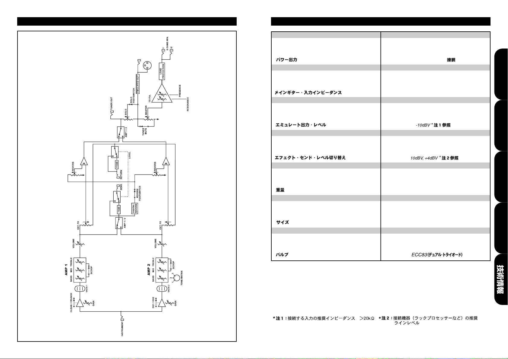
Block Diagram
67
Power Output 350W RMS into 8Ω
Potencia de salida 350W RMS sobre 8 Ω
Ausgangsleistung 350W RMS an 8 Ω
Puissance de sortie 350W RMS sous 8 Ohms
350W RMS / 8 Ω
Main Guitar • Input Impedance 1 MΩ
Impedancia de entrada principal de guitarra 1 MΩ
Guitar • Input Eingangsimpedanz 1 M Ω
Impédance d'entrée 1 M Ω
1 M Ω
Emulated Output • Level -10dBV * see Note 1
Nivel de salida de línea simulada -10dBV * ver nota 1
Emulated Output • Ausgangspegel -10dBV * siehe Hinweis 1
Niveau de sortie -10dBV voir note 1
FX Send • Level Switchable -10dBV, +4dBV * see Note 2
Nivel de envío FX -10dBV, +4dbV * ver nota 2
FX Send • Ausgangspegel -10dBV, +4dBV * siehe Hinweis 2
Niveau de sortie d'effet -10dBV, +4dBV * voir note 2
Weight 18kg
Peso 18kg
Gewicht 18kg
Poids 18kg
18kg
Size (mm) 746x310x215
Tamaño (mm) 746 x 310 x 215
Maße (mm) 746 x 310 x 215
Taille (mm) 746 x 310 x 215
746 x 310 x 215
Valves 2 x ECC83 (Dual Triode)
Válvulas 2 x ECC83 (Triodo doble)
Röhres 2 x ECC83 (Dual Triode)
Lampes 2 x ECC83 (double triode)
2 x
* Note 1: Recommended for connection to inputs
with input impedance >20K Ω
* Nota 1: Se recomienda conectar a entradas
con impedancia superior a 20KΩ
* Hinweis 1: Empfohlen für Inputs mit eine
Eingangsimpedanz >20K Ω
* Note 1: Recommandée pour une impédance
d'entrée supérieure à 20KΩ
* Note 2: Recommended for use with line level
equipment (i.e. rack processor etc.)
* Nota 2: Se recomienda utilizar con equipo con
nivel nominal de línea ( como procesadores de rack, etc...)
*
Hinweis 2: Empfohlen für die Benutzung mit
Equipment auf Linepegel (z.B.Studioeffektgeräte etc.)
* Note 2: Recommandée pour des niveaux de ligne
de type processeur d'effets en rack.
Technical
Técnicas
Technische
Techniques
Technical Specification

MODE FOUR FRONT PANEL FEATURES
1 3 5 7 8 10 12 13 14 15 16 18 20 22 2523 27 28
2 4 6 9 11 17 19 21 24 26
CONNECT SPEAKERS BEFORE USE
PLEASE REFER TO HANDBOOK
Made in England by:
Marshall Amplification plc,
Bletchley, Milton Keynes, England.
MAINS INPUT
120V ~ 60Hz
820 Watts
FOOTSWITCH FX RETURNTUNER OUT
FX SEND
FX LEVEL
LOAD
PROTECTION
ACTIVE
+4dBV
-10dBV
EMULATED LINE OUTPUT
WARNING!:
RISK OF HAZARDOUS ENERGY!
AVIS!:
ENERGIE ELECTRIQUE DANGEREUSE!
LOUDSPEAKERS
(Minimum Total Imp. 8Ω)
SPEAKER OUTPUTS
REFER TO TABLE
REFER TO
HANDBOOK
OUTPUT I II
235W 16 Ω X
350W X 8Ω
350W 16 Ω 16 Ω
III
WARNING:
DO NOT OBSTRUCT VENTILA
TION GRILLES
ATTENTION:
NE PAS OBSTRUER LES GRILLES DE VENTILATION
MODEL: MF350
OUTPUT: 350 Watts RMS into 8Ω
!
!
WARNING!:
SHOCK HAZARD. DO NOT OPEN. TO REDUCE THE RISK
OF FIRE OR ELECTRIC SHOCK DO NOT EXPOSE THIS EQUIPMENT TO RAIN OR
MOISTURE. THIS APPARATUS MUSTBE EARTHED.
AVIS!:
RISQUE DE CHOC ELECTRIQUE. NE PAS OUVRIR. POUR EVITER
LES RISQUES D’INCENDIE ET DE DECHARGES ELECTRIQUES, N’EXPOSEZ
JAMAIS CET APPAREIL A L’HUMIDITE OU ALA PLUIE. CONNECTER CET
APPAREILA LA TERRE.
CAUTION!:
TO REDUCE THE RISK OF ELECTRIC SHOCK DO NOT
REMOVE COVER. NO USER SERVICEABLE PARTS INSIDE. REFER SERVICING TO
QUALIFIED SERVICE PERSONNEL.
ATTENTION!:
POUR EVITER LES RISQUES DE DECHARGES
ELECTRIQUES, NE PAS OUVRIR LE COUVERCLE. CETAPPAREIL NE COMPORTE
AUCUNE PIECE SUSCEPTIBLE D’ETRE REPAREE PAR VOS SOINS. FAITES
TOUJOURS APPELA UN TECHNICIEN QUALIFIE POUR TOUTE REPARATION.
This device complies with Part 15 of the FCC Rules. Operation is subject to the
following two conditions: (1) this device may not cause harmful interference, and (2)
this device must accept any interference received, including interference that may
cause undesired operation.
This Class B digital apparatus complies with Canadian ICES-003.
Cet appareil numérique de la classe B est conforme à la norme NMB-003 du Canada.
1 2 3 4 5 6 7 8 9 10
MODE FOUR REAR PANEL FEATURES
70 71

Suggested Settings ●Configuraciones que sugerimos ●Soundvorschläge ●Exemples de réglages
●
Full Bodied Clean
'Plexi' Clean
Dynamic Blues Solo
Hotrodded JCM800
Extreme Thrash
Solid Rhythm
Classic Metal
Detuned
Extreme Detuned
Smooth Shred
AMP 1
OUT
OUT
IN
IN
OUT
OUT
IN
OUT
OUT
IN
72 73
AMP1
AMP2
 Loading...