

Marshall Amplification JVM2, JVM210H, JVM205H, JVM215C, JVM210C Owner's Manual
...

Contents
B
English
Welcome from Jim Marshall 1
Overview 2
The Basics 4
Channel Overview 5
Front Panel Operation 6
Rear Panel Operation 8
Technical Specification 10
Español
Bienvenida de Jim Marshall 11
Descripción General 12
Lo Básico 14
Descripción General del Canal 15
Panel Frontal 16
Panel Trasero 18
Especificaciones Técnicas 20
Deutsch
Ein Gruß von Jim Marshall 21
Übersicht 22
Die Basics 24
Kanal-Übersicht 25
Frontpanel Bedienung 26
Bedienelmente Auf Der Ruckseite 28
Technische Daten 30
Français
De la part de Jim Marshall 31
Présentation 32
Les Bases 34
Présentation du canal 35
Fonctionnement de la façade 36
Fonctionnement de la face arrière 38
Caractéristiques Techniques 40
Japanese
41
42
44
45
46
48
50

INTRODUCTION
Congratulations on the purchase of your all-valve ʻJVMʼ Series amplifier, which is
designed, engineered and constructed to the highest possible standards at the
Marshall factory in Bletchley, England. At Marshall we understand the necessity of
achieving the right tone and feel to help inspire you to reach your full creative
potential. Listening to what guitarists want, painstaking R&D and a commitment to
manufacturing excellence has made the Marshall legend. These values have remained
at the core of Marshallʼs identity, from 1962 to the present day, and will continue to do
so over the next half century and beyond.
Your ʻJVMʼ Series amplifier has been designed to produce a broad sonic palette,
making it an incredibly versatile tool, whether performing live on stage, recording or
rehearsing. It can take you from classic Marshall JTM45™/ Plexi™ clean and
overdriven tones to JCM800™ grunt and on to contemporary high gain insanity. Fully
programmable, the ʻJVMʼ Series has unprecedented tonal control, with three modes
per channel, independent Reverbs, Parallel/Series FX Loop and Stompware®
footswitching technology.
The ʻJVMʼ Series is truly a testament to the Marshall legacy of great guitar products
and we sincerely hope that your ʻJVMʼ amplifier proves indispensable, providing you
with years of legendary Marshall tone, whatever your playing situation.
ENGLISH
Thank you for choosing Marshall.
-The Marshall Team
1
3
ENGLISH
For example, you could program a mixture of
switching functions (in our example switches #1
and #2 work in Preset Store mode, and #3 plus
#4 work in Switch Store mode), so that:
Footswitch #1 = Overdrive channel, green mode
with Master Volume ʻ1ʼ, Reverb ʻonʼ and FX loop
ʻoffʼ.
Footswitch #2 = Clean channel, red mode with
Master Volume ʻ2ʼ, Reverb ʻoffʼ and FX loop on.
Footswitch #3 = FX loop on/off
Footswitch #4 = Master 1/2
All the settings are stored within your footswitch;
this means it can be plugged into any JVM
amplifier and all your footswitch settings can be
instantly recalled.
Details on how to program your footswitch can
be found later in this manual.
III. Power Amp
The power amp stage of the JVMs is based on
the same as the one found in the JCM800 2203
and 1959 Superlead amplifiers and their 50W
cousins, responsible for the legendary Marshall
roar it has been adjusted to suit the variety of
tones found in the JVM. This section features
Presence and Resonance control to help shape
the overall tone of your JVM amplifier.
Your JVM is also equipped with a Silent
Recording mode. When the STANDBY switch is
OFF the power amplifier section is disabled but
the rest of the amplifier remains fully
operational.
IV. Studio Quality Reverb
The Marshall JVM is equipped with a studio
quality digital reverb routed in parallel to the
main signal and mixed by means of a valve.
When the reverb is engaged no degradation of
the direct signal occurs and when off it is
effectively removed from the circuit. Each of the
JVMʼs channels also has its own dedicated
Reverb level control.
The Reverb switching has been designed to
avoid abrupt cut offs in the reverb tail so when
changing from channel to channel or switching
the reverb off, its tail naturally decays.
Overview
I. Channels, Modes & Memory
Presenting the 2-channel, 100W and 50W
all-valve JVM amplifiers. Their 2 channels boast
3 modes, giving you a total of 6 different modes
to choose from - each with its own unique gain
structure. Even though their front panel contains
a total of 16 control knobs and 6 LED switches,
the JVM is simple to understand and operate
thanks to its extremely logical front and rear
panel layouts.
ENGLISH
The front panel contains dedicated sets of
controls for each of their 2 channels CLEAN / CRUNCH and OVERDRIVE - plus
MASTER and REVERB sections. Each channel
contains the familiar controls, Volume, Bass,
Middle, Treble and Gain. The REVERB section
consists of 2 Reverb level controls, one for each
channel while the MASTER section is comprised
of 2 footswitchable Master Volumes, plus master
RESONANCE and PRESENCE controls that
work universally on both channels.
Each of the 2 channels has 3 switchable modes.
These are selected by the MODE switch
dedicated to each channel. To select a channel
press its respective MODE switch (or step on
the relevant button on the supplied 4-way
footswitch - see section II. Footswitch). To
scroll through the selected channel's 3 modes
keep pressing the said button and the colour of
the LED in the switch will change from green to
orange to red and then back to green. Doing this
steps-up the gain level each time (red being the
highest and green the lowest for each channel)
and changes the channel's tonal voicing to suit.
When you leave and then reselect a channel, it
will automatically recall the last active mode as
both channels remember the last mode they
were in until a change is made. For instance, if
you select the Overdrive channel's orange mode
and then go to the Clean channel, when you
reselect the Overdrive channel it will still be
orange.
In addition to channel and Mode selection, other
features switchable via the front panel and the
supplied 4-way footswitch are Reverb (on/off)
Master Volume selection (1 or 2), and
Series/Parallel effects loop (on/off). All 3 of
these options are also remembered by each
Mode.
To sum up, each of the JVMs 6 Modes will
remember its most recent Reverb, FX loop and
Master Volume selection. Additionally mode
setups can also be saved and recalled to one of
128 locations via MIDI.
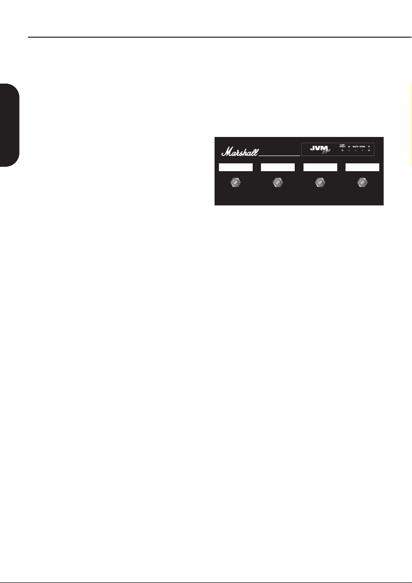
II. Footswitch (UK patent pending)
The JVM come supplied with a 4-way
programmable footswitch which can be
connected to the amp via any standard guitar
cable.
MODEL: PEDL-00045
4321
*Please note that the supplied Footswitch lead is
unscreened and not suitable for guitar.
The 4-button footswitch features 5 LEDS
marked CLEAN / CRUNCH, OD, MASTER,
REVERB & FX. The LEDs for each of the 2
channels are 3-coloured Green, Orange and
Red, visually telling you which channel and
mode is selected alongside the status of Master,
Reverb and FX loop.
The footswitch enables you to assign any of its
4 switches to instantly recall any front panel
function (Switch Store Mode) or complete
channel setup (Preset Store Mode) in any order
and combination.
For example, you could program it so that:
Switch Store Mode
Any footswitch is assigned to act as any one of
your ampʼs front panel switches:
Channel/Mode; Reverb on/off; Master Volume
1/2 and FX Loop on/off.
If a switch is assigned to select a particular
channel once is has been activated, it can be
used to scroll through the three modes, just like
its respective front panel switch.
Or…
Preset Store Mode
Each switch can be programmed to instantly call
up a combination of JVM button options to form
a Preset.
2

For example, you could program a mixture of
switching functions (in our example switches #1
and #2 work in Preset Store mode, and #3 plus
#4 work in Switch Store mode), so that:
Footswitch #1 = Overdrive channel, green mode
with Master Volume ʻ1ʼ, Reverb ʻonʼ and FX loop
ʻoffʼ.
Footswitch #2 = Clean channel, red mode with
Master Volume ʻ2ʼ, Reverb ʻoffʼ and FX loop on.
Footswitch #3 = FX loop on/off
Footswitch #4 = Master 1/2
All the settings are stored within your footswitch;
this means it can be plugged into any JVM
amplifier and all your footswitch settings can be
instantly recalled.
Details on how to program your footswitch can
be found later in this manual.
III. Power Amp
The power amp stage of the JVMs is based on
the same as the one found in the JCM800 2203
and 1959 Superlead amplifiers and their 50W
cousins, responsible for the legendary Marshall
roar it has been adjusted to suit the variety of
tones found in the JVM. This section features
Presence and Resonance control to help shape
the overall tone of your JVM amplifier.
ENGLISH
Your JVM is also equipped with a Silent
Recording mode. When the STANDBY switch is
OFF the power amplifier section is disabled but
the rest of the amplifier remains fully
operational.
IV. Studio Quality Reverb
The Marshall JVM is equipped with a studio
quality digital reverb routed in parallel to the
main signal and mixed by means of a valve.
When the reverb is engaged no degradation of
the direct signal occurs and when off it is
effectively removed from the circuit. Each of the
JVMʼs channels also has its own dedicated
Reverb level control.
The Reverb switching has been designed to
avoid abrupt cut offs in the reverb tail so when
changing from channel to channel or switching
the reverb off, its tail naturally decays.
3

The Basics
We recommend that you fold out the inside back
cover of this manual so that diagrams of the
ampʼs front and rear panels are visible while you
read.
MAINS INPUT & FUSE (17)
Your amp is provided with a detachable mains
(power) lead, which is connected here. The
specific mains input voltage rating that your
amplifier has been built for is indicated on the
rear panel.
ENGLISH
WARNING: Before going any further, make
sure your amplifier is compatible with your
electrical supply. If you have any doubt,
please get help from a qualified technician your Marshall dealer can help you in this
respect.
The correct value of mains fuse is specified on
the rear panel of the amplifier. NEVER attempt
to bypass the fuse or fit one of the incorrect
value.
Mains (POWER) Switch (1)
This is the On/Off switch for the mains electric
power to the amplifier.
Note: Please ensure the amplifier is switched off
and unplugged from the mains electricity supply
whenever it is moved!
INPUT Jack Socket (10)
You must always use a screened (shielded)
guitar cable and never use an unscreened
(unshielded) speaker cable. Also, this cable
should be one of good quality. If you are in any
doubt regarding this, your Marshall dealer will be
more than happy to help and advise you.
Getting Started & Powering Up
1. Make sure that the speakers/cabinet(s) are
connected to the correct impedance
LOUDSPEAKER jack(s) on the rear panel (11).
See page 8 for specifics regarding impedance
matching. If youʼre using an extension cabinet
make sure its rating is enough to handle the
power of the amp and also that youʼre using a
proper speaker cable. Never use a screened
(shielded) guitar cable for this purpose.
Marshall recommends you always leave a
(speaker) load attached to the unit.
2. Ensure that both MASTER VOLUMES on the
front panel (5) are set to zero.
3. Connect the Footswitch Cable to the
Footswitch and then connect to the
FOOTSWITCH Socket (15) on the rear panel of
the amplifier.
4. Connect the supplied mains (power) lead into
the MAINS INPUT (17) on the rear panel first
and then into an electrical outlet.
5. Plug your guitar into the INPUT jack socket
(10) on the front panel.
6. Turn the front panel POWER switch (1) on.
This will glow red then wait for a couple of
minutes.
7. After waiting a couple of minutes, engage the
STANDBY switch (2). Leaving the amp on
ʻStandbyʼ for a period allows the valves to come
up to their correct operating temperature. In
order to prolong valve life, the STANDBY switch
should also be used to turn the amplifier on and
off during breaks in a performance.
STANDBY Switch & Silent recording (2)
As stated above the STANDBY Switch is used in
conjunction with the POWER Switch to ʻwarm
upʼ the amplifier before use and to prolong the
life of the output valves.
When the amplifier is in standby mode the
whole preamplifier section continues running at
its nominal voltages whilst the power amplifier
remains in a standby status. This allows the
amplifier to be used for silent recording or
preamplification purposes.
NOTE : Only when the STANDBY is off can
the amplifier be used without a load for silent
recording. Always ensure a load is
connected when leaving the silent recording
mode, i.e. when switching the STANDBY
switch ON.
WARNING!
1. Failure to do any of the above will damage
your amp.
2. NEVER use your amp without a (speaker)
load attached when the Standby Switch is
ON.
4

Channel Overview
The JVMʼs front panel is divided into 2 main
sections: Channels and Master. Each of its
channels has 3 modes which are distinguished
by a different coloured light (green, orange or
red) appearing in the respective MODE switch;
the preamplifierʼs gain structure is uniquely
reconfigured for each and every mode.
CLEAN/CRUNCH CHANNEL (8)
CLEAN/CRUNCH GREEN MODE: This is the
cleanest of the three modes and, in keeping with
traditional clean amps, it uses a simple and
straightforward circuit keeping the signal as pure
as possible. In this Mode the channelʼs Volume
control is taken out of circuit as is the case in
vintage amplifiers of this nature. This is the only
JVM mode where this happens.
CLEAN/CRUNCH ORANGE MODE: This mode
shares the preamp topology of the classic
Marshall JTM45/1959 ʻPlexiʼ models (i.e.: gain +
gain + tone) but with a bit more gain than is
found in the originals.
CLEAN/CRUNCH RED MODE: This mode is
reminiscent of the Marshall JCM800 2203
amplifier, a staple of hard rock. The gain
structure is gain + gain + gain + tone.
OVERDRIVE CHANNEL (9)
OVERDRIVE GREEN MODE: This is very
similar to the hot-rodded JCM800 sound found
in ʻCrunch Redʼ, allowing you to dial-in two
distinctly different yet similar crunch sounds if
you so wish - one in each channel.
ENGLISH
OVERDRIVE ORANGE MODE: This adds
another gain stage to the ʻOverdrive Greenʼ
circuit, resulting in a sound thatʼs perfect for
singing leads and hard rock/heavy metal tones.
OVERDRIVE RED MODE: Adds more gain to
the ʻOverdrive Orangeʼ for a high gain Marshall
sound.
5

Front Panel Operation
Channel Section
Pressing a channel button has two functions:
When coming from a different channel it recalls
the last setting in the new selected channel.
When pressing in the same channel it cycles the
modes: GREEN > ORANGE > RED > GREEN...
Each mode remembers the FX, Reverb and
Master settings.
ENGLISH
Example: You are in OVERDRIVE ORANGE
with FX + REVERB and you press CLEAN. The
amp switches to the last Clean mode you had
(letʼs assume it was CLEAN GREEN with
REVERB). If you press the OVERDRIVE switch
you go back to OVERDRIVE ORANGE with FX
+ REVERB. This allows bouncing between
channels without losing the settings. If you now
press OVERDRIVE again, you go to
OVERDRIVE RED with whatever FX, MASTER
and REVERB settings you had last time you
were in this mode.
Pressing REVERB (7) switches the reverb ON
and OFF in the current channel.
Pressing FX LOOP (4) switches the parallel FX
loop ON and OFF in the current channel.
Master Section
REVERB Control (7)
Alongside the REVERB switch each channel
has its own reverb control allowing individual
level settings of the effect.
Presence and Resonance constitute a powerful
power amplifier equaliser, allowing responses
from a ʻ^ʼ shape when they are fully
counterclockwise, which is felt as a mid boost,
to a ʻvʼ shape when they are turned clockwise,
which is felt as a scooped sound. Again, the
effectiveness of these controls is highly
dependant on the kind of connected speakers.
Care has to be taken to avoid over excursion of
the speaker cones in high resonance settings.
FX LOOP (4)
This is a programmable FX loop which features
a MIX control on the rear panel and it is located
after the pre-amp, right before the reverb and
serial loop circuits. Pressing the FX Loop switch
(4) engages this effects loop. Please refer to the
Serial / Parallel Loop description later on in the
handbook for its operation.
FOOTSWITCH / MIDI PROGRAM (3)
This switch has a dual function:
Pressing it once we enter the FOOTSWITCH
PROGRAM mode. It is indicated by a
continuous red light.
Pressing it twice we enter the MIDI PROGRAM
mode. It is indicated by a blinking red light.
Footswitch program and use
The JVM range features a new type of fully
configurable footswitch. Connection to the
amplifier requires a standard mono 1/4" jack to
jack cable. Any guitar lead will work and
practically there should be no limit in its length.
MASTER 1 / MASTER 2 (5)
These are the master volume controls of the
amplifier. They can be assigned individually to
each of the modes as you wish and the master
selection will be stored in each of the modes.
PRESENCE, RESONANCE (6)
These controls are power amplifier controls and
only have effect when playing through a speaker
(not in silent recording). They affect how the
power amplifier reacts to the connected
speakers and how much control the amplifier
has over them.
Increasing the RESONANCE control
emphasises the natural speakerʼs resonance for
an improved bass response. In the same way,
increasing the PRESENCE control emphasises
the speakerʼs high frequencies which will be
heard as an improved high frequency response
which adds presence to the sound.
When the front panel FOOTSWITCH / MIDI
PROGRAM switch is off, the footswitch operates
in safe mode and executes the commands the
moment the switch is pressed down.
If you enter the FOOTSWITCH PROGRAM
mode (LED red) you will be able to program the
footswitch but nevertheless the footswitch and
the amplifier will remain fully operational with the
only difference that the commands will be
executed when releasing the footswitches, as
opposed to the normal mode.
Each of the individual footswitches has 2 modes
of operation: preset store and switch store.
In preset store mode, any of the footswitches
can be configured to store the current amplifier
status. The current channel, master, FX and
reverb status will be stored and recalled when
the respective footswitch is pressed.
6

To store the current status simply:
Set the amplifier to FOOTSWITCH PROGRAM
mode (red light ON).
Press and hold the desired switch for about 3
seconds.
The FX footswitch LED will flicker a couple of
times indicating that the preset has been stored.
In switch store mode, any of the footswitches
can be configured to replicate the front panel
switches and the amplifier will react exactly in
the same way as when you operate them on the
front panel.
MIDI operation
Pressing the FOOTSWITCH / MIDI PROGRAM
switch (3) twice puts the amplifier in MIDI
waiting mode, the LED will flash until a valid
MIDI program change command is received.
On reception of a MIDI program change
command the amplifier stores the current status
(Channel + FX + Reverb + Master Settings) in
the MIDI program number received. It is
possible to store up to 128 different MIDI
presets.
To exit this status without waiting for incoming
MIDI data press the FOOTSWITCH / MIDI
PROGRAM switch (3) again.
ENGLISH
All the front panel switches can be mapped to
any of the footswitches without any limitation.
The only exception is the FOOTSWITCH / MIDI
PROGRAM switch which cannot be assigned to
the footswitch.
To assign any of the front panel switches
(except FOOTSWITCH / MIDI PROGRAM) to
any of the footswitches simply:
Set the amplifier to FOOTSWITCH PROGRAM
mode (red light ON).
Press and hold the desired footswitch.
While holding the footswitch down, in less than
3 seconds, press the front panel switch you
want to map.
The FX footswitch LED will flicker a couple of
times indicating that the switch has been
mapped.
From now on the selected footswitch will act
exactly in the same way as if you press the
related front panel switch.
Switches and presets can be assigned as
wished without limitation and in any order
(again, except the FOOTSWITCH / MIDI
PROGRAM switch). The footswitch configuration
is stored in the footswitch itself, not in the
amplifier. Resetting the amplifier will not affect
the footswitch configuration as well.
Note about MIDI channels: By default the
amplifier is configured to listen to MIDI channel
#1 but it can be changed to listen to any of the
16 MIDI channels as follows:
Switch the amplifier off (Power switch (1), not
Standby (2)).
Press and hold the FOOTSWITCH / MIDI
PROGRAM switch (3).
Switch the amplifier on (Power switch (1)).
Release the FOOTSWITCH / MIDI PROGRAM
switch (3), the LED will start to flash.
Send ANY MIDI command using your MIDI
pedalboard or any other MIDI equipment.
The amplifier will detect which channel came in
and configure itself to listen to that MIDI channel
only. From now on any MIDI preset you had
previously stored will be activated only on the
new channel regardless of what channel you
used before, this allows a fast reconfiguration
should there be a MIDI conflict with any other
outboard equipment.
If you want to exit the MIDI channel selection
without any action press the
FOOTSWITCH / MIDI PROGRAM switch (3)
while waiting for MIDI data.
The footswitch can be hot-swapped and
synchronises itself with the amplifier after
connection. However it is recommended to
connect the footswitch lead to the footswitch
side first and then connect it to the amplifier.
7

Rear Panel Operation
SERIAL / PARALLEL FX LOOP (12)
The JVM is equipped with a series / parallel FX
loop. Connect your external FX equipment input
to the JVM SEND jack, and the FX output to the
JVM RETURN jack. As described previously,
this effects loop can be bypassed from the front
panel and the amount of effect can be dialed in
with the MIX control.
The +4dBu/-10dBV switch allows you to
configure the loop for its use with either
ENGLISH
professional equipment (+4dBu setting) or with
guitar level effects like effects pedals (-10dBV
setting).
When MIX is set to WET all the signal goes
through the external loop, adding more direct
(unprocessed) signal as you turn it towards
DRY. This allows you to mix any amount of the
external effect without loosing or degrading the
direct signal quality.
When mixing the WET and DRY signals the
external effects processorʼs output should be
configured to remove the direct (unprocessed)
signal or unpleasant phasing effects may occur
when mixing it again in the amplifier. If the
amplifier sounds thin after connecting an
external effect check that no direct signal is
being returned from the processorʼs output.
Note that if the FX loop is ON and the MIX
control is set to WET without an external
processor connected, the amplifier will be
muted.
POWER AMP INSERT / SERIAL LOOP (13)
This is a passive loop connected right before the
master controls. It is a line level loop so it is
recommended to only use high headroom
devices to avoid signal degradation. Plugging
only into the return jack allows the use of the
JVMʼs power section overriding the preamp.
Master controls and the emulated line out are
located after the serial loop so it is still possible
to take advantage of those features when using
an external preamplifier. The loop can be taken
off the circuit by pressing the BYPASS switch,
but as opposed to the Series / Parallel loop this
switch cannot be programmed.
EMULATED LINE OUT (14)
The pre master volume signal, processed
through a 4x12 speaker cabinet emulator and
electronically balanced is made available at this
connector.
FOOTSWITCH (15)
Connect the supplied footswitch using any
standard 1/4" jack mono lead. Using any other
type of footswitch rather than the supplied will
have no effect and will be ignored by the
amplifier.
MIDI In / Through (16)
Connect any external MIDI equipment to the
MIDI In DIN socket. A copy of the signal in this
connector will be available on the MIDI thru
socket to allow daisy chaining of MIDI
equipment. Note that the JVM only accepts
incoming data and it is not able to send any
MIDI commands.
SPEAKER Outputs (11)
There are 5 speaker outputs available on the
rear panel. They are labelled according to the
intended impedances:
16 Ohm: connect any 16 Ohms guitar cabinet to
this jack.
8 Ohm: connect a single 8 Ohms guitar cabinet
or two 16 Ohms guitar cabinets.
4 Ohm: connect a single 4 Ohms guitar cabinet
or two 8 Ohms guitar cabinets.
WARNING: Although the JVM amplifier has 5
speaker outputs, never attempt to connect more
speakers than rated. The safe combinations are
1x16 Ohm, 1x8 Ohm, 1x4 Ohm, 2x16 Ohm or
2x8 Ohm. Any other speaker configuration may
stress the power amplifier section and in
extreme cases may lead to valve and/or output
transformer failure.
HINTS & TIPS
Factory Reset
This will erase all the MIDI presets and set MIDI
reception channel to #1. Please note that once
the memory is erased it cannot be recovered.
Switch the amplifier off (power switch off, not
standby switch).
Press and hold CLEAN/CRUNCH CHANNEL
switch.
Switch the amplifier on (power switch on, not
standby switch).
The 2 channel LEDs will glow red.
Release the switch.
8

To confirm the factory reset press OVERDRIVE
MODE switch.
If you want to abort, press any other switch.
Footswitch Reset:
It is possible to reset the footswitch to the
factory default status. This is achieved as
follows:
Unplug the footswitch at any of the cable sides.
Press and hold the switch #4 (right switch).
Plug in the footswitch cord.
Release the switch and the FX led will start
blinking.
If you want to erase the footswitch memory
press the switch #3. To keep the memory press
either the #1 or #2 switch. Please note that once
the memory is erased it cannot be recovered.
Release the switch and the footswitch will
synchronise with the amplifier.
The factory default is as follows:
FSW #1: Clean/Crunch Mode
FSW #2: Overdrive Mode
FSW #3: Master
FSW #4: Reverb
Hints
Hint 1: It is possible to use different modes in
the same channel with different volumes to
avoid imbalance between mode levels. To do
this simply create 2 presets in the footswitch
assigning MASTER 1 or MASTER 2 to any of
the modes.
Hint 2: To have a tuner output muting the
amplifier, connect the tuner to the FX send and
select the Clean channel. Turn the MIX control
to WET and switch the FX loop on. Store this
preset as described before and label it for
example as ʻtunerʼ. Obviously in this
configuration it is not possible to connect any
other effect to the loop.
Hint 3: To use a different preamplifier and
combine it with the JVM channels, connect the
external preamplifier output to the parallel loop
return and turn the MIX to WET. Connect the
external preamp input with a splitter to the
amplifiers input (it might be necessary to use an
active splitter to keep a high impedance and/or
an isolated one to avoid ground loops).
Switching the effects loop ON and OFF will
alternate between the external preamp and the
JVM preamp.
As the JVM reverb circuitry is connected after
the parallel loop it is also possible to create a
preset to add reverb to the external preamp. To
do this, simply switch the reverb ON and create
a preset in any channel with the reverb ON and
FX ON and assign it to the footswitch. That
would be external preamp + reverb.
You can also go further and assign a different
Master level to both external and internal
preamplifiers in the same way as you assigned
reverb.
Hint 4: Notes about using 2 heads
simultaneously. The suggested procedure is
connect the ʻmasterʼ head PREAMP OUT to the
ʻslaveʼ head POWER AMP IN and switch the
POWER AMP INSERT to ACTIVE in the ʻslaveʼ
amplifier.
ENGLISH
If you do not connect any effect to the
SERIAL / PARALLEL FX LOOP the MIX control
can be used to act like an extra volume control
in any of the channels.
In order to track the master volume settings in
both heads (as the master volume circuitry is
wired after the loop) it is suggested to use MIDI
control with both amplifiers programmed in the
same way. Connect the MIDI IN of one of the
amplifiers to the MIDI THROUGH of the other
and the pedalboard or MIDI equipment to the
remaining MIDI IN.
9

Technical Specification - Heads
JVM210H Head JVM205H Head
Power (RMS) 100W 50W
Valves 5x ECC83 + 4x EL34 5x ECC83 + 2x EL34
Main Guitar - Input Impedance 470kΩ 470kΩ
Emulated Output - Level +4dBu +4dBu
FX Send Level - selectable -10dBV, +4dBu -10dBV, +4dBu
Weight 22kg 17.5kg
Size (mm) W, H, D 750 x 310 x 215 750 x 310 x 215
ENGLISH
Technical Specification - Combos
JVM210C Combo JVM205C Combo JVM215C Combo
Power (RMS) 100W 50W 50W
Valves 5x ECC83 + 4x EL34 5x ECC83 + 2x EL34 5x ECC83 + 2x EL34
Main Guitar - Input Impedance 470kΩ 470kΩ 470kΩ
Emulated Output - Level +4dBu +4dBu +4dBu
FX Send Level - selectable -10dBV, +4dBu -10dBV, +4dBu -10dBV, +4dBu
Speaker(s) 1x Vintage + 1x Heritage 1x Vintage + 1x Heritage G12B
Weight 34.5kg 29.5kg 26.5kg
Size (mm) W, H, D 690 x 510 x 265 690 x 510 x 265 605 x 510 x 265
* EUROPE ONLY - Note:
This equipment has been tested and found to comply with the
requirements of the EMC Directive (Environments E1, E2 and E3 EN 55103-1/2) and the Low Voltage
Directive in the E.U.
* EUROPE ONLY - Note:
The Peak Inrush current for the JVM210H and JVM210C is 52 amps.
The Peak Inrush current for the JVM205H, JVM205C & JVM215C is 26 amps.
Note:
This equipment has been tested and found to comply with the limits for a Class B digital device,
pursuant to part 15 of the FCC rules. These limits are designed to provide reasonable protection against
harmful interference in a residential installation. This equipment generates, uses and can radiate radio
frequency energy and, if not installed and used in accordance with the instructions, may cause harmful
interference to radio communications. However, there is no guarantee that interference will not occur in a
particular installation. If this equipment does cause harmful interference to radio or television reception,
which can be determined by turning the equipment off and on, the user is encouraged to try to correct the
interference by one or more of the following measures:
Reorient or relocate the receiving antenna.
Increase the separation between the equipment and the receiver.
Connect the equipment into an outlet on a circuit different from that to which the receiver is connected.
Consult the dealer or an experienced radio/TV technician for help.
Follow all instructions and heed all warnings
KEEP THESE INSTRUCTIONS !
10

INTRODUCCIÓN
Felicidades por comprar un amplificador todo a válvulas de la serie "JVM" concebido,
diseñado y fabricado para cumplir las normas más exigentes de la fábrica de Marshall
en Bletchley, Inglaterra. En Marshall entendemos la importancia de lograr el sonido
correcto y las sensaciones que te ayuden a inspirarte para que saques todo tu
potencial creativo. Escuchar lo que quieren los guitarristas, el I+D y un compromiso
con la excelencia de fabricación han forjado la leyenda de Marshall. Estos valores son
la esencia de Marshall Amplification; siempre lo han sido y siempre lo serán, desde el
primer amplificador Marshall fabricado en 1962 hasta la serie actual "JVM" y las que
vendrán.
Tu amplificador de la serie "JVM" se ha diseñado para producir una amplia paleta
sonora, por lo que obtendrás una herramienta increíblemente versátil para las
actuaciones en directo, el estudio de grabación o los ensayos. Puede llevarte desde
los sonidos limpios y saturados del clásico Marshall JTM45™/ Plexi™ hasta el gruñido
del JCM800™ pasando por la locura de alta ganancia contemporánea. Totalmente
programable, la serie "JVM" tiene un control sonoro sin precedentes, con tres modos
por canal, reverbs independientes, bucle de efectos paralelos/serie y tecnología de
pedal Stompware®.
La serie "JVM" es realmente el testamento del legado de Marshall de fantásticos
productos para guitarras. Sinceramente esperamos que tu amplificador "JVM" te
resulte indispensable y que te ofrezca años del legendario sonido de Marshall
independientemente de tus necesidades.
Gracias por elegir Marshall.
-El Equipo de Marshall
ESPAÑOL
11
Descripción General
1. Canales, Modos y Memoria
Os presentamos el amplificador JVM totalmente a
válvulas de 100 y 50 W y 2 canales. Sus 2 canales
disponen de 3 modos, proporcionándote un total de
6 modos diferentes para elegir - cada uno con su
propia estructura de ganancia. Aunque su panel
frontal contiene un total de 16 controles y 6
interruptores con LED, el manejo del JVM es muy
sencillo gracias a la disposición y distribución lógica
de su panel frontal y trasero.
El panel frontal contiene controles exclusivos para
cada unos de sus 2 canales - CLEAN / CRUNCH y
OVERDRIVE - así como para la sección de
MASTER y la sección de REVERB. Cada canal
dispone de los ya conocidos controles de Volumen,
Graves, Medios, Agudos y Ganancia. La sección
de REVERB dispone de 2 controles de nivel de
Reverb, uno para cada canal, mientras que la
sección de MASTER está compuesta por 2
Volúmenes Master conmutables por pedal, más
unos controles de RESONANCIA y PRESENCIA
ESPAÑOL
que funcionan universalmente en ambos canales..
Cada uno de los 2 canales dispone de 3 modos
conmutables. Se seleccionan a través del
interruptor MODE de cada canal. Para seleccionar
un determinado canal, presiona su respectivo
interruptor MODE (o pisa en el interruptor que
corresponda de la pedalera de control de 4
pulsadores que se suministra - lee la sección II.
Pedalera de Control). Para ir desplazándote por los
3 modos del canal seleccionado mantén apretado
el mencionado botón y el color del LED en el
interruptor cambiará de verde a naranja, a rojo y de
vuelta al verde. Haciendo esto elevas el nivel de
ganancia cada vez (el rojo es el de más ganancia y
el verde el de menos) y cambias el timbre del
canal.
Cuando te vas de un canal y luego vuelves a él,
automáticamente se activará el último modo activo,
ya que ambos canales recuerdan siempre el último
modo en el que se encontraban antes de cambiar.
Por ejemplo, si seleccionas el modo naranja del
canal Overdrive y cambias al canal Clean, cuando
vuelvas al canal Overdrive, éste seguirá en el
modo naranja.
Además de la selección de modos y canales, hay
otras funciones que pueden ser conmutadas a
través del panel frontal o a través de la pedalera de
control de 4 interruptores, como la Reverb (on/off),
la selección Master Volumen (1 ó 2) y el lazo de
efectos en Serie/Paralelo (on/off). Cualquiera de
estas 3 opciones es también recordada por cada
modo.
Resumiendo, cada uno de los 6 modos del JVM
recordará la selección más reciente de Reverb,
Lazo de FX y Volumen Master. Adicionalmente, los
ajustes de los modos pueden ser grabados en una
de las 128 localizaciones vía MIDI.
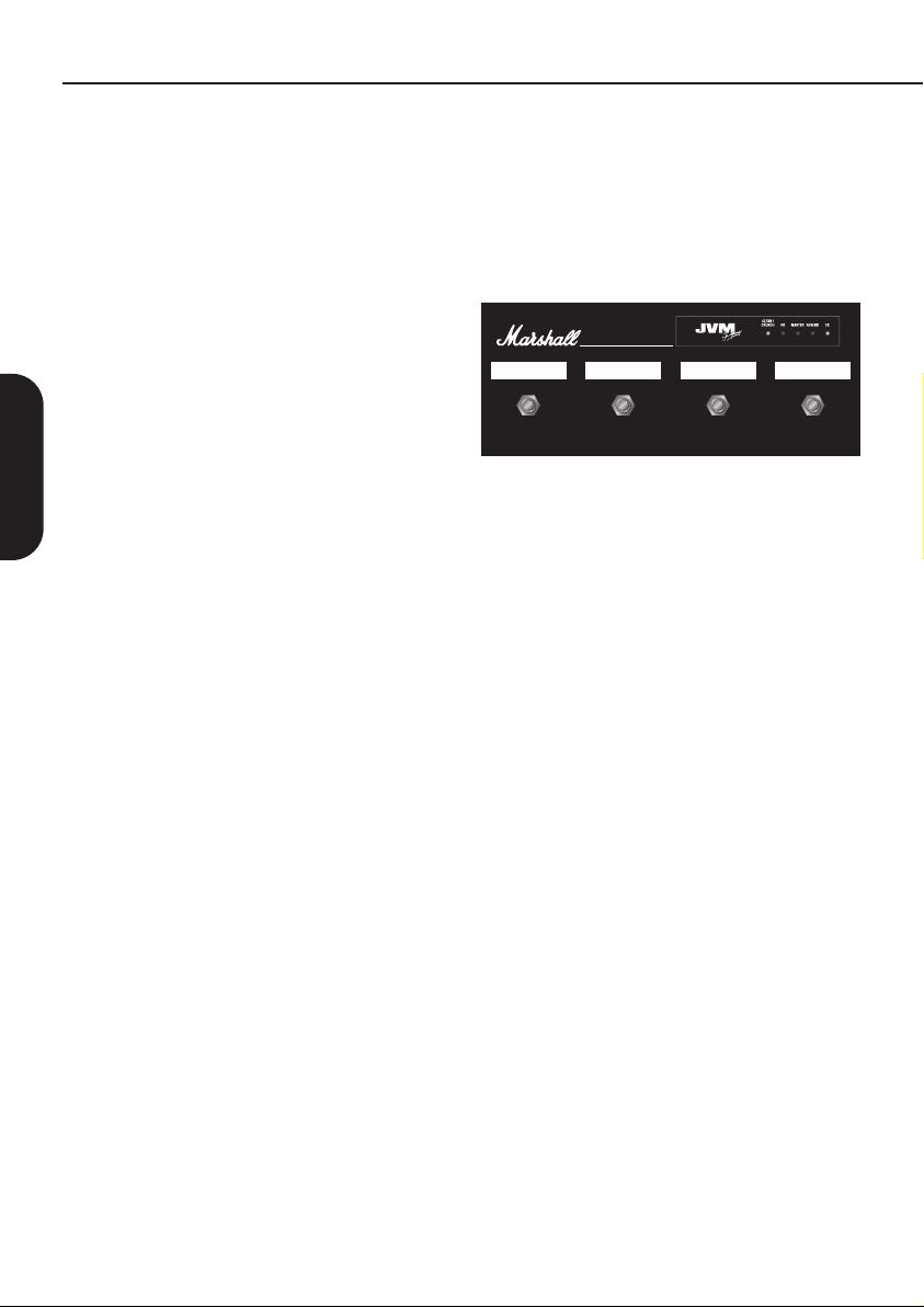
II. Pedal Controlador (Patente UK pendiente)
El JVM se suministra con una pedalera de control
programable de 4 interruptores, que se conecta al
amplificador con cualquier cable de guitarra
convencional.
MODEL: PEDL-00045
4321
*Por favor, toma nota que el cable de la pedalera
que se proporciona no está apantallado, y por
tanto, no es adecuado para enchufar la guitarra.
El pedal controlador de 4 pulsadores incorpora 5
leds marcados como CLEAN / CRUNCH / OD,
MASTER, REVERB y FX. Los leds para cada uno
de los dos canales son de tres colores: verde,
naranja y rojo y visualmente te van indicando qué
canal y qué modo está operativo, además del
estatus del Master, la Reverb y el Lazo de FX.
El pedal controlador te permite asignar cualquiera
de los 4 interruptores a cualquier función del panel
frontal (Switch Store Mode) o los cambios de canal
(Preset Store Mode), en cualquier orden y
combinación.
Por ejemplo, podrías programarlo de tal forma que:
Switch Store Mode (Modo de Almacenamiento
de los Interruptores)
Cualquier interruptor de la pedalera de control
puede activar cualquier interruptor del panel frontal:
Canal/Modo, Reverb on/off. Volumen Master 1 / 2
y Lazo de Efectos on/off.
Si un interruptor se asigna para seleccionar un
canal en particular, una vez que se ha activado,
puede usarse para desplazarse por los tres modos,
de la misma manera que lo harías con el interruptor
del panel frontal.
O…
Preset Store Mode (Modo de Almacenamiento
de Presets)
Cada interruptor puede ser programado para
activar al instante cualquier combinación de las
opciones que te ofrecen los botones del JVM para
formar un preset.
12

Por ejemplo, podrías programar una mezcla de
combinaciones de funciones (en nuestro ejemplo el
interruptor nº 1 y el nº 2 activan un modo de
almacenamiento de presets y el interruptor nº 3 y el
nº 4 activan el modo de almacenamiento de
interruptores), de modo que:
Interruptor de la Pedalera de Control nº 1 = canal
Overdrive, modo green con el Volumen Master ʻ1ʼ,
la Reverb ʻonʼ y el Lazo de Efectos ʻoffʼ.
Interruptor de la Pedalera de Control nº 2 = canal
Clean, modo red, Master volumen ʻ2ʼ, Reverb ʻoffʼ y
el Lazo de Efectos ʻonʼ.
Interruptor de la Pedalera de Control nº 3 = Lazo
de Efectos on/off.
Interruptor de la Pedalera de Control nº 4 = Master
volumen 1/2.
Todos los ajuste son grabados en la pedalera de
control; esto quiere decir que puedes conectarla en
cualquier otro amplificador JVM y que todos los
ajustes creados en la pedalera los mantendrás.
Los detalles de programación de la pedalera de
control los encontraremos más adelante en este
manual.
III. Etapa de Potencia
La etapa de potencia del JVM de 100 W está
basada en la misma que encontramos en los
amplificadores JCM800 2203 y 1959 Superlead,
así como en sus primos -hermanos de 50W,
responsables del legendario rugido Marshall, y ha
sido ajustada para acomodarse a la variedad de
tonos que podemos encontrar en el JVM. Esta
sección incorpora controles de Presencia y
Resonancia que te ayudarán a moldear el tono de
tu amplificador JVM.
Tu JVM está equipado también con un modo de
grabación silenciosa. Cuando el interruptor
STANDBY está apagado, la sección de potencia se
desconecta pero el resto del amplificador
permanece totalmente operativo.
IV. Reverb con calidad de Estudio
El Marshall JVM está equipado con una reverb
digital con calidad de estudio conectada en paralelo
con la señal principal y mezclada por medio de una
válvula. Cuando la reverb se activa no hay ninguna
degradación de la señal directa y cuando la reverb
se apaga se elimina del circuito de una forma
efectiva. Cada uno de los cuatro canales tiene su
propio control de nivel de Reverb.
La conmutación de la Reverb ha sido diseñada
para evitar el corte radical de la cola de la reverb,
así que cuando cambiemos de canal o
conmutemos la Reverb, su cola “morirá”
naturalmente.
ESPAÑOL
13

Lo Básico
Te recomendamos que despliegues la
contraportada de este manual para que los dibujos
y diagramas de los paneles frontal y trasero estén
visibles mientras lees el manual.
ENTRADA DE RED Y FUSIBLE (17)
Tu amplificador se suministra con un cable de red
que se conecta aquí. El voltaje específico de la
entrada de red se especifica en el panel trasero.
ADVERTENCIA: Antes de conectarte por
primera vez, asegúrate de que el amplificador
es compatible con la tensión de red local. Si
tienes alguna duda, dirígete a algún técnico
cualificado. Tu distribuidor Marshall te puede
orientar en este aspecto.
El valor correcto del fusible de corriente está
especificado en el panel trasero del amplificador.
Este cajetín tiene espacio para un fusible de
repuesto. NUNCA hagas 'puente' en el fusible o
pongas uno de valor incorrecto.
ESPAÑOL
Interruptor de Encendido (1)
Este es el interruptor (encendido/apagado) de
corriente del amplificador.
Nota: Asegúrate que el amplificador esté apagado
y desenchufado de la red cuando lo tengas que
mover.
Conector Jack de Entrada (10)
Debes utilizar siempre un cable de guitarra
apantallado. Nunca utilices un cable de bafle sin
apantallar. Además, este cable debe ser de buena
calidad. Si tienes dudas a este respecto, tu
distribuidor Marshall estará encantado de ayudarte
y aconsejarte.
Los Primeros Pasos Previos
1. Asegúrate que el bafle(s) esté conectado a los
jacks de BAFLE (LOUSDPEAKER) de la
impedancia correcta, situados en el panel trasero
(11). Mira en la página 18 para ver las
especificaciones respecto al ajuste de impedancias.
Si utilizas un bafle de extensión asegúrate que
tenga potencia suficiente para soportar un
amplificador de 100W y también que estés usando
un cable de altavoz apropiado. Nunca utilices
cables apantallados de guitarra para este fin.
¡ADVERTENCIA!
1. Si no haces caso de las advertencias
mencionadas arriba provocarás daños en tu
amplificador.
2. NUNCA utilices tu amplificador sin carga de
altavoz cuando actives el interruptor STANDBY.
Marshall recomienda que siempre dejes un bafle
conectado. (Por si acaso…)
2. Asegúrate que ambos VOLÚMENES MASTER
del panel frontal (5) estén situados en su posición
mínima (cero).
3. Conecta el cable de la pedalera de control a la
pedalera y a la entrada de la pedalera
FOOTSWITCH (15) del panel trasero del
amplificador.
4. Conecta el cable de red suministrado en la
entrada de red del panel trasero en primer lugar (17).
Luego conéctalo al enchufe de la red eléctrica.
5. Conecta la guitarra en el jack de entrada del
panel frontal (10).
6. Enciende el interruptor de encendido (1). Se
pondrá de color rojo. Espera un par de minutos.
7. Después de esperar un par de minutos, activa el
interruptor STANDBY (2). Al dejar el amplificador en
STANDBY durante un período de tiempo permites
que las válvulas empiecen a funcionar a la
temperatura adecuada. Para prolongar la vida de
las válvulas, el interruptor Standby se debe usar
para apagar el amplificador durante los descansos
de una actuación.
Interruptor de STANDBY y Grabación en
Silencio (2)
Como hemos mencionado arriba, este interruptor
se usa en conjunción con el de alimentación
principal para poder “calentar” el ampli antes de su
uso y prolongar la vida útil de las válvulas.
Cuando el amplificador está en modo Standby toda
la sección de previo continúa operativa mientras
que la sección de potencia permanece en standby.
Esto permite que puedas utilizar el amplificador
para aplicaciones de grabación en silencio.
Únicamente cuando el interruptor STANDBY
está desactivado podemos utilizar el
amplificador sin carga. Asegúrate siempre de
conectar una carga cuando acabes con el
modo de grabación en silencio y actives de
nuevo el interruptor STANDBY.
14

Descripción General del Canal
El Panel Frontal del JVM está dividido en dos
secciones principales: Canales y Master. Cada uno
de los canales dispone de 3 modos que se
distinguen por tener una luz de color diferente
(verde, naranja o rojo) que aparecen en su
respectivo interruptor MODE; la estructura de
ganancia del preamplificador se configura
particularmente para cada modo.
CANAL LIMPIO/CRUNCH (8)
MODO VERDE DEL CANAL LIMPIO/CRUNCH:
Este modo es el más limpio de los tres modos,
siguiendo con los amplis limpios tradicionales,
utiliza un circuito simple y mantiene la pureza de la
señal. En este modo el control de volumen del
canal está quitado del circuito, como pasa en los
amplificadores vintage de esta naturaleza. Este es
el único modo del JVM donde pasa esto.
MODO NARANJA DEL CANAL
LIMPIO/CRUNCH: Este modo comparte la
estructura de previo de los modelos clásicos de
Marshall, los Plexi JTM45/1959
(ganancia+ganancia+tono), pero con un poco más
de ganancia que sus predecesores
MODO ROJO DEL CANAL LIMPIO/CRUNCH:
Este modo es una reminiscencia del modelo de
Marshall JCM800 2203, un icono del Hard Rock.
La estructura de ganancia es: ganancia + ganancia
+ganancia +tono.
CANAL OVERDRIVE (9)
MODO VERDE DEL CANAL OVERDRIVE: Este
modo es muy similar al sonido de un JCM800 que
encontramos en el modo rojo del canal Crunch,
permitiéndote así tener dos sonidos muy parecidos,
uno en cada canal.
MODO NARANJA DEL CANAL OVERDRIVE: En
este modo se añade otra etapa de ganancia al
circuito del modo verde, dando como resultado un
sonido muy apropiado para solos y tonos “Heavy
Metal y Rock duro”.
MODO ROJO DEL CANAL OVERDRIVE: Añade
más ganancia al modo Naranja del canal
OVERDRIVE para sonidos Marshall de alta
ganancia.
ESPAÑOL
15

Panel Frontal
Sección de Canal
Apretar un botón de canal tiene dos funciones:
Cuando vienes de otro canal, se activará el nuevo
canal con el último ajuste.
Cuando presionas el mismo canal se activa el ciclo
de los Modos: VERDE > NARANJA > ROJO >
VERDE…
Cada modo recuerda los ajustes efectuados en el
FX, la Reverb y el Volumen Master.
Por ejemplo: Estás situado en el modo NARANJA
del CANAL OVERDRIVE con FX + REVERB,
entonces presionas el botón CLEAN. El ampli
conmuta el último modo Clean que tenías.
(Supongamos que era el modo VERDE del canal
CLEAN con REVERB). Si presionas el botón
OVERDRIVE vuelves al modo NARANJA del
Canal OVERDRIVE con FX + REVERB. Esto te
permite ir alternando entre lo canales sin perder los
ESPAÑOL
ajustes de los mismos. Si presionas OVERDRIVE
de nuevo, entonces te irás al modo ROJO del
canal OVERDRIVE con los ajustes de FX, Reverb
y Volumen Master que tuvieras en dicho modo.
Si presionas el botón de REVERB (7), activas o
desactivas la Reverb en el canal donde estés
situado.
Si presionas el botón FX LOOP (4) (Lazo de
Efectos), activas o desactivas el Lazo de Efectos
en paralelo en el canal donde estés situado.
Sección de Master
Control de REVERB (7)
Junto con el interruptor de Reverb de cada canal
se encuentra su propio control de reverb,
permitiéndote ajustes individuales de nivel del
efecto de reverb.
MASTER 1 / MASTER 2 (5)
Estos son los controles de volumen master del
amplificador. Pueden ser asignados
individualmente a cada uno de los modos y su
selección quedará grabada en cada uno de los
modos.
PRESENCIA / RESONANCIA (6)
Estos controles son específicos de la etapa de
potencia, por lo que únicamente estarán operativos
cuando toques a través de un bafle (no en
grabación silenciosa). Estos controles influyen en
cómo la etapa de potencia reacciona frente a los
altavoces y de cuánto control tiene el amplificador
sobre ellos.
Incrementando el control de RESONANCIA se
enfatiza la resonancia natural de los altavoces ante
una respuesta mejorada de graves. De la misma
forma, si incrementas el control de PRESENCIA se
enfatizará las frecuencias altas del altavoz lo que
redundará en una mejora de la respuesta de esas
frecuencias, lo que añade presencia al sonido.
La Presencia y la Resonancia constituyen un
ecualizador muy potente de la etapa de potencia,
permitiendo respuestas que van desde una curva
ʻ^ʼ cuando tenemos los controles al mínimo, lo que
nos sonará como un realce de medios, a curvas
tipo ʻvʼ cuando subimos estos controles, lo que nos
sonará como un sonido hueco. De nuevo, la
efectividad de estos controles dependerá en gran
medida del tipo de altavoces que tengamos
conectados. Hay que tener cuidado y evitar forzar
los conos de los altavoces cuando ajustemos el
control de Resonancia con valores altos.
LAZO DE EFECTOS (FX-LOOP) (4)
Este es un lazo de efectos programable que
incorpora un control de MEZCLA (MIX) en el panel
trasero y está localizado después del previo, justo
antes de los circuitos de la reverb y del lazo en
serie. Presionando el interruptor FX se activa el
Lazo de Efectos- Por favor, remitirse a la
descripción del Lazo Serie/ Paralelo que hay más
adelante en el manual para conocer su manejo.
PEDAL CONTROLADOR / PROGRAMA MIDI (3)
Este interruptor tiene una función dual:
Presionándolo una vez nos metemos en el modo
PROGRAM FOOTSWITCH (Pedal Controlador de
Programas). Nos lo indica una luz roja fija.
Presionándolo dos veces nos metemos en el modo
MIDI PROGRAM (Programas MIDI). Nos lo indica
una luz roja intermitente.
Programas del Pedal Controlador y su uso
La gama JVM incorpora una nueva pedalera de
control totalmente configurable. La conexión al
amplificador requiere de un cable convencional
mono jack - jack de 1/4". Puedes utilizar cualquier
cable de guitarra y de cualquier longitud.
Cuando el interruptor del panel frontal
FOOTSWITCH / MIDI PROGRAM está apagado,
la pedalera opera en modo seguro y ejecuta los
comandos en el momento que presionamos el
interruptor.
Si activas el modo FOOTSWITCH PROGRAM (led
rojo) podrás programar la pedalera, pero sin
embargo, la pedalera y el amplificador
permanecerán totalmente operativos con la única
diferencia que los comandos se ejecutarán, cuando
soltemos los interruptores, justo al contrario del
modo normal.
Cada uno de los interruptores de la pedalera tiene
16
 Loading...