

Page 1

U
S E R
M
A N U A L
Page 2

1
From Jim Marshall
I would like to thank you personally for selecting the
JFX-1 Digital Signal Processor.
As a result of the success of the internationally
acclaimed JMP-1 stereo valve MIDI pre-amp our first
digital product, my design team’s next step was to create
a Digital Signal Processor in the same style to expand the
guitarist’s range of usable sounds even further.
The same team who designed the JMP-1 devoted
many hours of research and development to the creation
of the JFX-1, the first Marshall Digital Signal Processor.
As with all products that bear the Marshall logo, no
matter how technically advanced, you can be sure that
the utmost care and highest possible standards of quality
control have been employed in the manufacture of your
JFX-1.
Though designed to be totally user friendly and
extremely intuitive to operate, I strongly suggest that you
read this manual carefully to fully understand and make
the most of the JFX-1’s many features.
I wish you many happy hours exploring the vast
range of sonic possibilities opened up by the processing
power of your new JFX-1.
Yours Sincerely,
From Jim Marshall
Warning List and Introduction
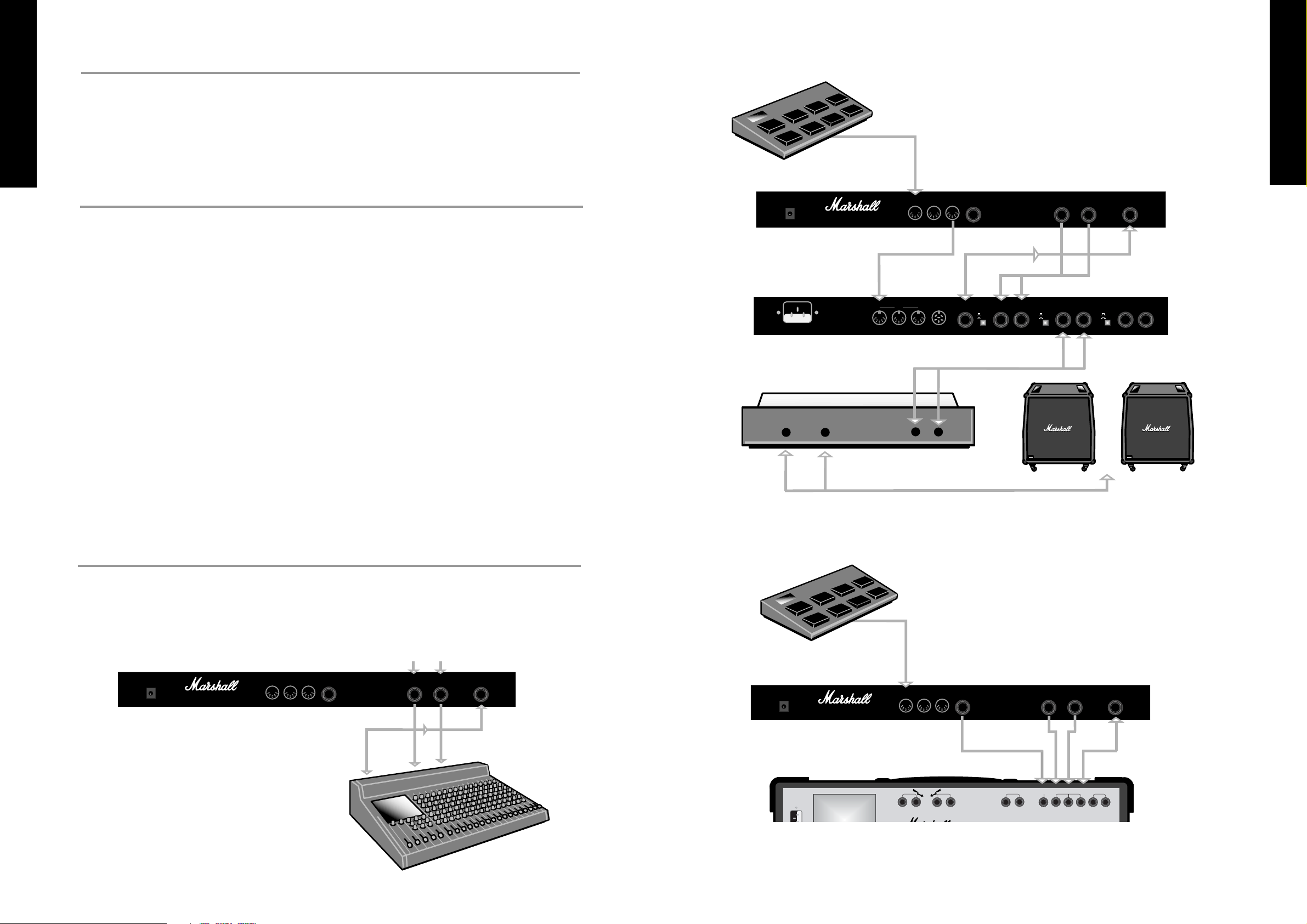
Section 1 - Connection Diagrams
A. With a Home / Recording Mixer
B. Stereo Rack System
C. With a Stereo or Mono Combo / Amp
Section 2 - Quick Reference Guide
2.1 - Selecting a Stored Pre-Set
2.2 - Editing Pre-Set Programs
2.3 - Storing Altered Parameter Values
2.4 - Naming a Program
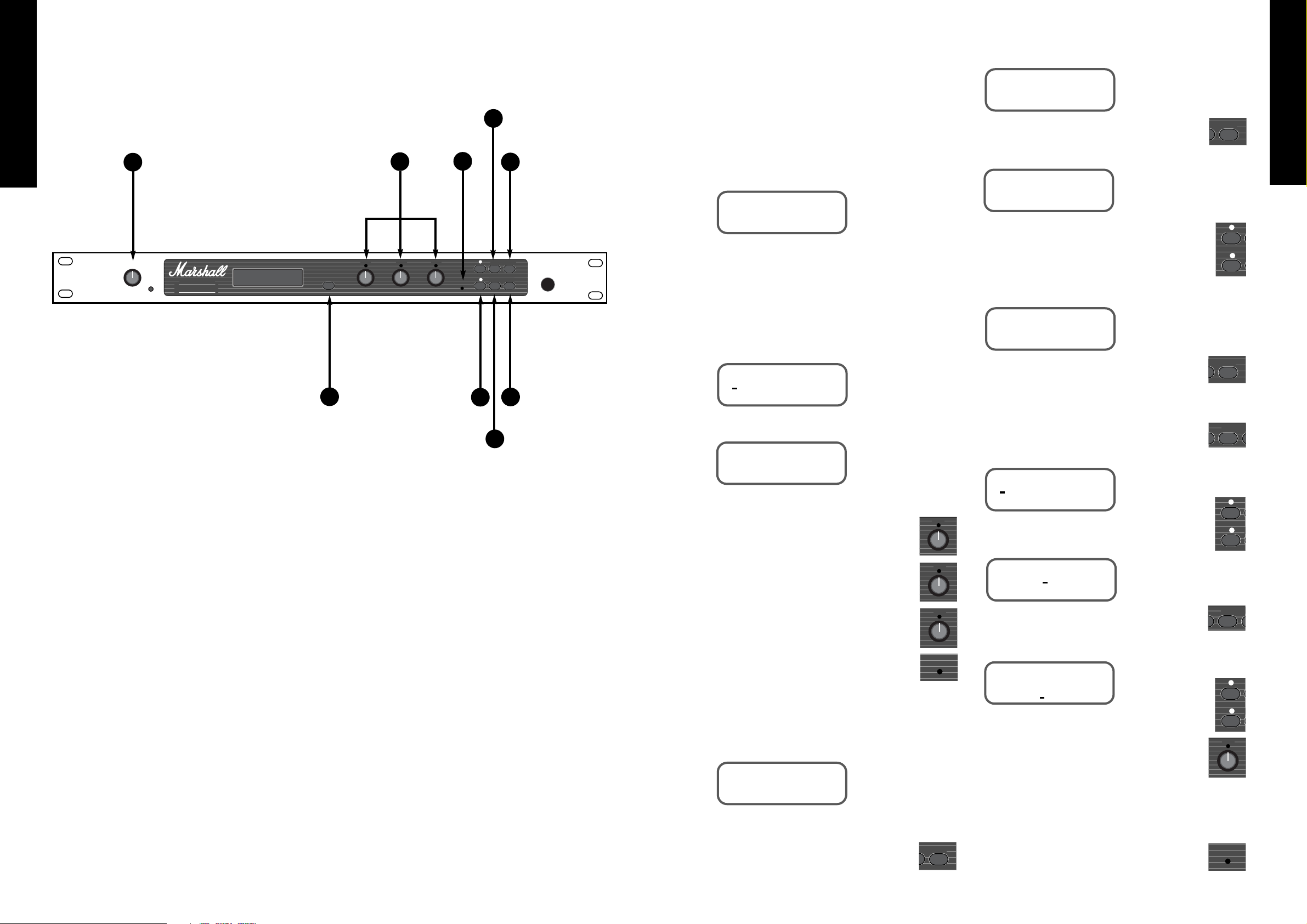
Section 3 - Front Panel
3.1 - The Rear Panel
Section 4 - The Mixer Section
4.1 - Setting the Output Levels
Section 5 - Chorus / Flange Mode
5.1 - Chorus / Flange Types
5.2 - Chorus Parameters
5.3 - Creating a Chorus / Flange Program
Section 6 - Multi-Tap Mode
6.1 - Multi Tap Parameters
6.2 - Creating a Multi-Tap Program
Section 7 - Delay Mode
7.1 - Delay Types
7.2 - Delay Parameters
7.3 - Creating a Delay Program
Section 8 - Reverb Mode
8.1 - Reverb Mode
8.2 - Reverb Characters
8.3 - Reverb Parameters
8.4 - Creating a Reverb Program
Section 9 - Multi Effect Mode
9.1 - Multi-Effect Individual Features
9.2 - Multi-Effect Parameters
9.3 - Creating a Multi-Effect Program
Section 10 - Naming a Program
Section 11 - Storing a Program
Section 12 - The System Menu
12.1 - The Remote Jack
12.2 - MIDI Operations and Functions
12.3 - MIDI Channel
12.4 - Input and Output Mapping
12.5 - MIDI Controllers
12.6 - MIDI Controller Parameters for each Mode
12.7 - System Exclusive Back-up
12.8 - Battery Level
Section 13 - Re-Initialising the JFX-1
Section 14 - Specifications
Section 15 - JFX-1 Factory Pre-Sets
Section 16 - MIDI Implementation Chart
Section 17 - Program Information Sheets
JFX-1 Handbook Contents :
Page 3
FRENCH
GERMAN
SPANISH
JAPANESE
ENGLISH
3
2
FRENCH
GERMAN
SPANISH
JAPANESE
ENGLISH
WARNING!
PLEASE READ THE FOLLOWING LIST CAREFULLY
A. DO NOT attempt to remove the JFX-1’s lid, There are no user serviceable parts inside.
B. ALWAYS have this equipment serviced or repaired by competent, qualified personnel.
C. NEVER use the JFX-1 in damp or wet conditions.
D. ALWAYS use only the Marshall power supply that is provided with the JFX-1.
E. PLEASE READ this instruction manual carefully before switching on.
Introduction
The Marshall JFX-1 is a totally programmable 24 bit digital effects processor which features the
highest quality effects algorithms and also allows complete control via MIDI.
By utilising a 64x over-sampling 16 bit Sigma/Delta Analogue to Digital converter in conjunction
with 16 bit linear dual Digital to Analogue conversion, the JFX-1 produces effects that have superb
resolution and depth, with an absolute minimum of distortion and maximum dynamic range.
Also by incorporating a high quality Voltage Control Amplifier the all important dry signal is kept free
from degradation - essential for maintaining the integrity of your direct sound.
Although suitable for all processing applications the JFX-1 has been designed primarily as a guitar
rack effects processor. The first 50 programs have been pre-set at the Marshall factory but may be edited
in full. They can also be restored without loss of data custom programmed into memories 50 to 127. The
individual algorithms for Chorus/Flange, Multi-Tap Delay, Delay, Reverb and Multi-Effect, give you the
ability to edit and store a superb library of effects, with no unnecessary or redundant features to confuse
the issue.
If you want to use the JFX-1 with an amp head or combo which has channel switching facilities the
special Remote Jack can be programmed to activate the Channel switch as part of the selected program.
Whether you are recording in a professional or home studio or playing live through a combo or full
stereo rack system, the JFX-1 puts a vast range of creative possibilities instantly at your fingertips.
It is advisable to keep this manual in a safe place for future reference after studying it carefully, as
gaining a full understanding of how the JFX-1 operates will ensure that you are getting the most from it’s
processing power- especially when designing your own personal sounds.
MIDI In
Output
Input
Footswitch
FX Send
LOUDSPEAKER
OUTPUTS
PARALLEL
STEREO LOOP
SERIES
MONO LOOP
FOOTSWITCH
LINE OUT
RIGHT LEFT RIGHT LEFT RIGHT
RETURN
LEFT
RETURN
SEND RETURN SEND
100W/ 4 ohms per channel
80W/ 8 ohms per channel
MIDI Foot Controller
JFX-1
Combo
FX Return
Set-up C: With a Stereo or Mono combo or amp.
Section 1 - Connection Diagrams
MIDI In
MIDI Out
Input
FX Send
MIDI In
FX Returns
FX RETURNS
L&R Inputs
MIDI Foot Controller
JFX-1
Pre-Amp
Outputs
Power Amp
L&R Outputs
Speaker Cabinets
Set-up B: Stereo Rack System.
Outputs
FX Send
L&R Return
JFX-1
Mixer
Set-up A: With a Home / Recording Mixer.
Please Note: The JFX-1 will also work with amps / combos operating in Mono. In this instance follow the
directions as above and link from either the Left or Right output to the Effects Return.
Power
9V AC
1.2A
MAINS INPUT
230V ~ 50 Hz 20 Watts
Manufactured in Great Britain by:
Marshall Amplification plc, Bletchley,
Milton Keynes, England.
Marshall Amplification Plc, England.
WARNING: Fire and Shock Hazard - Do not
Expose Unit to Rain or Moisture.
Shock Hazard This Unit Must Be Earthed
Do Not Open.
AVIS: Risque de choc Electrique - Ne Pas Ouvrir
WARNING: No User Servicable Parts Inside.
Refer to Qualified Personnel.
MIDI
THRU
FOOTSWITCH
Out
Remote
Model No. JFX-1
WARNING! No user servicable parts inside;
refer servicing to qualified personel only.
EFFECTS
+4 dB
-20 dB
R. RETURN R. OUTPUT L. OUTPUT R. OUTPUT L. OUTPUTL. RETURN
Right
+4 dB
-20 dB
In
MIDI
OUTTHRUIN SEND LEVEL LEVEL LEVEL
Left
Input
SPEAKER EMULATORMASTER
+4 dB
-20 dB
Power
9V AC
1.2A
Manufactured in Great Britain by:
Marshall Amplification plc, Bletchley,
Milton Keynes, England.
MIDI
THRU
In
Out
Remote
Model No. JFX-1
WARNING! No user servicable parts inside;
refer servicing to qualified personel only.
Right
Left
Input
Power
9V AC
1.2A
Manufactured in Great Britain by:
Marshall Amplification plc, Bletchley,
Milton Keynes, England.
MIDI
THRU
In
Out
Remote
Model No. JFX-1
WARNING! No user servicable parts inside;
refer servicing to qualified personel only.
Right
Left
Input
Page 4
2.1 - Selecting a Stored Pre-Set
When you first switch on the JFX-1 it will
automatically select program : 000. Thereafter it will
go to the program location last selected before
switching off.
To recall a stored program in the JFX-1, press the
UP or DOWN keys until you reach the desired
program location.
The Display Shows:
The program is automatically selected once you
stop scrolling through.
2.2 - Editing Pre-Set Programs
To alter the parameters of a stored JFX-1 program
you must first press EDIT.
The Display shows:
Then press EDIT a second time.
Now use the rotary data controls to adjust the
parameter values.
DATA control
❶
adjusts the first
parameter (in this example ‘dcy’).
DATA control
❷
adjusts the second
parameter (in this example ‘room’).
DATA control
❸
adjusts the third
parameter (in this example ‘bright’).
As soon as any parameter is adjusted the
‘EDIT’ light will show.
Let us assume that you have altered the decay to
value ‘50’, the type of reverb to ‘hall’ and left the
character of the reverb on ‘bright’.
The Display shows:
2.3 - Storing Altered Parameter Values
To store altered parameter values, press
the ‘STORE’ key.
The Display shows:
If you wish to store the altered parameters to
the same location, press ‘STORE’ a second time.
The Display shows:
If you wish to store the altered parameters to a
different location, before pressing the ‘STORE’ key
for the second time, use the ‘UP’ and ‘DOWN’
keys to select the new program location. E.G. from
program 4 to program 54.
The Display shows:
Pressing ‘STORE’ again completes the store
function.
2.4 - Naming a Program
To change the name of an existing or new
program, press the ‘EDIT’ key.
The Display shows:
Press the ‘UP’ key to move the cursor along.
The Display shows:
Press the ‘EDIT’ key.
The Display shows:
Move the cursor along using the ’UP’ and
‘DOWN’ keys and as it rests under each letter,
that character can then be altered using the Data
control
❸
.
Follow the Store procedure for storing altered
parameters by pressing the ‘STORE’ key once to show
the desired program to which the name should be
assigned and then a second time to complete the store.
Once the store function has been completed
the ‘EDIT’ LED will go out.
FRENCH
GERMAN
SPANISH
JAPANESE
ENGLISH
5
Data
1
Data
2
Data
3
Edit
Data
3
Edit
t Store
t Store
t Store
Edit Sy
Edit Sy
➤
➤
PROGRAM
004 : Live room
STORE PROGRAM
at : 004
PROGRAM
004 : live room
STORE PROGRAM
at : 054
REVERB : NAME : MODE
REVERB : NAME : MODE
REVERB : NAME : MODE
NAME :
004 : live room
REVERB : dcy 32
room : bright
REVERB : dcy 50
hall : bright
➤➤➤
➤
4
FRENCH
GERMAN
SPANISH
JAPANESE
ENGLISH
Section 2 - Quick Reference
Guide
1. Input Level Control
Selects the input level. The peak LED should light
occasionally at optimum level.
2. Toggle Switch
Press to display output levels of direct and effects
signal. Press again to return the display to the point
from where you last selected the ‘Toggle’ function.
3. Data Controls
Use the rotary controls to adjust parameters
displayed by the LCD window.
4. Up & Down Keys
Use these to scroll through and select programs
when in Normal mode. When in Edit mode use to
select the parameters to be edited.
5. Edit LED
Indicates when a selected program has been edited
but not stored.
6. Edit Key
Press once to enter the program menu. Press again
to display parameter to be edited.
7. Quit Key
Takes you back to the original program number and
title.
8. System Key
Gives access to the MIDI functions and remote
jack.
9. Store Key
Press once to show the program location to which
the altered parameters will be stored. Press again to
complete the store.
Power
Made in England
Input Level
Peak
Data Data Data
SIGNAL PROCESSOR
Toggle
Edit
1
3
2
➤
JFX-1
➤
Edit System
Quit Store
1
2
3
4
5
9
7
6
8
Page 5

8. Quit Key :
Takes you back to the original program number
and name from any point in the programming chain.
9. System Key :
Takes you into the SYSTEM menu. Using the Up
& Down keys to indicate the sub-menu required, the
System key will take you to the REMOTE JACK
on/off selection. MIDI section where each press of the
key will show the next MIDI function to be
programmed until you return to the initial system
menu; and the BATTERY LEVEL indicator.
10. Store Key :
Stores all edited parameters to the selected program
location. Press once to display the program location
number-press again to complete the store.
* Note :
The JFX-1 features touch sensitive push keys. A
single press will provide a single step increment,
maintained pressure will provide a fast scroll through.
3.1 - Rear Panel
1. Input Jack :
Input to accept the signal sent from your amplifier,
pre-amp or mixing desk.
2. Output Jacks ( Left & Right ) :
Stereo output from the JFX-1 to connect to the
return inputs of your amplifier, pre-amp or mixing
desk.
3. Remote Jack :
When using an amp or combo with Channel
switching facilities, connecting a lead from this output
to the footswitch input of the amplifier, allows you to
switch channels as you switch programs on the JFX-1.
4. MIDI OUT :
Sends out-going MIDI messages from the JFX-1.
5. MIDI THRU :
Sends out MIDI messages identical to those
coming in through the MIDI IN terminal.
6. MIDI IN :
Terminal to receive incoming MIDI messages from
any external MIDI device.
7. Power Supply Input :
Accepts the input from the remote power supply
provided with the JFX-1. Always ensure that only this
power supply is utilised.
Section 3 - Front Panel
1. Input Level & Peak LED :
Controls the level of the signal coming into the
JFX-1. The optimum signal level is reached when the
peak LED lights occasionally.
2. Display Window :
This LCD display provides the interface between
you and the JFX-1 by displaying the current status of
all operating and programming functions in 2 lines of
16 characters each.
3. Toggle Switch :
Pressing the Toggle Switch at any time displays the
output levels of the Direct and Effects signal. The
Direct level is adjusted using DATA Control
❶
and the
Effects level using DATA Control
❷
. Both range from
00-99. Pressing ‘Toggle’ a second time returns you to
the point in the program from where the initial toggle
selection was made.
4. DATA Controls :
Only operational when the JFX-1 is in Edit mode.
DATA Control
❶
- Adjusts the first parameter to be
edited. DATA Control
❷
- Adjusts the second
parameter to be edited. DATA Control
❸
- Adjusts the
third parameter to be edited.
5. Edit LED :
The LED indicates red only after any program
parameter has been adjusted, but the program hasn’t
been stored.
6. Up & Down keys :
Multi function keys which scroll through the stored
programs in normal mode. When in Edit mode they
move the cursor backward and forward for selections
from the main menu. They also affect certain submenus such as MODE -where they scroll through the
master modes available. NAME -where they move the
cursor to the desired letter location.
In MULTI-TAP MODE they select the individual
voices 1-6 and relative delay times for each voice. In
REVERB mode they provide the selection of an
alternative decay character. In the SYSTEM menu they
switch the Remote Jack on/off plus select the MIDI
Channel on which the JFX-1 receives MIDI data. They
also provide the master location selections for the Input
and Output mapping and MIDI controllers.
7. Edit Key :
Puts the JFX-1 into Edit mode. Pressing once
displays the main menu-pressing again displays the
parameters which may be edited. Each subsequent
press displays any further parameters available for
editing until the display returns to the main menu.
FRENCH
GERMAN
SPANISH
JAPANESE
ENGLISH
7
6
FRENCH
GERMAN
SPANISH
JAPANESE
ENGLISH
Power
Made in England
Input Level
Peak
Data Data Data
SIGNAL PROCESSOR
Tog gle
Edit
1
3
2
➤
JFX-1
➤
Edit System
Quit Store
1
2
4
5
7
9
3
2
3
4
5
6
7
1
6
8
10
Power
9V AC
1.2A
Manufactured in Great Britain by:
Marshall Amplification plc, Bletchley,
Milton Keynes, England.
MIDI
In
THRU
Out
Remote
Model No. JFX-1
WARNING! No user servicable parts inside;
refer servicing to qualified personel only.
Right
Left
Input
Page 6

From the input of the JFX-1 the signal is split
along direct and effected signal paths.
The direct signal remains completely free of effects
and by passing through a high quality Voltage Control
Amplifier arrives at the final mix stage un-degraded.
The effects signal is converted from Analogue to
Digital information, is processed, then split into left
and right signals.
It is then converted back from Digital to Analogue
information using converters of the highest possible
quality, before arriving at the output mixing stage.
Here the Direct and Effects signals are summed
together to give a blend of exquisite quality and
resolution.
When creating your own programs it is essential to
first toggle to the Master Output Levels in order to
pass some direct and effects signals through the
outputs.
The optimum levels for each are set at around 80 -
but can be adjusted to taste from 00 - 99.
4.1 - Setting the Output Levels
To select the Output Levels press the ‘Toggle’
switch.
The Display shows:
Use Data Control
❶
to adjust the Direct Level.
Use Data Control
❷
to adjust the Effects Level.
Press ‘Toggle’ again to return to the program
number and name.
5.1 - Chorus/Flange Types
(all selected using
Data control
❶
).
Mono Chorus :
A single voice chorus where the
effect is the same at both the left and the right
outputs.
Stereo Chorus :
Here when the de-tuning effect
is pitched sharp at one output it is pitched flat at the
other and vice versa. This gives the effect extra depth
and size.
6 Voice Chorus :
By giving 6 voices slightly
different delay times the effect is thickened and more
pronounced.
Mono Flanger :
Here the Resonance parameter is
active in feeding the delayed signal back on itself.
The same effected signal mixed with the direct signal
appears at both the left and right outputs.
Stereo Flanger :
For stereo flanging the delay
effect is split left and right with one channel flanging
up and the other flanging down.
5.2 - Chorus Parameters
Speed (0 - 9) :
Sets the speed at which the delayed
signal is modulated from ‘Slow’ 0 to ‘Fast’ 9. The
speed parameter is adjusted using the Data control
❷
.
Depth (00 - 99) :
Adjusts the depth of the detuned delayed signal. Lower settings give more
subtle effects and higher settings give a more
dramatic effect. The depth parameter is adjusted
using the Data control
❸
.
To adjust the remaining parameters you must first
press the ‘Edit’ button again.
Resonance (00 - 99) :
The resonance control
only operates on the flange selections and is
controlled by the Data Control
❶
. The resonance
parameter selects the amount of feedback in the
flange selections. Lower settings give more subtle
effects and higher settings give more dramatic
effects.
Filter (0 - 9) :
High frequency filter which rolls off
some of the top end frequency to allow the emulation
of early analogue type chorus effects.
The higher the setting - the greater the amount of
H.F. attenuation. This parameter is adjusted using
Data Control
❷
.
Duck (00 - 99) :
Ducking allows you to
momentarily lessen the amount of effect present in
relation to the dry signal in order to keep the sound
uncluttered and more intelligible. If for example you
were using a high level of Chorus on a distorted
sound you may want the initial note to remain almost
unaffected, but as it decays require more effect to
come in. This is where a high level of ducking would
be required. The duck parameter is adjusted using
Data Control ❸.
5.3 - Creating a Chorus/Flange program.
Once you have scrolled through to an unnamed
program (for example 50) using the Up and Down
keys you must first set the levels of the Direct and
Effects signals using the ‘Toggle’ button and Data
Controls
❶
and ❷ (see Section 4.1).
Now you are ready to enter the ‘Edit’ mode.
The Display shows:
Use the Up key to move the cursor until it rests
under ‘Mode’.
The Display shows:
Press‘Edit’ again.
The Display shows:
Use the Down key to select the Chorus only
Mode.
The Display shows:
Press the ‘Edit’ key to enter the Chorus menu.
The Display shows:
Use the Down key to move the cursor until it
rests under ‘CHORUS’.
By pressing ‘Edit’ again the first set of Chorus
parameters are displayed.
The Display shows:
Use Data Control
❶
to select the Chorus /
Flange (Mono Chorus / Stereo Chorus / 6 Voice
Chorus / Mono Flanger / Stereo Flanger).
Use Data Control
❷
to adjust the Speed
parameter (0 - 9).
Use Data
❸
Control to adjust the Depth
parameter (00 - 99).
FRENCH
GERMAN
SPANISH
JAPANESE
ENGLISH
9
8
FRENCH
GERMAN
SPANISH
JAPANESE
ENGLISH
A/D
Converter
Effects
Processing
D/A
Converter
D/A
Converter
Output
Mixer
Left Output
Right Output
L
R
R
L
Input
The JFX-1 features five different types of Chorus,
one of the most popular and widely used effects for
guitar. Chorus is achieved by slightly delaying and detuning one or more of the delayed signals. Then by
adding modulation the amount of de-tuning constantly
varies.
Hence the ringing ‘12 string’ type of effect normally
associated with Chorus. By splitting the signal into
stereo and delaying signals at different delay times (as
in the 6 - voice mode) the chorus becomes richer,
thicker and more spacious.
Flanging follows the same principle but by refeeding some or all of the already effected signal back
on itself produces the classic swishing, tunnelled flanger
sound.
The direct signal plays a vital part in these
Time/Pitch type of effects as it is the difference between
the direct and delayed signals which causes the effect.
Ducker
H.F.
Filter
Digital
Input
L
R
Chorus Unit
Output
Ducker
H.F.
Filter
Input
L
R
Flanger Unit
Output
Resonance
Filter
Section 4 - The Mixer Section
Fig 1 : JFX-1 Basic Structure
Section 5 - Chorus/Flange Mode
Fig 2 : Chorus Only Mode : Mono / Stereo / 6 Voice Chorus.
Mono / Stereo Flanger.
Tog gle
OUTPUT LEVELS
Dir : 00 Eff : 00
MIX : CHORUS : DELAY
REVERB : NAME : MODE
MIX : CHORUS : DELAY
REVERB : NAME : MODE
MODE
multi effect
MODE
chorus only
CHORUS : NAME : MODE
mono chorus
speed : 0 depth : 00
Data
2
Data
1
Data
1
Data1Data1Data1Data
1
Data
1
Data2Data
2
Data
3
Data
3
Data
1
Data
2
Data
3
Tog gle
Edit Sy
Edit Sy
Edit Sy
Edit Sy
Edit Sy
➤
➤
➤
➤
Page 7

Feedback Right (00 - 99)
Selects the
amount of effected signal fed back to the input
from the right hand output. Higher settings give
a greater number of repeats and lower settings fewer.
Adjusted by the Data Control
❷
.
Note : The feedback parameter operates on all 6
voices globally.
(when the DELAY section is selected)
Delay Time (010 - 730 ms)
Selects the delay
time for each of the 6 voices (010 - 730 ms) and
is adjusted by using Data Control
❸
.
6.2 Creating a Multi-Tap Program
If you scroll through to an unnamed program (for
example 51) using the ‘Up’ or ‘Down’ keys.
The Display shows:
To be able to hear the effect that you are about to
program you must first set the output levels for the
Direct and Effects signals (see section 4.1).
Having Toggled back into the program screen
you should then press ‘Edit’.
The Display shows:
Use the ‘Up’ and ‘Down’ keys to move the cursor
until it rests under ‘MODE’.
The Display shows:
Press ‘Edit’ again to display the Mode.
Then p
ress the Down key until you reach Multi-Tap.
The Display shows:
Press ‘Edit’ to take you into the Multi-Tap menu.
The Display shows:
Use the Down key to move the cursor until it rests
under ‘VOICE’.
Press ‘Edit’ to display the Voice parameters.
The Display shows:
Use Data Control ❶ to select the voice level (00 - 99).
Use Data Control ❷to select the stereo position of
the voice (0 - 9 Right or 0 - 9 Left).
Use Data Control
❸
to adjust the amount of
modulation (00 - 99).
When you have completed the programming of
Voice 1 use the ‘Up’ key to move to Voice 2.
The Display shows:
To display the remaining voices continue using the
‘Up’ key until all 6 are programmed (if desired),
then press ‘Edit’ to return to the Multi-Tap menu.
Use the ‘Up’ key to move the cursor until it rests
under FEEDBACK, then press ‘Edit’ again to
display the feedback parameters.
The Display shows:
Use Data Control
❷
to adjust the feedback to the left
(00 - 99)
Use Data Control
❸
to adjust the feedback to the
right (00 - 99).
Press ‘Edit’ to return you to the main Multi-Tap
menu.
Use the ‘Up’ key to move the cursor until it rests
under DELAY.
Press ‘Edit’ to display the Delay time parameter.
The Display shows:
Use Data Control
❸
to adjust the Delay time of
Voice 1 (010 - 730ms).
The ‘Up’ key should be used to select the next voice
and so on until all 6 voices are completed (where
required).
Press ‘Edit’ to return to the Multi-Tap menu from
where you can go on to store and name your
program as described in sections 2.3 or 2.4 and
sections 10 and 11.
As the name suggests, Multi-Tap is a combination
of multiple taps (voices) taken from a delay line
where each voice has it’s own individually
programmable set of parameters.
The JFX-1 features 6 stereo voices tappable from
a delay line 730 milliseconds long, each with
modulation to effectively give you the option of
creating chorus/flange effects with or without delay.
In addition, by making each individual delay and
it’s position within the stereo sound field
programmable, you can create dramatic and uneven
delay effects which span the full stereo spectrum.
6.1 Multi-Tap Parameters.
(Where the VOICE section is selected)
Level (00 - 99)
Selects the relative level of
each individual voice (1 - 6) and is adjusted
using Data Control
❶
.
Pan (0 - 9 Right & 0 - 9 Left)
Sets the stereo
position of the individual voice in single step
increments, taking 0 as the centre position and 9 as
the full extremity left or right. The Pan parameter
is adjusted using Data Control
❷
.
Modulation (00 - 99)
The level of
modulation selects the depth of the chorus effect
on each voice. With the modulation at 00 no
chorus effect will be present, which makes the
voice purely a delay effect. The modulation
parameter is adjusted using Data Control
❸
.
(Where the FEEDBACK section is selected)
Feedback Left (00 - 99)
Selects the amount
of effected signal fed back to the input from the
left hand output.
The higher the setting, the greater the number
of repeats. This parameter is adjusted using Data
Control
❷
.
FRENCH
GERMAN
SPANISH
JAPANESE
ENGLISH
11
10
FRENCH
GERMAN
SPANISH
JAPANESE
ENGLISH
Press ‘Edit’ again to display the remaining
programmable parameters.
The Display shows:
Use Data Control
❶
to adjust the Resonance
parameter (only available in Flange mode).
Use Data Control
❷
to adjust the Filter
parameter.
Use Data Control
❸
to adjust the Duck
parameter.
Once you are satisfied with the parameters that
you have selected you will want to name and store
the program. To do this you press ‘Edit’ to return
you to the ‘Chorus’ menu. Now refer to sections 2.3
and 2.4 or 10 and 11 for naming and storing your
program.
resonance
filter : 0 duck : 00
PROGRAM
051 : Unnamed
MIX : CHORUS : DELAY
REVERB : NAME : MODE
MIX : CHORUS : DELAY
REVERB : NAME : MODE
VOICE : FEEDBACK
DELAY : NAME : MODE
1 : level 00
pan <0 > mod 00
2 : level 00
pan <0 > mod 00
feedback :
left 00 right 00
1 : delay time
010 ms
MODE
Multi tap
y
Section 6 - Multi-Tap Mode
Left Feedback
Right Feedback
Input
Chorus
Voice 1
Chorus
Voice 2
Chorus
Voice 3
Chorus
Voice 4
Chorus
Voice 5
Chorus
Voice 6
DELAY LINE (730 m.sec)
R. Output
L. Output
L
R
Edit Sy
Edit Sy
Edit Sy
Edit Sy
Edit Sy
Edit Sy
Edit Sy
Edit Sy
Edit Sy
➤➤➤
➤
➤
➤
➤
➤
➤
➤
➤
Edit S
Data
1
Data
Data
2
3
Data
2
Data
Data
1
2
Data
3
Data
3
Data
1
Data
Data
Data
2
3
Data
Data
2
3
3
Data
3
Page 8

7.3 - Creating a Delay program
If you scroll through to an unnamed program (for
example 52) using the Up or Down keys.
The Display shows:
You must first set the levels for the Direct and
Effects signals (as shown in Section 4.1) in order to
hear the effect you are about to program.
Having toggled back into the program screen
you should then press ‘Edit’.
The Display shows:
Use the Up key to move the cursor until it rests under
MODE.
Press ‘Edit’ again to get into the Mode menu.
Press the ‘Down’ key until you reach the ‘Delay
only’ selection.
The Display shows:
Press ‘Edit’ to take you into the Delay only
mode.
The Display shows:
Use the ‘Down’ key until the cursor rests under
DELAY.
Pressing ‘Edit’ now takes you into the delay
parameters.
The Display shows:
Use Data Control
❸
to select the delay type
(Mono, Stereo or Ping Pong).
Press ‘Edit’ again to display the next set of
parameters.
In Mono Mode
The Display shows:
In Stereo or Ping Pong Mode
The Display shows:
Use Data Control
❶
to select the delay description
(Short, Medium or Long).
Use Data Control
❷
to select the exact delay time
(0000 - 1660 in Mono, 0000 - 0830 in Stereo).
Use Data Control
❸
to select the amount of
feedback (i.e. the number of repeats (00 - 99).
Pressing ‘Edit’ now takes you back into the Delay
menu in Mono mode.
In Stereo or Ping Pong mode.
The Display shows:
You can now use the Data Controls to program the
right hand delay.
Pressing ‘Edit’ again returns you to the Delay
menu.
From this point you can now go on to store and name
your program as described in sections 10 - 11 and
2.3, 2.4.
L
R
Left Feedback
Input
Left Output
Right Feedback
LEFT DELAY LINE 830 m.sec
RIGHT DELAY LINE 830 m.sec
Right Output
L
R
DELAY LINE 1660 m.sec
Feedback
Input
Outputs
L
R
Left Feedback
Input
Left Output
Right Feedback
LEFT DELAY LINE 830 m.sec
RIGHT DELAY LINE 830 m.sec
Right Output
FRENCH
GERMAN
SPANISH
JAPANESE
ENGLISH
13
12
FRENCH
GERMAN
SPANISH
JAPANESE
ENGLISH
Delay is produced when an accurate reproduction
of the input signal is delayed for a specified time
(usually in milliseconds), then fed back to the input to
create controllable multiple repetitions.
The JFX-1 contains three different delay types to
produce a multitude of high quality mono, stereo or
ping pong delays.
7.1 - Delay types
The delay types are all selected using the Data
Control
❸
.
Mono :
The signal can be delayed up to 1660
milliseconds and appears at the left and right
outputs in identical form.
Stereo :
Here two separate delays can be
assigned different lengths (up to 830
milliseconds) and feedback values for the left
and the right hand signal.
Ping Pong :
Two separate delays which can be
individually varied have their outputs fed back to
the input of the other side resulting in the delay
‘bouncing’ from side to side. The speed of this
left to right action is governed by the Delay time, the
maximum of which is 830 milliseconds.
7.2 - Delay Parameters
Delay Description :
Short, medium or long
master selection for the delay time which ranges in
Mono mode (Short 0000 - 0124 ms., Medium 0125 0500 ms., Long 0500 - 1660 ms.), in Stereo or Ping
Pong mode left and right (Short 0000 - 0124 ms.,
Medium 0124 - 0500ms., Long 0500 - 830ms.).
Adjusted using Data Control
❶
.
Delay Time (0000 - 1660 Mono, 0000 - 0830 Stereo)
Adjusts the length of the delay time between the
master delay selection ranges in 5 ms. increments.
In Stereo and Ping Pong modes this selection is
available for both the Left and Right hand signals.
Adjusted using Data Control
❷
.
Delay Feedback (00 - 99) :
Adjusts the
feedback level and hence the number of repeats.
Higher settings give more repeats. This parameter is
adjustable for both the left and right signals when in
Stereo and Ping Pong modes. Adjusted using Data
Control
❸
.
Mono
Stereo
Ping Pong
Section 7 - Delay Only Mode
Data
2
Data
3
Data
3
Data
2
Data
3
Data
3
Edit Sy
Edit Sy
Edit Sy
Edit Sy
Edit Sy
Edit Sy
Edit Sy
Data
3
Data
3
Data
1
PROGRAM
052 : unnamed
MIX : CHORUS : DELAY
REVERB : NAME : MODE
DELAY : short
0000 ms fbk 00
LEFT : short
0000 ms fbk 00
RIGHT : short
0000 ms fbk 00
MODE
delay only
DELAY : NAME : MODE
DELAY TYPE :
mono
➤➤➤
➤
Data
1
Page 9

Use the ‘Up’ key to move the cursor until it
rests under MODE.
The Display shows:
Press ‘Edit’ again
The Display shows:
Press the ‘Down’ key until ‘reverb only’
appears.
The Display shows:
Press ‘Edit’ again to take you into the Reverb
menu.
The Display shows:
Use the down key to move the cursor until it
rests under REVERB, then press ‘Edit’ again to
display the parameters.
The Display shows:
Use Data Control
❶
to adjust the decay (range
from 00 - 99).
Data Control
❷
to select the type (Room, Plate,
Hall & L.Hall).
Data Control
❸
to select the character (Dark,
Warm, Standard & Bright).
To select the decay shaping option press the
‘Up’ key.
The Display shows:
Pressing the ‘Down’ key returns the Reverb to
normal decay mode.
Press ‘Edit’ to return to the Reverb menu.
If you are happy with the effect that you have
programmed the next step is to name and store it.
For these procedures see Sections 10 & 11 or the
Quick Set-up guide 2.3 & 2.4.
FRENCH
GERMAN
SPANISH
JAPANESE
ENGLISH
15
14
FRENCH
GERMAN
SPANISH
JAPANESE
ENGLISH
Natural reverberation occurs after a sound has
been made in any enclosed space. The amount and
type of reverberation depends entirely on the size of
the space and the nature of the environment. For
example hard surfaces such as wood or bare walls
will give a different reflective character to softer
surfaces such as curtaining etc. Reverb can be
thought of as a multitude of echoes so densely
spaced that the ear hears them as a continuous
sound. As these sounds are absorbed and reflected
by the surrounding boundaries so they die away or
‘Decay’.
The JFX-1 emulates as many different
reverberant spaces as you could possibly need, with
great quality and uses a format which is very easy to
edit.
8.1 - Reverb Types
The JFX-1 features four reverb types which are
selected using Data Control
❷
.
Room :
Which simulates the shorter reverb
times presented by a room.
Plate :
Simulates the ‘Plate’ type of Reverb
used in the early days of recording. This
electro-mechanical device involved suspending
a thin piece of steel with a small speaker type
device at one end. Transducer pick-ups placed at the
other end would pick up the excitations delayed as
they passed through the steel. Though the character
of this type of reverb is most popular for vocal and
drum tracks - it can also produce interesting effects
for the guitar.
Hall :
Much larger than a room, the reflections
in a hall are much longer due to the higher
ceiling and extra distance over which the sound
has to travel.
Large Hall :
The Large Hall setting extends
the reflections even further and produces the
simulation of huge spaces with very high
ceilings and extra long decay characters.
8.2 - Reverb Characters
In addition to the four reverb types, the JFX-1
also contains four quite distinct programmable
reverb characters. By careful adjustment of the
frequency content of the decay we have made each
character equate to a change in the reverb
environment. They are selected using the Data
Control
❸
.
Dark :
By damping certain top end and low end
frequencies this selection gives the effect of a
heavily curtained and carpeted area where sound
reflections would be heavily deadened.
Warm :
Slightly less damping of top end and low
end frequencies gives the atmosphere of a slightly
deadened area where reflections would be softened.
Standard :
Very slight damping of the top end
frequencies provide the brighter character of an undampened area.
Bright :
Slight damping of the low end
frequencies give this selection the bright, vibrant
character of a highly reflective area such as an
uncovered wooden floor with bare walls.
8.3 - Reverb Parameters
Reverb Decay :
Adjustable in single step
increments (00 - 99) using Data Control
❶
, the
reverb Decay parameter specifies how long the
reverb signal will sound before completely dying
out. The higher the parameter value the longer the
decay - obviously this will also be affected by which
type of reverb is selected.
Decay shaping :
A second decay option is
available which alters the slope of the decay without
affecting the overall decay time. You can select this
option using the ‘Up’ key and de-select using the
‘Down’ key.
8.4 - Creating a Reverb Program
If you scroll through to an unnamed program
(for example 53) using the ‘Up’ or ‘Down’ keys.
The Display shows:
In order to hear the effect you are about to
program you must first set the output levels for the
direct and effects signals (see Section 4.1). Having
toggled back from the output levels into the program
screen, you should then press ‘Edit’.
The Display shows:
L
R
Input
Outputs
REVERBERATOR
L
R
Pre-Delays
Section 8 - Reverb
Section 9 - Multi-Effect Mode
PROGRAM
053 : unnamed
MIX : CHORUS : DELAY
REVERB : NAME : MODE
MIX : CHORUS : DELAY
REVERB : NAME : MODE
MODE
multi effect
MODE
reverb only
REVERB : NAME : MODE
REVERB : dcy 00
plate : warm
REVERB : dcy 00*
plate : warm
Data
2
Data
3
Data3Data3Data
3
Data
1
Data2Data
2
Data
2
➤
➤
➤
➤
➤➤➤
Edit S
➤
➤
Edit Sy
Edit Sy
Edit Sy
Data
2
Data
3
Data
1
L
R
L. Outputs
Chorus
Level
REVERBERATOR
CHORUS / FLANGE UNIT
DELAY LINE 730 m.sec
Mono/Stereo
Filter
Reverb
Input Mix
Direct /
Effect
Compression
Ducking
R. Outputs
L
R
Feedback Level
Input
Delay Level
L
R
Reverb Level
Page 10

9.3 - Creating a Multi-Effect Program
Scroll through to the next unnamed program
(for example 54) using the ‘Up’ or ‘Down’ keys.
The Display shows:
You will need to set the output levels for the
Direct and Effects signals in order to hear what you
are programming using the ‘Toggle’ button and
procedure as described in section 4.1.
Pressing ‘Edit’ once you have completed the
toggle procedure, will take you directly into the
multi-effect main menu screen.
The Display shows:
Press ‘Edit’ again to take you into the MIX
section.
The Display shows:
Use Data Control ❶to adjust the Chorus level
(00 - 99).
Use Data Control
❷
to adjust the Delay level
(00 - 99).
Use Data Control
❸
to adjust the Reverb level
(00 - 99).
Press ‘Edit’ to return you to the main menu
then use the ‘Up’ key to move the cursor along
until it rests under CHORUS.
Pressing ‘Edit’ again takes you into the Chorus
section.
The Display shows:
Use Data Control
❷
to select the Chorus
mode (1 to 4).
Use Data Control
❸
to adjust the Chorus
depth (00 - 99).
Press ‘Edit’ again to display the main menu
and use the ‘Up’ key to move the cursor until it
rests under DELAY.
Pressing ‘Edit’ once more will take you into
the Delay section.
The Display shows:
Use Data Control ❶to set the level of
compression or ducking on the delay
(1 to 4 for each).
The Display shows:
Use Data Control
❷
to select the type of delay.
As Data Control
❷
is turned the delay selection
changes to stereo (01 - 99).
The Display shows:
Use Data Control
❸
to select the character of
the delay (Clean, Warm & Dark).
Press ‘Edit’ again to display the remaining delay
parameters to be programmed.
The Display shows:
Use Data Control
❶
to adjust the amount of
feedback (00 - 99).
Use Data Control
❷
to adjust the delay time in
10 m.sec increments (000 - 730 m.secs).
Use Data Control
❸
to adjust the delay time in
single step increments between the master time set
using Data Control
❷
(0 - 9).
Press ‘Edit’ again to display the main menu.
The ‘Up’ key should now be used to move the
cursor until it rests under REVERB.
Press ‘Edit’ again to take you into the Reverb
section.
The Display shows:
Use the Data Control
❸
to adjust the reverb
decay level (00 - 99).
Press ‘Edit’ again to display the remaining
reverb parameters to be programmed.
The Display shows:
Use Data Control
❸
to select 8 different
balances of reverb on the direct/effects signal. At
one extreme the reverb will only act on the direct
signal, at the other extreme the reverb will only act
on the effected signal with the 6 points in between
offering relative levels of each.
Press ‘Edit’ to return you to the main multi-effect
menu from where you can go on to store your
program (see section 10, 11 or 2.3, 2.4).
FRENCH
GERMAN
SPANISH
JAPANESE
ENGLISH
17
16
FRENCH
GERMAN
SPANISH
JAPANESE
ENGLISH
Multi-Effect Mode
The Multi-Effect section of the JFX-1 provides a
combinable chain of effects including Chorus, Delay
and Reverb selections. Any mixture of these three
master effects can be blended together and shaped to
suit the application.
The parameters for each effect in the multi-effect
mode differ from those in the individual Chorus,
Delay and Reverb only modes, but still offer
comprehensive and effective control of these three
vital and most widely used guitar effects.
9.1 - Multi-Effect Individual features
The Mix Section
Here you can blend together the relative amounts
of Chorus, Delay and Reverb individually.
Data Control
❶
selects the level of the
Chorus (00 - 99).
Data Control
❷
selects the level of Delay
(00 - 99).
Data Control
❸
selects the level of the
Reverb (00 - 99).
The Chorus Section
The Chorus section features 4 different types of
master chorus/flange selections. These are selected
using Data Control
❷
as follows:
Mode 1 - Mono Chorus :
Standard mono
chorus where the same effect appears at both left
and right outputs.
Mode 2 - Stereo Flanger :
Modulation split
so that as one side flanges up the other side
flanges down.
Mode 3 - Stereo Chorus :
Split so that as
the de-tuning effect appears flat at one output it
appears sharp at the other and vice versa.
Mode 4 - 4 Voice Chorus :
4 Slightly
different delay voices modulated to give a thicker
and fatter effect.
The Delay Section.
Two different types of delay with three different
characters plus four degrees of compression and
ducking are available in the Multi-Effect delay
section. The two delay types are mono and stereo and
are selected by Data Control
❷
.
Mono Delay :
The delayed signal appears at
the left and right outputs at exactly the same time.
Stereo Delay :
In this mode a number appears
as part of the stereo selection which corresponds to
the amount of stereo spread the delay will receive.
On 00 the delay remains mono, on 99 one side
comes in after 50% of the delay time of the other
side has elapsed.
The three different delay characters are all
selected using Data Control
❸
.
Clean :
A minimum of high frequency damping
keeps the delays vibrant and crystal clear.
Warm :
Increased high frequency damping slightly
softens the character of the delay.
Dark :
Further high frequency damping darkens and
softens the colour of the delay.
Adding compression to the delay is an excellent
method of simulating early tape echo devices. Data
Control
❶
provides four different degrees of
compression. CMP1 gives just a hint of compression
to CMP4 which gives a much deeper effect.
Ducking is a term used to describe the action of
momentarily damping the amount of effect present in
order to keep certain played passages more
intelligible and less cluttered, the term refers directly
to the effect actually ‘ducking’ out for a specified
time. Data Control
❶
provides four different degrees
of ducking where dck 1 gives short amounts of
ducking to dck 4 which gives a longer amount
The Reverb Section
The Reverb section is based around a single multi
purpose reverb with the decay time programmable.
The reverb also features a variable input mix
between the direct and effected signal. This gives
reverb on purely the direct signal at one extreme to
purely the effected signal at the other.
The reverb input mix is adjusted using the Data
Control
❸
.
9.2 - Multi-Effect Parameters
The Chorus Section
Chorus Depth (00 - 99) :
Adjusts the amount of
Chorus effect provided by the four master modes
using Data Control
❸
.
The Delay Section
Feedback (00 - 99) :
Adjusts the amount of
delayed signal passed back through to the input and
hence the number of repeats from very few on lower
settings to a greater number on higher settings, The
Feedback is adjusted using Data Control
❶
.
Time (000 - 739 m.secs) :
Selects the length of
the delay time from 000 - 739 m.secs. Data Control
❷
adjusts the time in 10 m.sec increments. Data
Control
❸
fine tunes the delay in 1 m.sec increments.
The Reverb Section
Decay (00 - 99) :
Adjusts the depth of the reverb
effect from short to long using Data Control
❸
.
Data
2
Data
3
Data
1
Data2Data2Data
2
Data
2
Data
3
Data
3
Data
1
Data
2
Data
3
Data
3
Data
2
Data
2
Data3Data3Data
3
Data1Data
1
PROGRAM
054 : unnamed
MIX : CHORUS : DELAY
REVERB : NAME : MODE
MIXER : chorus 00
delay 00 rev 00
CHORUS :
mode 1 depth 00
DELAYTYPE :
mono : clean
DELAYTYPE : dck 1
mono : clean
DELAYTYPE : dck 1
stereo 01 : clean
DELAY : fbk 00
time 000 m.sec
REVERB :
decay 00
REVERB INPUT MIX
Dir < > Eff
➤
➤
➤
➤
➤
Tog gle
Data
1
Data
2
Data
3
Data
2
Data
3
Data
1
Data
2
Data
1
Data
2
Data3Data3Data
3
Data
3
Edit
Edit
Edit
Edit
Edit
Edit
Edit
Edit
Edit
Edit
Edit
Page 11

Section 11 - Storing a Program
Once you are totally satisfied with the effect that
you have programmed, you should name it, though
this is not essential at this stage, before storing into the
memory for future recall.
Press the ‘Store’ key.
The Display shows:
If you wish to store the program at the location
displayed press ‘Store’ again to complete the process.
The Display shows:
If you wish to store the program to a different
location use the ‘Up’ and ‘Down’ keys to select the
new program number before pressing ‘Store’ for the
second time.
On completing the store process - the red Edit
LED will switch off.
Section 12 - The System Menu
The system menu of the JFX-1 gives you access to
the programming of the remote jack, the MIDI menu
and the battery level indicator.
12.1 - The Remote Jack
If you are using the JFX-1 with an amplifier head
or combo which features channel switching the remote
jack can be used to trigger the channel switch instead
of the usual floor mounted footswitch. Also if you are
using a power amp such as the Marshall 9100 or 9200
which has a switchable voicing option, again the
remote jack can be used to trigger this option.
When you switch the JFX-1 on for the first time,
the remote jack will automatically be in the off setting
on all programs, so should therefore be considered for
storage as part of your normal programming
procedure.
When you reach a program for which you want to
access the remote jack.
Press the ‘System’ key.
The Display shows:
Press the ‘System’ key again
The Display shows:
Use the ‘Up’
key to change the selection to ‘On ’
(a slight click may be heard from inside the JFX-1).
Press the ‘Store’ key to retain the remote
selection in the memory.
Now whenever you select that program the channel
on your amp or combo will change accordingly,
provided that the remote jack was left in the ‘Off’
position on the previous program selection.
12.2 - MIDI Operation and Functions
The purpose of MIDI (Musical Instrument
Digital Interface) is to provide a common system of
communication between different pieces of musical
equipment which contain MIDI as part of their
digital control system.
It allows tremendous control and flexibility
where one source can control numerous items linked
in the chain via MIDI. For example in a guitar rack
system a MIDI foot controller could link into a
processor such as the JFX-1 which in turn could be
connected to a guitar pre-amp (such as the JMP-1).
This would give you instant access to 128 different
sounds with the possibility of different effects for
each sound if you so desire.
With the wealth of MIDI controlled equipment
available today, the possibilities are limitless.
The MIDI section of the JFX-1 contains certain
parameters which are global (i.e. they are not
individually stored as part of a program and
therefore affect all programs).
However, functions such as the MIDI Controller
selections are available for each program and as such
will need to be stored as part of your programming
procedure if you wish to use them.
12.3 - MIDI Channel
You can select the channel on which the JFX-1
will receive MIDI commands from 1-16 or omni
(receiving all channels simultaneously).
The JFX-1 transmits it’s own MIDI commands
on MIDI channel 1.
The JFX-1 is factory set to receive it’s MIDI
commands on all channels (Omni) but if you wish to
select a particular channel the procedure is as
follows.
Press the ‘System’ key.
The Display shows:
Use the ‘Up’ key to move the cursor until it
rests under MIDI.
Press the ‘System’ key again.
The Display shows:
Use the ‘Up’ key to scroll through the MIDI
channels 01 - 16 and the ‘Down’ key to scroll
back again.
This is a global function, therefore will not need
to be stored.
12.4 - Input and Output Mapping
The input and output mapping of the JFX-1
allows you to select the internal program number
which will be called up by an external MIDI
command and in turn select the outgoing program
number sent by the JFX-1.
You only need the mapping function if you wish
to change the destination of an incoming or outgoing
MIDI command as the JFX-1 is automatically set-up
to sequentially follow incoming MIDI commands
(i.e. incoming command 001 will automatically
select JFX-1 program 001 and so on).
To gain access to the mapping function you
first press the ‘System’ key to display the system
menu.
Use the ‘Up’ key to move the cursor until it
rests under MIDI.
Pressing the ‘System’ key again will display
the MIDI Channel function.
Press the ‘System’ key again.
The Display shows:
Use the ‘Up’ and ‘Down’ keys to scroll
through to select the incoming MIDI command
number (both numbers will change in tandem
(000 - 127)).
Use Data Control
❸
to select the internal
program number to be called up from (000 - 127).
Press the ‘System’ key again to display the
Output Mapping function.
The Display shows:
Note : The numbers displayed will correspond to
the last number selected in the Input Mapping
functions).
Use the ‘Up’ or ‘Down’ key to select the
internal program number (both numbers will
change in tandem 000 - 127).
Use Data Control
❸
to select the outgoing
MIDI program number (000 - 127).
There is no need to store input and output
mapping numbers as they are automatically stored as
you press the System, Edit or Quit keys.
FRENCH
GERMAN
SPANISH
JAPANESE
ENGLISH
19
18
FRENCH
GERMAN
SPANISH
JAPANESE
ENGLISH
Section 10 - Naming an Edited
Program
Although not essential it is a useful idea to name
your programs as soon as you have created them to
avoid losing them or forgetting where they are stored.
As with the other programming functions of the
JFX-1 the naming procedure is simple and straight
forward - Let us use program 054 as an example.
Once back to the main menu of any of the five
effects modes you should use the ‘Up’ or ‘Down’
keys to move the cursor until it rests under NAME.
Then press ‘Edit’.
The Display shows:
Use the ‘Up’ key to move the cursor under the
letter to be altered then use Data Control
❸
to select
the desired letter or number.
The furthest extreme to the left provides a space
then as you turn the control it scrolls through the
alphabet, first in capital letters, then in lower case
letters and finally in numbers 0 - 9.
There is room for 12 characters in the name.
To store the name you should press the ‘Store’
key.
The Display shows:
Pressing ‘Store’ a second time completes the
store and returns you to the program menu.
Store
Store
Store
Store
➤
➤
Data
3
NAME :
054 : unnamed
STORE PROGRAM
at 054
STORE PROGRAM
at 054
SYSTEM MENU
REMOTE : MIDI : BAT
REMOTE JACK
off
PROGRAM
054 : your new name
➤
Store
System
Edit
➤
➤
SYSTEM MENU
REMOTE : MIDI : BAT
MIDI CHANNEL
omni
INPUT MAPPING
000 to 000
OUTPUT MAPPING
000 to 000
System
Store
➤
System
System
➤
➤
System
System
System
➤
➤
➤
➤
➤
Data3Data
3
Edit
Page 12

12.6 - MIDI Controller Parameters for
each mode
The following list displays which parameters are
available for continuous control in each mode, gives
you their value plus the abbreviated form and order
in which they appear on the LCD display.
* Mono Only
12.7 - System Exclusive Back-up
If you have access to a data filer, sequencer or
other external MIDI storage device you may wish to
down load the programmed data from your JFX-1
using the System Exclusive Back-up. You could also
use the ‘Back-up’ function to transfer data between
two JFX-1 units.
You would need to connect a standard MIDI
cable from the MIDI OUT of the JFX-1 to the MIDI
IN of the receiving device.
Press the ‘System’ key to get into the System
menu.
Use the ‘Up’ key to move the cursor until it
rests under MIDI.
Press the ‘System’ key a further five times to
take you into the System Exclusive Back-up
display.
The Display shows:
Press the ‘Up’ key to start the back-up.
The Display shows:
The three digits at the end of the display will
automatically scroll through until they reach ‘111’
which completes the back-up.
The display reverts to the System Exclusive
Back-up mode.
Reloading the Memory
To reload the stored information from an external
MIDI device you should connect the MIDI OUT of
the transmitting device to the MIDI IN of the JFX-1.
Press the ‘System’ key to get into the System
menu.
Use the ‘Up’ key to move the cursor until it
rests under MIDI.
Use the ‘System’ key to scroll through the other
MIDI functions until the 6th selection is made.
The Display shows:
Use the ‘Up’ key to ENABLE the System
Exclusive and the ‘Down’ key to DISABLE it.
Note : The JFX-1 is factory set with the
system exclusive DISABLED. It is a wise
precaution to ensure that the system is returned to the
DISABLED mode after information has been down
loaded
WARNING :
Receiving a MIDI dump will rewrite all your existing program and mapping data - if
you are unsure that the data you are loading is
correct make a back-up of your current data before
re-loading. The JFX-1 will only receive a data reload with the System Exclusive ENABLED.
When you start re-loading, the JFX-1 will
automatically default to the System Exclusive in
progress display.
The Display shows:
The three digits will automatically progress in
sequence up to ‘111’ until the re-load is complete.
The Display shows:
If there is an error in the MIDI data, The JFX-1
will abandon the load.
The Display shows:
In this instance you could try the re-load again,
the error could be due to a file corruption or a faulty
cable.
12.8 - Battery Level
The final function of the System menu is to
provide an indication of the internal battery power
level.
The battery should provide sufficient power to
maintain the memory for a number of years but the
level should be checked periodically as follows.
Press the ‘System’ key to enter the System menu.
Use the ‘Up’ key to move the cursor until it rests
under BAT.
Press the ‘System’ key to display the battery
level.
The Display shows:
When the battery level becomes low-
The Display shows:
You should now make arrangements to return the
JFX-1 to your nearest authorised service centre for
battery replacement and also back-up your programs.
FRENCH
GERMAN
SPANISH
JAPANESE
ENGLISH
21
20
FRENCH
GERMAN
SPANISH
JAPANESE
ENGLISH
12.5 - MIDI Controllers
For live performance it can be beneficial to be
able to adjust certain program parameters remotely
via a pitch wheel or expression pedal.
Each of the 127 programs in the JFX-1 can have
up to four parameters assigned for continuous
control. Each effects mode features a selection of
assignable parameters from which you can choose
the most useful for your needs (see 12.6 for listing of
MIDI controller parameters available for each mode).
To program the MIDI controllers you
must first enter the system menu by pressing
the ‘System’ key.
Use the ‘Up’ key to move the cursor
until it rest under MIDI.
Press the ‘System’ key four times to take
you through the MIDI channel, Input
mapping and Output mapping selections.
The Display shows:
Use the ‘Up’ and ‘Down’ keys to select
the internal number of the parameter to be
controlled (1 -4).
Use the Data Control
❷
to select the
external MIDI controller number (off and
000 - 121).
Note : The JFX-1 leaves the factory with all the
MIDI control numbers in the ‘Off’ position.
Use Data Control
❸
to select the
individual parameter to be controlled.
Note : In certain effects modes there are
a greater number of parameters available
than the four allocated to each program. In
this case you should scroll through using
Data Control
❸
before making your
selection.
Finally you will need to store the selected MIDI
Controllers for the individual program by
pressing the ‘Store’ key.
The Display shows:
If you are happy with the location displayed press
‘Store’ again to complete the process.
MIDI CONTROLLERS
1 : off : direct lvl
SYSTEM EXCLUSIVE
DISABLE
SYSTEM EXCLUSIVE
BACKUP ‘^’
SYSTEM EXCLUSIVE
IN PROGRESS 000
SYSTEM EXCLUSIVE
IN PROGRESS 000
SYSTEM EXCLUSIVE
BACKUP ‘^’
SYSTEM EXCLUSIVE
**
ERROR
**
BATTERY LEVEL
OK [
**********
]
BATTERY LEVEL
low [
****
]
STORE PROGRAM
AT 000
➤
➤
➤
System
➤
➤
➤
➤
System
System
➤
System
System
➤
System
System
System
Store
Store
Parameter Name Value Abb. Description
Direct Level 00 - 99 direct lvl
Effect Level 00 - 99 effect lvl
Speed 0 - 9 speed
Depth 00 - 99 depth
Resonance 00 - 99 resonance
Filter 0 - 9 filter
Ducking 00 - 99 ducking
Remote Jack on / off remote
Direct Level 00 - 99 direct lvl
Effect Level 00 - 99 effect lvl
Remote Jack on / off remote
Direct Level 00 - 99 direct lvl
Effect Level 00 - 99 effect lvl
Delay Time
*
0000 - 1660ms
dly time
Feedback
* 00 - 99 feedback
Remote Jack on / off remote
Direct Level 00 - 99 direct lvl
Effect Level 00 - 99 effect lvl
Decay Time 00 - 99 decay
Remote on / off remote
Direct Level 00 - 99 direct lvl
Effect Level 00 - 99 effect lvl
Chorus Level 00 - 99 chorus lvl
Delay Level 00 - 99 delay lvl
Reverb Level 00 - 99 reverb lvl
Delay Time 000 - 739 dly time
Feedback 00 - 99 feedback
Chorus Depth 00 - 99 chrs depth
Reverb Decay 00 - 99 rvb decay
Remote Jack on / off remote
Multi TapDelay onlyReverb OnlyMulti-Effect
Chorus Only
Data
2
Data
3
Data
3
Page 13

FRENCH
GERMAN
SPANISH
JAPANESE
ENGLISH
23
Mode 1 : OMNI ON, POLY Mode 2 : OMNI ON, MONO 0 : Yes
Mode 3 : OMNI OFF, POLY Mode 4 : OMNI OFF, MONO x : No
Section 13 Re-Initialising the JFX-1
If at any time you wish to restore the programmed
information within the JFX-1 to the same condition in
which it left the factory it is possible to re-initialise it.
There are two types of re-initialisation:
1. For all 127 programs where the 50 factory pre-
sets would be restored to their original format and the
remaining programs are completely cleared.
2. Restoring the first 50 factory pre-sets without
affecting data programmed into programs 50 - 127.
Warning :
As re-initialisation clears all custom
programmed information you must make a back-up or
written note of any program information you wish to
keep.
To restore programs 00 - 49 (leaving programs 50 -
127 untouched).
Press the ‘Store’ button as you switch the power
on.
To re-initialise the whole system including restoring the 50 factory pre-set programs, clearing the
remaining memories and re-setting the mapping table.
Press the ‘Down’ key and ‘Store’ key as you
switch the power on.
The JFX-1 will now have it’s memory configured
to the same specification as that with which it
originally left the Marshall factory.
Section 14 - JFX-1 Specifications
Frequency Response : 20 Hz - 20 KHz + or - 1dB
Dynamic Range : 94dB
Processing : 24 bit
Storage / Converters : 16 bit
Input Impedance : 470 K
Output Impedance : 470 Ohms.
FRENCH
GERMAN
SPANISH
JAPANESE
ENGLISH
Function Transmitted Recognised Remarks
Basic Default 1 Omni Memorised
Channel Altered 1 - 16 1 - 16
Default x Mode 1
Mode Message x x
Altered x x
Note x x
Number True Voice x x
Velocity Note ON x x
Note OFF x x
After Key’s x x
Touch Channels x x
Pitch Bender x x
Control Change x 0
Program 0 - 127 0 - 127 Input / Output
Change True 0 - 127 0 - 127 Mapping Programmable
System Exclusive 0 0 * See Note
System : Song Pos x x
: Song Sel x x
Common : Tune
System : Clock x x
Real Time : Commands x x
Aux. Messages : Local ON/OFF x x
: All Notes OFF x x
Common : Active Sense x x
: Reset x x
* Notes System Exclusive Recognised when System Exclusive is enabled.
Power
Store
Power
Store
➤
Section 16 MIDI Implementation Chart
Program No. Name
000 BYPASS
001 concert hall
002 bright plate
003 dark plate
004 live room
005 chs - dly - rev 1
006 chs - dly - rev 2
007 st - chorus
008 st - flange
009 ping - pong 1
010 ping - pong 2
011 ping - pong 3
012 chs - rev 1
013 chs - rev 2
014 chs - rev 3
015 space echo -1
016 space echo -2
017 multi - tap 1
018 multi - tap 2
019 multi - tap 3
020 multi - tap 4
021 garage
022 theatre
023 blues room
024 big reverb
025 800 m. sec
026 1660 m. sec
027 200 - 220 m. sec
028 400 - 420 m. sec
029 800 - 820 m. sec
030 st - double
031 flange - dly
032 flange - echo
033 chorus blues
034 flange blues
035 ambience
036 mod - delay
037 six voice 1
038 six voice 2
039 memory man
040 delay duck
041 metal chorus
042 metal flange
043 country slap
044 fade left
045 fade right
046 rhythm tap 1
047 rhythm tap 2
048 chs - rvb - dly 3
049 chs - rvb - dly 4
Section 15 - Factory Pre-Sets
22
 Loading...