

Page 1

JCM Valve Combos
& JCM 600 Valve Head.
JCM600
VALVE GUITAR AMPLIFIERS
Page 2

ENGLISH
1
From the Chairman
I would like to thank you personally for selecting
one of our JCM 600 valve amplifiers.
For over thirty five years now my Company has
been recognised around the world as one of the
leading manufacturers of quality amplification. This
is a direct result of our continual investment in not
only research and development, but also people,
expertise and new production techniques to enable
us to design and manufacture consistently innovative
products, all of which are built to stand the rigours
of time.
Having been a musician myself for over fifty
years, I know that these things are important to all
musicians, but I also know that a major
consideration to any musician is the cost of
equipment. To this end I have made a conscious
effort to employ new techniques to keep the
production costs of the JCM 600 range at as
reasonable a level as possible, without sacrificing
any of the Marshall trademarks such as tone and
quality, with which we would never compromise.
I would suggest that you read this handbook
carefully before operating your new JCM 600
amplifier and would like to wish you every success
with your new Marshall, which I am sure you will
find a pleasure to play for many years to come.
Yours sincerely,
Page 3

WARNING!
Please read the following list carefully.
A. ALWAYS fit a good quality mains plug conforming to the latest B.S.I. standards where
necessary (UK only).
B. NEVER attempt to by-pass the fuses or fit ones of the incorrect value.
C. NEVER attempt to replace fuses or valves with the amplifier connected to the mains.
D. DO NOT attempt to remove the amplifier chassis, there are no user serviceable parts.
E. ALWAYS have this equipment serviced or repaired by competent qualified personnel.
F. NEVER use an amplifier in damp or wet conditions.
G. DO NOT switch the amplifier on without the loudspeaker connected.
H. ENSURE that any extension cabinets used are of the correct impedance.
I. PLEASE read this instruction manual carefully before switching on.
WARNING : This apparatus must be earthed!
WARNING : Do not obstruct ventilation grille and always ensure free movement of air around
the amplifier!
Marshall Amplification has been inextricably linked with valve amplification
since our very beginning in 1962. Products such as the original Bluesbreaker
combos, JTM 45 and Super-Lead heads were all destined to be, and have
become, classics in their own right.
All of these special Marshalls produced their magical tone by driving the guitar
through an all valve pre-amp into a pure valve power-amp. The JCM 600 series
carry on this grand tradition but meet the demands of contemporary guitarists
by providing features such as channel switching, reverb, effects loop and
speaker emulated output.
Using Your JCM 600 Amplifier
Your JCM 600 Valve combo or head is easily capable of producing a wide
range of usable quality tones, from glassy vintage clean, Bluesbreaker type
singing lead and crunchy chord work to full blown modern high gain crush.
What’s more the controls are simple and intuitive to use giving you instant
access to memorable Marshall tones.
Whilst one should always bear in mind that taste in tone is a very subjective
matter, the following suggestions will give you a good starting point for getting
some great sounds from your JCM 600 amplifier.
Clean
Make sure you select the Clean channel which is indicated by the green L.E.D.
The strength and height of your pick-ups will have a great influence on the level
you should set the volume on this channel before overdrive sets in. Generally
speaking the volume control should be set below half way for totally clean
sounds.
The tone network should be set with all three controls at 5 initially, then
adjusted to suit the type of guitar and sound required. Generally single coil
ENGLISH
2
JCM 600
Range Introduction
Page 4

ENGLISH
3
pickups will require extra bass and middle to give the sound more body, but
humbuckers may well require less middle and extra treble to cut through.
Vintage Overdrive
Switch to the Overdrive channel which is indicated by the Red L.E.D. Again
pickups will obviously influence settings but you will probably find that gain
settings of around 5 or 6 are quite adequate, the key however is to increase the
master volume level. As our vintage amps didn’t really have a lot of pre-amp
gain guitarists used to crank the volume up to be heard which resulted in the
natural classic Marshall overdrive roar. Alternatively the Clean Channel with its
volume on maximum gives a very satisfying vintage type overdrive.
As far as tone settings go we would suggest that you start with the tone
controls set at about 5 and then adjust to taste from there. The selection of tone
settings for single coil or humbucking pickups will follow the same general
pattern as for the clean sound.
Modern Hi-Gain
Switch to the Overdrive channel indicated by the Red L.E.D.
Turn the gain up to full and set the volume for the desired level. Tone controls
are set to taste, though probably with the Middle control lower than the Bass
and Treble controls particularly to maintain the definition when using
humbucking pickups.
The best advice we could really offer is to simply experiment and above all
enjoy the pure valve tone of your Marshall JCM 600 amplifier.
1) Footswitch Jack
Jack socket for connection of P801 Footpedal
for channel switching.
2) Push Channel Switch
Push switch for panel switching of the
channel. The push switch is inoperative when
the footswitch is connected.
3) Input Jack
Jack socket for the input of the guitar.
4) Volume Control
Controls the Volume of the Clean channel.
5) Bass Control
Controls the lower frequencies or bottom end
in the tone of the Clean channel.
6) Middle Control
Controls the middle frequencies and fatness of
the tone of the Clean channel.
7) Treble Control
Controls the upper or treble frequencies in the
tone of the Clean channel.
8) L.E.D.
Indicates channel. Green-Clean. RedOverdrive.
9) Gain Control
Controls the amount of Gain on the Overdrive
channel.
10) Volume Control
Controls the volume of the Overdrive channel.
11) Bass Control
Controls the low end frequencies in the tone
of the Overdrive channel.
12) Middle Control
Controls the middle frequencies in the tone of
the Overdrive channel.
JCM 601, 602 & JCM600 Head
Front Panel Functions
Page 5

ENGLISH
4
13) Treble Control
Controls the upper or treble frequencies in the
tone of the Overdrive channel.
Please Note
The Tone Controls are interactive and
adjusting one can effect the relative amounts
of the others. Experimentation is the best way
of finding your own personal favourites.
14) Parallel Effects Mix Control
Governs the amount of effected signal in the
overall tone when used in conjunction with
external effects through the parallel loop (see
items 3 and 4 of the JCM 600 rear panel
functions).
15) Clean Reverb
Controls the amount of Reverb on the Clean
channel.
16) Overdrive Reverb
Controls the amount of Reverb on the
Overdrive channel.
17) Volume
Controls the overall volume of the combo.
18) Standby Switch
Controls the H.T. supply to the valves and
allows the valves to remain heated when not
in use.
19) Power Switch
On / Off Switch for mains power to the
amplifier.
Please Note
To prolong the life of the valves it is always
advisable to switch on the Mains Power
Switch (item 19) about 2 minutes before
switching on the Standby (item 18).
This allows the valves to heat up to full
working temperature before use. On
switching off, the Standby should always be
switched before the Power Switch.
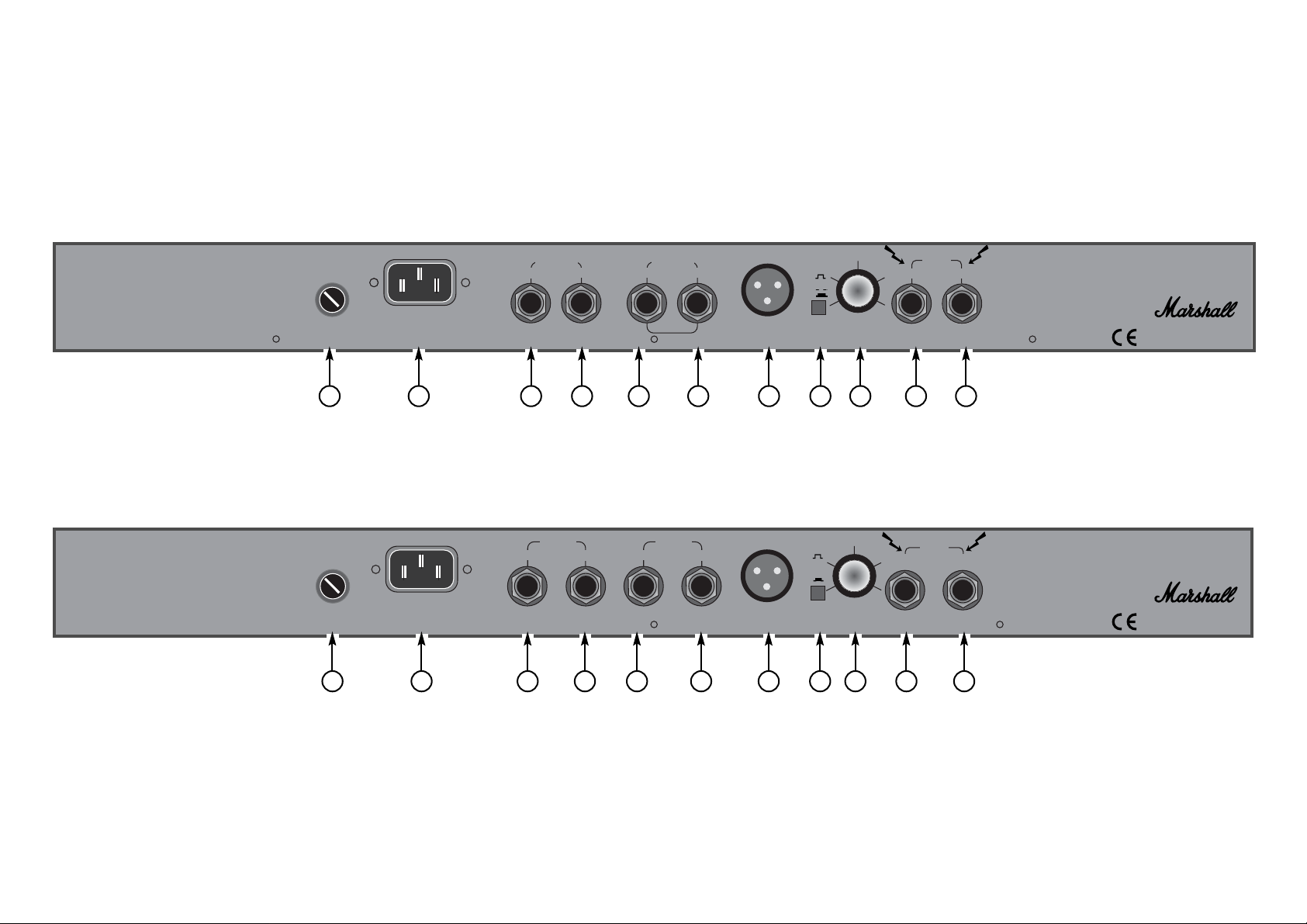
1) Mains Fuse
Protects the amplifier and mains supply in the
event of a fault.
Check the label on the back of the amp for the
correct value. Always replace fuses with the
correct type and rating. It is a wise precaution
to always carry spares.
2) Mains Input
Connects the amplifier to the mains power
supply.
3) Parallel FX Loop Return Jack
Jack socket for connection from the output of
an external effects processor.
Please Note
A parallel FX Loop is best suited for use with
external effects processors which require a
certain amount of dry or uneffected signal in
the overall tone. Time based effects such as
Delay and Chorus are typical examples of the
effects best suited to this type of Loop.
4) Parallel FX Loop Send Jack
Jack socket for connection to the input of an
external effects processor.
5) Series FX Loop Return Jack
Jack socket for connection to the output of an
external effects processor.
6) Series FX Loop Send Jack
Jack socket for connection to the input of an
external effects processor.
Note: The Series Loop is best suited to effects
that require no dry signal such as
Compressors or Graphic Equalisers.
7) D.I. Output
The JCM 600’s D.I. Out is switchable
between a speaker Emulated signal (pre the
power amp), and a non Emulated (post the
power amp ) signal.
The Emulated Output captures the tonality of
Vintage loudspeakers like no other D.I.
furthermore this output is unaffected by the
Master Volume controls therefore allowing
the JCM 600’s output to be turned off whilst
still providing silent recording facilities.
The D.I. Output is via an XLR type connector
which allows this system to be run into either
(a) a line level balanced input (b) a line level
unbalanced input or (c) a low level
unbalanced input.
Please Note
Refer to the JCM 600 XLR Out diagrams
(Below) for correct connections.
8) Pre/Post Switch
Allows Line Out selection between a speaker
Emulated signal (pre the power amp) and
non-emulated (post the power amp).
JCM 601, 602 & JCM600 Head
Rear Panel Functions
✪
Page 6

JAPANESE SPANISH GERMAN
FRENCH
ENGLISH
5
9) Presence Control
This Master Presence control adjusts the
amount of top end frequencies in the overall
tone - adding crispness and bite.
10) Speaker Output
On combo formats of the JCM 600 this jack
is for connection to the internal 16 Ohm
speaker. On the JCM 600 Head this socket is
for connection to an external speaker cabinet,
such as the purpose built JCM C410A
compact 4x10” angled cabinet and/or the
JCM C410B compact 4x10” base cabinet.
11) Speaker Output
For connection to an external 16 Ohm
speaker (The Marshall JCM C12 1x12” and
JCM C212 2x12” cabinet are designed for
use with JCM 600 combos).
On the JCM 600 head this output could drive
a second JCM C410A or JCM C410B
cabinet.
Note
The JCM 600 combos and head will deliver
60 Watts into either one or two 16 Ohm
speakers, ie. 16 or 8 Ohm total impedance.
The unit should not be driven into a load of
less than 8 Ohms.
If you unplug the internal loudspeaker in a
JCM 600 combo it is possible to connect a
single 8 Ohm cabinet to the extension
Speaker Output only. However, when the
internal speaker is connected only a 16 Ohm
extension cabinet may be used.
It is important to follow these instructions as
failure to do so may lead to the amp running
into the wrong impedance, which will
ultimately cause damage.
A
B
C
XLR Channel Input
On Mixer
(Note: Line LevelApprox OdBV)
2 Core Screened Balanced Mic Lead
Unbalanced XLR to Jack Screened Lead
Unbalanced XLR to Jack Screened Lead
Jack Plug Line Level Jack Input On Mixer Etc.
Jack Plug
NC
NC
Low Level Jack Input On Mixer (ie
Mic Input)
JCM 600 XLR Out diagram
✪
3
3
2
2
1
1
3
3
2
1
2
1
3
2
1
3
2
1
3
2
1
3
2
1
Page 7

VOLUME BASS MIDDLE TREBLE
CLEAN
REVERB
OVERDRIVE
REVERB
VOLUME
OVERDRIVE MASTER
0
—
6
4
10
0
—
6
4
10
0
—
6
4
10
0
—
6
4
10
0
—
6
4
10
0
—
6
4
10
0
—
6
4
10
0
—
8
6
4
10
STANDBY
0
1
POWER
0
1
GAINVOLUME
CLEAN
BASS MIDDLE TREBLE
0
2
6
4
10 0
—
6
4
10 0
—
6
4
10
PUSH
CHANNEL
FOOT
SWITCH
INPUT
RED
GREEN
0
4
12
8
200
—
8
6
4
10
(Parallel Mix)
EFFECTS
JCM600
VALVE GUITAR AMPLIFIER
JCM600 Head & JCM601 Combo Front Panel
JCM602 Combo Front Panel
1 2 3 4 5 6 7 8 9 10 11 12 13 14 15 16 18 1917
1 2 3 4 5 6 7 8 9 10 11 12 13 14 15 16 18 1917
JCM600
FOOT
SWITCH
INPUT
PUSH
CHANNEL
VALVE GUITAR AMPLIFIER
4
2
0
CLEAN
4
6
—
10 0
BASS MIDDLE TREBLE
6
10 0
4
—
4
6
—
10
8
6
8
RED
10
GREEN
12
4
0
200
GAINVOLUME
OVERDRIVE MASTER
4
—
0
VOLUME BASS MIDDLE TREBLE
6
10 0
4
—
6
10 0
4
—
6
10 0
4
—
6
10 0
—
(Parallel Mix)
4
EFFECTS
6
10 0
4
6
—
CLEAN
REVERB
—
10 0
OVERDRIVE
4
REVERB
6
—
10 0
4
VOLUME
6
10
STANDBY
0
8
1
POWER
0
1
Page 8
1 2 3 4 5 6 7 8 9 10 11
1 2 3 4 5 6 7 8 9 10 11
JCM601 & 602 Combo Rear Panel
JCM600 Head Rear Panel
CAUTION!:
SAME TYPE AND RATING ONLY. DISCONECT SUPPLY CORD BEFORE
CHANGING FUSE. TO REDUCE THE RISK OF ELECTRIC SHOCK DO NOT
REMOVE COVER. NO USER SERVICEABLE PARTS INSIDE. REFER SERVICING
TO QUALIFIED SERVICE PERSONNEL.
ATTENTION!:
FUSIBLE DE MEME TYPE ET DE MEME CALIBRE. DEBRANCHER AVANT DE
REMPLACER LE FUSIBLE. POUR EVITER LES RISQUES DE DECHARGES
ELECTRIQUES, NE PAS OUVRIR LE COUVERCLE. CET APPAREIL NE COMPORTE
AUCUNE PIECE SUSCEPTIBLE D’ETRE REPAREE PAR
VOS SOINS. FAITES TOUJOURS APPEL A UN TECHNICIEN QUALIFIE
POUR TOUTE REPARATION.
TO REDUCE THE RISK OF FIRE REPLACE FUSES WITH THE
POUR EVITER LES RISQUES D’INCENDIE UTILISER UN
CAUTION!:
SAME TYPE AND RATING ONLY. DISCONECT SUPPLY CORD BEFORE
CHANGING FUSE.TO REDUCE THE RISK OF ELECTRIC SHOCK DO NOT
REMOVE COVER. NO USER SERVICEABLE PARTS INSIDE. REFER SERVICING
TO QUALIFIED SERVICE PERSONNEL.
ATTENTION!:
FUSIBLE DE MEME TYPE ET DE MEME CALIBRE. DEBRANCHER AVANT DE
REMPLACER LE FUSIBLE.POUR EVITER LES RISQUES DE DECHARGES
ELECTRIQUES, NE PAS OUVRIR LE COUVERCLE. CET APPAREIL NE
COMPORTE AUCUNE PIECE SUSCEPTIBLE D’ETRE REPAREE PAR
VOS SOINS. FAITES TOUJOURS APPEL A UN TECHNICIEN QUALIFIE
POUR TOUTE REPARATION.
TO REDUCE THE RISK OF FIRE REPLACE FUSES WITH THE
POUR EVITER LES RISQUES D’INCENDIE UTILISER UN
Emulated
PWR Amp
Line Out
Presence
4
2
0
6
8
10
60 watts RMS into 8/16 .
OUTPUT
Internal
MAINS FUSE
120V—T3A
230V—T1.6A
MAINS INPUT
120V ~ 60 Hz 225 Watts
PARALELL
FX LOOP
SERIES
FX LOOP
Return ReturnSend Send
D.I.OUTPUT
Pin 1—OV, Pin 2—High, Pin 3—Low
MAINS FUSE
120V - T3A
230V - T1.6A
MAINS INPUT
120V ~ 60 Hz 225 Watts
Return
PARALLEL
FX LOOP
Send
Return
SERIES
FX LOOP
Send
D.I.OUTPUT
Pin 1 - OV, Pin 2 - High, Pin 3 - Low
’’
Refer to manual
Se referer au manuel
Emulated
PWR Amp
Line Out
Presence
4
2
0
6
8
10
60 watts RMS into 8/16 .
OUTPUT
Main
16
Extension
Ext 16
Main 8
WARNING!:
OR ELECTRIC SHOCK DO NOT EXPOSE THIS EQUIPMENT TO RAIN OR MOISTURE.
THIS APPARATUS MUST BE EARTHED.
AVIS!:
RISQUES D’INCENDIE ET DE DECHARGES ELECTRIQUES, N’EXPOSEZ JAMAIS CET
APPAREIL A L’HUMIDITE OU A LA PLUIE.
CONNECTER CET APPAREIL A LA TERRE.
WARNING!:
OR ELECTRIC SHOCK DO NOT EXPOSE THIS EQUIPMENT TO RAIN OR MOISTURE.
THIS APPARATUS MUST BE EARTHED.
AVIS!:
RISQUES D’INCENDIE ET DE DECHARGES ELECTRIQUES, N’EXPOSEZ JAMAIS CET
APPAREIL A L’HUMIDITE OU A LA PLUIE.
CONNECTER CET APPAREIL A LA TERRE.
SHOCK HAZARD. DO NOT OPEN. TO REDUCE THE RISK OF FIRE
RISQUE DE CHOC ELECTRIQUE. NE PAS OUVRIR. POUR EVITER LES
Made in England by:
Marshall Amplification plc,
Bletchley, Milton Keynes, England.
SHOCK HAZARD. DO NOT OPEN. TO REDUCE THE RISK OF FIRE
RISQUE DE CHOC ELECTRIQUE. NE PAS OUVRIR. POUR EVITER LES
Made in England by:
Marshall Amplification plc,
Bletchley, Milton Keynes, England.
 Loading...