


Responder 3000

Operator's Manual
Version 2
227 490 02 GA (e) Revision C


Contents
227 490 02-C Marquette Responder® 3000 3
1 Intended Use and Functional Description 5
2 Controls and Indicators 6
3 Putting the Device into Operation and Perf ormance Check 9
4 Manual Defibrillation 18
4.1 Defibrillator Application Guidelines 18
4.2 Non-Synchronized Defibrillation 19
4.3 Synchronized Defibrillation (Cardioversion) 26
5 Semiautomatic Defibrillation 30
6 Pacemaker 36
7 Displaying and Monitoring the ECG 41
8 12-Lead ECG Analy sis Program (12SL
TM
)46
9 Pulse Oximetry (SpO
2
)49
10 Capnometry (etCO
2
)54
11 Memories of the Marquette Responder® 3000 58
12 Recording 61
13 Defibrillator Setup 63
14 Battery Power Operation 67
15 Test Discharge 70
16 Operation in the Vehicle Mounting Unit,
Mounting the AC Power Adapter 73
17 Error and System Messages 74
18 Cleaning, Maintenance 75
19 Technical Specifications 78
20 Order Information 84
Appendix
The Arrhythmia Detection Program 87
EC Declaration of Conformity 88
Index 89
Revision History
This manual is subject to the Marquette Hellige change order service. The revision
code, a letter that follows the document part number, changes with every update of the
manual.
P/N / Index Date Comment
227 490 02-A January 1999 Initial Release
227 490 02-B October 1999 Version 2
227 490 02-C January 2000 ECO 064 064
General Information
4 Marquette Responder® 3000 227 490 02-C
General Information
The product Marquette Responder
®
3000 bears
the CE marking
CE-366
indicating its compliance with the provisions
of the Council Directive 93/42/EEC about
medical devices and fulfills the essential re-
quirements of Annex 1 of this directive.
The product complies with the electromagnetic
immunity requirements of standard IEC
60601-1-2/EN 60601-1-2 "Electromagnetic
Compatibility - Medical Electrical Equip-
ment".
The radio-interference emitted by this device
is within the limits specified in CISPR11/EN
55011, class A.
The device is designed to comply with I EC 60601
requirements. It is a protection class I device
and has an internal power source. It is classi-
fied as an MDD class IIb device.
The CE mark covers only the accessories
listed in the "Order Information" chapter .
This manual reflects software version 2.
This manual is an integral part of the device. It
should always be kept near the device. Close
observance of the information given in the
manual is a prerequisite for proper device
performance and correct operation and ensures
patient and operator safety. Please note that
information pertinent to several chapters is
given only once. Therefore, carefully read
the manual once in its entirety.
The symbol means: Consult accompany-
ing documents. It indicates points which are of
particular importance in the operation of the
device.
This manual is in conformity with the dev ice
specifications and standards on safety of elec-
tromedical equipment valid at the tim e of
printing. All rights are reserved for devices,
circuits, techniques, software programs, and
names appearing in this manual.
On request Marquette Hellige will provide a
service manual.
The Marquette Hellige quality management
system complies with the standards DIN EN
ISO 9001 and EN 46001.
The safety information given in this manual is
classified as follows:
Danger
indicates an imminent hazard. If not avoided, the
hazard will result in death or serious injury.
Warning
indicates a hazard. If not avoided, the hazard can
result in death or serious injury.
Caution
indicates a potential hazard. If not avoided, this
hazard may result in minor personal injury and/or
product/property damage.
To ensure patient safety, the specified
measuring accuracy, and interference-free
operation, we recommend to use only original
Marquette Hellige components. The user is
responsible for application of accessories from
other manufacturers.
The warranty does not cover damage resulting
from the use of unsuitable accessories and
consumables from other manufacturers.
Marquette Hellige is responsible for the effects
on safety, reliability, and performance of the
device, only if
−
assembly operations, extensions, readjust-
ments, modifications, or repairs are carried
out by Marquette Hellige or by persons
authorized by Marquette Hellige,
−
the device is used in accordance with the
instructions given in this operator's manual.
Marquette Hellige GmbH 2000
Postfach 600265
79032 Freiburg, Germany
Telephone +49 761 45 43-0

Intended Use and Functional Description
227 490 02-C Marquette Responder® 3000 5
1 Intended Use and Functional Description
The Marquette Responder® 3000 is a lightweight,
portable defibrillator with ECG monitor and
integrated recorder.
It is perfectly geared both to hospital and to
prehospital use; in conjunction with the vehicle
mounting unit, it can also be used in an ambulance.
There are two versions of the Marquette
Responder® 3000:
−
a version for manual defibrillation,
−
a version for semiautomatic defibrillation
which can be switched to manual operation.
Both versions are capable of delivering synchro-
nized and non-synchronized defibrillation shocks.
The following paddle types can be used with the
defibrillator: hard paddles (with integrated contact
surfaces for children), adhesive electrodes and
internal spoons.
The device features can be upgraded with the
following options:
−
a program for ECG measurement and interpre-
tation (12SL),
−
an etCO
2
measurement system (capnometry),
−
an SpO
2
measurement system (pulse oximetry),
−
a transcutaneous pacemaker.
1
2
3
3
2
Analyse
Sync
1
2
5
7
10
20
30
50
100
150
200
300
360
Print Event
Autoseq
On
Off
Start
Pause
+ —
Dem
Fix
P/min
+ —
mA
Pacer
Figure 1-1. Marquette Responder® 3000
The color concept for the displayed information
lets you see at a glance whether
−
the parameter reading is within the alarm limits
(green),
−
a technical fault is reported (blue),
−
an alarm is reported (red),
−
the system displays a message (yellow).
The defibrillator has the following memories for
storage and documentation of the relevant
procedure data:
−
an event memory,
−
an ECG memory,
−
a trend memory, and
−
a memory for the 12SL analysis results.
The integrated 3-channel recorder can be started
manually and automatically.
The defibrillator is powered from
−
an optional AC power adapter which is
permanently attached to the defibrillator, or
−
1 or 2 plug-in batteries, or
−
the vehicle mounting unit / wall mount unit.
Batteries are recharged via:
−
the optional AC power adapter
−
the optional charging unit, or
−
the optional vehicle mounting system.
Biocompatibility
The parts of the product desc ribed in this operator
manual, including all accessories, that come in
contact with the patient during the intended use,
fulfill the biocompatibility requirements of the appli-
cable standards. If you have ques tions in t his matter ,
please contact Marquette Hellige GmbH or its repre-
sentatives.
Controls and Indicators
6 Marquette Responder® 3000 227 490 02-C
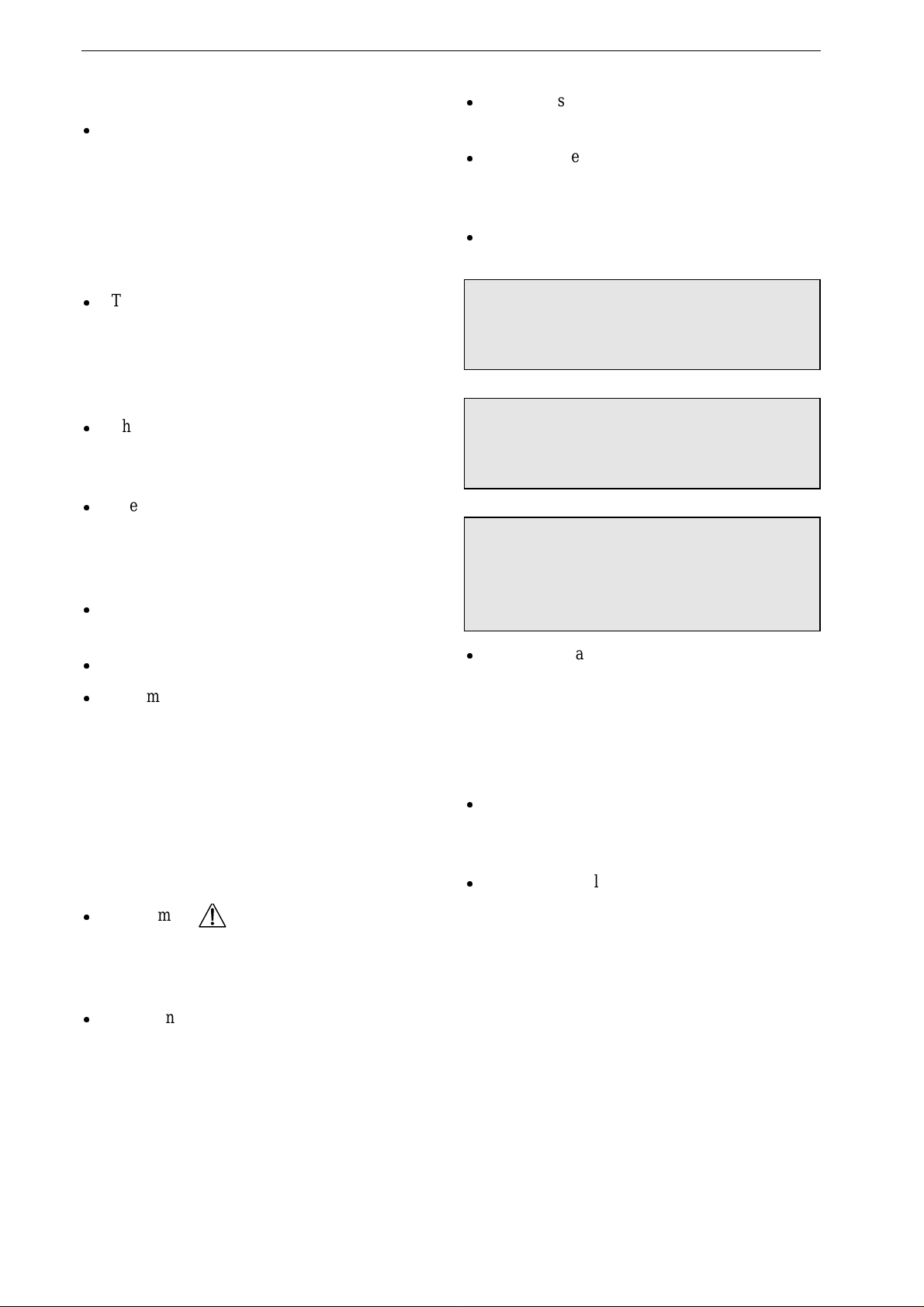
2 Controls and Indicators
The Device
1
2
3
3
2
Analyse
Sync
1
2
5
7
10
20
30
50
100
150
200
300
360
Print Event
Autoseq
On
Off
Start
Pause
+ —
Dem
Fix
P/min
+ —
mA
Pacer
1
18
19
20
21
22
23
25
24
27
28
29
30
26
31
17
2
3
4
9
10
8
7
11
1316 15 1214
5
6
Figure 2-1. Controls and indicators of the Marquette Responder® 3000

Controls and Indicators
227 490 02-C Marquette Responder® 3000 7
1
Connector for exchange of the defibrillation
electrodes (switch off the device before ex-
changing the electrodes!)
2
APEX paddle
3
Infrared interface
4
Battery with "Test" button and charge level
indication
5
Button to unlock right battery for removal
6
Energy selector, ON/OFF switch
7
Indicator, yellow, flashes to the QRS rhythm
in synchronized mode
8
Button to enable and disable the synchronized
mode (cardioversion)
9
Button to initiate ECG analysis in the
semiautomatic mode (only on semiautomatic
defibrillator models)
10
Button to initiate defibrillator charging and to
trigger the shock (together with button 11)
when adhesive pads or internal spoons are
used
11
Button to trigger the defibrillation shock
(together with button 10) when adhesive pads
or internal spoons are used
12
1-Volt ECG output
13
etCO
2
signal input (optional)
14
SpO
2
signal input (optional)
15
Function keys F1 to F5
16
ECG signal input
17
Event marker button
18
Button to start and stop the recorder
19
Button to change the pacer output (current)
20
Button to change the pacer rate
21
Button to pause the pacer (without changing
the settings)
22
Button to select the pacer mode (fixed rate,
demand)
23
Button to unlock left battery for removal
24
Button to turn the pacemaker on and off
25
Indicator, yellow: blinks with each delivered
pacing pulse
26
Button to open paper compartment
27
Battery with "Test" button and charge level
indication
28
Indicator, green: is lit when defibrillator is
powered from an external source (mains,
ambulance)
29
Indicator, yellow
blinking: left battery charging
on: left battery charged
off: left battery missing or partially charged,
no external power source connected
30
Indicator, yellow
blinking: right battery charging
on: right battery charged
off: right battery missing or partially charged,
no external power source connected
31
STERNUM paddle
Explanation of symbols used on the device
Consult accompanying documents
Caution, High Voltage
Type CF signal input: highly insulated,
suitable for intracardiac application,
defibrillation-proof
Type CF signal input: highly insulated,
suitable for intracardiac application
Battery charging
+
Housing without battery (to close the
battery slot)
Standby mode (line power operation)
Audio alarm OFF
Defibrillation Electrodes
8 Marquette Responder® 3000 227 490 02-C
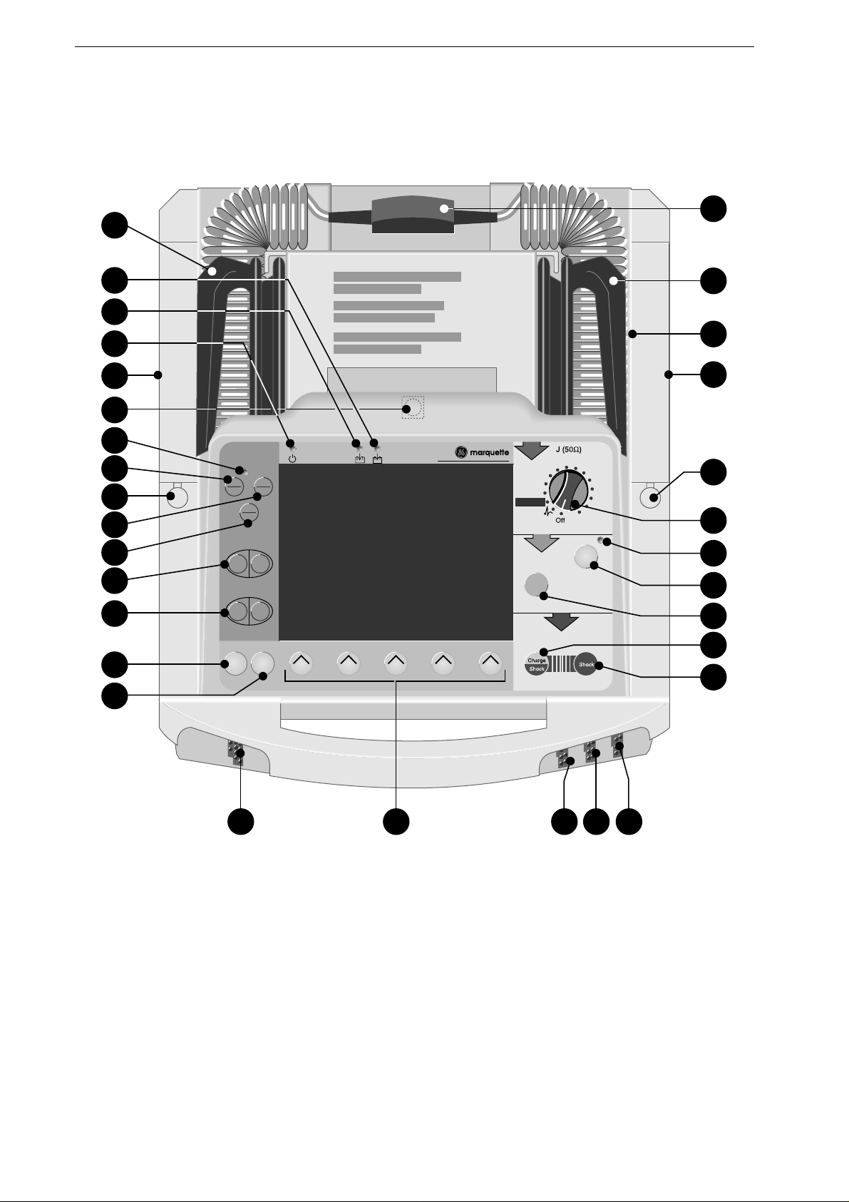
Defibrillation Electrodes
SHOCK
3
CHARGE
2
APEX
Figure 2-2. Hard paddle
a
d
bc
Figure 2-3. Electrode for internal defibrillation
Figure 2-4. Disposable adhesive electrode
(external defibrillation, pacing)
Hard Paddles
Hard paddles are the electrodes commonly used
for external, transchest defibrillation. There is a
special Apex paddle and a Sternum paddle.
For delivery of the defibrillation shock, the
paddles are placed directly on the body surface.
Before use, however, an ample amount of
electrode gel must be spread onto the paddles.
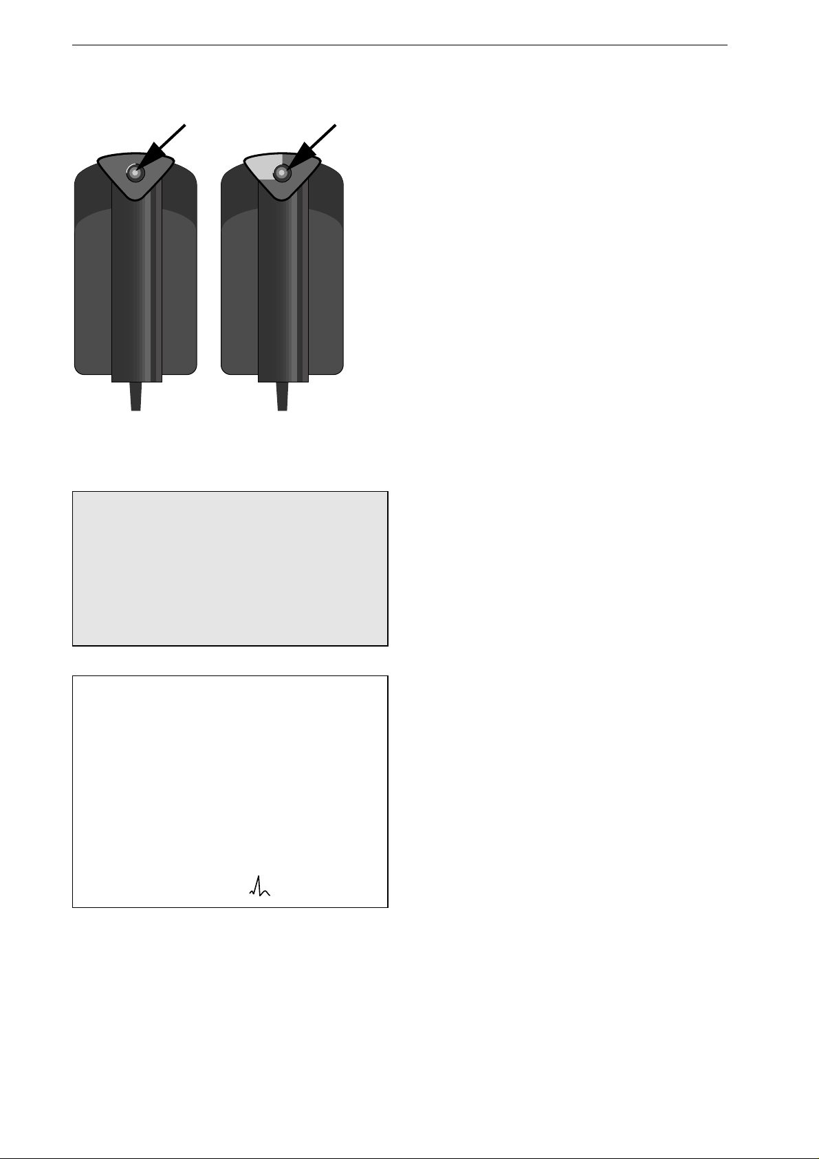
Both paddles have a shock button: The shock
button on the Apex paddle is used to initiate
defibrillator charging; afterwards the defibrillation
shock is triggered by pushing both shock buttons.
The paddles can also be used to acquire the ECG
signal.
A smaller contact surface for defibrillation of
children is integrated in the paddles (see "Defi-
brillation of Children" in section 4.2).
Electrodes for Internal Defibrillation
Electrodes for internal defibrillation consist of a
contact spoon (
a
, Figure 2-3), a handle
b,
and a
counter nut
c
.
The spoon must match the size of the heart and
have full contact with the myocardium. There is a
choice of 3 different spoon sizes.
The electrodes as well as their connection cable
must be sterilized before each use.
An internal defibrillation is either performed with
two
spoon electrodes or with
one
spoon electrode
and a so-called "external counter electrode" (
d
,
Figure 2-3) which is placed under the patient and
in the immediate vicinity of the heart.
Defibrillator charging and release of the defibril-
lation shock are initiated with buttons on the
device.
Disposable Adhesive Electrodes
Disposable adhesive electrodes are used both for
defibrillation and for pacing. These electrodes are
self-adhesive and pregelled. They are connected by
means of a special cable and may remain attached
to the patient for a maximum of 24 hours.

Putting the Device Into Operation and Performance Check
227 490 02-C Marquette Responder® 3000 9
3 Putting the Device into Operation and Performance Check
Safety information
Danger
Explosion Hazard – The device is not designed for
use in areas of medically used rooms where an
explosion hazard may occur. An explosion hazard
may result from the use of flamm able anesthetics,
skin cleansing agents and disinfectants.
Also, it is not permitted to operate the defibrillator
in an oxygen-enriched environment or in the
presence of flammable substances (gas) or anes-
thetics.
Oxygenation in the vicinity of the defibrillation
electrodes must be strictly avoided. Temporarily
interrupt the oxygen supply.
Warning
Shock Hazard — Observe the follo wing warnings.
Otherwise the lives of the patient, the user and
bystanders are in danger.
-
The Marquette Responder® 3000 is a high-
voltage electrotherapy device and must be
handled by qualified and specially trained per-
sonnel. Improper use of the device can endan-
ger life. Always follow the instructions given
in the operator's manual.
-
When equipped with the AC power adapter, do
not use the defibrillator outdoors because the
power adapter is not splash-proof.
-
Before using the device, the operator must
ascertain that it is in correct working order
and operating condition. In particula r, a ll
connectors, electrodes as well as sensors and
probes must be checked for signs of damage.
Damaged parts must be replaced immediately,
before use.
-
When disconnecting the device from the power
line, remove the plug from the wall o utlet first,
before disconnecting the cable from the de-
vice. Otherwise there is a risk of coming in
contact with line voltage by inadvertently in-
troducing metal parts in the socket o f the
power cord.
-
As a general rule, utmost caution is advised
for intracardiac application of medical techni-
cal devices. Great care must be exercised to
prevent that conductive parts (connectors,
electrodes, transducers) connected to the iso-
lated patient signal input come in co ntact with
other grounded conductive parts, as this could
bridge the patient's isolation and cancel the
protection provided by the isolated input.

Putting the Device Into Operation and Performance Check
10 Marquette Responder® 3000 227 490 02-C
-
Electrically conductive contact with parts
connected to the heart (pressure transducers,
metal tube connections and cock s, guide
wires, electrode catheters and the metal parts
of syringes) must be avoided at all cost.
When using devices intracardially, observe
these guidelines:
-
always wear isolating rubber gloves;
-
parts with a conductive connection to the
heart must be isolated from ground;
-
do not use tube fittings and stopcock s made
of metal, if possible;
-
when connecting the heart catheter, observe
these guidelines:
- the connection must be isolated
- all electrodes must be attached to the pa-
tient and secured against inadvertent dis-
connection or they must be isolated and
protected against inadvertent contact (oth-
erwise electrodes that become disconnected
could bring the patient in contact with
ground).
-
When devices are used intracardially, the
annual Technical Inspections are manda tory.
During intracardiac application of medical
electrical devices, a defibrillator and pace-
maker, both checked for proper functioning,
must be readily available.
-
Ensure that no conductive connection between
the patient and bystanders exists during defi-
brillation.
-
The mains plug must be connected to an
appropriate power supply with a non-fused
earthed wire. If these requirements cannot be
guaranteed, connect the device to the ambu-
lance power supply or operate it on battery
power.
-
Do not use multiple portable socket outlets
(MPSO) to connect the device to the power
line.
-
Devices may be connected to other devices or
to parts of systems only when it has been made
certain that there is no danger to the patient,
the operators, or the environment as a result.
In those instances where there is any element
of doubt concerning the safety of connected
devices, the user must contact the manufac-
turers concerned or other informed experts as
to whether there is any possible danger to the
patient, the operator, or the environment as a
result of the proposed combination of devices.
Standards IEC 60601-1-1/EN60601-1-1 must
be complied with in all cases.
-
The device (without AC power adapter) is
suitable for application in a humid environ-
ment provided the regulations concerning
drip-proof equipment of IEC 60601/EN 60601
are strictly observed. However, do not defi-
brillate patients in a very moist or wet envi-
ronment, unless absolutely necessary. Always
dry the defibrillation electrodes and connec-
tion cables prior to defibrillatio n.

Putting the Device Into Operation and Performance Check
227 490 02-C Marquette Responder® 3000 11
Warning
-
Equipment Failure — Magnetic and electrical
fields are capable of interfering with the
proper performance of the device. For this
reason make sure that all external devices op-
erated in the vicinity of the defibrillator com -
ply with the relevant EMC requirements. X-
ray equipment, MRI devices, radio systems,
and cellular telephones are a possible source
of interference as they may emit higher levels
of electromagnetic radiation.
Keep the defibrillator away from these d evices
and verify the defibrillator performa nce before
use.
-
Equipment Failure — Similarly, the defibril-
lator may disturb equip ment operating in its
vicinity when charging or delivering the
shock. Verify the performance of these devices
before use.
-
Suffocation Hazard — Dispose of the pack-
aging material, observing the applicable
waste-control regulations. Keep the packaging
material out of children's reac h.
Caution
-
Equipment Damage, Shock Hazard — De-
vices intended for emergency application must
not be exposed to low temperatures during
storage and transport to avoid moisture con-
densation at the application site. Wait until all
moisture has vaporized before using the de-
vice.
-
Equipment Damage — Exercise great care
when using HF surgery equipment on the pa-
tient at the same as the defibrillator. As a g en-
eral rule, the distance between the ECG and
defibrillation electrodes and the HF surg ery
electrodes should not be less than 15 cm. If
this is not ensured, disconnect the electrodes
and transducer leads while using the HF sur-
gery device.
-
Equipment Damage — Avoid defibrillating
repeatedly into open air or with the paddles
shorted together, because the device tempera-
ture may increase to an inadmissible level due
to the internal safety discharges.
Literature
Medical Device Directive of August 2, 1994
EN 60601-1: 1990 + A 1: 1993 + A 2: 1995
Medical electrical equipment. General require-
ments for safety.
EN 60601-1-1: 9/1994 + A1: 12/1995
General requirements for safety. Requirements for
the safety of medical electrical systems.
IEC-Publication 513/1994: Fundamental aspects of
safety standards for medical equipment.
Putting the Device Into Operation and Performance Check
12 Marquette Responder® 3000 227 490 02-C
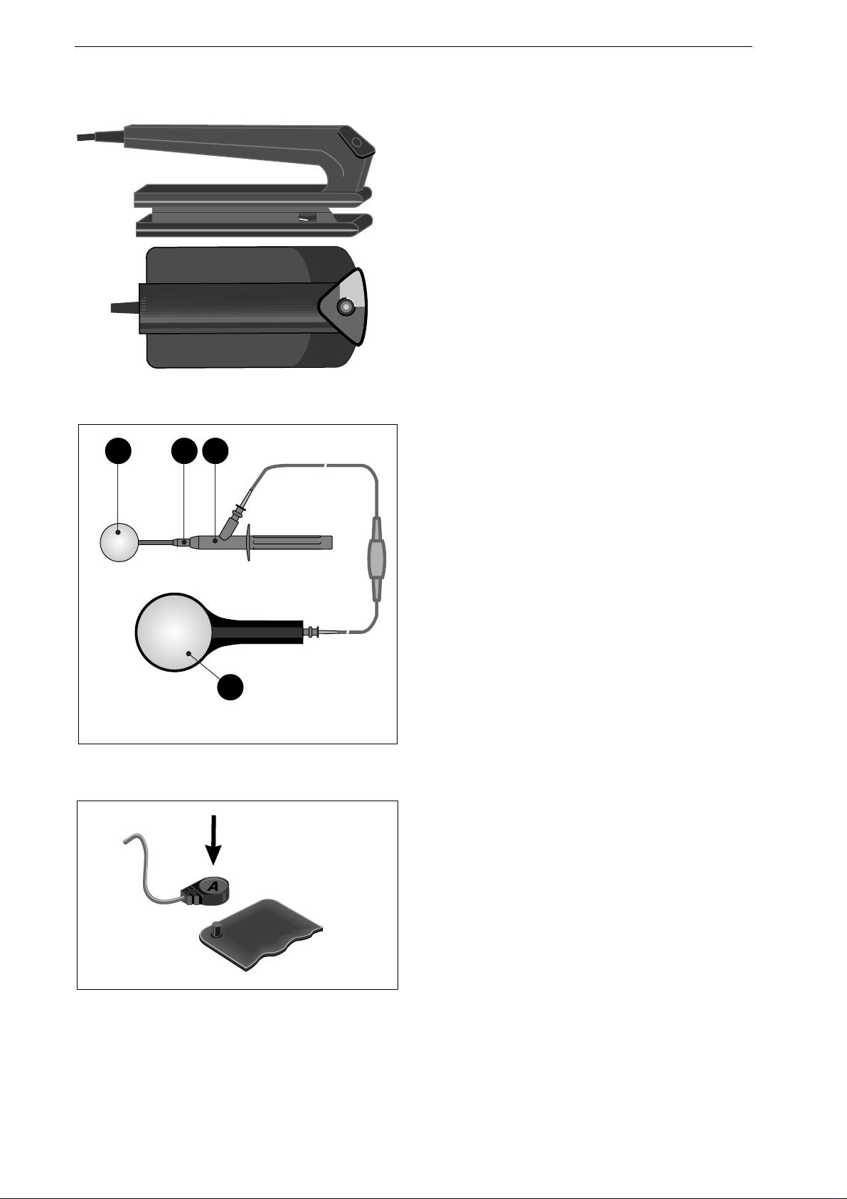
Figure 3-1. Defibrillator with AC power adapter
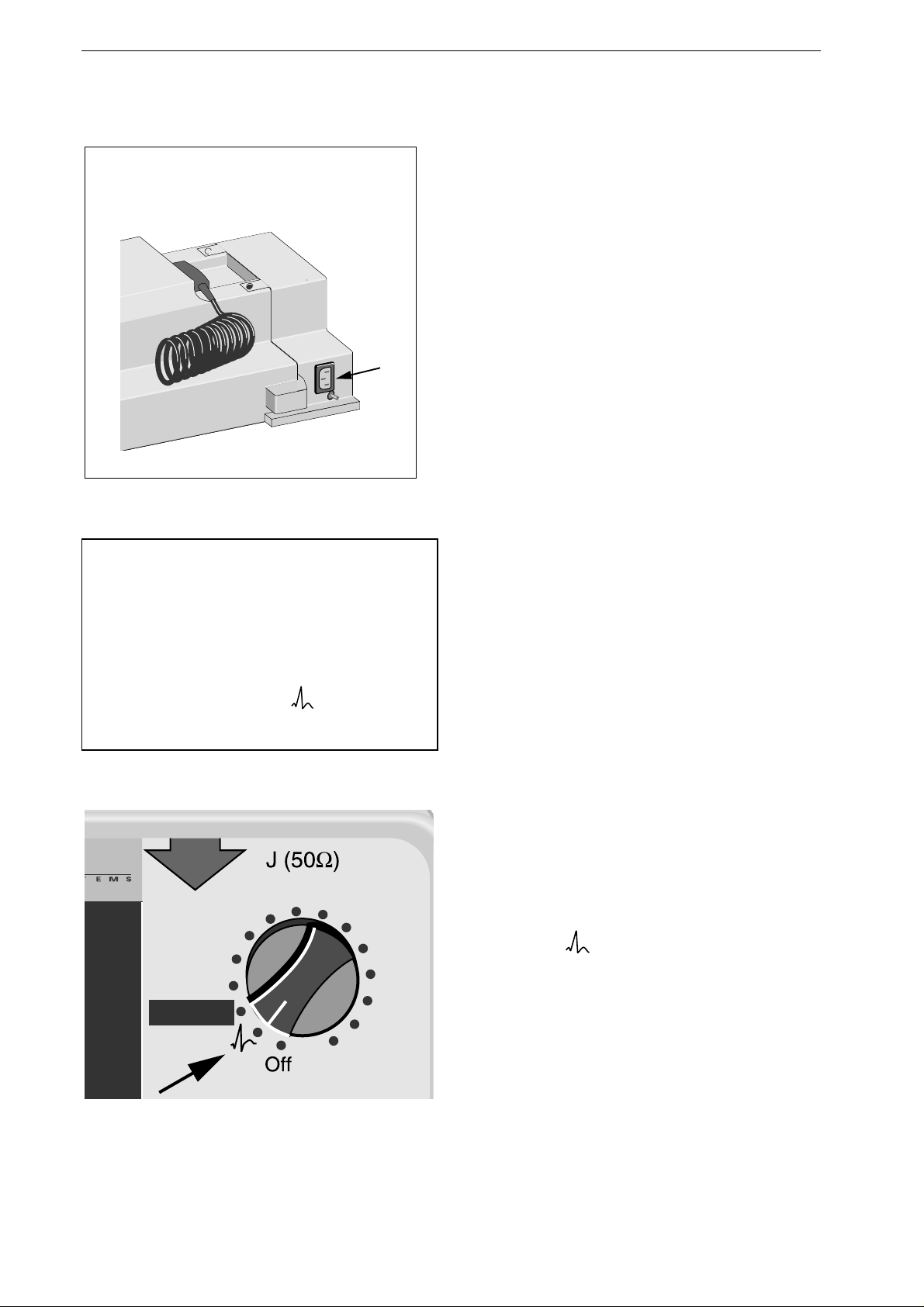
Note
The Marquette Responder® 3000 is switched on
and off with the energy selector. Once you are
familiar with the device operating ro utines, this
control lets you turn on the device and select the
required defibrillation energy in one action. No
shock can be delivered in the po sitio n of the
energy selector.
1
2
5
7
10
20
30
50
100
150
200
300
360
Autoseq
Figure 3-2. Turning the defibrillator on
Power Supply
The defibrillator can be powered
−
from the power line (requires AC power
adapter, P/N 205 108 01, Figure 3-1),
−
from the ambulance power supply system
(requires vehicle mounting unit,
P/N 202 317 01),
−
from the wall mount unit (P/N 202 317 03)
−
from 1 or 2 rechargeable batteries (mains-
independent).
Batteries are recharged by one of the following
methods:
−
in the defibrillator, when the defibrillator is
connected to the power line or to the ambulance
power supply system, or
−
by means of the separate charging unit ASU
3000 (P/N 701 279 01).
If you prefer to operate the device mains-
independent, ensure that the batteries are charged
(chapter 14 "Battery Power Operation").
Please refer to chapter 16 for information on
operating the device in the vehicle mounting unit
and on installing the AC power adapter.
Turning the Defibrillator On
•
Connect the device to the power supply.
•
Switch on the device by turning the energy
selector to
(defibrillation shocks cannot be
delivered in this position).
The test screen appears and the device emits a
short audio signal.
On the test screen you can see the software version
and a message referring to the self-test. The three
color blocks in red, green and blue are displayed to
verify the correct representation of the colors.
After the self-test the standard screen appears
(Figure 3-3).
Putting the Device Into Operation and Performance Check
227 490 02-C Marquette Responder® 3000 13
ECG
ECG
Electrode
15.07.1999 09:05:00
160 / 40
bpm
SpO2
etCO2
QRSPulse
Tone
OFF
Next
Menu
semiautom.
0
Paddle
SpO2
parameter
window
etCO2
parameter
window
pacemaker
window
g
a fedcb
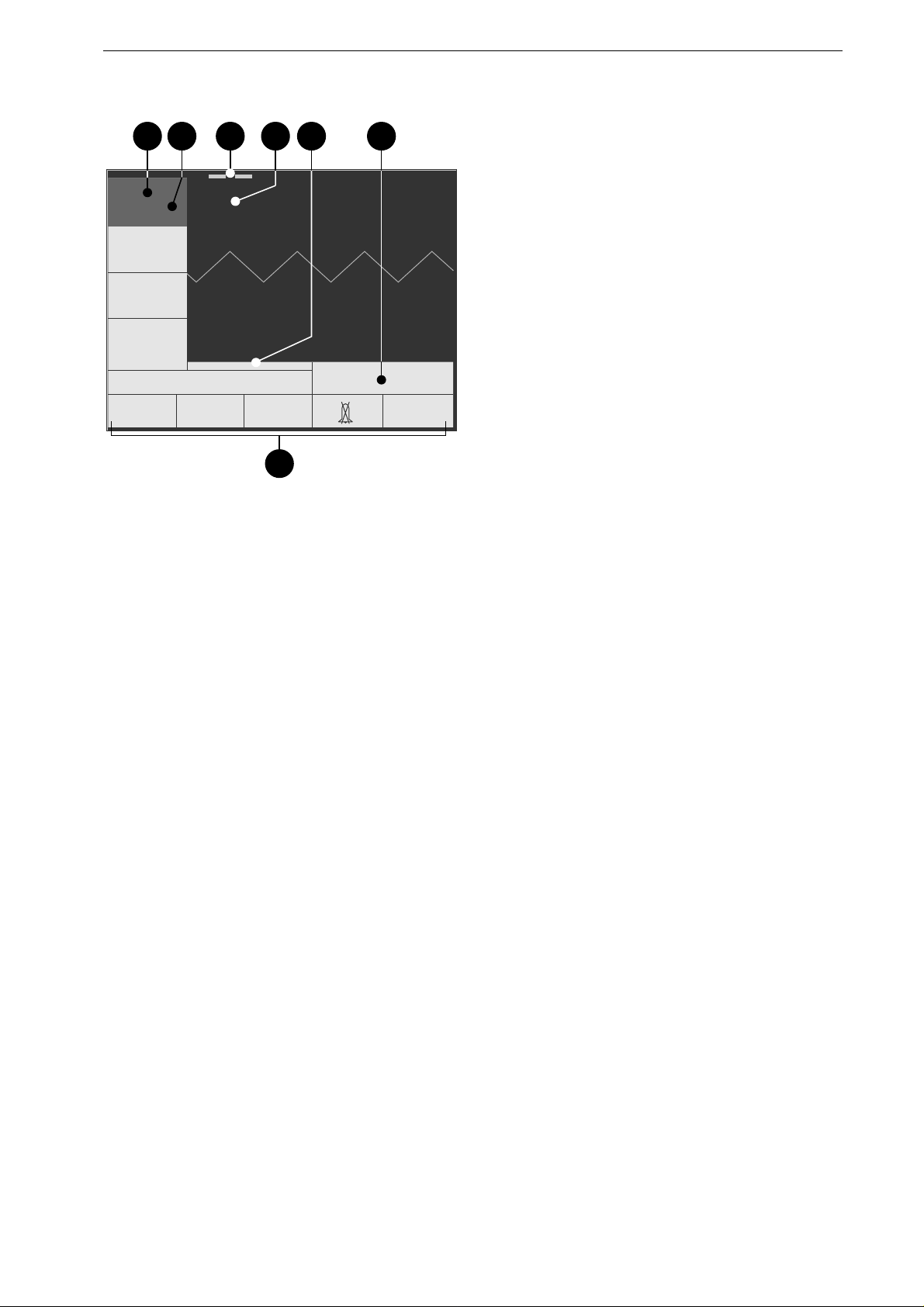
Figure 3-3. Standard screen display
a measured heart rate/pulse rate
b selected limit values
c battery charge level indication
d ECG lead (ECG signal acquired
via "Paddle")
e date, time
f selected operating mode,
defibrillation energy
g menu
The Standard Screen Display
This is the information presented on the standard
screen display:
−
windows for heart / pulse rate, SpO
2
and etCO
2
readings including the limit values
a
,
b
−
battery charge level
c
−
ECG lead
d
−
window for ECG, SpO
2
and etCO
2
waveforms
−
window indicating operating mode and
defibrillation energy
f
−
date and time
e
−
menu
g
.
The color concept for the displayed information
lets you see at a glance whether
−
the parameter reading is within the alarm limits
(green),
−
a technical fault is reported (blue),
−
an alarm is reported (red),
−
the system displays a message (yellow).
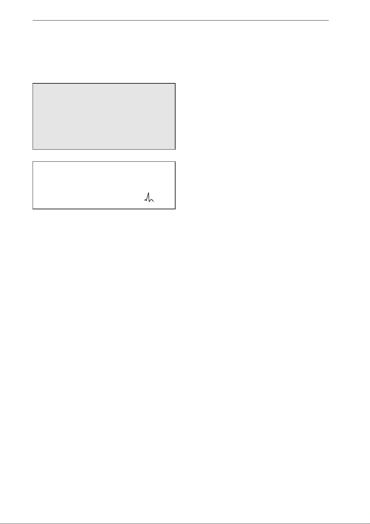
If the device does not receive an ECG signal, the
HR window is blue (technical fault) and a
sawtooth signal is displayed instead of an ECG.
The SpO
2
and etCO
2
parameter windows are also
blank and the corresponding waveforms are
missing when the required sensors are not
connected.
Putting the Device Into Operation and Performance Check
14 Marquette Responder® 3000 227 490 02-C
↓
ECG SpO2
etCO2
QRSPulse
Tone
OFF
Next
Menu
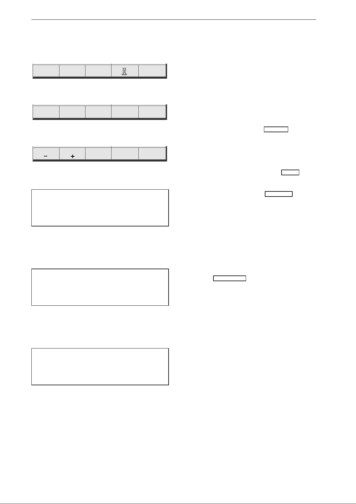
Figure 3-4. Main menu
↓
Filter
ON
Assign
Channel
Waveform
DisplayMemory
Previous
Menu
Figure 3-5. Main menu, page 2
↓ ↓ ↓
Contrast Contrast Display
Flip
Previous
Menu
Select
Color
Figure 3-6. Display menu
Note
The main menu will automatically reappear, when
no button is activated for a period of 30 seconds.
Note
Press F5 for about 2 seconds to return directly to
the main menu.
Note
Enter your own settings in the column at the far
right (with date and signature).
Display Flip
The screen display can be rotated 180° to adapt it
to the operating position of the defibrillator. The
display can be flipped permanently from the setup
menu or temporarily as outlined below. You can
also set up the system to flip the display automati-
cally when the defibrillator is inserted in the
vehicle mounting unit (chapter 13 "Defibrillator
Setup").
•
In the main menu, select
F5
Next Menu
(Figure
3-4).
You will see page 2 of the main menu (Figure 3-
5).
•
Display the Display menu with
F4
Display
(Figure 3-6).
•
To flip the display, press
F4
Display Flip
.
Contrast adjustment
•
Adjust the contrast from the Display menu with
F1
and
F2
.
Adjusting Maximum Contrast (Select Color)
•
Adjust the maximum contrast from the Display
menu with
F3
.
•
Press
F5
Previous Menu
for about 2 seconds to
return directly to the main menu.
System Setup
The device has a configuration menu which allows
you to customize some of the functions to suit your
personal requirements. These settings will be
retained. The table at right shows all device
settings for which customer defaults can be
selected, as well as the factory defaults.
The information given in this manual is based
on a defibrillator with the factory defaults.
In chapter 13 "Defibrillator Setup" you will find
instructions on setting up the defibrillator. The
same chapter explains how to change the language
and how to restore the factory defaults.

Putting the Device Into Operation and Performance Check
227 490 02-C Marquette Responder® 3000 15
Parameter Comment Factory
Defaults
Options User Setup
ALARM LIMITS
HR Limit 40/160 OFF, 15 to 300
increments of 5
SpO
2
Limit
---/90 OFF, 60 to 99
etCO
2
Limit
---/20 OFF, 5 to 76
increments of 1
ECG
Print on Alarm autom. recorder start on violation of limit
value
off on/off
Lead Fail Alarm audio signal indicating disconnected
electrode
off 30 s/off
Alarm Tone audio sign al indicating violation of a n
alarm limit
off on/off
QRS Beep off low/middle/high / off
Muscle Filter suppression of motion artifact on on/off
Gain for ECG display 1 cm/mV 0.5; 1; 2 cm/mV
Lead Channel 1 I standard leads,
paddle acquisition
Lead Channel 2 II standard leads, SpO
2
Lead Channel 3 III standard leads, SpO
2
,
etCO
2
DEFIB
Print on shock automatic recorder start on shock on on/off
Operating Mode** c hoice of the operating mode semiautomatic/button semiautom./button
semiautom./password
semiautom.
manual
Autosequence energy selection 200 J, 200 J, 360 J 150 to 360 J per shock
Pacemaker default pacer rate 60 P/min 30 to 200 P/min
SpO
2
C-LOCK C-Lock ECG synchronization off on/off
SpO
2
Integ. Time SpO
2
integration time 8 s 4 s, 8 s, 12 s
DATE/TIME**
Change clears all existing settings.
Date Format** day.mon.year day.mon.year
mon/day/year
Entry of date and time
DEVICE
Display
screen display (SmartFlip = disp lay flips
automatically when defibrillator is placed
in vehicle mounting unit)
normal normal, reverse,
SmartFlip
Volume valid for all audio signals high high/low/middle
Cont. Printout continuous recording or 14-second strip off on/off
Analysis continuous ECG analysis on on/off
AC Line Filter** elimination of AC line interference 50 Hz off/50 Hz/60 Hz
Language** selection of the language
Factory Default restores factory defaults
User** text or name (20 characters)
PASSWORD**
entry of the password 111 000/999
for config** protects access to configuration menu off on/off
EVENT TEXTS** entry of event texts
BATTERY battery maintenance program
on/off
OPTIONS entry of option code to unlock option
** not affected by reactivation of factory defaults
Putting the Device Into Operation and Performance Test
16 Marquette Responder® 3000 227 490 02-C
ECG
ECG
Electrode
15.07.1999 09:05:00
160 / 40
bpm
SpO2
etCO2
QRSPulse
Tone
OFF
Next
Menu
semiautom.
Paddle
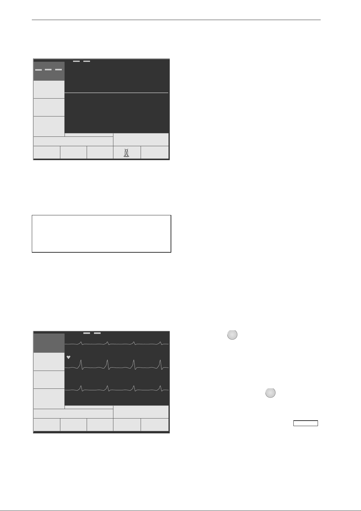
Figure 3-7. Standard screen display of a
defibrillator ready for operation (no
ECG, SpO
2
and etCO
2
signal avail-
able)
Note
A special simulator is required to test the defib ril-
lator performance in the semia uto matic mode.
Text 1
ECG
I
II
III
15.07.1998 09:05:00
160 / 40
bpm
Text 2 Text 3 Text 4
Next
Menu
semiautom.
62
Figure 3-8. Event texts
Performance Check
A performance check must be carried out before
each use.
The check includes:
−
a visual inspection of the device, the cables and
the electrodes for signs of mechanical damage,
−
verification of the functional readiness of the
device,
−
delivery of a test discharge.
After power-up and during operation, the
Marquette Responder® 3000 runs automatic self-
tests. If malfunctions are identified, an error
message will be displayed (see chapter 17 "Error
and System Messages"). In this situation do not
put the device into service.
In all other cases you will see the standard screen
display (Figure 3-7) and the device is ready for
use.
Now verify that the defibrillation shock is
correctly delivered by triggering a test discharge
(chapter 15 "Test Discharge").
If the energy of the test discharge is not within the
specified limits, a defibrillation is possible all the
same (it is the user's decision whether or not to
employ the defibrillator). However, the device
must be immediately checked and repaired by a
service technician.
Event Button
You can use the
Event
button to mark specific
events (e.g. administration of medications). When
you press this key, the corresponding point in time
is earmarked in the full-disclosure ECG. Further-
more, you can assign a maximum of 8 "event"
texts to the function keys
F1
to
F4
(e.g. names of
medications). When you press
Event
these texts
appear in the menu line (Figure 3-8). You can
press one of the function keys to assign the
corresponding text to the event. With
F5
Next Menu
you can display the next line of 4 texts. (Refer to
chapter 13 "Device Setup" for instructions on
entering event texts.)
Putting the Device Into Operation and Performance Test
227 490 02-C Marquette Responder® 3000 17
3
2
Analyse
Sync
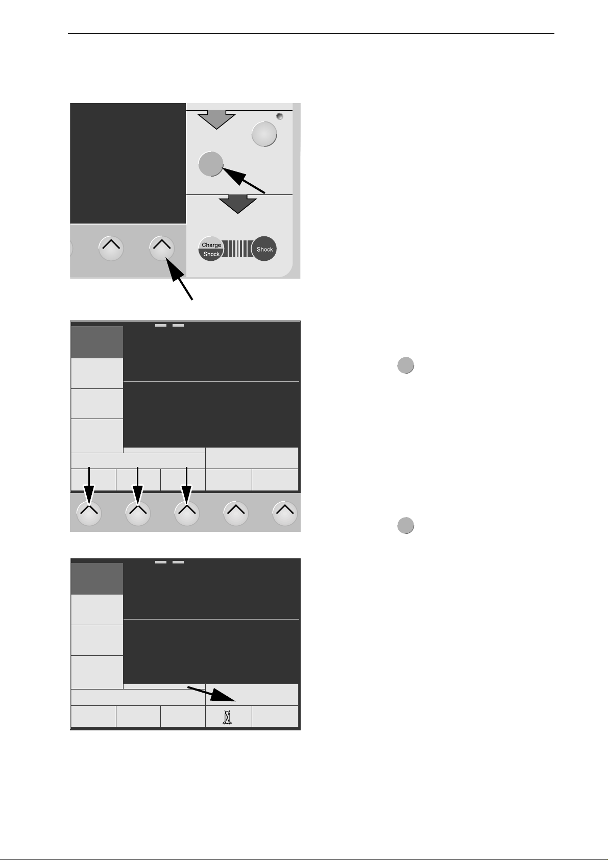
Figure 3-9. Buttons to activate the manual mode
0
ECG
Paddle
Electrode
15.07.1998 09:05:00
160 / 40
bpm
0 0 ENTER
semiautom.
0
Figure 3-10. Buttons for entry of the password
ECG
ECG
Paddle
15.07.1998 09:05:00
160 / 40
bpm
etCO2
SpO2
QRSPulse
Tone
OFF
Next
Menu
manual
0
Figure 3-11. Defibrillator set up for manual
operation
How to toggle the defibrillator from
semiautomatic to manual operation
Depending on their setup, semiautomatic defibril-
lators can be switched to manual control. The
defibrillator can be set up for four different modes
of operation:
−
semiautom./button (switching to manual mode
by activating button)
−
semiautom./password (switching to manual
mode by activating button and entering pass-
word)
−
semiautomatic (manual control not possible)
−
manual (only manual control possible)
Operating Mode "semiautomatic/button"
•
To activate the manual mode, simultaneously
press
F5
and
Analyse
(Figure 3-9).
When switched on again, the defibrillator will
reactivate the operating mode selected in the setup
menu.
Date and time of the change of operating modes is
stored in the event memory.
Operating Mode "semiautomatic/password"
•
To activate the manual mode, simultaneously
press
F5
and
Analyse
(Figure 3-9).
The screen for entry of the password appears
(Figure 3-10).
•
Enter the password (3-digit number) with F1,
F2, F3. The factory-set password is 111 (also
refer to chapter 13, section "Password").
When switched on again, the defibrillator will
reactivate the operating mode selected in the setup
menu.
Date and time of the change of operating modes is
stored in the event memory (chapter 11 "Memories
of the Marquette Responder® 3000").
If you wish to return to the semiautomatic mode,
you will have to turn the device off and on again.

Manual Defibrillation / Non-Synchronized Defibrillation
18 Marquette Responder® 3000 227 490 02-C
4 Manual Defibrillation
4.1 Defibrillator Application Guidelines
Observe the following guidelines to ensure
successful and safe defibrillation. Otherwise the
lives of the patient, the user and bystanders are in
danger.
Warning
-
Defibrillating a patient with normal hea rt
rhythm may induce ventricular fibrillation.
-
Position the patient flat on a hard surface
where he is electrically insulated. The patient
must not be allowed to come into contact with
metal parts, e.g., bed or litter, to prevent un-
wanted pathways for the defibrilla tion current
which may endanger the assistants. For the
same reason, do not position the patient on
wet ground (rain, accident in swimming pool).
Do not allow the defibrillation electrodes to
come into contact with other electrodes or
metal parts which are in contact with the pa-
tient.
The patient's chest must be dry, because
moisture can cause unwanted pathways for
the defibrillation current.
After use of flammable skin cleansing agents,
wait until they have completely dried.
-
The operator and all assistants must be briefed
regarding the preparations for and execution
of defibrillation.
All tasks must be clearly assigned .
Immediately prior to the shock
- interrupt heart massage and artificial
respiration,
- disconnect tube connections, and
- warn bystanders.
-
Ensure that no conductive connection between
the patient and bystanders exists during defi-
brillation.
-
Before delivering the shock, verify that the
charged and selected energies are the same.
-
Shock Hazard — Always switch off the device
before exchanging the defibrillation elec-
trodes.
-
Pacemaker Patients — Defibrillating a patient
with an implanted pacemaker is likely to im-
pair the pacemaker function or cause damage
to the pacemaker.
For this reason
- select the smallest energy level possible for
the application,
- do not apply the defibrillation paddles in the
vicinity of the pacemaker electrodes,
- have an external pacemaker at hand,
- check the implanted pacemaker for proper
functioning as soon as possible after the
shock.
Caution
-
Equipment Damage — Disconnect transduc-
ers and devices that are not defibrillation-
proof from the patient before delivering the
shock.
-
Equipment Damage — Do not defibrillate the
patient with a second defibrillator, while def i-
brillation electrodes (paddles, pads) of the first
device are applied.
If the use of a second defibrillator is inevita-
ble, disconnect the electrodes from the first
device or remove them from the patient.
Manual Defibrillation / Non-Synchronized Defibrillation
227 490 02-C Marquette Responder® 3000 19
Figure 4-1. Removing the paddles
ECG
Paddle
15.07.1999 09:05:00
160 / 40
bpm
Next
Menu
manual
0
200 J
ECG
SpO2
etCO2
QRSPulse
Tone
OFF
b ca
Figure 4-2. Power-up screen (paddles con-
nected)
a ECG signal acquired via
"Paddle"
b manual mode
c selected energy
SHOCK
3
STERNUM
SHOCK
3
CHARGE
2
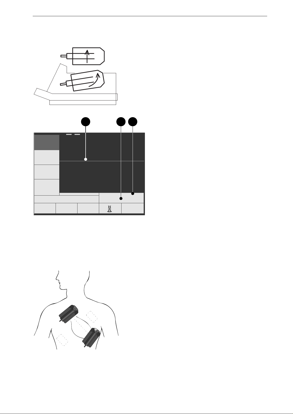
APEX
Figure 4-3. Paddle application points (dashed
application points for pacemaker
patients)
4.2 Non-Synchronized Defibrilla-
tion
Using Paddles
•
Remove the paddles from their compartments
as shown in Figure 4-1.
•
Carefully dry the paddles and the handles in
particular, if they are wet.
•
Apply an ample amount of electrode cream to
the paddle surfaces.
•
Set the energy selector to "Autoseq" or to the
required energy level.
In the "Autoseq" position of the energy selector,
the defibrillator automatically sequences the preset
defibrillation energy levels. The level for the 3rd
shock is maintained for all subsequent defibrilla-
tions. When you set the energy selector again to
"Autoseq", the automatic charge sequence starts
over.
The factory set Autosequence energy levels are the
values recommended by AHA/ERC for ventricular
fibrillation and pulseless tachycardia.
1st shock with 200 J
2nd shock with 200 J
3rd and all subsequent shocks with 360 J.
•
Check that the selected energy is displayed (
c
,
Figure 4-2).
•
Apply the paddles on the patient's thorax such
that the greatest possible amount of energy
flows through the myocardium. The imaginary
line connecting the paddle centers should be
identical with the cardiac median line (Figure
4-3).
•
Press the paddles firmly onto the thorax (the
ECG appears on the monitor screen).
•
Do not touch the patient any more and warn all
those present.
Manual Defibrillation / Non-synchronized Defibrillation
20 Marquette Responder® 3000 227 490 02-C
SHOCK
3
STERNUM
SHOCK
3
CHARGE
2
APEX
a
b
Figure 4-4. Buttons to initiate defibrillator
charging (a) and to trigger the shock
(a+b)
Warning
Risk of Skin Burns / Equipment Damage — Do
not apply the paddles over
-
sternum or clavicle,
-
nipples
-
implanted pacema ker or defibrillator devices.
Note
−
If you do not trigger the shock within 30 sec-
onds of charging, the energy will automatically
be discharged internally. You will then have to
recharge the defibrillator.
−
When the defibrillator is charged, you can
increase and decrease the energy level to any
value with the energy selector (without pressing
the "Charge" button again).
For an internal discharge of the stored energy,
set the energy selector to or to "Off".
•
Initiate energy storag e with the button on the
APEX paddle (
a
).
When the selected energy is stored,
−
the device emits an audio signal
−
the message "Energy available" appears,
−
the available energy is displayed (if the
available energy drops below a given level, the
defibrillator recharges automatically).
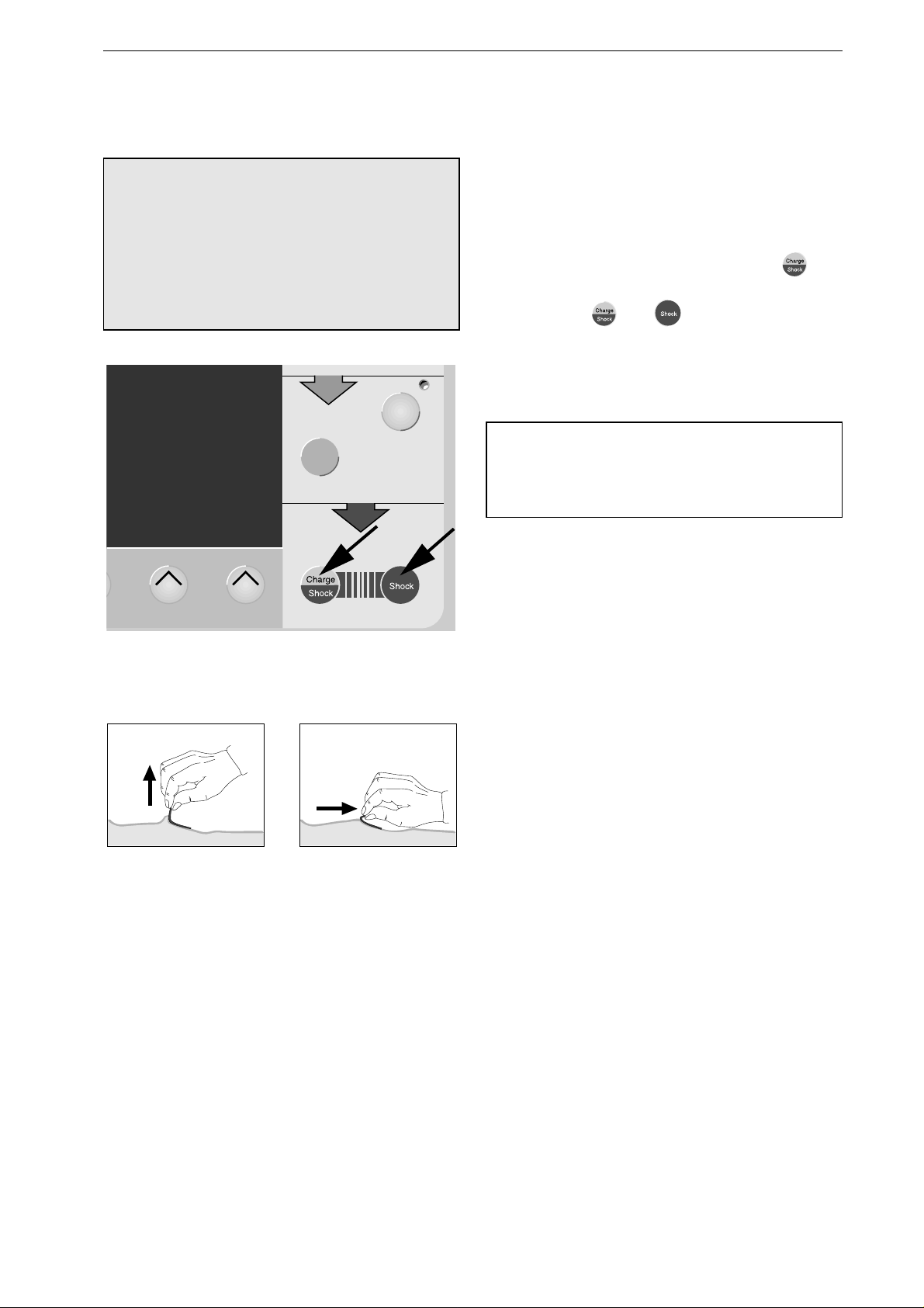
•
Now trigger the shock within 30 seconds. To do
so, simultaneously press the buttons
a
and
b
on
the paddles.
After the shock
−
the audio signal stops and the delivered energy
is displayed for approx. 6 seconds (in place of
the available energy),
−
the recorder prints a 14-second ECG strip (4
seconds before the shock, 5 seconds blanked,
10 seconds after the shock) (configurable); the
blanked period of time is indicated by a vertical
line on the recording;
−
the shock delivery is annotated on the stored
ECG (also refer to chapter 11 "Memories of the
Marquette Responder® 3000").
If the defibrillator cannot store the selected energy
so that selected and stored energy values differ, a
warning will be displayed. The defibrillation pulse
can be triggered all the same.
In this situation we recommend to check the
batteries first. If the batteries are intact, have the
defibrillator immediately repaired.
Manual Defibrillation / Non-Synchronized Defibrillation
227 490 02-C Marquette Responder® 3000 21
Shock Counter
The number of delivered shocks is indicated below
the energy value.
This counter is reset to 0 when you set the energy
selector to
.
The number of delivered shocks is also shown on
the recording strip (Figure 5-5, intervention report
d). This counter, however, counts all shocks since
the device was turned on and is reset to 0 only
when the device is turned OFF.
Ending Therapy
•
Once therapy has ended, set the energy selector
to
for continued monitoring of the patient.
•
If there is no need to monitor the patient, switch
off the defibrillator by setting the energy se-
lector to "Off".
•
Clean the paddles and the device as outlined in
chapter 18 "Cleaning, Maintenance".
Defibrillation of Children
Warning
Damage to Myocardium — Please note that chil-
dren require less energy for successful ventricular
defibrillation than adults. For the first defibrilla-
tion shock delivered to babies and small children,
select an energy of approx. 2 J/kg body weight.
For subsequent shocks, the energy may be in-
creased to 4 J/kg body weight.
Risk of Skin Burns — The full electrode m ust be
in contact with the skin surface (use the small
contact surface of the paddles / pads for children).
The paddles have two different contact surfaces; a
large one (can be removed) for the defibrillation of
adults and a smaller one for the defibrillation of
children.
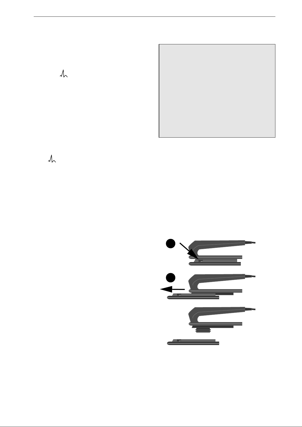
Remove the large contact surface for pediatric use:
•
Press on the lock button 1 (Figure 4-5).
•
Slide the contact surface 2 towards the front
and take it off the paddle.
•
When re-installing it, the large contact surface
must audibly click into place.
1
2
Figure 4-5. Removing the large contact surface
from the paddles
Manual Defibrillation / Non-synchronized Defibrillation
22 Marquette Responder® 3000 227 490 02-C
Danger
Shock Hazard — For defibrillation with dispos-
able adhesive electrodes, the paddles including
their leads must be replaced with the adapter cable
223 383 01. Switch off the defibrillator before
exchanging the lead. Also, the defibrillator must
be switched off when the adapter cable is con-
nected to the pads.
Figure 4-6. Connecting the lead
STERNUM
electrode and connector
APEX
electrode and connector
Figure 4-7. Defibrillation pad application points
(anterior - anterior)
Using Disposable Defibrillation Pads
−
Use pads before their expiration date.
−
Do
not
reuse the pads.
−
A pair of pads may remain attached to the
patient for up to 24 hours and withstands up to
50 shocks of 360 J each.
−
Use electrodes 919 202 94 for adults and
electrodes 919 202 95 for children.
−
Shave the application points; this improves
conductivity and makes removal of the pads
easier.
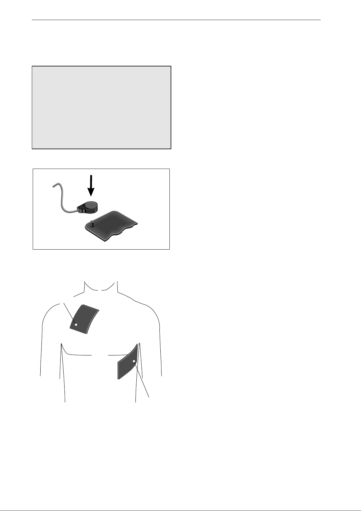
STERNUM: right sternal edge at the level of
the 2nd intercostal space,
APEX: left axillary line at the level of the 5th
intercostal space (Figure 4-7).
−
Place the pads on the patient such that the
connectors point to either side of the patient
and that the cables are not hindering patient
treatment.
−
The electrodes are pregelled; therefore, do not
use additional contact cream or gel.
−
Do not use pads, if the gel is dry.
•
Rub the patient's chest dry.
•
Press the connector of the lead on to the
electrode contact pin until you hear it click into
place (Figure 4-6).
•
Peel off the backing from each pad.
•
Press the pads carefully on the appropriate
sites, observing the APEX and STERNUM
labels (Figure 4-7).
Manual Defibrillation / Non-Synchronized Defibrillation
227 490 02-C Marquette Responder® 3000 23
Warning
Risk of Skin Burns / Equipment Damage — Do not
attach the pads over
-
sternum or clavicle
-
nipples
-
implanted pacema ker or defibrillator devices.
3
2
Analyse
Sync
Figure 4-8. Buttons to initiate defibrillator
charging and to trigger the shock
correct
wrong
Figure 4-9. Removing the pads
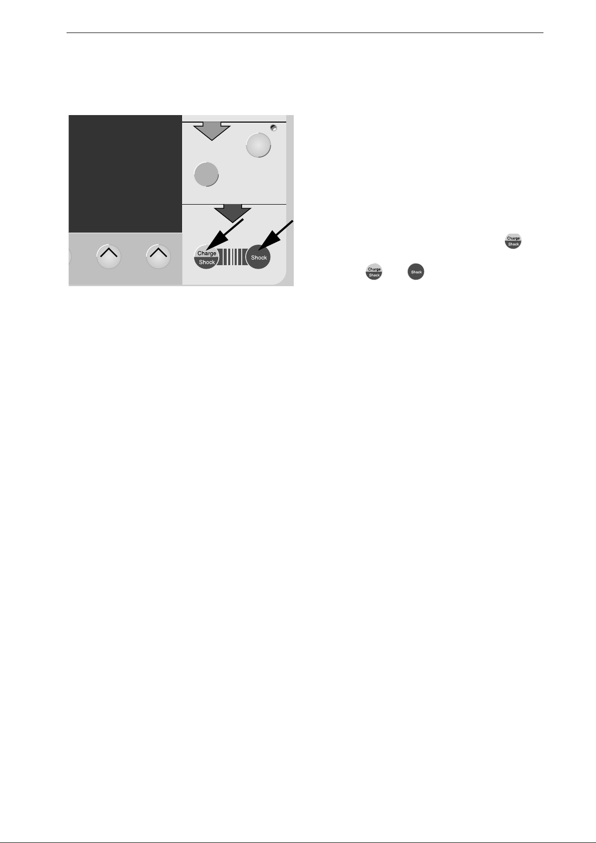
•
Before delivering the shock, check that the pads
are firmly seated.
•
Defibrillate the patient as described for
defibrillation with paddles (page 19).
Be sure to charge the defibrillator with
and
to deliver the shock by simultaneously pressing
the buttons
and
(Figure 4-8).
•
Carefully remove the electrodes after use
(Figure 4-9) and discard them immediately.
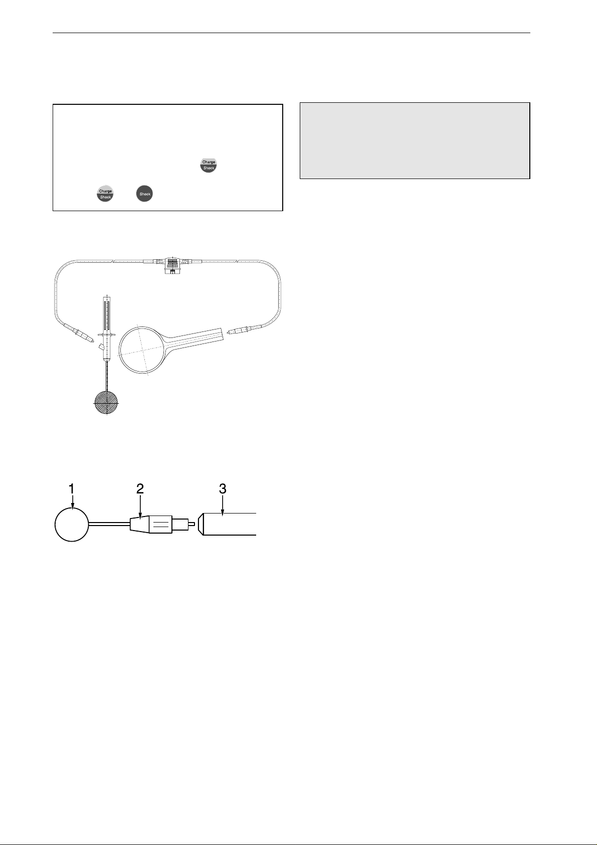
Note
Discard disposable pads immediately after use. Do
not reuse them.
Manual Defibrillation / Non-synchronized Defibrillation
24 Marquette Responder® 3000 227 490 02-C
Note
If you are using internal electrodes with the
Marquette Responder® 3000, defibrillator charg-
ing must be initiated with button and the
shock is delivered by simultaneously pressing
buttons and .
Figure 4-10. External counter electrode
Figure 4-11. Inserting the spoon electrode
Using Internal Defibrillation Elec-
trodes
Warning
Shock Hazard – Always switch off the device
before exchanging the defibrillation electrodes
and internal spoons.
Spoon-shaped electrodes are used for internal
defibrillation. Their contact surface must match
the dimensions of the heart. The spoons must make
full contact with the heart. There is a choice of 3
different spoon sizes. You can use either two
spoon electrodes or one spoon electrode and one
external counter electrode for defibrillation
(Figure 4-10, chapter 20 "Order Information").
Sterilize internal electrodes before each use
(chapter 18 "Cleaning, Maintenance").
Inserting the Spoon Electrode
•
Screw the counter nut
2
(Figure 4-11) onto the
electrode as far as it will go.
•
Screw the contact paddle
1
into the handle as
far as it will go, then bring it into the appropri-
ate position.
•
Now fix the contact paddle by screwing the
counter nut
2
tight against the handle
3
.
Manual Defibrillation / Non-Synchronized Defibrillation
227 490 02-C Marquette Responder® 3000 25
3
2
Analyse
Sync
Figure 4-12. Buttons to initiate defibrillator
charging and to trigger the shock
Defibrillating the Patient
With internal electrodes, it is not possible to select
a value above 50 Joules, because higher energies
may damage the myocardium. When you set the
energy selector to a value above 50 Joules, you
will be alerted by a message and defibrillator
charging will not proceed.
•
Defibrillate the patient as described for
defibrillation with paddles (page 19).
Be sure to charge the defibrillator with
and
to deliver the shock by simultaneously pressing
buttons
and (Figure 4-12).
Manual Defibrillation / Synchronized Defibrillation
26 Marquette Responder® 3000 227 490 02-C
Warning
False Triggering — Do not use a pacemaker ECG
for triggering, because the trigger pulses derived
from pacemaker ECGs may be incorrect and
synchronized delivery of the defibrillation shock
may not be possible.
Note
After each synchronized defibrillation, the device
reverts to the non-synchronized mode; the same
applies when the energy selector is set to .
4.3 Synchronized Defibrillation
(Cardioversion)
Some Basic Facts
For synchronized defibrillation (cardioversion) the
defibrillation shock is delivered in synchronization
with the heart action, as the heart is still working.
As a prerequisite, the patient's ECG signal must be
supplied to the defibrillator. After the attending
physician has given the "defibrillation command"
by pressing the appropriate buttons, the device will
wait for the next QRS complex to derive the
trigger signal for actual delivery of the shock.
The following electrodes can be used for cardio-
version:
−
paddles (+ separate ECG electrodes),
−
adhesive electrodes (pads), or
−
internal electrodes (+ separate ECG electrodes).
Indications
Examples
−
mitral stenosis
−
left ventricular hypertrophy (aortic stenosis,
hypertension)
−
impaired myocardiac function (ischemia, right
heart failure)
−
patients with atrial or ventricular arrhythmias,
hypotension and/or pulmonary edema.
If ventricular fibrillation develops, select the non-
synchronized mode for defibrillation, because it is
not possible to detect a QRS complex for
triggering in the presence of ventricular fibrilla-
tion.
Cardioversion with the Marquette Responder®
3000 is only possible in the manual mode.
We recommend acquiring the ECG with separate
ECG electrodes. However, you can also defibril-
late the patient with adhesive pads and pick up the
ECG via the pads.
Manual Defibrillation / Synchronized Defibrillation
227 490 02-C Marquette Responder® 3000 27
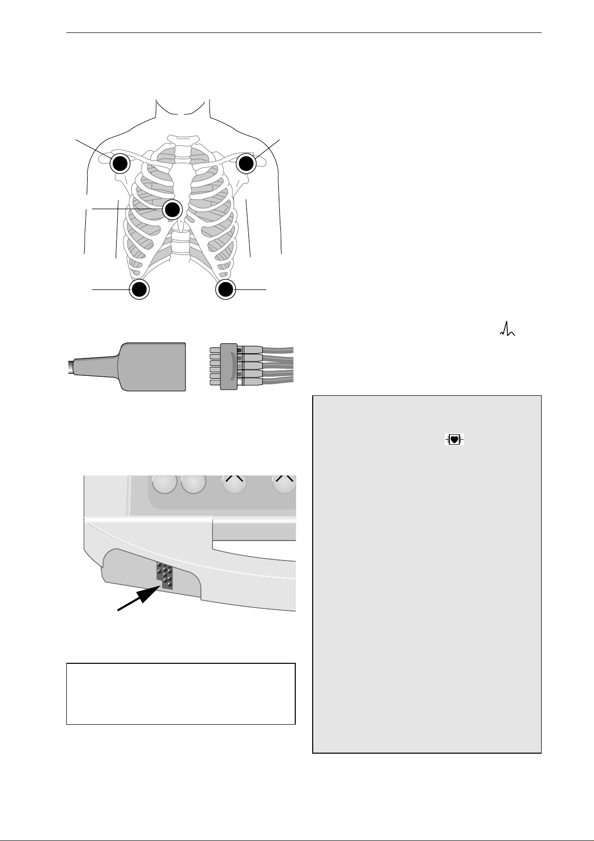
R L
C
N F
red
white
black
yellow
green
Figure 4-13. ECG electrode placement
Figure 4-14. Connecting the electrode leads to
the patient cable
Print Event
Figure 4-15. ECG signal input
Note
The 3-lead patient cable cannot be used with this
defibrillator.
ECG Acquisition via Separate ECG
Electrodes and Patient Cable
Use only silver/silver-chloride electrodes to
acquire the ECG signal. These electrodes prevent
polarization voltages which may be caused by the
defibrillation shock, resulting in an ECG trace on
the monitor screen or recording that simulates
cardiac arrest. The ECG can be picked up with 5
or with 10 electrodes (for ECG measurement,
however, 10 ECG electrodes are required (chapter
8)).
•
Apply the electrodes as shown in Figure 4-13.
•
Plug the block of leadwires (N, R, L, F, C1)
into the patient cable (Figure 4-14).
•
Connect the patient cable to the device (Figure
4-15).
•
Turn on the device (energy selector to ).
On the monitor screen you will now see the 3 ECG
leads selected in the setup menu (factory defaults:
leads I, II, III).
Warning
Sho c k H a zard / Equipment Da m ag e — All patient
signal inputs labeled with the symbol are
protected against damage resulting from defibril-
lation and electrocautery voltages. For th i s re a son,
patient safety and device protecti on are en sur ed
during defibrillation and HF surgery.
Nevertheless, extreme care should be exercised when
electrosurgery devices are used on a patient who is
connected to other devices. As a general rule, a
minimum distance of 15 cm between the ECG and
electrosurgery electrodes should be maintained. If
this is not ensured, temporarily disconnect the elec-
trodes and transducer l eads w hile usi ng the el ectro-
surgery device.
Great care must be exercised to prevent that conduc-
tive parts (connectors, electrodes, transducers) con-
nected to the isolated patient signal input come in
contact with other grounded conductive parts, as this
could bridge the patient 's i solat ion an d cancel th e
protection provided by the isol ated inpu t. It is par-
ticularly important that the neutral electrode does
not come in contact with ground.
 Loading...