


CardioServ

CardioServ
Operator’s Manual
Version 4.1
227 446 32 GA(e) Revision D

2 CardioServ V4.1 227 446 32-D
The product CardioServ bears the marking
-0366
indicating its conformity with the provisions of the Council
Directive 93/42/EEC concerning medical devices and fulfills
the essential requirements of Annex I of this directive.
The product complies with the electromagnetic immunity
requirements of standard IEC 60601-1-2/EN 60601-1-2
“Electromagnetic Compatibility – Medical Electrical Equip-
ment”.
The device is in radio-interference protection class B in
accordance with CISPR11/EN 55011.
The CE marking covers only the accessories listed in section
“Order Information and Accessories”.
This manual describes CardioServ with all options included
and reflects software version 4.1.
© Marquette Hellige GmbH 1999
Postfach 600265
D-79032 Freiburg
Germany
Telephone +49 7 61 45 43-0
Revision History
This document is subject to the Marquette Hellige change order system. The revision code, a letter that follows the document
part number, changes with every update of the manual. The initial version of the manual is without revision code.
Part No./Revision Code Date Comment
227 446 32 29 April 1997 Initial Release
227 446 32-A 14 May 1997 SW version 4.1
227 446 32-B 1 July 1997 ECO 202 998
227 446 32-C 9 July 1998 ECO 060 477
227 446 32-D 6 August 1999 ECO 062 982

227 446 32-D CardioServ V4.1 3
Contents
1. Introduction to CardioServ
2. Controls and Indicators
3. Setup and Performance Test
4. Non-Synchronized Defibrillation
5 Cardioversion (Synchronized Defibrillation)
6. Displaying and Monitoring the ECG
7. The Memories of CardioServ
8. Recording
9. Oxygen Saturation SpO
2
10. Pacing
11. Configuring the Defibrillator Settings
12. Error Indications and Messages
13. Cleaning and Maintenance
14. Technical Specifications
15. Order Information and Accessories
Index

4 CardioServ V4.1 227 446 32-D
General Information
General Information
* This manual is an integral part of the instrument and
describes its normal use. It should always be kept close to
the equipment. Observance of the manual is a prerequi-
site for proper instrument performance and correct
operation and ensures patient and operator safety.
* The symbol
denotes: Refer to Operator’s Manual!
It serves as an indicator for important facts to be noted
when operating the instrument.
* Information which refers only to certain versions of the
instrument is accompanied by the part number(s) of the
instrument(s) concerned. The part number is given on
the instrument nameplate.
* Patient safety, specified measuring accuracy, and interfer-
ence-free operation can be guaranteed only if original
Marquette Hellige devices are interconnected (e.g. basic
units and plug-in modules).
* Only use accessories which are listed in this manual or
which have been tested in combination with the device
(e.g. patient cables, electrodes, transducers, sensors,
consumables, etc.). If you use accessories or consumables
from other manufacturers, Marquette Hellige does not
guarantee safe operation or functioning of the device.
* The warranty does not cover damage resulting from the
use of accessories and consumables from other manufac-
turers.
* Marquette Hellige considers itself responsible for the
effects on safety, reliability, and performance of the
equipment, only if
– assembly operations, extensions, readjustments,
modifications, or repairs are carried out by
Marquette Hellige or by persons authorized by
Marquette Hellige
– the instrument is used in accordance with the
instructions for use.
* All publications are in conformity with the instrument
specifications and IEC publications on safety of electro-
medical equipment valid at the time of printing. All
rights are reserved for instruments, circuits, techniques,
software programs and names appearing in the manual.
* On request Marquette Hellige will provide a service
manual.
* The Marquette Hellige quality management system
complies with the standards DIN EN ISO 9001 and
EN 46001.

Introduction to CardioServ
227 446 32-D CardioServ V4.1 5
1. Introduction to CardioServ
This section describes
– The capabilities and applications of the CardioServ
defibrillator
– points to note when operating CardioServ
– general points to note when handling a defibrillator
Introduction to CardioServ
6 CardioServ V4.1 227 446 32-D
1.1 General Information
CardioServ is a light-weight, portable defibrillator with ECG
monitor and built-in recorder.
The device is designed for external and internal defibrillation.
It can be used both for semi-automatic and for manual defi-
brillation. Furthermore CardioServ is capable of monitoring
the heart rate with adjustable alarm limits.
CardioServ can be expanded with a transcutaneous pacemaker
and/or SpO
2
measuring system which also monitors the
measured SpO
2
values.
The device is easy and convenient to operate. Three operating
steps are sufficient to deliver the defibrillation shock. The
display can be turned 180° to allow the user to view the
information when the device is standing upright.
Defibrillation can be performed with standard defibrillation
paddles, defibrillation pads and internal electrodes.
In addition to line power operation, the defibrillator operates
on battery power from a slot-in rechargeable battery, and on
12-Volt power supplied from an emergency vehicle.
Dan
g
er
CardioServ is a high-voltage electrotherapy unit
which should be handled only by specially trained
personnel. Even though the defibrillator is
equipped with various safety features, such as
internal safety discharging, its operation by
unqualified staff could be hazardous to the
patient, the operator, and any assisting personnel.
☞
The user instructions given in this manual refer to a
CardioServ unit equipped with pacemaker and
SpO
2
measuring system.
Introduction to CardioServ
227 446 32-D CardioServ V4.1 7
CardioServ comes with three memories whose contents can
be documented individually:
– text memory (code summary documentation)
– event memory (16-s ECG)
– trend memory (trend plots of HR, SpO
2
, 45 min,
9 hours)
The built-in recorder is initiated automatically or manually.
Extensive safety precautions have been taken to protect the
patient and the user from inadvertent delivery of defibrillation
shocks.
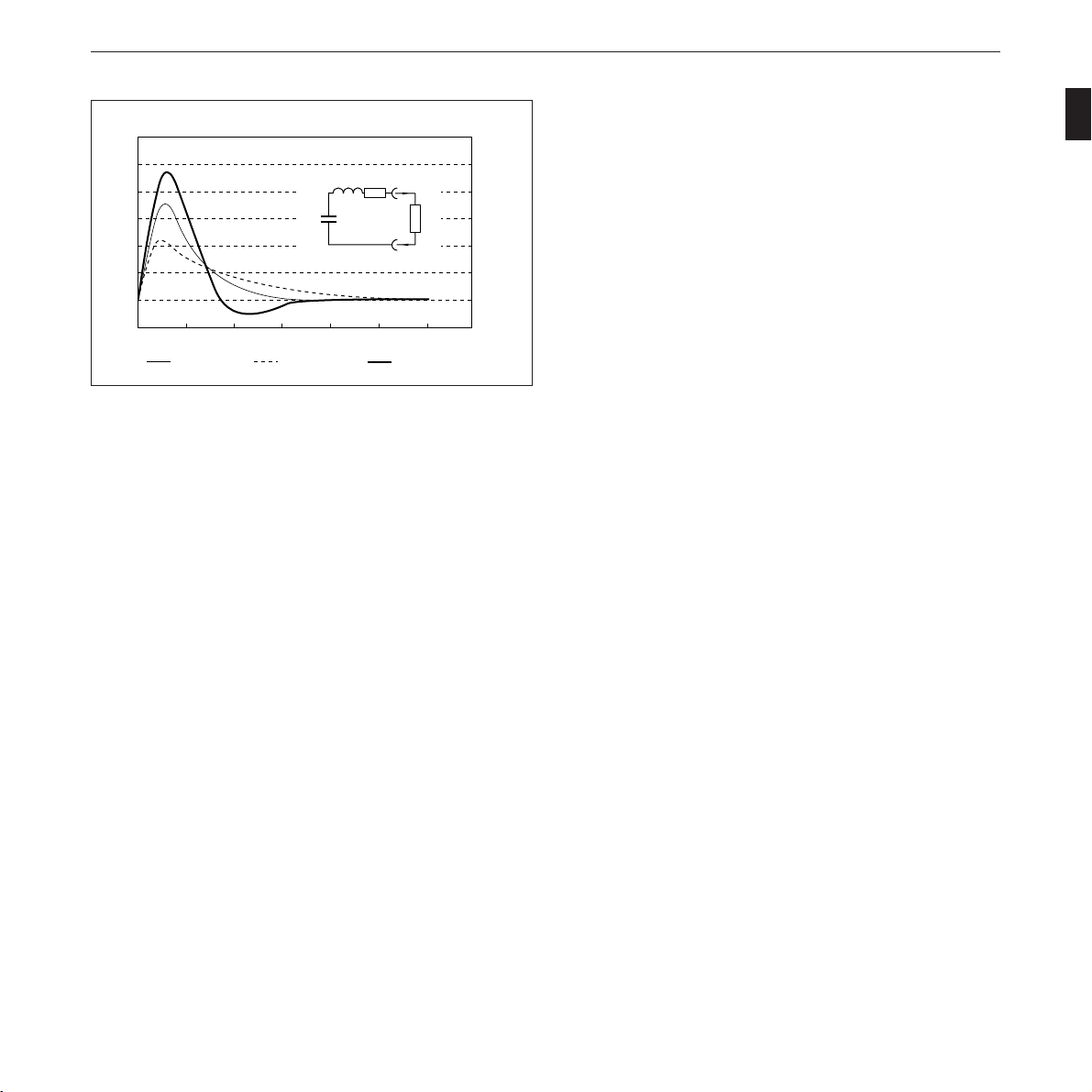
The current-discharge curve corresponds to an approximate
sinusoidal halfwave with aperiodic decay. Figure 1-1 shows
the discharge curve for various external resistances.
Figure 1-1. CardioServ current-discharge curve (360 J)
120
100
80
60
40
20
0
-20
I/A
0 2 4 6 8 10 12
t/ms
14
Ra = 50 Ohm Ra = 100 Ohm Ra = 25 Ohm
L = 26 mH
R = 6,5 Ω
t
R
a
C = 32 µF
U
c
I
Introduction to CardioServ
8 CardioServ V4.1 227 446 32-D
1.2 For your Safety
The safety information given below is divided into the catego-
ries “Danger”, “Warning” and “Caution”.
Dan
g
er
indicates an imminently hazardous situation
which, if not avoided, will result in death or
serious injury.
Warnin
g
indicates a potentially hazardous situation which,
if not avoided, could result in death or serious
injury.
Caution
indicates a potentially hazardous situation which,
if not avoided, may result in minor or moderate
injury and/or damage to the equipment.
☞
provides application tips or other useful information
to assure that you get the most from your equipment.
☞
CardioServ is designed to comply with IEC 60601/
EN60601 requirements. It is Class I equipment and
has an internal power source.
Warning
CardioServ operates on line voltages between 95
and 240 Volts, 49 to 65 Hz. The mains plug
must be connected to an appropriate power supply
with a non-fused earthed wire. The use of exten-
sion cords is not permitted.
Warning
Before putting the device into operation, visually
check all connecting cables and electrodes for signs
of damage. Damaged cables and electrodes must
be replaced immediately, before use.
Warning
When disconnecting the device from the power
line, first remove the plug from the wall outlet.
Warning
Disconnect the device from the power line and
operate it on battery power, if the integrity of the
protective earth conductor is in doubt.
Caution
Set up the device in a location which affords
sufficient ventilation. The ventilation openings of
the device must not be obstructed. The ambient
conditions specified in the “Technical Specifica-
tions” section must be ensured at all times.
Introduction to CardioServ
227 446 32-D CardioServ V4.1 9
Warnin
g
Devices intended for emergency application must
not be exposed to low temperatures during storage
and transport to avoid moisture condensation at
the application site. Wait until all moisture has
vaporized before using the device. Avoid using the
defibrillator under conditions where prolonged
exposure to or excessive contact with moisture can
occur.
Dan
g
er
Before putting the defibrillator into operation,
make sure that the paddles and all connection
cables are dry.
Warnin
g
CardioServ is an emergency device and must be
ready for operation at any time. For this reason,
the defibrillator battery must always be charged.
This can be achieved by leaving the defibrillator
connected to the power line when it is not needed
in an environment where only battery operation
is possible.
Dan
g
er
Possible explosion hazard if used in the presence
of concentrated oxygen.
Warnin
g
CardioServ is suitable for application in a humid
environment provided the regulations concerning
drip-proof equipment of IEC 60601 are strictly
observed. However, avoid defibrillation in a very
moist or wet environment, unless absolutely
necessary.
Caution
Use only the original Marquette Hellige batteries,
as these are designed for an extended temperature
range.
Warning
Magnetic and electrical fields are capable of
interfering with the proper performance of the
device. For this reason make sure that all external
devices operated in the vicinity of the defibrillator
comply with the relevant EMC requirements. X-
ray equipment, MRI devices and radio systems
are a possible source of interference as they may
emit higher levels of electromagnetic radiation.
☞
The defibrillator is designed for intracardiac appli-
cation.
Warning
Devices may be connected to other devices or to
parts of systems only when it has been made
certain that there is no danger to the patient, the
operators, or the environment as a result. In those
instances where there is any element of doubt
concerning the safety of connected devices, the
user must contact the manufacturers concerned or
other informed experts as to whether there is any
possible danger to the patient, the operator, or the
environment as a result of the proposed combina-
tion of devices. Standards IEC 60601-1-1/
EN 60601-1-1 must be complied with in all
cases.
☞
Set up the device so that the operator has a clear,
unobstructed view of the front panel.
Warning
Liquids must not be allowed to enter the device.
Devices into which liquids have penetrated must
be immediately cleaned and checked by a service
technician.
Introduction to CardioServ
10 CardioServ V4.1 227 446 32-D
☞
CardioServ also operates on line power when the
battery is depleted or missing.
Caution
At the end of its service life, CardioServ and its
accessories must be disposed of in compliance with
the special waste control regulations for electronic
parts. If you have any questions in this matter,
please contact Marquette Hellige GmbH.
Warning
Dispose of the packaging material, observing the
applicable waste-control regulations and keeping
it out of children’s reach.
Literature
Medical Device Directive
EN 60601-1/1990 + A 1: 1993 + A2: 1995: Medical electrical
equipment. General requirements for safety
EN 60601-1-1/9.1994 + A1 12/1995: General requirements
for safety. Requirements for the safety of medical electrical
systems.
IEC Publication 513/1994: Fundamental aspects of safety
standards for medical equipment.
ROY, O.Z.: Summary of cardiac fibrillation thresholds for
60-Hz currents and voltages applied directly to the heart.
Med. & Biol. Engn. & Computing 18: 657...659 (1980).
Dan
g
er
Use only the original Marquette Hellige patient
cables. Do not connect other signal sources to the
cables.
Caution
Patient signal inputs labelled with the
symbol are protected against damage resulting
from defibrillation and electrocautery voltages.
Nevertheless extreme care must be taken when
devices which are directly connected to the patient
remain applied during electrocautery or defibril-
lation. The distance between ECG electrodes
should be at least 15 cm. If in doubt, disconnect
the patient cable from the device while applying
the defibrillation pulse or performing
electrocautery.
Warnin
g
For defibrillation of children use only the special
clip-on electrodes for children listed in section 15
“Order Information and Accessories”.
Warnin
g
The full responsibility for the use of accessories
from other manufacturers lies with the user.
Caution
Check the device performance at regular intervals
(once a month), strictly following the instructions
given in section 3.2. Do not select high energy
levels for test discharges with defibrillation elec-
trodes shorted together.
Caution
For each defibrillation, verify that the selected
and the displayed/charged energy are identical.
Introduction to CardioServ
227 446 32-D CardioServ V4.1 11
General points to note when handling a defibrillator
Warnin
g
Electromedical equipment such as the CardioServ
defibrillator must only be handled by persons who
are trained in the use of such equipment and are
capable of applying it properly.
Warnin
g
Before using the equipment, the operator must
ascertain that it is in correct working order and
operating condition.
Dan
g
er
The defibrillator paddles must be clean and dry.
☞
The person carrying out the defibrillation should
have at least one assistant.
Warnin
g
The operator must be trained in the use of the
defibrillator.
Warnin
g
All assistants must be briefed regarding the
preparations for and execution of defibrillation.
Warnin
g
All tasks must be assigned clearly.
Dan
g
er
Defibrillating a patient with normal heart
rhythm may induce ventricular fibrillation.
Caution
Position the patient flat on a hard, dry surface
where the patient is electrically insulated. The
patient must not be allowed to come into contact
with metal parts, e.g., bed or litter, in order to
prevent unwanted pathways for the defibrillation
current which endanger the assistants. For the
same reason, do not place the patient on wet
ground (rain, accident in swimming pool).
☞
Have a pacemaker at hand, if possible.
☞
Should cardiac arrest occur or be imminent during
preparations for defibrillation, administer heart
massage and artificial respiration (CPR).
Danger
Do not allow the defibrillator paddles to come
into contact with other electrodes or metal parts
which are in contact with the patient.
Caution
Transducers and instruments that are not defi-
brillation-proof must be disconnected from the
patient.
Danger
Interrupt heart massage and artificial respiration
immediately before triggering the shock.
Caution
Immediately before triggering the shock discon-
nect tubes and have assistants step back.
Introduction to CardioServ
12 CardioServ V4.1 227 446 32-D
Caution
The patient’s chest must be dry, as moisture causes
unwanted pathways for the defibrillation current.
Therefore, when using flammable skin cleansing
agents, wait until they have completely dried.
Dan
g
er
Possible explosion hazard if used in the presence
of concentrated oxygen, flammable substances
(gasoline) or anesthetic agents. Oxygenation in
the vicinity of the defibrillation paddles must be
strictly avoided; if necessary, interrupt oxygen
supply while defibrillating the patient.
Warnin
g
To prevent sparking
– the electrodes should make full contact with
the body
– the electrodes should be pressed firmly onto
the thorax.
Caution
When defibrillating children it is especially
important to verify that the paddles make full
contact with the body surface. This is to be ob-
served also when using the clip-on electrodes for
children (Part No. 303 439 95).
Warning
Defibrillating a patient who has an implanted
pacemaker is likely to impair the pacemaker
function or cause damage to the pacemaker.
Therefore, the following should be observed:
– Select the smallest energy level possible for the
application.
– Do not apply the defibrillation paddles in the
vicinity of the pacemaker electrodes.
– The availability of an external pacemaker is
of utmost importance in this case.
– After the defibrillation the working order of
the implanted pacemaker should be checked
immediately.
Warning
Also be aware that children require less energy for
a successful defibrillation than adults. For the
first defibrillation pulse delivered to babies and
toddlers, select an energy level of 2 joules/kg body
weight. For subsequent shocks, increase the energy
up to 4 joules/kg.

Controls and Indicators
227 446 32-D CardioServ V4.1 13
2. Controls and Indicators
This section describes the CardioServ operating controls and
indicators and explains their function.
When operating elements in this manual are identified with
a reference number in parentheses, this number refers to
Figure 2-1 in this section.
You will also find an explanation of all signs and symbols
used on the CardioServ defibrillator.
Controls and Indicators
14 CardioServ V4.1 227 446 32-D
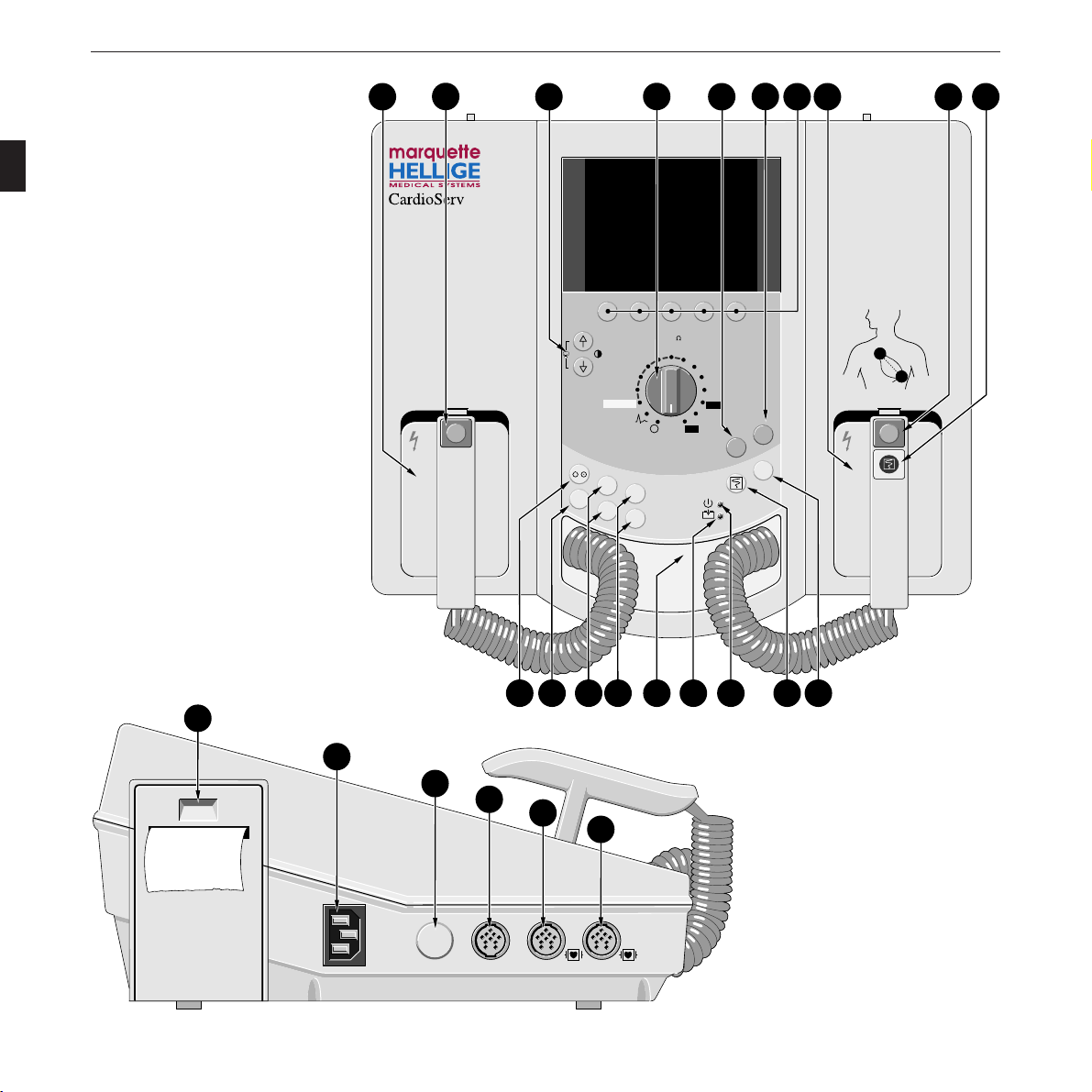
Figure 2-1. Controls and indicators of CardioServ VF
EKG
SpO
2
Option
19
20
21
23
24
22
3
2
3
Charge
-
+
2
2
5
7
10
20
30
50
100
150
300
J (50 )
200
360
Charge
Shock
Shock
Sync
APEX
Apply electrode cream to both paddles
Press charge button on apex paddle
(on the device, when using adhesive
or internal electrodes)
Press buttons on both paddles simul-
taneously (on the device, when using
adhesive or internal electrodes)
Charge defibrillator
Deliver shock3
2
1 Select energy
P
a
c
e
m
a
k
e
r
S
t
i
m
u
l
a
t
e
u
r
Dem
Fix
+
P/min
P/min
–
+
mA
mA
–
Shock
Charge
Shock
Autosequence
STERNUM
APEX
2
1418 17 16 15
13
11
10
12
1
13 8 975
4
6

Controls and Indicators
227 446 32-D CardioServ V4.1 15
1 Defibrillator paddles
2
3
Shock
button to trigger the defibrillation shock – together
with button (8)
3 keys to adjust the LCD contrast. Press both
keys simultaneously to obtain a screen copy.
4 Energy selector, on/off switch
5
Charge
Shock
key to charge the unit (manual mode) and to
trigger the defibrillation shock – together with key (6).
This key assumes the function of button (8) when
internal paddles or adhesive electrodes are used.
6
Shock
key to trigger the defibrillation shock – together
with key (5). This key assumes the function of button
(2) when internal paddles or adhesive electrodes are used.
7 Five selection keys F1 to F5 whose functions change
with the menu displayed. The respective key functions
are indicated by symbols or labels in the bottom line on
the LCD. From the main menu, that appears on power
up, you can access submenus which, in turn, allow the
selection of further options. The back function returns
you to the next higher menu level. The main menu
reappears automatically if you do not depress any of the
keys for about 30 seconds.
8
2
3
Charge
Shock
button to charge the unit (manual mode) and
trigger the defibrillation shock – together with button (2)
9 button to start and stop the recorder.
10
Sync
key to switch to the synchronized operating mode
(section 5 “Cardioversion”)
11 key to start and stop the recorder. This key assumes
the function of button (9) when internal paddles or
adhesive electrodes are used.
12 Green indicator is lit when the defibrillator operates
on line power.
13 Yellow indicator
-
+
is lit when the defibrillator battery
is being charged.
14 Connection for defibrillator paddles
(controls 15 to 18 only on models with pacemaker)
15 Keys
+
mA
mA
-
to adjust the pacer output
16 Keys
+
P/min
P/min
-
to adjust pacer rate
17 Pacing mode selection key
Dem
Fix
(demand/fixed rate)
18 Key to enable and disable the pacemaker
19 Aperture to open the paper compartment
20 Connector for power cord
21 Unassigned
22 1-Volt ECG output
23 Connector for SpO
2
sensor
24 Connector for patient cable (ECG signal input)
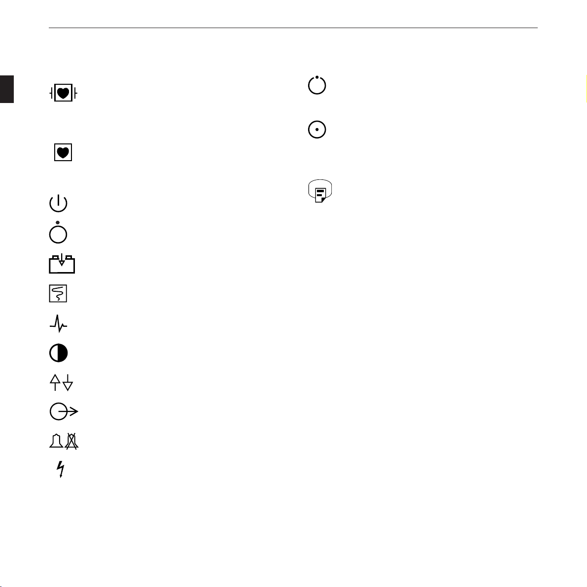
Controls and Indicators
16 CardioServ V4.1 227 446 32-D
Type CF equipment with highly insulated patient
connections, suitable for intracardiac application,
connections defibrillation-proof.
Type CF equipment with highly insulated patient
connections, suitable for intracardiac application,
connections not defibrillation-proof.
Standby mode (for line-power operation)
Power off
Battery charging
Recorder start
ECG signal
Contrast
Direction indicator
Signal output
Audible alarm on/off
High voltage
Standby or preparatory state only for a part of the
equipment
On, only for a part of the equipment
Refer to Operator’s Manual
Hardcopy of screen image
Explanation of the signs and symbols used on the defibrillator
-
+

Setting Up CardioServ and Testing Its Performance
227 446 32-D CardioServ V4.1 17
3. Setting Up CardioServ and
Testing Its Performance
In this section you will find information about
– putting CardioServ into operation
– connecting CardioServ to the 12-Volt power supply of
an ambulance vehicle
– customizing the CardioServ settings to suit your per-
sonal requirements
– testing the CardioServ performance before using it on a
patient
Setting Up CardioServ and Testing Its Performance
18 CardioServ V4.1 227 446 32-D
3.1 Setting Up CardioServ
CardioServ operates on:
– line power (95 to 240 V, 49 to 65 Hz)
– battery power (rechargeable batteries), i.e., independent
of the power line
– 12-Volt power supplied from the emergency vehicle
(with optional defibrillator mounting system)
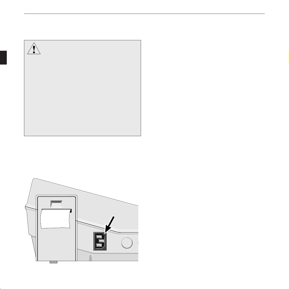
* Use the power cord to connect the defibrillator to the
power line (Figure 3-1).
Dan
g
er
The defibrillator is a high-voltage electrotherapy
device and must be handled by qualified person-
nel only. Improper use of this device can endanger
life. Do not fail to observe the information given
in this manual and only entrust the device to the
hands of trained persons.
Check the electrodes and their leads for signs of
damage every time before you use the defibrilla-
tor. In particular, make a close visual inspection
of the insulation. Replace internal electrodes or
the contact inserts when you detect signs of me-
chanical damage.
Figure 3-1. Power input
Setting Up CardioServ and Testing Its Performance
227 446 32-D CardioServ V4.1 19
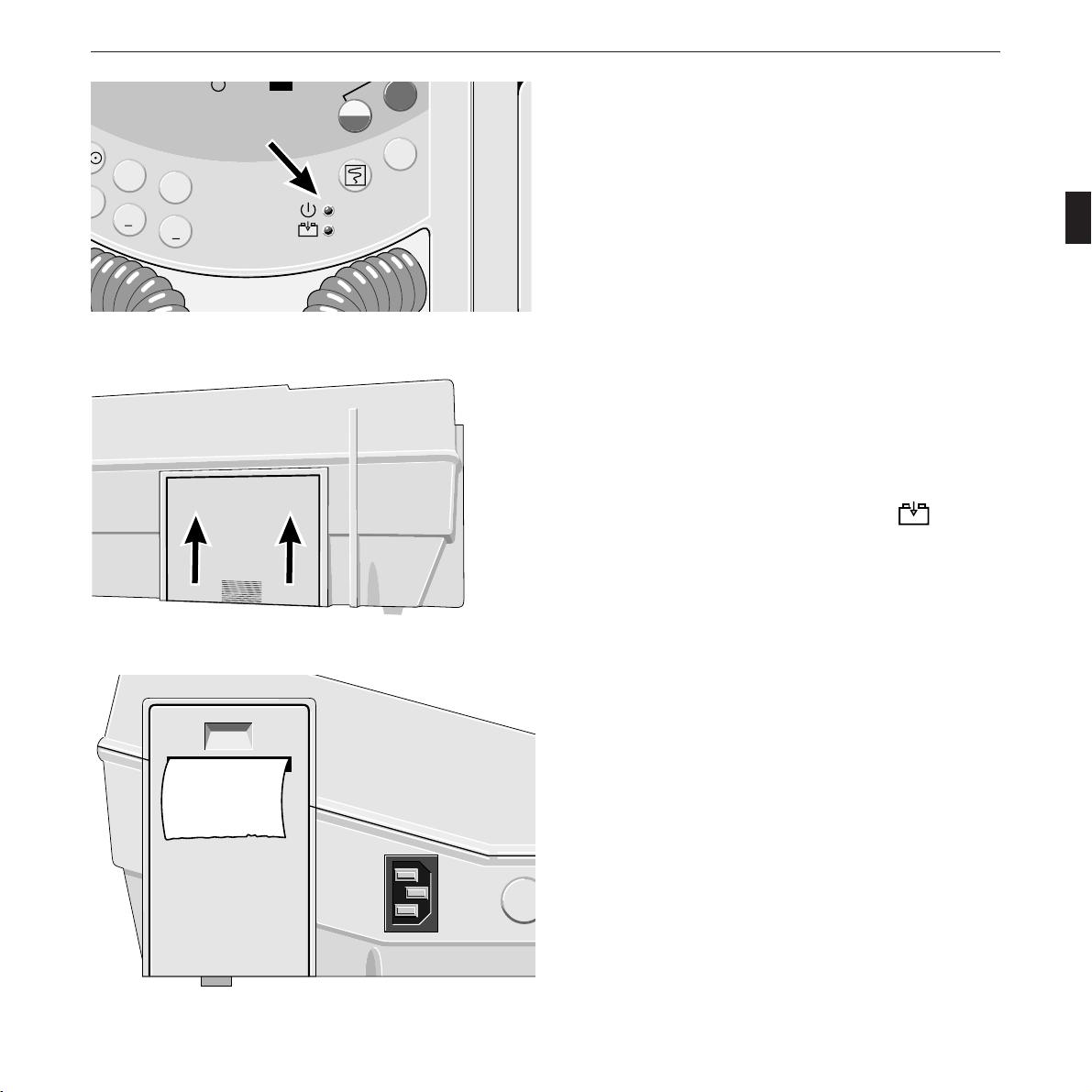
Figure 3-2. Green indicator (indicating that defibrillator is
supplied from the power line)
360
Charge
Shock
Shock
Sync
m
x
P/min
P/min
mA
mA
-
+
m
a
k
e
r
S
t
i
m
u
l
a
t
e
u
r
+
+
* Check that the green indicator is lit (Figure 3-2).
* Check that the battery is in place (Figure 3-3).
Pull back the catch on the underside of the device to remove
the battery. When inserting it, make sure that it clicks prop-
erly into place.
When a battery is inserted, the yellow indicator
-
+
starts
flashing as soon as the defibrillator is connected to the power
line (to indicate that the battery is charging). The battery is
fully charged after 16 hours and the indicator is continuously
lit.
* Check that the supply of chart paper is sufficient (Figure
3-4). A stripe marks the last 3 meters of the roll.
Figure 3-3. Inserting the battery
Figure 3-4. Recording strip
Setting Up CardioServ and Testing Its Performance
20 CardioServ V4.1 227 446 32-D
Power Supply From Emergency Vehicles
A qualified technician can be called in to connect the
CardioServ to the 12-Volt supply of an emergency vehicle.
The following points must be noted:
– The negative terminal of the ambulance power supply
system must be connected to the ambulance chassis for
grounding.
– The positive lead of the ambulance power supply system
intended to supply the current must be protected with a
10-A fuse.
– Use only the defibrillator mounting system listed in
section 15 “Order Information and Accessories” or the
external charging unit, if your CardioServ has been
modified accordingly.
Check that the contacts for power supply from the
defibrillator mounting system on the underside of
CardioServ (next to battery) are clean. Do not damage
them in any way.
Important Information on Battery-Power Operation
Rechargeable batteries require special maintenance and con-
tinued checks to assure they function in emergency situations.
It is normal for batteries of this type to selfdischarge when not
in use.
The battery charges automatically when CardioServ is con-
nected to the power line (yellow indicator (13) flashes).
Warnin
g
A NiCd battery should not be charged while
located in direct sunlight, over a radiator, in cold
storage, or in other temperature extremes (not
below 5 °C). When the instrument is charging,
ambient temperatures exceeding 40 °C may
adversely affect battery capacity and life.
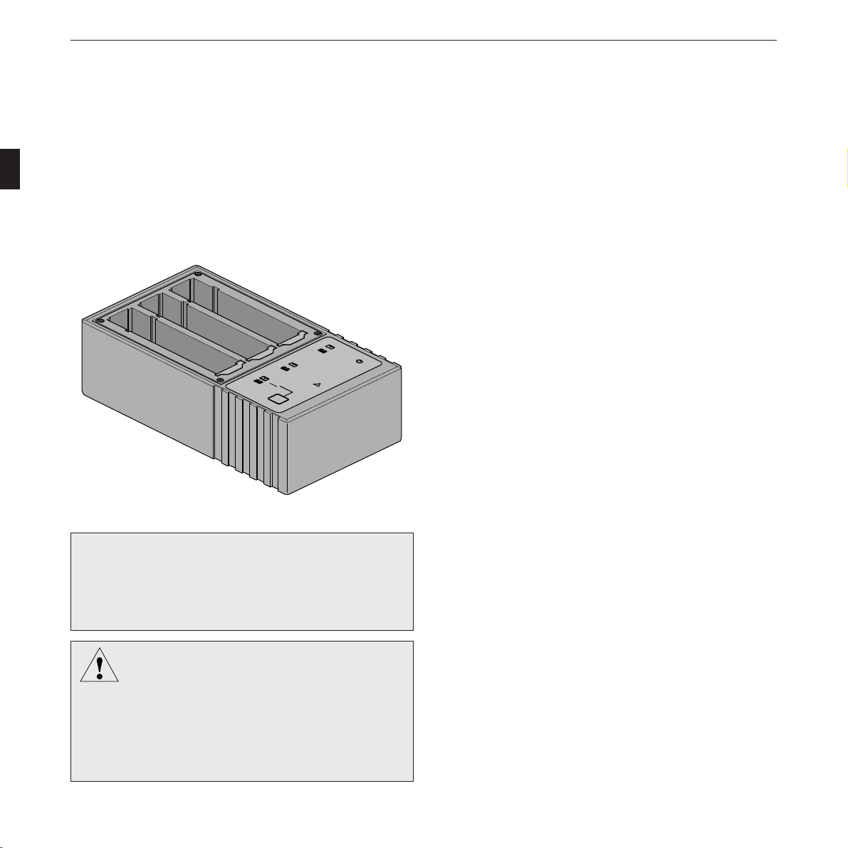
☞
We recommend our Accu Service Unit for optimal
care of the batteries. It prolongs the batteries’ service
life and guarantees their operational readiness at all
times.
T
e
s
t
T
e
s
t
S
ta
rt
>
9
5
%
>
8
0
%
<
8
0
%
-
+
-
+
-
+
Figure 3-5. Accu Service Unit
Setting Up CardioServ and Testing Its Performance
227 446 32-D CardioServ V4.1 21
In order to ensure its functioning as an emergency device, the
defibrillator should not be disconnected from the power line
for more than 48 hours.
A fully charged battery supplies power for 35 defibrillation
shocks of 360 joules or 2 hours of monitoring (or 1.2 hours of
monitoring if the CardioServ unit has pacemaker and SpO
2
option). It takes 16 hours to charge a depleted battery.
☞
Proceed as follows to test the battery charge level:
– Disconnect CardioServ from the power line.
– Trigger a test discharge of 360 joules (see
section 3.2 “Testing the Defibrillator Perform-
ance”).
– If you are not prompted to charge the battery,
the charge level should be sufficient for at least
5 more 360-joule shocks.
☞
Monthly battery maintenance and checks:
1. Disconnect CardioServ from the power line and
discharge fully charged battery in the monitoring
mode. To do so, set energy selector switch to ,
(SpO
2
sensor not connected) and wait until device
switches off.
2. Check how long it takes before battery is depleted.
If the time is less than 1.8 hours, the battery is too
old or improperly maintained and must be
replaced.
3. Recharge the battery. This will take 16 hours.
For easy, convenient care and maintenance of the
batteries, use our “Accu Service Unit”.
Inserting CardioServ In Its Softcase
* Open both zips on the CardioServ softcase.
* Undo the two Velcro strips on the front of the softcase.
* Open the Velcro flap located in front of the CardioServ
printer.
* Place the softcase on the small base, so that the softcase is
positioned as though you were carrying it.
* Disconnect the paddles on the CardioServ and remove
them.
* Hold all the opened up parts of the softcase to the side
and put the CardioServ into the softcase.
* Pull the softcase by the two Velcro strips on the black
base into position, ensuring that the feet of the
CardioServ are in the cut-out openings provided.
* Close the two front Velcro strips as well as the flap in
front of the printer at the side.
* Close the zips.
* If the individual cut-out openings for the external con-
nections, paddles or feet are not correctly positioned,
pull the material at this point into the right shape.
* Reconnect the paddles and put them back into the
CardioServ recesses.

Setting Up CardioServ and Testing Its Performance
22 CardioServ V4.1 227 446 32-D
Customizing the defibrillator settings
Further steps that can be taken while setting up the defibrilla-
tor include customizing the device functions. This allows you
to select defibrillator default settings which suit your personal
preferences. CardioServ saves these configured settings and
reactivates them automatically every time you switch the
defibrillator on. The following chart shows the factory settings
of all parameters and the optional adjustments.
Refer to section 11 “The Defaults Menu” for a detailed
explanation of how to customize the CardioServ, including
the language selection (available languages are English,
French, German, Italian, Portuguese, Russian, Spanish and
Swedish).
retemaraP noitpircseD gnitteSyrotcaF egnartnemtsujdA sgnittesdezimotsuC
stimiLRH stimilmralaRH 061/04 ffo003ot51ffo
ytivitisneS ezislangisGCE 1 Vm/mc2,1,5.
daeL 1 selddap+sdaeldradnatslla
.qesotuA slevelygrenegnicneuqesotua J063,J002,J002 ,J063,J003,J002,J051
OpS
2
stimiL stimilmrala ffo/09 ffo001ot51ffo
kcoL-C OpSdezinorhcnys-GCE
2
tnemerusaem ffo ffo/no
OpS
2
emiT.tnI OpS
2
emitnoitargetni s8 )dednemmocerton(s21,s8,s4
mralAliaFdaeL ffo s03/ffo
peeBSRQ ffo ffo/no
enoTmralA ffo ffo/no
tuotnirPmralA tratsredrocer.motua ffo ffo/no
tuotnirPkcohS tratsredrocer.motua no ffo/no
tuotnirP.tnoC tratslaunamnopupotsredrocer ffo ffo/no
rekamecaP etareslup MPB06 nim/P051ot51
yalpsiD lamron desrever/lamron
yalpsiD seerged0 seerged081/seerged0
emuloV slangisoiduallafoemulov duol wol/duol
retliFCA zH05 ffo/zH06/zH05
retliFelcsuM tcafitranoitomfonoitanimile no ffo/no
emiT/etaD
tamroFetaD YYYY:MM:DD YYYY:DD:MM/YYYY:MM:DD
egaugnaL namreG ,namreG,hcnerF,hsilgnE
,naissuR,eseugutroP,nailatI
hsidewS,hsinapS
resU )sretcarahc04(emanrotxeteerf
tluafedyrotcaF sgnittesyrotcafhsilbatseer ffo ffo/no
Table 1
Setting Up CardioServ and Testing Its Performance
227 446 32-D CardioServ V4.1 23
3.2 Testing the Defibrillator
Performance
On power up CardioServ runs an automatic selftest. Any
malfunctions identified during this test result in an error
message displayed on the LCD (refer to section 12 “Error
Indications and Messages”). As a further performance test a
trial defibrillation can be triggered.
The energy selector is used to switch CardioServ on and off.
Once you have become familiar with CardioServ you can thus
switch on the defibrillator and select the required energy in
one single operation.
* Set the energy selector to the position. No energy
will be stored in this position of the switch.
The defibrillator beeps and displays a checkered pattern
(LCD performance test). Next the main display appears
(Figure 3-7).
The “Paddle” message (b, Figure 3-7) indicates that no pa-
tient cable is connected and that the ECG signal is acquired
via the defib paddles. Upon connection of the patient cable
the selected ECG lead is displayed here. CardioServ is now
ready for operation.
2
5
7
10
20
30
50
100
150
300
J (50 Ω)
200
360
Charge
Shock
Shock
Sync
Autosequence
P
a
c
e
m
a
k
e
r
S
t
i
m
Figure 3-6. Switching on CardioServ
0
160 BPM
140 ECG
HR Alarm
Paddle
Next
Menu
FreezeSpO2ECG
a b
f
g
d
e
c
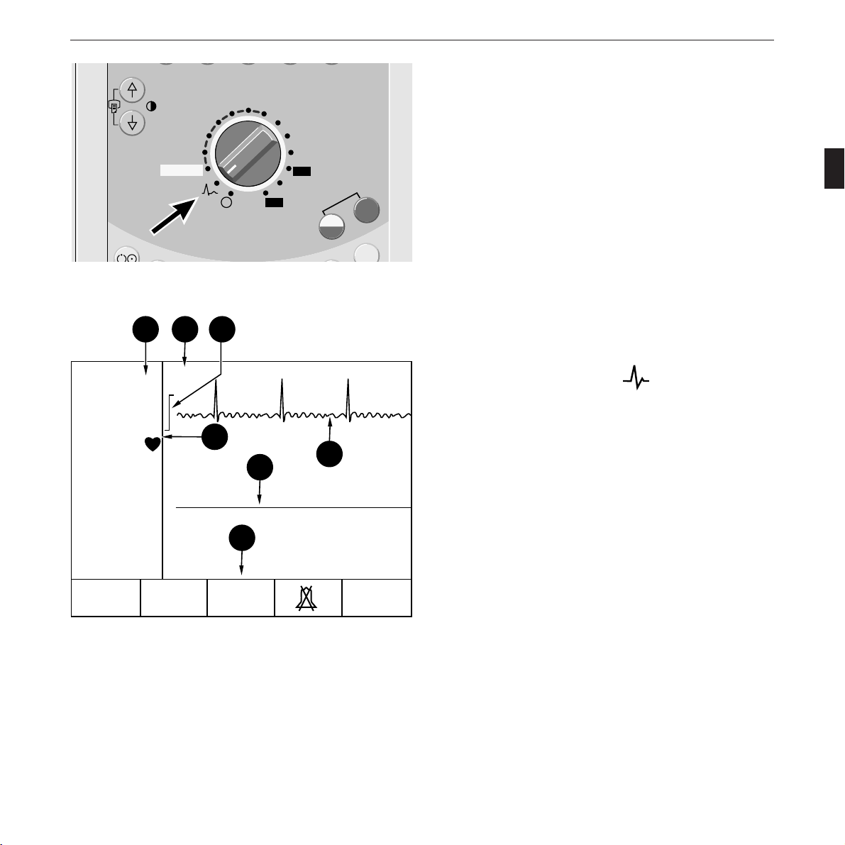
Figure 3-7. CardioServ main display
a heart/pulse-rate reading with alarm limits
b ECG signal source
c 1-mV calibration pulse
d alarm message, QRS blip
e signal trace, channel 1
f signal trace, channel 2
g menu
Setting Up CardioServ and Testing Its Performance
24 CardioServ V4.1 227 446 32-D
Test Discharge
A test discharge can be triggered to check the defibrillator
discharge circuit. For this test the stored energy is discharged
into the device via two contacts in the paddle compartments.
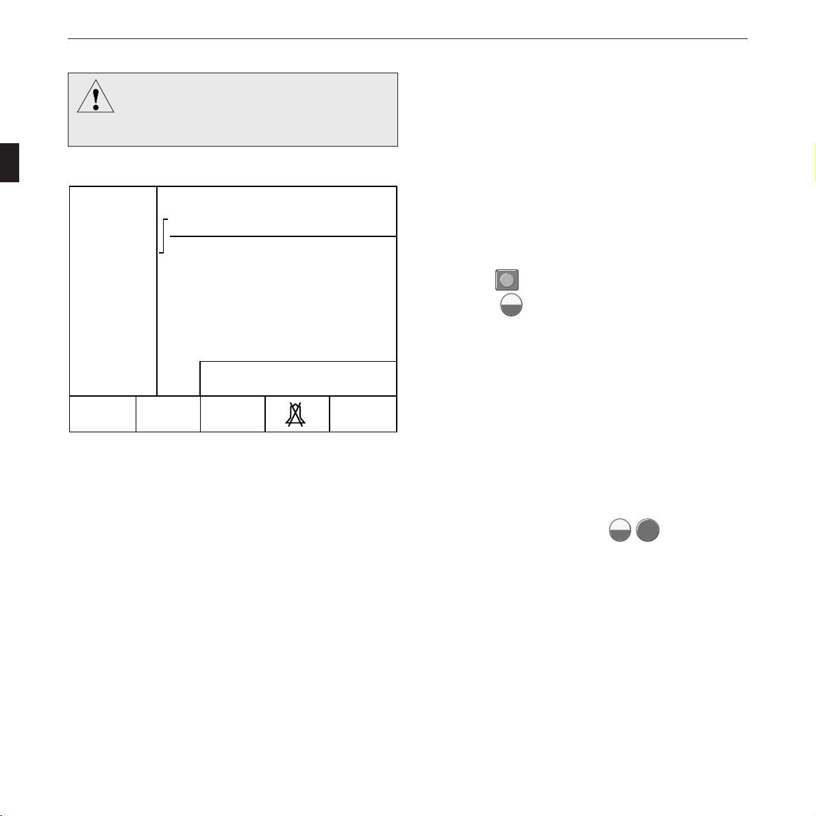
* Set the energy selector to 360 joules (50 joules, if inter-
nal electrodes are connected). The display first shows the
selected energy (Figure 3-8).
* Press the
2
3
Charge
Shock
button on the paddle to charge the unit.
(Press the
Charge
Shock
key on the defibrillator, when using
internal electrodes.)
You may now watch the defibrillator charging.
* When the selected energy level has been reached,
CardioServ beeps and the stored energy is displayed
(Figure 3-9).
* Trigger the defibrillation pulse within the next 30 sec-
onds. To do so, simultaneously press the buttons on
both paddles (or press the two
Charge
Shock
Shock
keys on the
defibrillator, when using internal electrodes).
If more than 5% of the available energy are lost before the
defibrillation pulse is triggered, CardioServ recharges until the
required energy level is reached.
Caution
Do not trigger more than 5 consecutive test
discharges (or internal safety discharges) within
15 minutes at max. energy setting.
0
Paddle
Next
MenuFreezeSpO2ECG
160 BPM
140 ECG
HR Alarm
360 J
Figure 3-8. Display of selected energy

Setting Up CardioServ and Testing Its Performance
227 446 32-D CardioServ V4.1 25
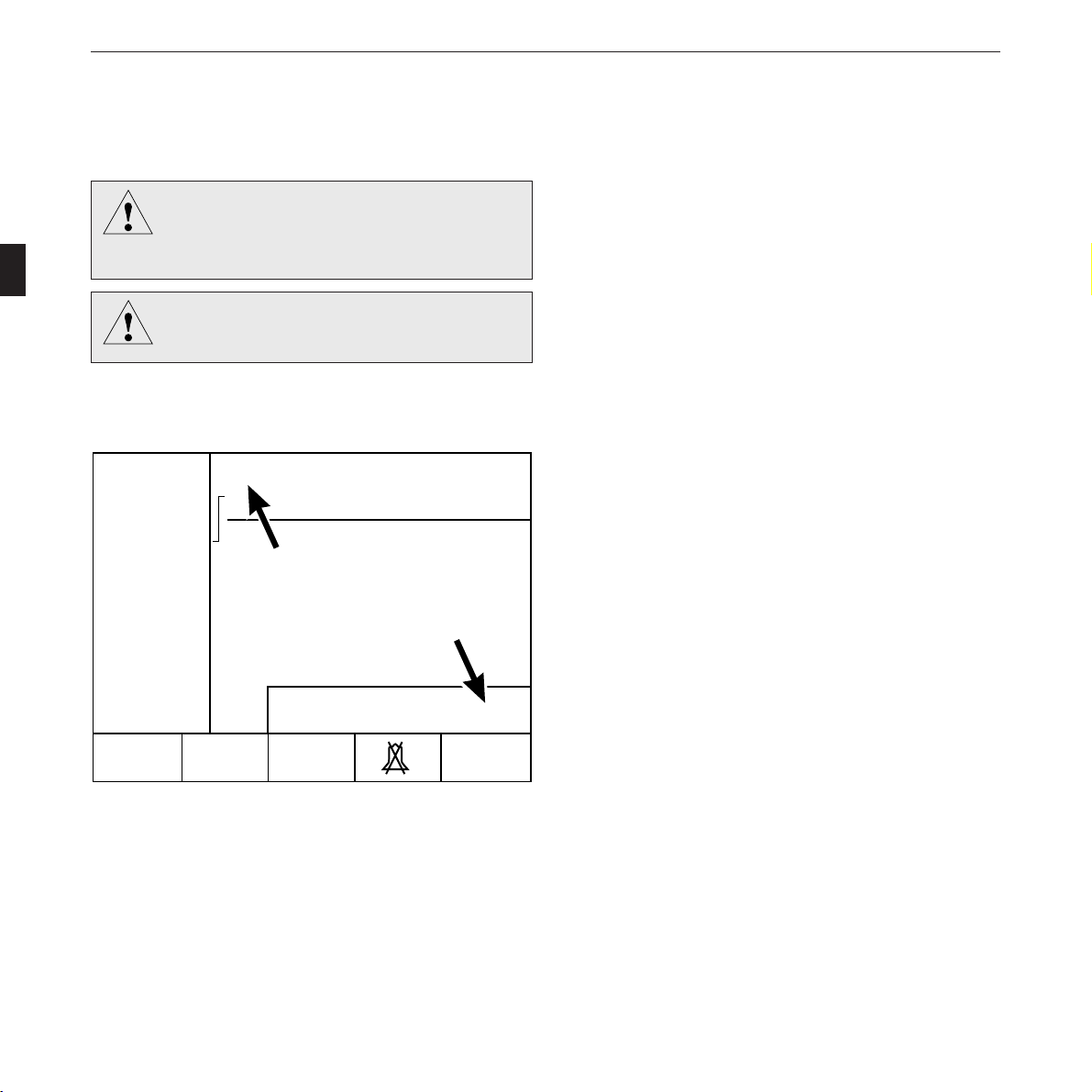
After defibrillation, the beeping sound stops, and the energy
actually delivered into a 50-ohm resistance is displayed for
10 seconds in place of the stored energy (Figure 3-9). The
delivered energy must not deviate more than ±15% or
±4 joules (whichever is greater) from the selected value. A
recording is initiated at the same time (16-second strip).
Should the discharge circuit be interrupted (paddles not
properly placed on contacts in the compartments, defective
lead), an internal safety discharge is initiated 200 ms after the
defibrillation shock has been triggered. In this case the “deliv-
ered energy” is “0”.
If the defibrillator cannot store the selected energy so that
selected and stored energy values differ, the LCD shows the
message “Energy high” or “Energy low”. The defibrillation
pulse can be triggeed all the same.
* Switch off CardioServ (set energy selector to ).
Testing the Pacemaker Performance
The performance of the pacemaker can be tested with a
commercially available pacemaker tester (e.g. CS300 Simula-
tor from Marquette Hellige, part no. 417 983-001).
0
Paddle
Energy
available
360 J
Next
MenuFreezeSpO2ECG
160 BPM
140 ECG
HR Alarm
Figure 3-9. Display of available energy
☞
If you do not trigger the defibrillation pulse within
30 seconds, an internal safety discharge is initiated
automatically.
Caution
The message “Energy high” or “Energy low”
indicates that CardioServ needs to be repaired.
If, in spite of this energy storage problem, the
device has to be employed, it will display the
message “Self-test failed. Charge Energy Error”
upon power up. In this situation press one of the
function keys and proceed as usual.
Caution
Performance Test
Test the defibrillator performance once a week:
test 1 – defibrillator connected to mains, battery
removed,
test 2 – defibrillator disconnected from mains,
battery inserted

Setting Up CardioServ and Testing Its Performance
26 CardioServ V4.1 227 446 32-D
For your notes

227 446 32-D CardioServ V4.1 27
Non-Synchronized Defibrillation
4. Non-Synchronized Defibrillation
This section describes first how to perform a non-synchro-
nized defibrillation, using the standard defibrillation
paddles. The subsequent explanations refer to the use of
internal and disposable adhesive electrodes.
At the end of this section you will find a summary of all
necessary operating steps (brief operating instructions).
28 CardioServ V4.1 227 446 32-D
Non-Synchronized Defibrillation
4.1 Defibrillation with Standard
Electrodes
The energy selector can be set to the autosequence position,
where the defibrillator automatically sequences the preset
energy levels. The preset factory default setting is the sequence
recommended by AHA/ERC (200 J, 200 J, 360 J). The
factory default values can be changed from the defaults menu.
You can choose among 150 J, 200 J, 300 J and 360 J.
* Set the energy selector (4) to “Autosequence” or to the
required energy value (this turns on CardioServ).
The defibrillator beeps and displays a checkered pattern (LCD
performance test). Next the main display appears (Figure
4-1). When a patient cable is connected the selected ECG
lead is displayed (selectable).
* Check that the energy selector locks in on the correct
position and that the display shows the selected energy
(Figure 4-1).
The energy depends on the defibrillation mode, on the
patient’s age and constitution. In external application the
thickness of the tissue is also a factor which influences the
amount of energy required.
The energy necessary for successful ventricular defibrillation
without damaging the myocardium has for many years been a
matter of scientific controversy. The manufacturer is therefore
not able to give any recommendations.
Warnin
g
The information given in section 1.2 must be
observed without fail to ensure safe and reliable
application of the device.
Dan
g
er
Always switch off CardioServ before exchanging
the defibrillation paddles.
Figure 4-1. Main display, indication of ECG lead, manual
operation and selected energy
0
Paddle
Next
MenuFreeze
SpO2ECG
200 J
160 BPM
140 ECG
HR Alarm
227 446 32-D CardioServ V4.1 29
Non-Synchronized Defibrillation
Figure 4-2. Removing the paddles
Warnin
g
Do not apply the paddles over
– sternum or clavicle
– nipples
– implanted pacemaker or defibrillator.
In emergency situations AHA recommends for adult patients
1. defibrillation with 200 joules; if unsuccessful, repeat
2. defibrillation with 200 joules; if unsuccessful, repeat
3. defibrillation with max. energy setting (360 joules).
Please note that children require less energy for successful
ventricular defibrillation than adults. For the first defibrilla-
tion pulse delivered to babies and small children, select an
energy level of 2 joules/kg body weight. For subsequent
shocks, the energy may be increased to 4 joules/kg.
In compliance with IEC requirements the energy adjusted on
this defibrillator is not the stored energy, but the energy
released into an external resistance of 50 ohms (patient resist-
ance + electrode-to-skin contact resistance). The energy
selector is labelled accordingly.
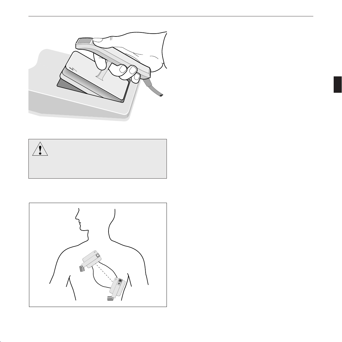
* Remove the paddles from their compartments (as shown
in Figure 4-2). Carefully dry the electrodes, if they are
wet. The handles, in particular, must be completely dry.
Apply an ample amount of electrode cream to each
paddle.
* Apply the electrodes to the patient’s thorax so that the
greatest possible amount of energy flows through the
myocardium (the imaginary connecting line between the
two electrode centers should be identical with the cardiac
median line; Figure 4-3).
* Press paddles firmly down onto the patient’s thorax..
Figure 4-3. Paddle application points
3
2
3
C
h
a
r
g
e
STERNUM
APEX
30 CardioServ V4.1 227 446 32-D
Non-Synchronized Defibrillation
0
Paddle
200 J
Next
Menu
FreezeSpO2ECG
160 BPM
140 ECG
HR Alarm
Energy
available
The ECG signal trace appears on the monitor.
* Do not touch the patient any more and warn all those
present.
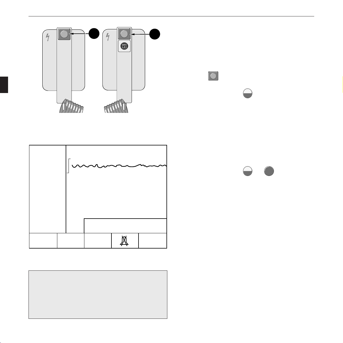
* Press the
2
3
Charge
Shock
button (8) on the apex paddle to initiate
charging (Figure 4-4). When using internal electrodes or
defibrillation pads, press
Charge
Shock
on the device.
When the selected energy level has been reached (message
“Energy available”), CardioServ beeps and the stored energy is
displayed (Figure 4-5).
* Trigger the defibrillation shock within the next 30 sec-
onds by simultaneously pressing the buttons on both
paddles (Figure 4-4). When using internal electrodes or
defibrillation pads, press
Charge
Shock
and
Shock
on the device.
If more than 5% of the available energy are lost before the
defibrillation shock is triggered, CardioServ recharges until
the required energy level is reached.
Figure 4-5. Display of available energy
2
3
Charge
Charge
Shock
8
2
3
Shock
STERNUM
APEX
Figure 4-4. Buttons to initiate energy storage and to trigger the
defibrillation shock
☞
When the defibrillator is already charged you can
increase the energy level simply by turning the energy
selector to the new setting. To decrease the energy
level, set the selector to the lower value and initiate
charging again.
 Loading...