

Page 1

Servicing Instructions
CardioServ/
CardioServVF
Version 4
227 483 02-B SA(e)
Page 2

Caution:
During repairs/service interventions,
observe the protective measures against
damage due to ESD.
* Marquette Hellige GmbH considers itself
responsible for the effects on safety ,
reliability, and performance of the equipment, only if:
- assembly operations, extensions,
readjustments, modifications, or
repairs are carried out by
Marquette Hellige GmbH or by
persons authorized by Marquette
Hellige GmbH,
- the electrical installation of the relevant room complies with the applicable national and local requirements,
and
- the instrument is used in accordance
with the instructions for use.
* This manual contains service information;
operating instructions are provided in the
operator’s manual of the instrument.
* This manual is in conformity with the
instrument at printing date.
* All rights are reserved for instruments,
circuits, techniques, and names appearing
in the manual.
©
Marquette Hellige GmbH
Printed in Germany
Page 3

Marquette Hellige GmbH CardioServ V.4 Page 3
Servicing Instructions
Contents
1. General Introduction...........................................................................................5
2. General overview of CardioServ........................................................................7
2.1 Documentation and nomenclature of Marquette Hellige instrument
part Nos ........................................................................................................ 7
2.1.1 Configuration of instrument part No ....................................................7
2.1.2 Configuration of the PCB part Nos......................................................7
2.1.3 Instrument status documentation (nominal status) .............................8
Instrument Versions ............................................................................9
3. Functional Description .....................................................................................11
3.1 Pcb. usage on different CardioServ ( 4.x ) Versions ...................................17
3.2 Important Servicing Note: .............................................................................21
4. Signal names.....................................................................................................23
4.1 Pin configuration of panel connectors...........................................................29
4.1.1 Socket SpO2 303 443 57 ..................................................................29
4.1.2 Socket ECG 303 442 99....................................................................30
4.1.3 Socket Option 303 445 17 .................................................................30
4.1.4 Socket Paddle 303 444 16 ................................................................31
5. Block Diagram CardioServ VF/V4...................................................................33
6. Assembly Instructions......................................................................................35
7. Troubleshooting Hints ......................................................................................37
7.1 Error Codes in the CardioServ Self-Test Screen ..........................................39
8. Adjustment Instructions ................................................................................... 41
9. Technical Specifications CardioServ/CardioServ VF .................................... 49
10. Maintenance and Technical Inspection...........................................................57
10.1 General Information ....................................................................................57
10.2 Testing Equipment ......................................................................................58
10.3 Visual Check ...............................................................................................60
10.4 Performance Check ....................................................................................60
10.4.1 Power-up Test .................................................................................60
10.4.2 Key Test...........................................................................................60
10.4.3 Printer Test .....................................................................................61
10.4.4 Energy Test ..................................................................................... 61
227 483 02-B SA(e)-98.05
Page 4

Marquette Hellige GmbH CardioServ V.4 Page 4
Servicing Instructions
10.4.5 Pacemaker Test (Without pacemaker testing adapter) ................... 62
10.4.6 Pacemaker Test (with Marquette Hellige testing adapter) ..............63
10.4.7 SPO2 Performance Check ..............................................................64
10.4.8 ECG Test .........................................................................................65
10.4.9 Cardioversion Test ...........................................................................65
10 4.10 Option Socket Input Test ..............................................................65
10.5 Battery ........................................................................................................ 66
11. Safety Analysis Test ..........................................................................................67
11.1. General introduction ...................................................................................67
11.2 Recommended Test Equipment ..................................................................67
11.3 Protective Earth Resistance Test ................................................................ 67
11.3.1 Leakage Current Measurement ......................................................68
11.3.2 Enclosure Leakage Current Test ....................................................68
11.3.3 Patient Leakage Current Test .........................................................69
12. Spare Parts Lists ............................................................................................... 71
13. Accessories: Car holder...................................................................................75
14. Appendix: Drawings
Revision History
December 1997 Initial Release SW Version 4
227 483 02-B SA(e)-98.05
Page 5

Marquette Hellige GmbH CardioServ V.4 Page 5
Servicing Instructions
1. General Introduction
CardioServ Semi-Automatic and Manual
There are 2 CardioServ models: the semi-automatic and the manual defibrillator. Both models are available with a pacemaker and SpO2.
The manual CardioServ is a defibrillator designed to deliver synchronized and unsynchronized shocks. This requires the user to trigger capacitor charging and shock delivery manually.
The semi-automatic defibrillator is equipped with analysis software, which monitors the ECG
for arrhythmias (fibrillation and ventricular tachycardia). When the analysis is started by
pressing a key the ECG is analyzed. If the result of the analysis is positive, the capacitor is
charged to the preselected energy level. The semiautomatic operating mode can be terminated by pressing a key or inserting the dongle.
227 483 02-B SA(e)-98.05
Page 6

Marquette Hellige GmbH CardioServ V.4 Page 6
Servicing Instructions
227 483 02-B SA(e)-98.05
Page 7
Marquette Hellige GmbH CardioServ V.4 Page 7
Servicing Instructions
2. General overview of CardioServ
2.1 Documentation and nomenclature of Marquette Hellige
instrument part Nos
2.1.1 Configuration of instrument part No
The instrument part No comprises 8 digits, the first 6 digits determining the instrument
type, the last 2 digits the instrument version. The language is determined by configuration,
thus having no influence on the part No.
E.g. Instrument Type Version
CardioServ 101 116 ..
without pacemaker 101 116 03
with SPO
with pacemaker and SPO
2
2
101 116 04
101 116 05
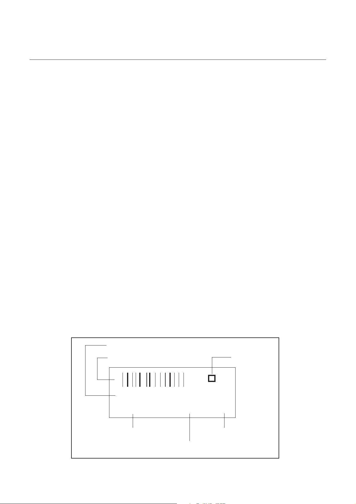
2.1.2 Configuration of the PCB part Nos
388 xxx yy Spare part numbers for the operative PCBs.
The instrument documentation, e.g., reference diagrams, circuit diagrams and parts lists
are listed under this part No.
The 388 number is located on the barcode label.
Configuration of the barcode labels:
Consecutive number
Consecutive number barcode Test mark
0000000219
388 011 51 3131 C3
227 483 02-B SA(e)-98.05
Part No. Parts list index
Test number (batch)
Page 8

Marquette Hellige GmbH CardioServ V.4 Page 8
Servicing Instructions
303 xxx yy Spare part numbers for PCBs tested especially thoroughly
303 numbers are only given to PCBs where the level of testing applied to 388 PCBs is
inadequate for implementation when servicing in the field, or where only a complete set of
PCBs can be replaced in the field.
In addition to a barcode label (388 number) 303 part Nos also have an additional label with
a 303 number and are to be found in the spare parts list under this number.
389 xxx yy Replacement numbers for defective PCBs
Where servicing is required 389 PCBs are available for the replacement of some PCBs.
When using a replacement PCB (389 part No) the defective PCB is to be returned to the
Freiburg factory. Replacement PCB part Nos are included in the spare parts list.
389 PCBs have an additional adhesive label.
2.1.3 Instrument status documentation (nominal status)
Due to the hardware and software combination unambiguous documentation of the instrument assembly status is necessary, also in the event of repairs.
This documentation comprises the following documents and measures:
Master Record Index (MRI) (see Appendix)
This document is a component of this instrument documentation.
This document states the combination of permissible hardware and software for a particular instrument version. The permissible PCB Index is given in the Index column with each
update delivered. Further permissible PCB Indexes are given in the compatible column.
The PCB Index can be found in the PCB barcode label.
Product Status Index
This document is created during manufacture. The Product Status Index documents the
hardware/software product status.
227 483 02-B SA(e)-98.05
Page 9

Marquette Hellige GmbH CardioServ V.4 Page 9
Servicing Instructions
Instrument Versions
These servicing instructions describe the manual CardioServ and the semiautomatic CardioServ VF
Manual CardioServ
101 117 01 CardioServ without pacemaker, without SPO2
101 117 03 CardioServ with pacemaker, without SPO2
101 117 04 CardioServ without pacemaker, with SPO2
101 117 05 CardioServ with pacemaker, with SPO2
101 117 02 CardioServ Esaote without pacemaker, without SPO2
101 117 06 CardioServ Esaote with pacemaker, without SPO2
101 117 07 CardioServ Esaote without pacemaker, with SPO2
101 117 08 CardioServ Esaote with pacemaker, with SPO2
101 117 09 CardioServ USA without pacemaker, without SPO2
101 117 11 CardioServ USA with pacemaker, without SPO2
101 117 12 CardioServ USA without pacemaker, with SPO2
101 117 13 CardioServ USA with pacemaker, with SPO2
CardioServ VF
101 117 21 CardioServ without pacemaker, without SPO2
101 117 22 CardioServ with pacemaker, without SPO2
101 117 23 CardioServ without pacemaker, with SPO2
101 117 24 CardioServ with pacemaker, with SPO2
101 117 29 CardioServ Esaote without pacemaker, without SPO2
101 117 30 CardioServ Esaote with pacemaker, without SPO2
101 117 31 CardioServ Esaote without pacemaker, with SPO2
101 117 32 CardioServ Esaote with pacemaker, with SPO2
101 117 25 CardioServ USA without pacemaker, without SPO2
101 117 26 CardioServ USA with pacemaker, without SPO2
101 117 27 CardioServ USA without pacemaker, with SPO2
101 117 28 CardioServ USA with pacemaker, with SPO2
227 483 02-B SA(e)-98.05
Page 10

Marquette Hellige GmbH CardioServ V.4 Page 10
Servicing Instructions
227 483 02-B SA(e)-98.05
Page 11

Marquette Hellige GmbH CardioServ V.4 Page 11
Servicing Instructions
3. Functional Description
The Therapy System CardioServ comprises a defibrillator, a monitor ( LC display 240 * 320
pixels ), a printer and a power supply unit. These components are arranged in a casing. It is a
compact unit, which can also be implemented using a 230-V power supply system, even
without a battery. The unit has a pulsed 140-mA standard charge for the battery. Additional
versions available have an external pacemaker and an SpO2 module, separately or combined.
The Defi is switched on by turning the rotary switch to position ECG or energy levels automatic sequence 2 ... 360 J.
Following a self-test, which tests
- RAM data store
- ROM program memory
- Watchdog / Reset
- EEPROM permanent memory
- Display all Pixels on / off
- Time base of internal quartz crystal
- Energy charge from last shock
- Defective charge or Defib keys
- Position of energy selector switch
- Connected electrodes
- Pacemaker
- SpO2
the Defi is ready for operation. If an error arises, depending on the severity of the error, the
Defi is either on standby or not. Serious errors are watchdog, ROM or RAM errors. In the
case of minor errors, an error message appears, but the instrument can be rendered operative by pressing a key.
The Defi shock is delivered via exchangeable paddles. This permits the use of different electrodes, i.e., in addition to conventional electrodes, large-surface adhesive electrodes or internal electrodes, for example. Adhesive electrodes are used for the pacemaker. The CardioServ also has Start and Trigger buttons on the instrument.
The charge operation is actuated with the Charge key on the apex electrode (for internal and
adhesive electrodes on the instrument). During the charge operation, the accumulation of
energy is registered and when the selected energy level has been reached the energy to be
released appears on the display. An acoustic and visual display on the monitor indicates the
configured energy level has been reached. When the battery is fully charged or with linepower operation, charging at 360 J should take about 8 s.
227 483 02-B SA(e)-98.05
Page 12

Marquette Hellige GmbH CardioServ V.4 Page 12
Servicing Instructions
The buttons on both electrodes are pressed to trigger the defibrillation pulse (safety two-hand
operation). This means that the button on the apex electrode (or the corresponding one on
the instrument) has two functions:
- start the charge operation
- trigger defibrillation (together with the Trigger button)
The type of electrodes connected are recognized and, in the case of internal electrodes, the
energy is automatically limited to 50 joules.
Following defibrillation, the energy released is displayed on the screen for 6 seconds. Documentation output is by the printer.
The defibrillator has three operating modes:
* synchronized defibrillation (cardioversion)
* unsynchronized defibrillation (emergency therapy)
* semi-automatic (emergency service)
Cardioversion (operating mode Sync) can proceed either via the paddles or a patient cable.
The operating mode Sync appears on the display and Sync marks are superimposed on the
display. Following cardioversion, for safety reasons, the CardioServ switches automatically
over to the unsynchronized operating mode, i.e., before each cardioversion the instrument
must be switched over to Sync.
The Defi can be configured for semi-automatic operation in three ways:
* As a semi-automatic instrument only (defibrillation only possible via analysis)
* Semi-automatic instrument which can be toggled to manual mode by pressing a key
* Semi-automatic instrument which can be reset into manual mode using a dongle
ECG signal pick-up is possible via the paddles or ECG cable. ECG is output on the LCD
display or by the built-in 50-mm printer.
A safety device ensures the discharge of the storage capacitor in the following situations:
- when defibrillation is not triggered 30 seconds after storage operation is complete,
- 0.2 seconds after triggering defibrillation,
- immediately after switching back the energy selector switch during or after storage,
- when the battery voltage drops below a certain level,
- when the selected energy level still has not been reached after 32 seconds.
When switching to a higher energy level, the energy deficit is supplied by recharging.
227 483 02-B SA(e)-98.05
Page 13

Marquette Hellige GmbH CardioServ V.4 Page 13
Servicing Instructions
Pacemaker
The pacemaker is a transthoracic pacemaker operating in the Demand and Fix mode.
- Pulse width 40ms (20 ms)
- The frequency is between 0...180 P/min (> 150 P/min only 20ms pulse width)
- The current is between 0...200 mA
- Adjustment is in 5-unit intervals.
The pacemaker is operated using 6 keys on the control panel. One key switches the pacemaker on, one key changes the operating mode, the other keys are used to adjust the frequency and current. The defibrillator cannot be disabled as long as the pacemaker is
switched on. The adhesive electrodes of the Defi are used to release a pulse. This ensures a
rapid switch from defibrillator to pacemaker and back again.
SpO
2
SpO2 is based on one of the modules manufactured by Nellcor (MP204). This module is
located on the PCB Analog and receives its power supply from the latter. Measurement of the
oxygen saturation level and pulse frequency is made by this PCB.
Pulse frequency from 0...250 P/min
Saturation from 0...100%
We display the plethysmogram, saturation level and, when selected, the pulse frequency
instead of the HR.
Control options:
A battery charge check is performed under load application. The message charge battery
on the display means the battery needs recharging. At least five discharges at maximum
energy are still possible. (Possibly even considerably more)
Performance check of defibrillation is performed by discharging into the integrated 50-ohm
resistor.
Monitoring battery charge via the connector for power cord by the yellow LED. If the battery is
fully charged after 16 h, trickle charging ensues, the yellow LED is permanently lit up.
The monitoring function of the CardioServ records and monitors the ECG and oxygen saturation level. The cardiac-action potentials are fed to the ECG preamplifier via a 5-wire patient
cable. Selection can be made from 12 leads. The ECG curve is displayed on the LC screen
with an illuminated background. The heart rate obtained from the ECG signal is continuously
displayed on the screen.
Communication between the user and the instrument is via the keyboard and the LC screen.
These also serve to configure the default settings and functions (see Users Manual for further details).
227 483 02-B SA(e)-98.05
Page 14

Marquette Hellige GmbH CardioServ V.4 Page 14
Servicing Instructions
The PCBs have the following functions:
PCB Power Supply
This PCB supplies the 16.5-V instrument power supply. 10 A can be supplied for short-term
capacitor charging. It is a primary clock-rated wide-range power supply system. It operates
from 85 .. 264 V, at 49 ... 65 Hz. It is protected by 2 fuses in the primary circuit. One on the
PCB and one in the feed line.
PCB Analog
This PCB has several functional units.
The first unit accepts the ECG signals (patient input) received via the patient cable from the
patient. In accordance with its task, it is connected to the patient by a cable. It is thus
constructed as an application component isolated from other circuit components and the
circuit reference (floating). The tasks of this circuit component are:
- amplification of ECG signals
- lead selection (lead selector)
- identification and reporting of electrode defects
- identification and reporting of patient lead connection
- digitization and serialization of ECG data
- potential separation of the application component from the remaining circuit components
(floating)
- floating component power supply
- ECG trigger
- pacing-pulse detection
There are two of these circuit components on this PCB. Once for the ECG via paddles, once
for the ECG via patient cable.
A second unit provides floating separation and the power supply for SPO2.
A further circuit component controls high-voltage generation for the Defi shock. There is a
high-voltage capacitor on this PCB. The functions are as follows :
- safety control during charging and shock release (1st path : hardware)
- controlling storage operation and energy release, independent of the CPU
- controlling the high-voltage generator
- elimination of interference in the operating elements in the Defi electrodes
- conversion of the voltage and current signals into a frequency to measure energy
- activation and control of the high-voltage transformer
- generation of the emergency cutoff signal in the event of inadmissibly high voltage
- measurement of the high voltage on the primary winding of the high-voltage transformer
227 483 02-B SA(e)-98.05
Page 15

Marquette Hellige GmbH CardioServ V.4 Page 15
Servicing Instructions
- rectification of the high voltage
- protection of the high-voltage diode
- discharging the storage capacitor as a safety precaution
- measurement of the high voltage on the storage capacitor
- energy delivery via the high-voltage relay
A further unit organizes the entire instrument´s power supply. This is provided by the built-in
battery, the power supply unit or, optionally, from an external battery (e.g., ambulance power
supply system). It has the following tasks:
- switching instrument on/off
- automatic cutoff when battery voltage is too low
- monitoring the “charge battery” threshold
- power source selection: battery or power supply system
- charging the built-in battery by a special circuit independent of how high the supply
voltage is
PCB Digital
The PCB Digital is equipped with the microcontroller, which controls the entire instrument. It
comprises a Motorola 68332 microcontroller, RAM, EPROM, EEPROM, watchdog and I/O
ports. It has the following functions:
- safety control during charging and shock release (2nd path : software)
- displaying the ECG and text on the LC screen (delete bar procedure)
- processing the curves and texts for the printer controller for output onto paper
- 50 / 60-Hz filter (software)
- alarm management
Circuit component display :
- graphics controller to control the display, which ensures screen refresh
- display RAM
- generation of voltages for the LCD ( LCD power supply )
- generation of high voltage for background illumination
- Pal for chip select generation for display
- contrast adjustment
Circuit component real-time clock :
- real-time clock with lithium battery buffer and integrated quartz crystal
- Pal for chip select generation for clock
Circuit component 1-channel recorder :
- single-chip microcontroller to output data at thermal-array printhead
- monitoring printhead temperature
- motor control for paper transport
- switches off motor in the event of overload or underload
227 483 02-B SA(e)-98.05
Page 16

Marquette Hellige GmbH CardioServ V.4 Page 16
Servicing Instructions
- generation of power supply voltages for the recorder
- processing of all signals for the printer microcontroller
Further circuit components on the PCB are :
- generation of 5 V from 12 V via an integrated switching controller, short-circuit-proof and
protected against overvoltage by Transzorb diodes
- sound generator, frequency controlled by SW
- RS-232 interface, protected against overvoltage by Transzorb diodes. Interface integrated
into microcontroller, external conversion of level from 5 V to +- 12 V.
- energy selector switch, binary coded, delivers its information to PCB Analog and to the
microcontroller
- keyboard interface to connect the membrane keypad
- control of LEDs on the keypad
- watchdog
- reset generation, when +5-V supply drops below 4,65 V or exceeds 5,5 V
- RAM buffering by battery when instrument is switched off
- pacemaker functions integrated on PCB Digital
- serial hookup of pacemaker and microcontroller
- pacemaker conducts current when in operative mode only.
227 483 02-B SA(e)-98.05
Page 17

Marquette Hellige GmbH CardioServ V.4 Page 17
Servicing Instructions
3.1 Pcb. usage on different CardioServ ( 4.x ) Versions
Pcb.Digital Pcb.Digital Pcb.Analog Pcb.Power Pcb.SPO2
Spare Spare Spare. Supply Spare
388 032 06 388 032 53 303 445 43 Spare 930 117 26
Exchange Exchange Exchange 930 118 46
389 004 25 389 004 26 389 004 22
CardioServ 101 117 01
Version 4.x x x x
without pacemaker /
without SPO2
CardioServ 101 117 03
Version 4.x x x x
with pacemaker /
without SPO2
CardioServ 101 117 04
Version 4.x x x x x
without pacemaker /
with SPO2
CardioServ 101 117 05
Version 4.x x x x x
with pacemaker /
with SPO2
CardioServ 101 117 09
Version 4.x USA x x x
without pacemaker /
without SPO2
CardioServ 101 117 11
Version 4.x USA x x x
with pacemaker /
without SPO2
CardioServ 101 117 12
Version 4.x USA x x x
without pacemaker /
with SPO2
CardioServ 101 117 13
Version 4.x USA x x x x
with pacemaker /
with SPO2
227 483 02-B SA(e)-98.05
Page 18

Marquette Hellige GmbH CardioServ V.4 Page 18
Servicing Instructions
Pcb.Digital Pcb.Digital Pcb.Analog Pcb.Power Pcb.SPO2
Spare Spare Spare. Supply Spare
388 032 06 388 032 53 303 445 43 Spare 930 117 26
Exchange Exchange Exchange 930 118 46
389 004 25 389 004 26 389 004 22
CardioServ 101 117 02
Version 4.x x x x
ESAOTE
without pacemaker /
without SPO2
CardioServ 101 117 06
Version 4.x x x x
ESAOTE
with pacemaker /
without SPO2
CardioServ 101 117 07
Version 4.x x x x x
ESAOTE
without pacemaker /
with SPO2
CardioServ 101 117 08
Version 4.x x x x x
ESAOTE
with pacemaker / with SPO2
227 483 02-B SA(e)-98.05
Page 19

Marquette Hellige GmbH CardioServ V.4 Page 19
Servicing Instructions
Pcb. usage on different CardioServ VF ( 4.x ) Versions
Pcb.Digital Pcb.Digital Pcb.Analog Pcb.Power Supply Pcb.SPO2
Spare Spare Spare. Spare Spare
388 032 06 388 032 53 303 445 43 930 118 46 930 117 26
Exchange Exchange Exchange
389 004 25 389 004 26 389 004 22
CardioServ 101 117 21
Version 4.x x x x
without pacemaker /
without SPO2
CardioServ 101 117 22
Version 4.x x x x
with pacemaker /
without SPO2
CardioServ 101 117 23
Version 4.x x x x x
without pacemaker /
with SPO2
CardioServ 101 117 24
Version 4.x x x x x
with pacemaker /
with SPO2
CardioServ 101 117 25
Version 4.x USA x x x
without pacemaker /
without SPO2
CardioServ 101 117 26
Version 4.x USA x x x
with pacemaker /
without SPO2
CardioServ 101 117 27
Version 4.x USA x x x
without pacemaker /
with SPO2
CardioServ 101 117 28
Version 4.x USA x x x
with pacemaker /
with SPO2
227 483 02-B SA(e)-98.05
Page 20

Marquette Hellige GmbH CardioServ V.4 Page 20
Servicing Instructions
Pcb.Digital Pcb.Digital Pcb.Analog Pcb.Power Supply Pcb.SPO2
Spare Spare Spare. Spare Spare
388 032 06 388 032 53 303 445 43 930 118 46 930 117 26
Exchange Exchange Exchange
389 004 25 389 004 26 389 004 22
CardioServ 101 117 29
Version 4.x
ESAOTE x x x
without pacemaker /
without SPO2
CardioServ 101 117 30
Version 4.x
ESAOTE x x x
with pacemaker /
without SPO2
CardioServ 101 117 31
Version 4.x
ESAOTE x x x x
without pacemaker /
with SPO2
CardioServ 101 117 32
Version 4.x
ESAOTE x x x x
with pacemaker /
with SPO2
227 483 02-B SA(e)-98.05
Page 21

Marquette Hellige GmbH CardioServ V.4 Page 21
Servicing Instructions
3.2 Important Servicing Note:
Replacing CardioServ PCBs
When CardioServ PCBs are replaced the technician must call up the self-test screen after
replacing the PCB. The new components are reported automatically in the software configuration. After restarting CardioServ recognizes the new components. This is important in the
case of SpO2 and Pacemaker. Further the Performance Check (see on Page 62) needs to
be accomplished.
Replacing PCB Digital
The identification numbers 0000 and 1111 are stored in the Eeprom of the PCB Digital for
CardioServ Manual and CardioServ VF, respectively.
The replacement PCB always has the identification number 0000 stored in the Eeprom for
CardioServ Manual.
If during servicing the replacement PCB Digital is inserted into a CardioServ VF, when it is
switched on the CardioServ is in the manual mode. The following combinations of keys are
required to switch the CardioServ from manual to semi-automatic operation.
1. Press F1 and F5 keys simultaneously: The function Configuration appears on the screen.
2. Press F3 and F4 keys simultaneously: The function Key Test appears on the screen.
3. Press the Analysis key.
4. Press F3 and F4 keys simultaneously.
The identification code for the CardioServ VF stored in the Eeprom of the PCB Digital is now
1111 and the CardioServ operates in the semi-automatic mode.
227 483 02-B SA(e)-98.05
Page 22

Marquette Hellige GmbH CardioServ V.4 Page 22
Servicing Instructions
227 483 02-B SA(e)-98.05
Page 23
Marquette Hellige GmbH CardioServ V.4 Page 23
Servicing Instructions
4. Signal names
Interface Signals PCB DIGITAL <-> PCB ANALOG Connector
Note: I/O from processor 68332 viewpoint
Signal Name I/O Meaning Level Polarity
ENSELD-ENSELA I/O Selection of energy level or device On/Off +5V ---
TACHARGE ---- Charging signal from keypad +5V high-active
TADISCHARGE ---- Discharge signal from keypad +5V high-active
TAENABLE O Release signal for shock release via keypad +5V high-active
CHARGE_ I Charging OR signal from keypad and paddle +5V low-active
DISCHARGE_ I Discharge OR signal from keypad and paddle +5V low-active
PAPRINT I Triggers printout +5V high-active
or position ECG
DCBA
HHHH -> locked mechanically, reaction to error
HHHL -> Device off
HHLH -> ECG
HHLL -> 2J
HLHH -> 5J
HLHL -> 7J
HLLH -> 10J
HLLL.-> 20J
LHHH -> 30J
LHHL -> 50J
LHLH -> 70J
LHLL -> 100J
LLHH -> 150J
LLHL.-> 200J
LLLH -> 300J
LLLL -> 360J
ENERGY- L=enables HV generator start
SELECTED O H=switches HV generator and HV off
RELEASE I Message D relay on +5V high-active
SYNC_ O Triggers Defi shock in SYNC mode off. +5V low-active
RESDEF_ O Reset Defi +5V low-active
AIMESS O Enables pick-up of C relay, toggles between +5V high-active
RELE O Switches E relay on, thereby enabling pick-up +5V high-active
Reset position or lead interrupt = high +5V low-active
Is low in normal mode. Prevents shock release
when high
current and voltage measurement
L=C relay off, voltage reading
H=C relay on, current reading
of C relay
L=E relay not picked up
H=E relay picked up
227 483 02-B SA(e)-98.05
Page 24
Marquette Hellige GmbH CardioServ V.4 Page 24
Servicing Instructions
Signal Name I/O Meaning Level Polarity
GEST I With a L->H change shows when the generator was +5V high-active
ELEC1 - ELEC3 I Defi Electrode Identification
U_F I Current or Voltage Measurement Converted into +5V ----
PWON_ ---- Stop Signal for Electronic Relay (Device-On/Off) low-active
BATLOW_ I Battery Undervoltage +5V low-active
BATLAD_ I Battery Charge Display +5V low-active
12VBAT ---- 12-V Standby Power Supply for Static RAMs +12V ----
LINE ---- Line-Power Operation Display +12V high-active
MISOEXT I Master-In Slave-Out (Buffered) +5V ----
MOSIEXT O Master-Out Slave-In (Buffered) +5V ----
SCKEXT O QSPI Serial Clock (Buffered) +5V ---PCS1EXT_ O Peripheral Chip Select1 (Buffered) +5V low-active
started and with H->L change when the selected
energy level is reached. (Detection by oscillator
reverse voltage)
321
HHH -> External Electrode
HLL -> Adhesive Electrode
LHL -> Internal Electrode
Other +5V ----
Frequency
PCS2EXT_ O Peripheral Chip Select2 (Buffered) +5V low-active
GND ---- Ground Reference Level 5-V Supply 0V ----
+5V ---- +%V Power Supply +5V
RESETB_ O Buffered Reset Signal +5V low-active
RX_SPO2 I UART Signal Received Data for SPO2 +5V -----
TX_SPO2 O UART Signal Transmit Data for SPO2 +5V -----
EKTRIG_ O ECG Trigger für SPO2 +5V -----
RESSPO2 O Reset SPO2 +5V low-active
RxD I Receive Data RS232 +5V
TxD O Transmit Data RS232 +5V
GND1V O Ground Analog 1Volt Out +5V
A!VOUT O Signal Analog 1Volt Out +5V
227 483 02-B SA(e)-98.05
Page 25
Marquette Hellige GmbH CardioServ V.4 Page 25
Servicing Instructions
Interface Signals PCB DIGITAL <-> PCB ANALOG Connector PS
Signal Name I/O Meaning Level Polarity
GND_ANA ---- Ground 0V ----
+12V_ANA ---- +12V Power Supply +12V ----
+5V-ANA ---- +5V Power Supply +5V ----
Interface Signals PCB DIGITAL <-> Printhead/Motor Interface Connector PRINT
Note: I/O from processor 80C51 or motor control viewpoint
Signal Name I/O Meaning Level Polarity
KLA, O Printhead Latch Signal +5V high-active
KCLK O Printhead Clock Signal +5V L->H
KDAT O Printhead Data Signal +5V ----
KSTRB O Printhead Strobe Signal +5V high-active
TERM1 I Printhead Thermistor Connector1 +5V ----
TERM2 I Printhead Thermistor Connector2 +5V ----
GNDJ ---- Ground Thermal-Array Printhead 0V ----
+5V ---- ++5V Power Supply Thermal-Array Printhead +5V ----
+22V ---- +22V Power Supply Thermal-Array Printhead +22V ----
VDD1 O Release Signal for Thermal-Array Printhead Overvoltage +22V high-active
MOTOR+ O Motor Connector + var ----
MOTOR- O Motor Connector - var ----
SENSE I Motor Current Sensor Signal var ----
227 483 02-B SA(e)-98.05
Page 26
Marquette Hellige GmbH CardioServ V.4 Page 26
Servicing Instructions
Interface Signals PCB DIGITAL <-> LCD Connector AD (HOSIDEN HLM6323)
Note: I/O from Graphics Controller viewpoint
Signal Name I/O Meaning Level Polarity
V0 O Contrast Voltage var. ----
VEE ---- Negative Power Supply for LCD -23V ----
D3-D0 O Serial Pixel Data +5V ----
M O LCD Drive Signal (AC Signal) +5V ----
VSS ---- Ground +0V ----
VDD ---- +5V Power Supply +5V ----
CP2 ---- Display Data Shift Clock +5V H->L
CP1 ---- Display Data Latch Signal +5V H->L
S O Frame Signal +5V high-active
DISP_OFF_ O Display ON/OFF
FG ---- Frame Ground 0V ----
H=Display ON
L=Display OFF +5V low-active
Interface Signals PCB DIGITAL <-> LCD Connector AE (HOSIDEN HLM8619)
Note: I/O from Inverter viewpoint
Signal Name I/O Meaning Level Polarity
FL HOT O High Voltage for CCFT ---- ----
FL GND O High-Voltage Ground ---- ----
227 483 02-B SA(e)-98.05
Page 27
Marquette Hellige GmbH CardioServ V.4 Page 27
Servicing Instructions
Interface Signals PCB DIGITAL<->LCD Connector AF (OPTREX DMF50174NF- FW)
Note: I/O from Graphics Controller viewpoint
Signal Name I/O Meaning Level Polarity
FLM O Frame Signal +5V high-active
LP ---- Data Latch Signal +5V H->L
CP O Clock Signal for Shifting Serial Ddta +5V H->L
M O Alternate Signal for LCD Drive +5V ----
VADJ ---- Contrast Signal var ----
VCC_ ---- +5V Power Supply +5V ----
VSS ---- Ground 0V ----
VEE ---- -23V Power Supply -23V ----
D3-D0 O Display Data +5V ---DISP_OFF__ O Display ON/OFF
H=Display ON
L=Display OFF +5V low-active
Interface Signals PCB DIGITAL<->LCD Connector AG (OPTREX DMF50174NF- FW)
Note: I/O from Inverter viewpoint
Signal Name I/O Meaning Level Polarity
FL HOT O High Voltage for CCFT ---- ----
FL GND O High-Voltage Ground ---- ----
227 483 02-B SA(e)-98.05
Page 28
Marquette Hellige GmbH CardioServ V.4 Page 28
Servicing Instructions
Interface Signals PCB DIGITAL <-> Keypad Interface Connector AH
Note: I/O from processor 68332 viewpoint
Signal Name I/O Meaning Level Polarity
KBROW0_
KBROW1_
KBROW2_
KBROW3_ O Keypad Matrix Columns +5V low-active
KBCOL0_
KBCOL1_
KBCOL2_
KBCOL3_ I Keypad Matrix Lines +5V low-active
TAENABLE O Release Signal for Key Charge/Defib + Defib +5V high-active
TACHARGE I Charge/Defib Key +5V high-active
TADISCHARGE I Defib Key +5V high-active
ON_OFF_ O On/Off Key +5V ----
GND ---- Ground 0V ----
LINE ---- Line LED +12V high-active
BAT O Battery Undervoltage LED +5V high-active
Interface Signals PCB Potential Separation <->Nellcor MP204
Signal Name I/O Meaning Level Polarity
TX O Transmit +5V high-active
RX O Receive +5V high-active
EK_SYN 1 ECG Trigger Signal +5V high-active
RESET_ 0 Reset +5V low-active
GNDF ---- Ground 0V ----
227 483 02-B SA(e)-98.05
Page 29

Marquette Hellige GmbH CardioServ V.4 Page 29
Servicing Instructions
4.1 Pin configuration of panel connectors
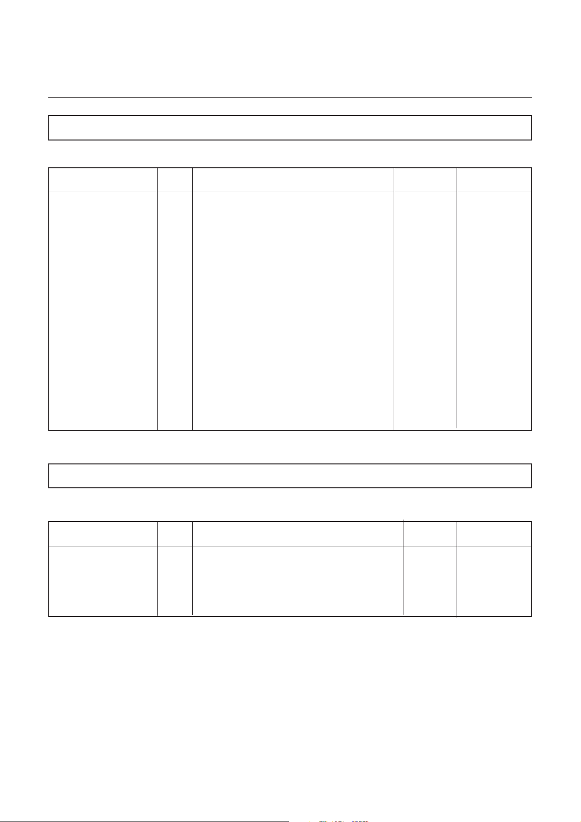
4.1.1 Socket SpO2 303 443 57
Marquette Hellige input socket, circular version
Blue mark on plug
On device
1 Anode Photodetector
2nc
3nc
4 Cathode Photodetector
5 GND
6 R(cal)
7 LED - (Red LED Cathode, IR_LED Anode)
8nc
9
6
10
8
Front view
7
5
2
4
1
3
6
9 LED + (Red LED Anode, IR_LED Cathode)
10 GND Screen
227 483 02-B SA(e)-98.05
Page 30
Marquette Hellige GmbH CardioServ V.4 Page 30
Servicing Instructions
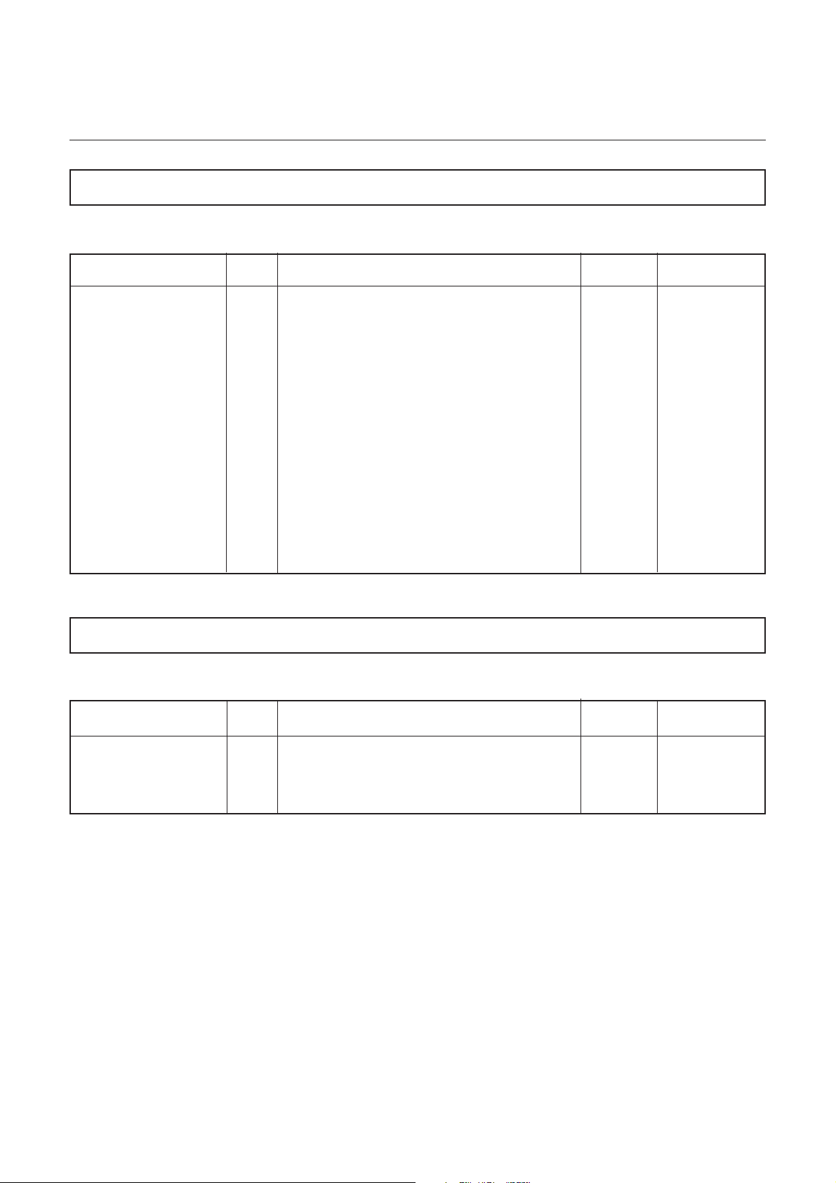
4.1.2 Socket ECG 303 442 99
Marquette Hellige input socket, circular version
Green mark on plug
5-Lead Cable 3-Lead Cable
1 Input R R
2 Input C L
3 Input F F
8
6
3
1
10
4
9
7
5
2
6
4 Input N --5 Input L --6 Ident Cable Connected Ident Cable Connected
7 GND floating GND floating
8 --- --9 Ident 5-Lead Cable --10 Screen Screen
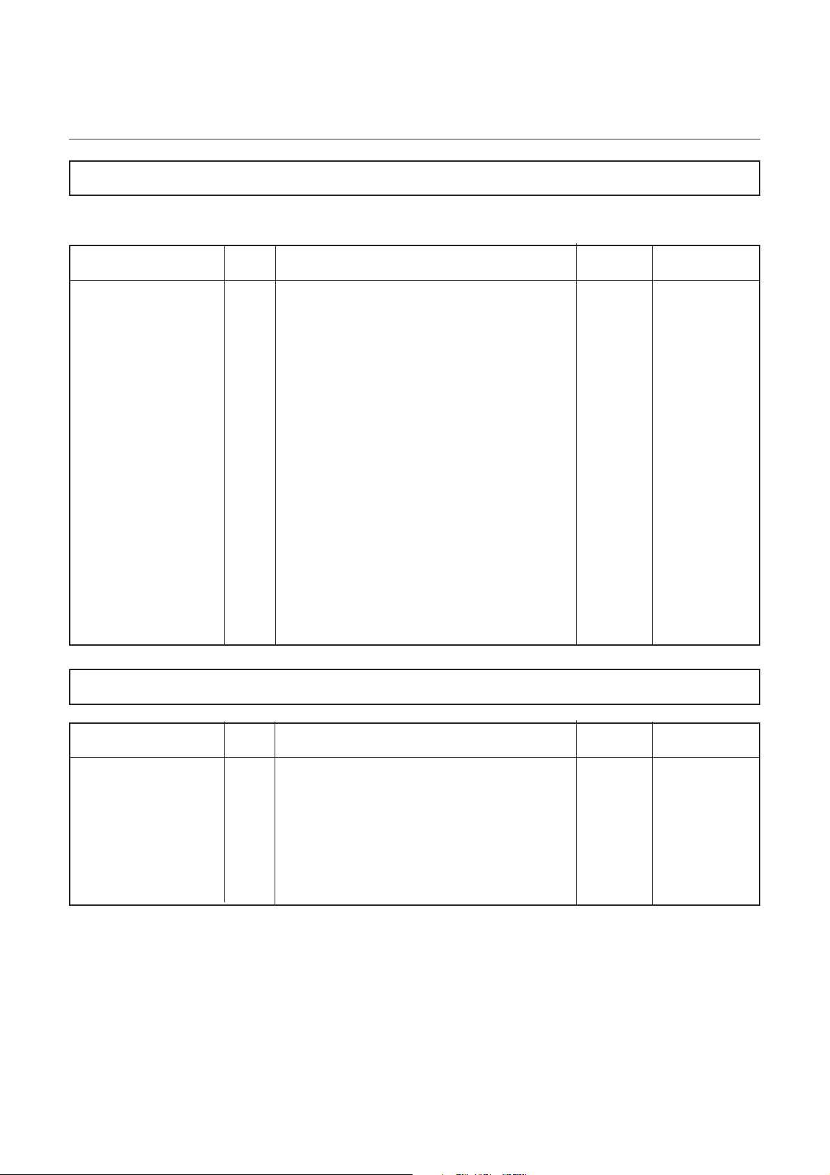
4.1.3 Socket Option 303 445 17
1 --2TX
3RX
Front view
2
5
7
9
6
1
4
10
3
6
8
4 --5 --6 --7 GNO
8 VCC
9 ECG
10 GND ECG
227 483 02-B SA(e)-98.05
Front view
Page 31

Marquette Hellige GmbH CardioServ V.4 Page 31
Servicing Instructions
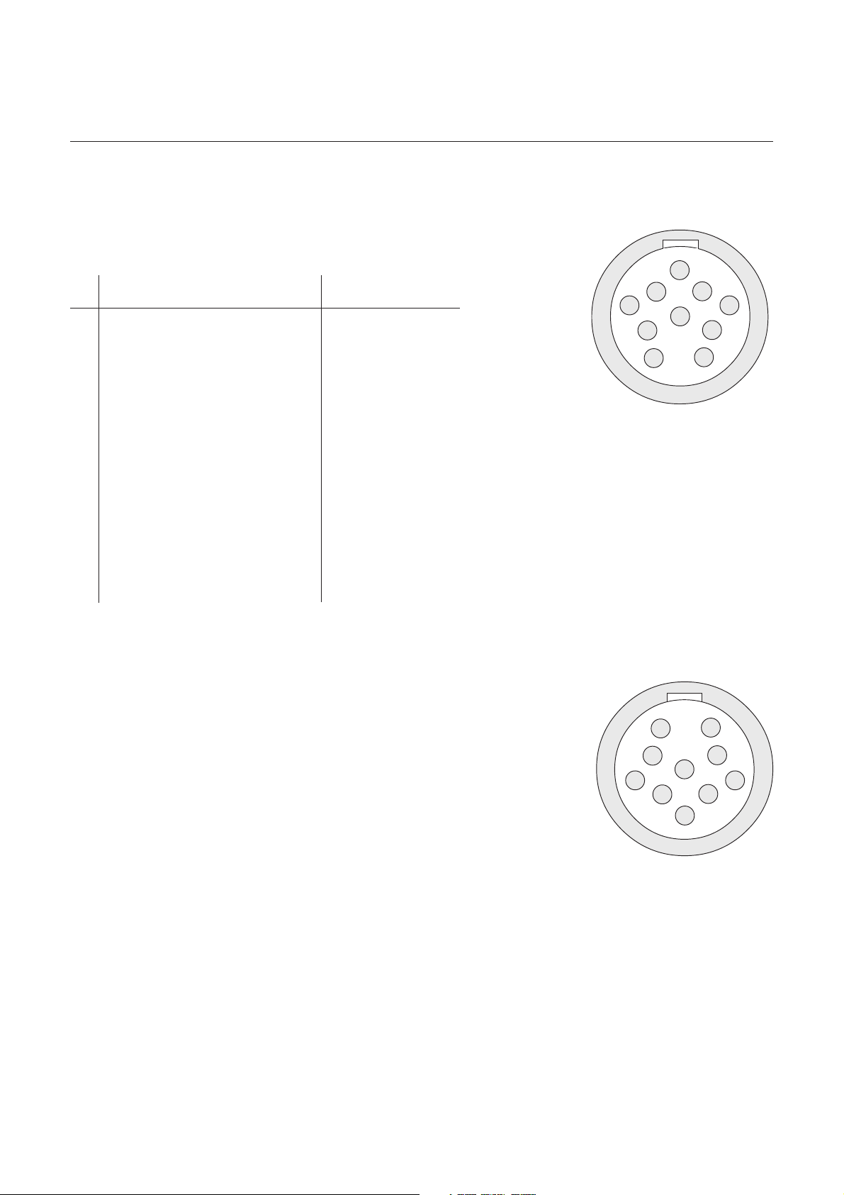
4.1.4 Socket Paddle 30344416
1 PACHARGE
2 PADISCHARGE
3 RECSTART
4 CODE
5 CODE
6 CODE
High Voltage / Pace / Apex
High Voltage/ Pace / Sternum
High voltage
Sternum
Top View
Electrode plug
Pacharge
Code
654
123
Padischarge
High voltage
Apex
Recstart
227 483 02-B SA(e)-98.05
Page 32

Marquette Hellige GmbH CardioServ V.4 Page 32
Servicing Instructions
227 483 02-B SA(e)-98.05
Page 33

Marquette Hellige GmbH CardioServ V.4 Page 33
Servicing Instructions
5. Block Diagram CardioServ VF/V4
Fuse
S
PCB Display
930 117 17
I
PCB Motor
388 010 56
Printhead
388 439 76
Membrane
F
H
Keypad
390 001 52
62
68
69
U
PCB Shielding
433 672 24
Mains Input
HOSI
HBACK
PCB
Digital
PRINT
PRINT
KEYB
ANA
12 V
J
930 ... ..
388 032 53
388 032 06
OM
A
PS
PCB
Analog
HV+
HV-
PAP
DIGI EKG
12 V
OUT
BAT
PACE-
PACE+
930 ... ..
303 445 43
B
A
C
PCB Power
B
Supply
930 118 46
Defi
Electrodes
P
303 441 25
ECG
R
Electrodes
303 440 29
+-
Battery
KL
CHU
Car-holder
Charger
D. E. F.
Option Input
RS 232
303 445 17
Loudspeaker
303 445 32
227 483 02-B SA(e)-98.05
PACE
Pacemaker
BEEP
Potential
separation
AH
PCB MP 204
D
Oximeter Board
930 117 26
B
SPO2 Input
B
303 443 57
Page 34

Marquette Hellige GmbH CardioServ V.4 Page 34
Servicing Instructions
227 483 02-B SA(e)-98.05
Page 35

Marquette Hellige GmbH CardioServ V.4 Page 35
Servicing Instructions
6. Assembly Instructions
General Information:
Before opening the CardioServ switch the instrument off, disconnect power cord plug, remove battery and implement ESD protection measures. Return replacement PCB in ESD
packaging only
Opening the instrument:
Undo the 9 screws on the bottom of the device, place upper case shell to the left next to the
instrument.
Removing the PCB Digital:
The PCB Digital is located in the upper shell. Disconnect the 50-pin flat strip cable and the 2pin 12-V power supply cord. The recorder, plugged into the lower case shell, can be removed
and the flat strip cable connected to the thermal-array printhead and motor disconnected.
Lay the upper shell face down, remove the screening plate fixed in place by a screw and 5
plastic catches. Remove the insulating card. Undo the 8 PCB Digital fastening screws (leave
the 4 display screws in place) and remove the rotating knob of the energy selector switch.
Carefully lift up the PCB and pull out the membrane keypad connector on the left. The PCB
Digital can now be removed along with the display screen.
Removing the display screen:
-Disconnect plug-in connector to display illumination.
-Carefully pull the zero power connector safety catch of the display-membrane keypad
connector upwards and disconnect membrane keypad lead.
- Remove the 4 display fastening screws
Removing the PCB Analog:
Disconnect 50-pin flat strip cable, connection cable to the battery, power supply unit and
PCB Digital. Detach connector to the ECG socket and disconnect connections to Defi socket.
Remove ECG amplifier cover with 3 screws and 2 plastic catches. Unscrew the 10 screws on
the PCB Analog (4 capacitors, 2 high-voltage oscillators) and 3 hexagonal columns.
227 483 02-B SA(e)-98.05
Page 36

Marquette Hellige GmbH CardioServ V.4 Page 36
Servicing Instructions
227 483 02-B SA(e)-98.05
Page 37

Marquette Hellige GmbH CardioServ V.4 Page 37
Servicing Instructions
7. Troubleshooting Hints
Device cannot be switched on during line-power operation:
- 230-V power supply via power supply unit OK ? Measure at connector CA.
- Connector 230-V plug to power supply unit OK ?
- Fuse in feed line and on power supply unit OK ?
- Lead line-power supply unit -- PCB Analog OK ?
- Lead PCB Analog -- PCB Digital (2-pin power supply 16V) OK ?
- Lead PCB Analog -- PCB Digital (50-pin control) plugged in correctly?
- 16 V on PCB Analog at connector ? no --> power supply unit defective or short-circuit
(power supply unit tackered)
- Fuse SI500 (16V) on PCB Digital OK ?
- Fuse SI502 (5V) on PCB Digital OK ?
- Device On Signal PWON_ present and 16V available on PCB Digital : yes --> Digital
defective
- PCB Analog or PCB Digital defective ?
Device cannot be switched on during battery operation:
- Battery charged?
- Lead battery contacts -- PCB Analog OK ?
- Fuse for battery on PCB Analog OK ?
- Connector battery contact and connector power supply PCB Digital confused
- Fuse SI500 (16V) , SI502 (5V) on PCB Digital OK ?
- PCB Analog defective ?
Device does not print out:
- Paper inserted correctly? (thermosensitive side facing up)
- Flat strip cable to printer OK ?
- Mechanical failure in paper transport, paper feed ?
- Without paper platin runs approx. 1 sec
- Flap not completely closed
- Print key on membrane keypad does not respond when pressed (perform key test)
- Does motor run ? or printhead voltage there ? or movement on the data lines to printhead
? no --> PCB Digital defective ?
Pacemaker mode disabled
- No +5V power supply on floating side
- Pacemaker cable not plugged in correctly
227 483 02-B SA(e)-98.05
Page 38

Marquette Hellige GmbH CardioServ V.4 Page 38
Servicing Instructions
No display on LCD
- Contrast poorly adjusted ? (change contrast)
- Contrast keys defective ? (perform key test)
- Connector for illumination or data OK ?
- Illumination defective ?
- Fuse SI500 (16V) , SI501(background illumination) , SI502 (5V) on PCB Digital OK ?
- Display defective ?
- PCB Digital defective ?
No ECG on display via ECG cable or paddles
- Connector to ECG socket OK ?
- Connector to paddles OK ?
- Lead PCB Analog -- PCB Digital (50-pin control ) OK ?
- ECG via paddles or ECG cable OK : --> PCB Analog defective
- PCB Analog or PCB Digital defective ?
Battery does not charge:
- Yellow LED must glow when battery is being charged
- Fuse SI501 on PCB Analog defective ?
- Check connector to battery
- Voltage on power supply unit under 16 V
Self-test:
F1 + F5 simultaneously to go to configuration and with Print print out the current error messages
In configuration with F3 + F4 key test and carry out printer adjustment (Print key)
In configuration with F3 + F5 restore default (factory setting)
Display test chessboard pattern at power up
Error in time base : The clock must be set once or PCB Digital defective
Error in energy storage : Adjust energy storage / measurement or PCB Analog defective
Error RAM, ROM, Display-RAM, permanent memory, watchdog : PCB Digital defective.
Error Charge or Discharge actuated (key sticking).
Troubleshooting hints for PCB SPO2
When the PCB SPO2 is inoperative or operates defectively check the 5V floating voltage.
The voltage must lie between 4.8-4.9V.
227 483 02-B SA(e)-98.05
Page 39

Marquette Hellige GmbH CardioServ V.4 Page 39
Servicing Instructions
7.1 Error Codes in the CardioServ Self-Test Screen
0002 : RAM error
0004 : RAM error
0008 : RAM error
0010 : ROM error
0020 : EEPROM error
0100 : Clock error
0200 : Charge key error
0400 : Discharge key error
0800 : Energy outside range
These errors can occur in combination : RAM + ROM : 0012
SpO2
No. 0 No a), internal, no error
No. 1 RAM b), MP204, RAM error
No. 2 ROM b), MP204, ROM error
No. 3 Data Link c), MP204, serial communication to SpO2 module is defective
No. 4 Command c), MP204, defective commands from CardioServ to SpO2
module
No. 5 Value c), MP204, defective values from CardioServ to SpO2 module
No. 6 Calibration e), MP204, calibration error
No. 7 Not used e), MP204, SpO2 is in calibration mode
No. 8 Calibr. request c), MP204, calibration request rejected by SpO2 module
No. 9 Communication c), MP204, defective commands from CardioServ to SpO2
module
No. 10 Over-current d), MP204, excessive sensor current identified
No. 11 Post Aver Time e), internal, Post Average Time (integration time setting not
adopted)
No. 12 Post Aver Time e), internal, Post Average Time (integration time scanning rate
not adopted)
No. 13 Defect e), internal, undefined error
a) no error, everything O.K.
b) SpO2 module no longer functions, replace SpO2 module
c) check connection from main board to the SpO2 module
d) replace sensor or cable and switch CardioServ off and then on again
e) switch CardioServ off and then on again
227 483 02-B SA(e)-98.05
Page 40

Marquette Hellige GmbH CardioServ V.4 Page 40
Servicing Instructions
227 483 02-B SA(e)-98.05
Page 41

Marquette Hellige GmbH CardioServ V.4 Page 41
Servicing Instructions
8. Adjustment Instructions
1
MP3/
R 504
R 505
R 506
R 507
AE/
34
MP1/
MP2/
AC/
1
1
AD/
1
AM/
6
1
AJ/
40
10
AK/
1
AG/
1
1
AB/
SI500
PCB Digital 388 032 06
PCB Digital 388 032 53
227 483 02-B SA(e)-98.05
SI502
SI502
1AH/16
1
AI/
1
AA/
40
Page 42

Marquette Hellige GmbH CardioServ V.4 Page 42
Servicing Instructions
Motor Adjustment on PCB Digital
What to adjust or to What to measure How to activate Where to turn? How much and What else to note?
check? with? testing mode? exact?
Adjust motor speed Flash at motor pinion 1) Call up configura- Speed selector Stroboscope Motor should be at
under small load with stroboscope tion (Press F1 + F5 R 506 frequency room temperature.
(recorder flap open) (LED). simultaneously) = 181.07 Hz The testing mode
on stationary motor 2) Call up key test terminates automatipinion. (Press F3+F4 keys When a square wave cally after a few
Adjust motor speed Compensation If the RPM changes
under normal load adjuster after compensation
(recorder flap closed) R 505 adjustment, this
and small load should be corrected
(recorder flap open) once more only
so that there is no with R521.
difference in RPM.
simultaneously) generator activated seconds. This can be
3) Press Print key by LED is used, a suppressed by
Speed selector low key ratio should pressing any key.
be observed.
227 483 02-B SA(e)-98.05
Page 43

Marquette Hellige GmbH CardioServ V.4 Page 43
Servicing Instructions
No Stroboscope Available: Motor Adjustment on PCB Digital
What to adjust or to What to measure How to activate Where to turn? How much and What else to note?
check? with? testing mode? exact?
Adjust motor
speed under
small load (recorder
flap open wide
enough so that
paper is just
transported)
Adjust motor speed
under normal load
(recorder flap
closed)
Remeasure grid
printout.
min. 200 mm
1) Call up configuration (Press F1 + F5
simultaneously)
2) Call up key test
(Press F3+F4 keys
simultaneously)
3) Press Print key
Speed selector
R506
Compensation
adjuster
R505
< 1%
Motor should be at
room temperature.
The testing mode
terminates automatically after a few
seconds. This can
be suppressed by
pressing any key.
The adjust-procedure
is complete when
the RPM is 25 mm/s
under small load and
normal load.
Heating Time Adjustment on PCB Digital
What to adjust or to What to measure How to activate Where to turn? How much and What else to note?
check? with? testing mode? exact?
Heating time
Connect oscilloscope
to MP2/1 and
MP1/1 (GND)
Press Print key in
main menu
Heating time
adjuster
R507
500µs +/- 1%
referred to 22°C
printhead temperature
Adjustment ensues at
25 mm/s.
Important: printhead
warms up during
printing
5-V Overvoltage Cutoff Threshold on PCB Digital
What to adjust or to What to measure How to activate Where to turn? How much and What else to note?
check? with? testing mode? exact?
5-V power supply
monitoring
Voltmeter. Input
impedance >=
1MOhm
Between MP3/1
and GND
R504
2,720V <1%
227 483 02-B SA(e)-98.05
Page 44

Marquette Hellige GmbH CardioServ V.4 Page 44
Servicing Instructions
Control of the Power Supply Voltages on PCB Digital
What to adjust or to What to measure Where to How much What else to note?
check? with? measure? and exact?
5-V power supply
+22-V power supply
-23-V power supply Voltmeter.
Voltmeter.
Voltmeter.
Between +5V
and GND
Between +22V
and GND (C504)
between -23V
and GND
5,0V +/-2%
+22V +/-5% Recorder stationary
-23V +/-5%
227 483 02-B SA(e)-98.05
Page 45

Marquette Hellige GmbH CardioServ V.4 Page 45
Servicing Instructions
PCB Analog
PCB Analog 303 445 (for Service)
PCB Analog 388 028 10R (for Production)
227 483 02-B SA(e)-98.05
Page 46

Marquette Hellige GmbH CardioServ V.4 Page 46
Servicing Instructions
Important Notice for Energy adjustmend on Pcb.Analog
In order to represent the actual charged Energy on the Display of the CardioServ, it is necessary to activate the following function .
1. Press together the key F1 and F 5 ⇒ the Function < Unit Configuration > is active
2. Press together the key F3 and F 4 ⇒ the Function < Key t -Test > is active
3. Press any key on the key pad
4. Press together the key F3 and F 4 ⇒ leave the Function < Key t -Test >
Now the Energy adjustment may to be started.
Note: In user mode the selected Energy is displayed within the allowed tolerance.
Energy Adjustment on PCB Analog
What to adjust or to What to measure How to activate Where to turn? How much and What else to note?
check? with? testing mode? exact?
Energy released in
50-ohm resistor
Adjust charging
time
Adjust display of
energy to be
released in 50ohm resistor
Adjust display of
energy released
Safety cut-off
Defi tester R534
Timer
Defi tester
Defi tester
Check screen
display
Check screen
display (50 ohms)
R525
R521
R523
R520
100J +-2J
8s
Energy displayed
in Defi tester +-2J
Energy displayed in
Defi tester +-2J
Attention! Do not alter
Turn R508 left to
minimum. Selector
switch to 100J
Defibrillate in Defi
tester
Starting from the
left adjust R512
Selector switch to
360J
Defibrillate in Defi
tester
Selector switch to
100J
Defibrillate in Defi
tester
Selector switch to
100J
Defibrillate in Defi
tester
Safety cut-off
adjustment in factory
only
Check all energy
levels
Defi tester
227 483 02-B SA(e)-98.05
R534, R521,
R523
Selected energy level
+-5% or 2J
Higher value
permissible
Adjust all energy
levels on energy
selector switch. If
required, correct
previous settings
Page 47

Marquette Hellige GmbH CardioServ V.4 Page 47
Servicing Instructions
EC Amplifier Adjustment on PCB Analog
What to adjust or to What to measure How to activate Where to turn? How much and What else to note?
check? with? testing mode? exact?
Offset EC amplifier
cable
Amplification EC
amplifier cable
Offset EC amplifier
paddles
Amplification EC
amplifier paddles
Optical scale
Optical scale
Optical scale
Optical scale
Display
Printer
Display
Printer
R501
R500
R524
R522
Baseline offset
< 1 mm
10 mm
+-0.5 mm
Baseline offset
< 1 mm
10 mm
+- 0.5 mm
Connect ECG pickup
with paddles
Amplitude 1 mV
Toggle amplification
between 0.5, 1 and 2
ECG pickup 1 mV
Toggle amplification between
0.5, 1 and 2
227 483 02-B SA(e)-98.05
Page 48

Marquette Hellige GmbH CardioServ V.4 Page 48
Servicing Instructions
227 483 02-B SA(e)-98.05
Page 49

Marquette Hellige GmbH CardioServ V.4 Page 49
Servicing Instructions
9. Technical Specifications CardioServ/CardioServ VF
The Technical Specifications section describes the technical data of the device valid
at the time of printing.
Operating modes
* manual (non-synchronized, synchronized)
* semiautomatic (VF)
* semiautomatic/button (VF)
* semiautomatic/dongle (VF)
Energy selection
adjustable, energy to be delivered into 50 ohms displayed digitally
* selectable energy levels, energy to be delivered into a 50-ohm resistance (max. energy of
50 joules for internal defibrillation):
2
5
7
10
20
30
50
100
150
200
300
360 joules
* possible deviation from selected energy below values specified by IEC
Energy storage
by means of capacitor, capacitor is charged from battery, from a 12-volt power source (emergency vehicle) or from the power line (95 to 240 V; 49 to 65 Hz); when capacitor charging is
terminated buzzer sounds:
* capacitor charging time for energy setting of 360 J:
from power line: typically 8 s
from fully charged battery: typically 8 s
from partially discharged battery: typically 10 s (15s max.),
measured at least 5 minutes after 15 shocks of 360 joules each
(for 200 joules typically 4 s)
227 483 02-B SA(e)-98.05
Page 50

Marquette Hellige GmbH CardioServ V.4 Page 50
Servicing Instructions
Defibrillation shock
capacitor discharge via induction coil (damped serial resonant circuit), pulse shape = a sinusoidal halfwave with decay period:
* pulse duration for an external resistance of 50 ohms approx. 4 ms, measured from the
beginning of the pulse to the intersection of the zero line and the inflection point of the
trailing pulse edge
* in synchronized mode the defibrillation shock is released within 30 ms of the R-wave
trigger
Discharge circuit
serial oscillating circuit in series with external resistance (patient):
* capacitance 32 µF
* inductance 26 mH
* equivalent resistance 6.5 ohms
Pulse output
isolated, no conductive connection with enclosure, open-circuit and short-circuit-proof
* isolation test voltage 8 kV DC, type CF according to IEC requirements
Safety discharge
capacitor discharge via internal load resistance:
* when the defibrillation shock is not triggered within 30 s after charging
* when the defibrillation shock is triggered, but the discharge circuit is interrupted, after
approx. 0.2 s
* immediately when reducing the selected energy during or after charging
* when the selected energy is not reached, after 32 s
* in the event of technical malfunctions
Test features
* pilot lamp for battery charging
* defibrillator test by discharging the stored energy into the internal 50-ohm load resistance;
3-digit display of the delivered energy
* warning on LCD when discharge circuit is interrupted (e.g., defibrillation paddle not ap-
plied)
* automatic defibrillator test on power up with display of error message, if applicable
Synchronization
with ECG signal of either polarity:
* min. ECG amplitude for reliable triggering approx. 0.5mV with QRS duration of 80 ms
227 483 02-B SA(e)-98.05
Page 51

Marquette Hellige GmbH CardioServ V.4 Page 51
Servicing Instructions
ECG signal input via paddles
ECG signal acquisition via defibrillator paddles, ECG trace displayed on LCD, automatic
switching to ECG electrodes when patient cable is connected; cardioversion both via ECG
patient cable and via paddles; differential input; isolated, class CF according to IEC, with
overvoltage protection
* input voltage range ±4 mV
* input impedance >1.5 Mohm
* max. polarization voltage ±1V
* frequency response 2.2 Hz to 20 Hz (-3 dB)
* common-mode rejection >80 dB
* patient leakage current: in normal condition <10 µA, insingle-fault condition <50 µA
* detection of pacing pulses
pulse duration dp >approx. 0.1ms <2.0ms
pace marker independent of polarity
pulse amplitude ap ±20 to ±700mV
reverse-current pulse a0 ±1mV
time constant t0 = 25 to 100 ms
ECG signal input via patient cable
via ECG electrodes, automatic switching to ECG electrodes when patient cable is connected;
cardioversion both via ECG electrodes and via paddles; differential input, symmetrically
referred to N, isolated, class CF according to IEC; 7 standard leads selectable via lead selector; input with overvoltage protection (defibrillation-proof):
* input voltage range ±4.4 mV for recorder,
±4 mV for display
* input impedance >2.5 Mohm for 10 Hz
* common-mode dynamic range ±3 V
* differential DC voltage compatibility ±1 V
* common-mode rejection (CMRR) R,L referred to N 65dB, N referred to chassis >110 dB
* QRS trigger (measured according to AAMI EC 13): trigger threshold 0.3 mV (for QRS
widths between 40ms and 70 ms and between 30 and 250 BPM)
* bandwidth .5 to 100 Hz
* patient leakage current: in normal condition <10 µA, insingle-fault condition <50 µA
* ground leakage current: in normal condition .5 mA, insingle-fault condition 1 mA
* voltage resistance referred to circuit reference 4 kV
227 483 02-B SA(e)-98.05
Page 52

Marquette Hellige GmbH CardioServ V.4 Page 52
Servicing Instructions
* detection of pacing pulses
pulse duration dp >approx. 0.1ms <2.0ms
pace marker independent of polarity
pulse amplitude ap ±20 to ±700mV
reverse-current pulse a0 ±1mV
time constant t0 = 25 to 100 ms
Signal display
backlit LCD, 2-channel erase bar mode, calibration pulse in left-hand corner (for ECG)
alphanumeric presentation of alarm messages, sensitivity, leads, systole blinker, alarm
limits, heart rate, energy and softkey labels
ECG freeze with simultaneous display of the current ECG and (for units with SpO
2
function) plethysmogram at a smaller scale
ECG trace 1.5 times larger than on recording: with a sensitivity of 1 cm/mV a 1-mV
signal has an amplitude of 1.5 cm on the display
* erase bar sweep speed 25 mm/s
* trace length in real-time mode 4.6 s
* display dimensions: 115 mm wide, 86 mm high
* resolution 320 x 240 pixels (pitch of .36 x .36 mm)
* displayed image can be rotated 180°
Signal transmission
signal input > amplification > signal sampling > AD conversion > digital
processing > LCD and recorder
* selectable sensitivity: .5-1-2 cm/mV (with max. sensitivity of 2 cm/mV a 1-mV input
signal is 2 cm in amplitude on the recorder and about 3 cm on the LCD), amplitude
limited to approx. ±2 cm on the recorder and approx. ±3 cm on the LCD
* signal sampling rate 1000 Hz at mains frequency of 50Hz, 1200 Hz at mains fre-
quency of 60Hz
ECG signal output (Option port)
* ECG lead shown on display
* 1V output signal for 1mV input signal (at 1cm/mV)
*U
max
±2V
* overall error < 3% (typical)
*RL 500W min.
* delay < 150 ms (not suitable for precise triggering)
9 = ECG
10 = chassis
227 483 02-B SA(e)-98.05
Page 53

Marquette Hellige GmbH CardioServ V.4 Page 53
Servicing Instructions
Systole check
* heart symbol flashing on the LCD
* QRS beep (can be disabled)
* AC line filter 50 Hz (60 Hz); interference elimination
* muscle filter
low pass filter with f
f
= 32 Hz (60 Hz mains)
lim
= 27 Hz (50 Hz mains)
lim
cut-off at 83/100 Hz
Heart-rate measurement
derivation of trigger pulses from the ECG of either polarity, adaptive trigger threshold, calculation of the average rate, storage of the result, 3-digit display on LCD, alarm limits to the left of
the reading:
* measuring range 15 to 300 BPM
* digit height of HR reading 7.5 mm
* digit height of alarm limits 2.5 mm
* min. amplitude for reliable triggering >.25 mV for ECG signal with a QRS duration of 80
ms
Alarm system
electronic release of alarm
* when the HR violates one of the set limits for at least 5 s: alarm tone sounds (can be
disabled), message Alarm, high HR or Alarm, low HR, recorder starts (if configured)
* when at least one of the selected electrodes drops off: audible signal (if patient cable is
plugged in), message Alarm, Electrode on display
* alarm limits adjustment range 15 to 300 BPM (not overlapping)
* digit height of alarm limits 2.5 mm
* keys to cancel alarm and to silence alarm tone
* softkeys to adjust alarm limits
* when set up for VF detection running in the background, alarm release can be enabled or
disabled
227 483 02-B SA(e)-98.05
Page 54

Marquette Hellige GmbH CardioServ V.4 Page 54
Servicing Instructions
Recording
delayed recording of the ECG stored in the signal memory (strip length 16 s, incl. 4-s history)
in the event of an alarm plus alphanumeric annotations on the paper margin:
heart rate
lead
filter
date
time
paper speed
cause of recording (defib, alarm, manual)
selected energy
delivered energy
sync mark
text (name of user/hospital/practice)
After the ECG recording, a patient ID sheet is printed indicating name, date of birth, user,
comments, date, time, energy and alarm limits.
Direct writing with rectangular coordinates using thermorecording technology (printhead with
electronically controlled thermal elements records on thermosensitive paper), baseline fixed
at the center of the space available for recording of the ECG trace, grid imprint, roll paper,
paper transport by electronically controlled DC motor, limited duration of transport
* number of recording channels 2
* paper width 55 mm
* roll diameter 60 mm max. (roll with 40 m of Marquette Hellige CONTRAST®)
* printhead resolution vertical 6 dots/mm, horizontal 24dots/mm
* paper speed 25 mm/s ±5%
* paper transport after both manual and automatic start 16s (incl. history of 4 s after auto-
matic recorder start)
To prevent damage to the printhead, use only the original Marquette Hellige CONTRAST
®
chart paper.
Memory
* storage of 40 ECG strips initiated by defibrillation or alarm with a length of 16 seconds
and a history of 4seconds each, incl. a full report
* storage of the 80 most recent actions (e.g., power on, power off, alarms, defibrillation
energy) incl. date and time
227 483 02-B SA(e)-98.05
Page 55

Marquette Hellige GmbH CardioServ V.4 Page 55
Servicing Instructions
SpO
2
* saturation: 0 to 100 %, in 1-% increments
* frequency: 0 to 250 BPM, in 1-BPM increments
* alarm limit: off, 15 to 100 %
* display of plethysmogram
* C-LOCK ECG synchronization
* integration time: 4, 8 and 12 seconds
* measuring accuracy: 70 to 100% ±2 digits
50 to 69% ±3 digits
pulse display 1.2% or ±1 BPM
Pacemaker
* operating modes:demand, fixed-rate
* pacing rate: 30 to 180 BPM
* pacing current: 0 to 200 mA (for 500 Ohms),
voltage up to 120 V
* pulse width: 40 ms
20 ms (for pacing rate of 155BPM and higher)
* pulse shape: monophase square-wave pulse
* error message Check Electrode when pacer output differs from set value (±20% or
±20mA)
Power
from the power line
* 95 V to 240 V, 49 Hz to 65 Hz
* power consumption at 230 V
during monitoring 160 mA
during capacitor charging 750 mA
* from a 12-Volt power source of the emergency vehicle
* from exchangeable, rechargeable NiCd batteries
* rated voltage 12 V
* rated capacity 1.4 Ah
* battery is charged while inserted in the unit
* charging time for depleted battery approx. 16 hours
227 483 02-B SA(e)-98.05
Page 56

Marquette Hellige GmbH CardioServ V.4 Page 56
Servicing Instructions
* operating time with a fully charged battery approx. 35 defibrillation shocks of 360 joules
each (into 50 ohms) or 2 hours of monitor operation (1.2 hours with pacemaker and SpO
measuring system)
Operational readiness
4 s after power up (incl. automatic selftest)
Operating position
any
Environment
Operation
under the following conditions regarded as normal:
* temperature between 0 and +40 °C
* rel. humidity between 30 and 95%, no condensation
* atmospheric pressure between 700 and 1060 hPa
2
Storage and transport
* temperature between -20 and +60 °C
* rel. humidity between 10 and 95%, no condensation
* atmospheric pressure between 500 and 1060 hPa
Dimensions
* width 432 mm
* height 172 mm
* depth 377 mm
Weight
* approx. 8 kg (incl. battery)
227 483 02-B SA(e)-98.05
Page 57

Marquette Hellige GmbH CardioServ V.4 Page 57
Servicing Instructions
10. Maintenance and Technical Inspection
Technical Inspections
Testing the operating and functional safety of the CardioServ is carried out according to the
checklists below.
They serve the experienced technician when inspecting the instrument. A knowledge of how
to operate the CardioServ in compliance with the operators manual is assumed.
The tests are based on the calibration devices described below. Where possible, the tests
should be conducted using the customers accessories to also detect any defective accessories automatically.
Using calibration devices other than those named below may require changes in the tests
and tolerance specifications.
10.1 General Information
The CardioServ is an instrument with an internal power source assigned to Protection Class I
and Class IIb ( MPG ).
The instrument is suitable for external and internal defibrillation (as well as cardioversion).
The heart rate is monitored with configurable alarm limits. Upgrade options include a transcutaneous pacemaker and / or SPO2 calibration module; the latter can also be monitored.
In addition, the CardioServ VF has the following operating modes:
- manual
- semi-automatic with the option to switch over to manual by pressing a key
- semi-automatic with the option to switch over to manual with the help of an encoding
module
- as a semi-automatic instrument
Caution!
CardioServ uses high voltage. The inspection should be referred to independent persons with adequate training and experience.
These inspections must be carried at least once a year.
227 483 02-B SA(e)-98.05
Page 58

Marquette Hellige GmbH CardioServ V.4 Page 58
Servicing Instructions
10.2 Testing Equipment
ECG simulator
Defitester
Safety tester, e.g., NSE
1X SPO2 simulator 408 610-001
1X SPO2 SpO2 sim. Hellige circular power
cord connector 223 417 01
1X Finger probe 701 240 21
1X Power cord for SpO2 sensor 303 443 58
Test adapter to measure pacing pulses 220 101 01
Dongle 303 445 15
227 483 02-B SA(e)-98.05
Page 59

Marquette Hellige GmbH CardioServ V.4 Page 59
Servicing Instructions
Recommended Test Equipment
- Safety Tester for measurements according to IEC 601.
- Testing connector according to the following drawings.
Testing connector for measuring patient leakage current
The following wiring of testing connectors is recommended for the technical inspection of
module input type BF (body floating) and type CF (cardiac floating).
The catalog numbers of the Marquette Hellige components are given below.
When making the connectors observe the following configurations:
The diagrams of the plug inserts in this document are always as viewed from the inside of
the connector shell.
- Testing connector for the temperature input
1 x 2-pin jack plug 91530000
1 x Telephone socket or 91534800
matching isolated plug connection for testing case
The two jack plug poles are short-circuited with one another and connected to the
telephone socket.
- Testing connector for ECG input
1* Connector 91541378
8
6
3
12
7
4
5
10* Contact pins 91541394
1* Telephone socket or 91534800
matching isolated plug connection for testing case
9
10
Short-circuit all 10 contact pins with one another and connect to
telephone socket.
- Testing connector for SaO2 input
1* Connector 91541871
9
10
8
6
3
1
7
4
5
2
7* Contact pins 91541394
1 * Telephone socket or 91534800
matching isolated plug connection for testing case
227 483 02-B SA(e)-98.05
6* 10 kohm resistor 92184443
Connect pin 10 directly to the telephone socket.
Connect pins 1,4,5,6,7,9 via 10 kohm resistor to telephone socket.
Page 60

Marquette Hellige GmbH CardioServ V.4 Page 60
Servicing Instructions
Measure patient leakage current on the Defi electrodes
The patient leakage current on the Defi electrodes is measured directly on each paddle.
10.3 Visual Check
Test instrument and accessories to ensure that
- fuse links have the rating proclaimed by the manufacturer
- safety labels and inscriptions on the device are clearly legible
- the mechanical condition will allow the device to be put to further use
- any soiling has no effect on safety of operation.
The defibrillator electrodes as well as handles and holder recesses must be free of any
cream residue.
The defibrillator electrodes, pacemaker cable, ECG cable , SPO2 cable and CardioServ
power cord should be checked for any visible external damage to the insulation and strain
relief.
10.4 Performance Check
10.4.1 Power-up Test
Switch the instrument on with the energy selector switch (turn rotary switch to first position
ECG).
A chessboard pattern appears on the display for about 2 seconds. A performance test follows
and the software release number is displayed. If the self-test is O.K., no error message appears on the screen. When error message occurs, see page 39 "Error Codes".
10.4.2 Key Test
Press the F1 and F5 keys simultaneously. The configuration screen appears. By pressing
the F3 and F4 keys simultaneously the key test screen appears in the selftest mode.
By pressing each key in turn, the function of the keys can be tested. The key pressed appears in the key test screen with its assigned function. This screen also provides self-test
information. The self-test screen also shows the software version, its checksum and the
results of the CardioServ self-test. The options built into this instrument are displayed alongside the results of the self-test, pacemaker version, VF, date, time and SPO2 version plus
error status.
227 483 02-B SA(e)-98.05
Page 61

Marquette Hellige GmbH CardioServ V.4 Page 61
Servicing Instructions
10.4.3 Printer Test
The printer is tested in the standard mode. Check that there is some paper andpress the
Print key. A manual printout will then be printed out at 25 mm/s.
Using a ruler check the printout grid. In the event of a deviation, reset the motor speed (for
details see p. 42 Motor Adjustment).
10.4.4 Energy Test
Connect defibrillation electrodes to Defi. The paddles must be locked in place in the Defi
holders.
Prerequisite for the following test < energy 360 joules in 9 seconds>
The Defi battery must be fully charged or the Defi must be connected to the mains with a
power cord.
Switch instrument on. Switch energy selector switch to 360 joules. Energy must be available
after approx. 9 seconds. Trigger energy charge operation by pressing the Charge Defi key in
the electrode handle.
As soon as the charge operation is complete a beep sounds. Release the defibrilla
tion pulse with the Charge Defi key and the Defib key within the next 30 s.
The values (tolerance range) for the energy released is given in the table below.
If an energy adjustment proves necessary, use the adjustment instructions given in the Servicing Instructions Manual.(Please refer to p 46 Energy Adjustment)
Energy selected Energy available/released Energy released
in CardioServ display in joulemeter
2 1-3 1-3
5 4-6 4-6
7 6-8 6-8
10 8-12 8-12
20 18-22 18-22
30 28-32 27-33
50 45-55 45-55
70 65-75 63-77
100 95-105 92-108
150 145-155 140-160
200 190-210 188-212
300 290-310 285-315
360 350-370 340-380
227 483 02-B SA(e)-98.05
Page 62

Marquette Hellige GmbH CardioServ V.4 Page 62
Servicing Instructions
10.4.5 Pacemaker Test (Without pacemaker testing adapter)
Caution: During the pacemaker test the energy selector switch may be set to the ECG position only. Do not actuate the Defib and Charge keys.
Connect trunk cable for disposable adhesive defibrillation electrodes Part No. 223 346 01 to
the Defi.
Short-circuit middle contacts 2 and 3.
Connect 500 ohm resistor between contacts 1 and 4.
Switch pacemaker on Defi on and select operating mode Fix.
Using the +mA ; -mA key select any pulse amperage.
Using the +P/min ; -P/min key select any frequency.
Pulse width Demand, Fix: 40 ms
> 155 P/min 20 ms
Using the oscilloscope measure the drop in voltage across the measuring resistor.
Calculate pulse amperage according to Ohms Law I = U/R
(Pulse amperage = measured voltage / measuring resistor 500 ohms).
Calculated pulse amperage must correspond to setting in Defi display. Error message Check
electrodes appears when pulse current deviates from configured value (± 20% or ± 20 mA)
Switch pacemaker on Defi on and select operating mode Demand.
Using the +mA ; -mA key select any pulse amperage.
Using the +P/min ; -P/min key select frequency of 60 pulses.
Using the ECG simulator set frequency to below 60 pulses. The pacemaker pulses should be
measured as described above.
Using the ECG simulator set frequency to above 60 pulses. In this case the pacemaker will
be reset. The pacemaker pulses do not need to be measured.
227 483 02-B SA(e)-98.05
Page 63

Marquette Hellige GmbH CardioServ V.4 Page 63
Servicing Instructions
10.4.6 Pacemaker Test (with Marquette Hellige testing adapter)
The Marquette Hellige testing adapter offers two possibilities for pacemaker testing.
1. Pacing pulse detection via LED
2. Pacing pulse measurement with an oscilloscope.
Caution: During the pacemaker test the energy selector switch may be set to the ECG position only. Do not actuate the Defib and Charge keys.
Connect testing adapter to CardioServ.
Switch pacemaker on Defi on and select operating mode Fix.
Using the +mA ; -mA key select any pulse amperage.
Using the +P/min ; -P/min key select any frequency.
Pulse width Demand, Fix: 40 ms
> 155 P/min 20 ms
Using the oscilloscope measure the drop in voltage across the measuring resistor.
Calculate pulse amperage according to Ohms Law I = U/R
(Pulse amperage = measured voltage / measuring resistor 500 ohms).
Calculated pulse amperage must correspond to setting in Defi display. Error message Check
electrodes appears when pulse current deviates from configured value (± 20% or ± 20 mA)
Switch pacemaker on Defi on and select operating mode Demand.
Using the +mA ; -mA key select any pulse amperage.
Using the +P/min ; -P/min key select frequency of 60 pulses.
Using the ECG simulator set frequency to below 60 pulses. The pacemakerpulses should be
measured as described above.
Using the ECG simulator set frequency to above 60 pulses. In this case the pacemaker will
be reset. The pacemaker pulses do not need to be measured.
227 483 02-B SA(e)-98.05
Page 64

Marquette Hellige GmbH CardioServ V.4 Page 64
Servicing Instructions
10.4.7 SPO2 Performance Check
Connect SPO2 power cord 701 240 31 to a SPO2 probe on the Defi.
Since there is no affordable SPO2 simulator currently available, the SPO2 test should be
performed by the tester himself.
Connect finger probe to test subject (tester). The SPO2 readings and the plethysmogram
appear after a few seconds.
Simulator settings
Test the SpO2 parameter with the Marquette SpO2 simulator as follows:
- Switch simulator power switch to off.
- Connect connector cable up between simulator and CardioServ monitor.
- Set SpO2 to 95.5% using the white Nellcor scale.
- Set pulse rate to 100 bpm.
- Select mode on Nellcor.
- Activate power switch.
Monitor settings on CardioServ
Activate pulse frequency display by pressing F5 (next), followed by switching to (HR Source
Pulse) with F1 (HR Source Pulse).
Displaying waveforms and parameter readings
- A sine wave SpO2 waveform should appear on the screen.
- An SpO2 parameter reading of 92%-95% should be displayed.
- The pulse rate displayed should lie between 96 and 104 bpm.
Testing display accuracy of SpO2 and pulse rate
Check displayed values on the LCD screen using the following simulator settings:
Simulator value SpO2 Value displayed
95.5% 92% - 99%
90.6% 87% - 94%
85.5% 82% - 89%
Simulator value pulse rate Value displayed
227 483 02-B SA(e)-98.05
70 bpm 66 bpm - 74 bpm
100 bpm 96 bpm - 104 bpm
160 bpm 155 bpm - 165 bpm
Page 65

Marquette Hellige GmbH CardioServ V.4 Page 65
Servicing Instructions
Activate interference test on the simulator by pressing key and keep it pressed, the SpO2
value must remain displayed on the screen.
Disconnect the SpO2 plug from the monitor. The message No Sensor appears, accompanied by an intermittent audible alarm signal, provided the alarm is enabled.
Press (F4) button, alarm is silenced.
Connect up finger probe and check it is working correctly.
10.4.8 ECG Test
Connect the electrode cable to the Defi. Use a standard ECG signal generator to generate
ECG signals. Use either a 3-lead trunk cable 223 287 01 or a 5lead trunk cable 223 400 11.
Switch Defi to monitor mode. The ECG and the heart rate adjusted on the ECG simulator
appear on the display. The upper and lower limits should be tested to ensure they are enabled. The error messages when electrodes become detached should also be checked. The
error message <Electrode error> appears on the left-hand side of the display. It is important
to ensure that the ECG lead is selected so that the corresponding electrode is tested. In the
case of the paddles lead the error message <Electrode error> appears on the screen when
the paddles are taken out of their holders on the CardioServ.
10.4.9 Cardioversion Test
Connect the electrode cable to the Defi. Use a standard ECG signal generator to generate
signals. Use either a 3-lead trunk cable 223 287 01 or a 5-lead trunk cable 223 400 11.
Set energy selector switch to any energy setting. Actuate SYNC key on the Defi. The SYNC
function should now appear in the display. Defi paddles are locked into place in the CardioServ holder.
Charge energy by pressing the Charge Defib key. After charging is complete actuate Charge
Defib and Trigger Defib keys. Triggering is effected by the Zpeak of the beat. Afterwards,
the function Cardioversion is automatically reset.
10. 4.10 Option Socket Input Test
The option socket input can be tested with the dongle No. 303 445 15 in the configuration. If
you can enable the operating mode Semi-automatic/Dongle in the configuration (press F1
and F5 keys simultaneously) of semi-automatic defibrillators, this indicates that this function
is O.K. Furthermore, the 1-volt ECG signal is still available at this option socket input. With
an incoming ECG signal this can be measured with the oscilloscope.
227 483 02-B SA(e)-98.05
Page 66

Marquette Hellige GmbH CardioServ V.4 Page 66
Servicing Instructions
10.5 Battery
A battery charge check can only be performed in the battery service unit Part No. 101 128
01. This tests takes at least 2 hours, max. 3 hours. The service manual for the battery service
unit can be ordered under Part No. 227 454 77.
If no battery service unit is available, the battery should be replaced every 2 years.
Battery Maintenance
Proper maintenance of NiCd batteries is essential and considerably promotes their proper
performance. Routine preventive maintenance should be carried out by qualified service
technicians on a regular basis (recommended interval: 30 days). If batteries are repeatedly
partially discharged, the resulting "memory effect" max dramaticaly reduce the battery capacity.
This effect can be efficiently minimzied by regular conditioning. If the capacity of a relatively
new battery is drastically reduced, the battery max be reconditioned by repeated charging
and discharging.
Monthly Battery Maintenance (Conditioning) and Checks
1. Disconnect CardioServ from the power line and discharge fully charged battery in the
monitoring mode. To do so, set energy selector switch to (SpO2 sensor not connec-
ted) and wait until device switches off.
2. Check how long it takes before battery is depleted. If the time is less than 1.8 hours, the
battery is too old or improperly maintained and should be replaced.
3. Recharge the battery. This will take 16 hours.
Rechargeable batteries require special maintenance and continued checks to assure they
function in emergency situations. It is normal for batteries of this type to selfdischarge when
not in use.
227 483 02-B SA(e)-98.05
Page 67

Marquette Hellige GmbH CardioServ V.4 Page 67
Servicing Instructions
11. Safety Analysis Test
11.1. General introduction
The suggested Safety Analysis Tests refer to the international standard IEC 601-1.
The tests are generally performed with Safety Testers, on most of them, the measuring circuits according IEC 601 are already implemented.
The following is a general description of the tests to be performed. For the handling of your
Safety Tester follow the user manual.
The tests may be performed under normal ambient conditions of temperature, humidity and
pressure and with line voltage.
The leakage currents correspond to 110 % of rated voltage for the tested unit. Most Safety
Testers take this into account,
otherwise the measured values have to be calculated.
11.2 Recommended Test Equipment
- Safety Tester for measurements according to IEC 601.
- Testing connector according to the following description.
11.3 Protective Earth Resistance Test
The power cord is to be included in the protective earth resistance test.
This test determines whether the device has a power ground fault.
- The protective earth resistance from power connector to any protective earth connected
exposed conductive part is measured.
- Specs. of test circuit: AC current source 50 Hz/60 Hz of at least 10 A up to 25 A with
limited output voltage of 6 V.
- If resistance is greater than 100 mOhm, the unit fails this test.
227 483 02-B SA(e)-98.05
Page 68

Marquette Hellige GmbH CardioServ V.4 Page 68
Servicing Instructions
11.3.1 Leakage Current Measurement
To perform the suggested measurements, the unit under test has to be separated from any
interconnection to a system. If the unit is part of a system, extended tests according to IEC
601-1-1 have to be performed. The following diagram shows the
Measuring Circuit [M] required for leakage current. The reading in mV corresponds to µA
(leakage current). The Safety Testers generally work with this Measuring Circuit [M] and the
displayed values are already converted to leakage current.
10 k
1 k
0,015 µF
mV
Measuring
instrument/
Calibrator
(
R
>1 M Ω)
i
11.3.2 Enclosure Leakage Current Test
This test is performed to measure leakage current from chassis to ground during normal
conditions (N.C.) and single fault conditions (S.F.C.).
In all cases, the leakage current is measured from any exposed conductive parts to ground,
the unit under test has to be switched on and off.
Connect the unit under test to your Safety Tester.
- During normal conditions (N.C.), referring to the electrical diagram, measurements have to
be done under the following conditions:
* Polarity switch Norm and RVS
* GND switch GND closed
* S1 closed and open
227 483 02-B SA(e)-98.05
Page 69

Marquette Hellige GmbH CardioServ V.4 Page 69
Servicing Instructions
- During single fault conditions (S.F.C.), referring to the electrical diagram, the measure-
ments have to be done under the following conditions:
* Polarity switch NORM and RVS
* GND switch GND open
* S1 closed
Test has failed if the measured values are greater than:
N.C. S.F.C
100 µA 500 µA
300 µA (U.L. requirements)
Electrical Diagram for Enclosure Leakage Current Test
Safety Tester
S1
[M]
NORM/RVS
GND
POWER CORD
UNIT
UNDER
TEST
Probe to exposed
chassis
HIGH
LOW
GND
POWER CORD
11.3.3 Patient Leakage Current Test
This test performs a leakage current test under single fault conditions (S.F.C.) depending on
domestic power outlet with 115 or 230 V AC as source into the floating inputs.
The following signals have a separate floating input and have to be tested separately.
ECG from ECG Input socket
ECG from Paddels
SPO2
In all cases, the leakage current is measured from input jack of unit under test to ground. The
measurement ground point is the left-hand contact on the underside of the CardioServ.
227 483 02-B SA(e)-98.05
Page 70

Marquette Hellige GmbH CardioServ V.4 Page 70
Servicing Instructions
For testing the floating ECG input ,a patient cable, with all leads connected together, is used.
For testing the floating input from Paddles, the test is measured on each Defipaddles.
For testing the floating input from SPO2 , test plugs are used.
Connect the unit under test to your Safety Tester.
- Referring to the electrical diagram, measurements have to be done under the following
conditions:
* Polarity switch NORM and RVS
* GND switch GND closed
* S1 closed
Test has failed if the measured values are greater than 50 mA at ECG Input and SPO2
Input.
Test has failed if the measured values are greater than 100 mA at Defipaddles.
Electrical Diagram for Patient Leakage Current Test
Safety Tester
S1
NORM
[M]
RVS
GND
PATIN JACK
POWER CORD
UNIT
UNDER
TEST
patient cable
or test plug
HIGH
LOW
GND
POWER CORD
R
For protection of the test person, the following values of resistor R may be used:
Typ BF 22 kOhm (120 to 130 V)
47 kOhm (220 to 240 V)
Typ CF 100 kOhm (220 to 240 V)
227 483 02-B SA(e)-98.05
Page 71

Marquette Hellige GmbH CardioServ V.4 Page 71
Servicing Instructions
12. Spare Parts Lists
CardioServ VF Version 4.x
CardioServ Version 4.x
Operation Manuals
227 453 03 Servicing Instructions
227 446 21 Operating Manual german CardioServ VF
227 446 22 Operating Manual engl. CardioServ VF
227 446 23 Operating Manual fren. CardioServ VF
227 446 25 Operating Manual ital. CardioServ VF
227 446 26 Operating Manual span. CardioServ VF
227 446 28 Operating Manual russ. CardioServ VF
227 446 29 Operating Manual ital. Esaote VF
Defi Paddles
217 304 03 Defibrillation Electrode, external, with recorder start, for CardioServ
217 308 01 Electrode Lead f.Defi-El.internal without contact insert, for SCP 913
926 074 97 Handle
Keypads VF
390 001 52 Keypad with Pacemaker ESAOTE/international
390 001 68 Keypad without pacemaker ESAOTE/international
390 001 62 Keypad with pacemaker USA
390 001 69 Keypad without pacemaker USA
Keypads manual
390 001 56 Keypad without pacemaker, international
390 001 57 Keypad with pacemaker, international
390 001 58 Keypad without pacemaker ESAOTE
390 001 59 Keypad with pacemaker ESAOTE
390 001 60 Keypad without pacemaker USA
390 001 61 Keypad with pacemaker USA
Recorder
384 015 81 Exchange Recorder preman. f. CardioServ
303 439 76 Thermal printhead
303 434 78 Transportation roller
918 083 49 Motor 18 V~
227 483 02-B SA(e)-98.05
Page 72

Marquette Hellige GmbH CardioServ V.4 Page 72
Servicing Instructions
480 159 46 Gear 10 mm diameter
480 159 47 Gear 24 mm diameter
480 159 48 Gear 40 mm diameter
388 010 56 Pcb. Motor
432 522 30 Flap, Recorder
430 517 84 Sticker in Flap
Printed circuit boards for Version 4.x
303 445 43 Pcb. Analog (389 004 22)
389 004 22 Exchange Pcb. Analog (303 445 43)
388 032 53 Pcb.Digital without pacemaker (389 004 22)
389 004 26 Exchange Pcb.Digital without pacemaker (388 032 53)
388 032 06 Pcb.Digital with pacemaker (389 004 26)
389 004 25 Exchange Pcb.Digital with pacemaker (388 032 06)
930 117 26 Pcb. SPO2
303 445 32 Speaker
903 449 88 Capacitor
Housing
303 445 14 Upper shell VF
303 445 22 Upper shell USA VF
430 519 28 Sticker operation information englih
430 519 29 Sticker operation information french
430 519 30 Sticker operation information italia
430 519 31 Sticker operation information spanish
430 519 32 Sticker operation information russian
303 442 85 Upper shell
303 443 61 Upper shell Esaote
303 444 46 Upper shell USA
430 517 93 Sticker operation information, engl
430 517 94 Sticker operation information, fren
430 518 09 Sticker operation information, ital
430 518 10 Sticker operation information spani
430 518 11 Sticker operation information russi
432 522 08 Lower Shell
430 518 05 Sticker Attention, high voltage...
430 518 06 Sticker Attention, high voltage...
430 518 07 Sticker Attention, high voltage...
430 518 12 Sticker Attention high voltage...
227 483 02-B SA(e)-98.05
Page 73

Marquette Hellige GmbH CardioServ V.4 Page 73
Servicing Instructions
430 518 13 Sticker Attention high voltage...
430 518 14 Sticker Attention high voltage...
504 657 54 Contact > Station
432 522 27 latch
432 522 35 Filler Plug
924 017 22 Foot
482 035 19 Knob for energy selector
482 035 21 Knob for energy selector (Esaote)
923 096 69 Mounting Base
829 074 11 Scotch mount, white
In-/Output connector
303 442 99 ECG Inputconnector completely wired for CardioServ
303 443 57 SPO2 Inputconnector kompletely wired for CardioServ
303 445 17 Inputconnector option Dongle
303 444 16 Electrode coupling for paddles
915 417 95 Mains plug, 3 wire
303 444 22 Charge Socket for 12 V (Option)
841 202 28 Screw
803 083 02 Nut
804 177 06 Washer
Power supply
930 117 97 Switching power supplies
908 122 28 Fuse block
912 084 53 Fuse fast 5.0A UL
303 440 30 Battery Pack for SCP 910/913/915/922
12 V / 1,2 Ah
LCD Display
930 117 17 LCD Graphic Display
Ambulance Holder for CardioServ
504 658 18 Case
504 658 21 Insulating Device
416 118 28 CONTACT SPRING
504 658 23 Recording Upper
427 338 70 BOLT
504 658 22 Recording Lower
504 658 20 Handle
227 483 02-B SA(e)-98.05
Page 74

Marquette Hellige GmbH CardioServ V.4 Page 74
Servicing Instructions
402 236 14 SOCKET
914 326 43 Pushbuttom switch
427 338 69 ROD
388 011 38 Pcb. 12 V- option
227 483 02-B SA(e)-98.05
Page 75

Marquette Hellige GmbH CardioServ V.4 Page 75
Servicing Instructions
13. Accessories: Car holder
CardioServ Car-Holder 202 307 01
The car-holder secures the CardioServ during ambulance transport. In this holder the
CardioServ is supplied with power from the 12-volt ambulance power supply system.
CardioServ Wall Holder 202 307 02
The wall holder secures the CardioServ when not in use. It is identical to the car-holder,
except that it does not have any electronics to charge the battery or supply power to the
device.
CardioServ Charging Unit 205 106 01
The charging unit serves to supply power in the CardioServ during vehicle transport. The
CardioServ is supplied with power from the 12-volt vehicle power supply system. Using this
charging unit requires equipping the CardioServ with the charging socket 303 444 22.
227 483 02-B SA(e)-98.05
Page 76

Marquette Hellige GmbH CardioServ V.4 Page 76
Servicing Instructions
Installation Instructions for the CardioServ Mounting System 202 307 01
* First of all, connect the mounting system to the
12-V power supply system of the ambulance (cable
aperture on the underside of the mounting system,
see terminal diagram).
* Connect the positive terminal (+12 V) to the free
contact of the fuse holder (4.8-mm sleeve
enclosed).
Connect earth (0 V) to the corresponding contact of
the terminal block (4.8-mm sleeve enclosed).
Please use the enclosed adhesive fastening base
and the cable tie to fix the connection cables.
Observe the following points when connecting the
mounting system:
- the negative terminal of the ambulance power
supply must be connected to earth,
- the positive lead must be protected with a 10
Amp fuse (slow blow) and
- the lead diameter must be adequate.
* The mounting system has 4 bore holes both at the
top and bottom edges, allowing it to be mounted to
the ambulance in a vertical or horizontal position
(take care that the mounting system is flush against
the wall of ambulance; in the vertical position the
wider part with the cable aperture must face down!)
(see Fig. 1).
* Replace the 4 rubber feet of CardioServ with the
metal feet enclosed. When screwing down the
metal feet, please note that they have a recess on
one side for the screw head.
* Use the appropriate type of screws for attachment
of the metal feet: If the CardioServ unit is equipped
with metal bushings, please use the fillister head
screws DIN 912 M 4 x 12; if there is no metal
bushing but only a hole, please use Plastite screws
4 x 16.
* Please be sure to use the red feet (angular groove)
at the bottom, i.e., on the side with the contacts.
(See Fig. 2).
unlock here
bottom
Figure 1
227 483 02-B SA(e)-98.05
red
Figure 2
* If required, you may attach the enclosed rubber feet
on top of the metal feet.
* Mount the CardioServ by first inserting the feet at
the bottom, then by introducing the feet at the top.
* To remove the device press on the latches (top
center).
Page 77

Page 78

Page 79

Page 80

Page 81

Page 82

Page 83

Page 84

Page 85

Marquette Hellige GmbH
Not equipped in Version :
1)
2)
3)
4)
5)
Revision-No
REVISIONS
Index
Date / Name
A04
DRAWN
APPROVED
ISSUED
D-79007 Freiburg
F67211
Date / Name
21.03.96/SNA
11.07.96/SNA
M&E/ALLGEIER
388 032 03 P
LPL DEFI_HWDONGLE
PCB DEFI_HWDONGLE
Sheet:
11
of
[1997, 7, 1, 3]
Page 86

Page 87

Marquette Hellige GmbH
Not equipped in Version :
1)
388 032 05
2)
3)
4)
5)
Revision-No
REVISIONS
Index
Date / Name
A03
DRAWN
APPROVED
ISSUED
D-79007 Freiburg
F67213
Date / Name
11.04.96/SNA
05.12.96/HWM
M&E/MIKLOSS
388 032 05 P
LPL CServ4_ANALOG
PCB CServ4_ANALOG
$USER_CAD_A/f67213/design
Sheet:
of
111
[1996, 12, 6, 6]
Page 88

Marquette Hellige GmbH
Not equipped in Version :
1)
388 032 05
2)
3)
4)
5)
Revision-No
REVISIONS
Index
Date / Name
A03
DRAWN
APPROVED
ISSUED
D-79007 Freiburg
F67213
Date / Name
11.04.96/SNA
05.12.96/HWM
M&E/MIKLOSS
388 032 05 P
LPL CServ4_ANALOG
PCB CServ4_ANALOG
$USER_CAD_A/f67213/design/e_ecg_input
Sheet:
of
11
2
[1996, 12, 6, 6]
Page 89

Marquette Hellige GmbH
Not equipped in Version :
1)
388 032 05
2)
3)
4)
5)
Revision-No
REVISIONS
Index
A
Date / Name
14.04.97/JOK202 826
A03
DRAWN
APPROVED
ISSUED
D-79007 Freiburg
F67213
Date / Name
11.04.96/SNA
05.12.96/HWM
M&E/MIKLOSS
388 032 05 P
LPL CServ4_ANALOG
PCB CServ4_ANALOG
$USER_CAD_A/f67213/design/e_ecg_filter
Sheet:
of
113
[1996, 12, 6, 6]
Page 90

Marquette Hellige GmbH
Not equipped in Version :
1)
388 032 05
2)
3)
4)
5)
Revision-No
REVISIONS
Index
A
Date / Name
15.07.97/JOK202 957
A03
DRAWN
APPROVED
ISSUED
D-79007 Freiburg
F67213
Date / Name
11.04.96SNA
05.12.96/HWM
M&E/MIKLOSS
388 032 05 P
LPL CServ4_ANALOG
PCB CServ4_ANALOG
$USER_CAD_A/f67213/design/e_ecg_control
Sheet:
of
114
[1996, 12, 6, 6]
Page 91

Marquette Hellige GmbH
Not equipped in Version :
1)
388 032 05
2)
3)
4)
5)
Revision-No
REVISIONS
Index
Date / Name
A03
DRAWN
APPROVED
ISSUED
D-79007 Freiburg
F67213
Date / Name
11.04.96/SNA
05.12.96/HWM
M&E/MIKLOSS
388 032 05 P
LPL CServ4_ANALOG
PCB CServ4_ANALOG
$USER_CAD_A/f67213/design/high_voltage
Sheet:
of
115
[1996, 12, 6, 6]
Page 92

Marquette Hellige GmbH
Not equipped in Version :
1)
388 032 05
2)
3)
4)
5)
Revision-No
REVISIONS
Index
Date / Name
A03
DRAWN
APPROVED
ISSUED
D-79007 Freiburg
F67213
Date / Name
11.04.96/SNA
05.12.96/HWM
M&E/MIKLOSS
388 032 05 P
LPL CServ4_ANALOG
PCB CServ4_ANALOG
$USER_CAD_A/f67213/design/d_ekg_input
Sheet:
of
116
[1996, 12, 6, 6]
Page 93

Marquette Hellige GmbH
Not equipped in Version :
1)
388 032 05
2)
3)
4)
5)
Revision-No
202 826 14.04.97/JOK
REVISIONS
Index
A
Date / Name
A03
DRAWN
APPROVED
ISSUED
D-79007 Freiburg
F67213
Date / Name
11.04.96/SNA
05.12.96/HWM
M&E/MIKLOSS
388 032 05 P
LPL CServ4_ANALOG
PCB CServ4_ANALOG
$USER_CAD_A/f67213/design/d_ekg_filter
Sheet:
of
711
[1996, 12, 6, 6]
Page 94

Marquette Hellige GmbH
Not equipped in Version :
1)
388 032 05
2)
3)
4)
5)
Revision-No
REVISIONS
Index
Date / Name
A03
DRAWN
APPROVED
ISSUED
D-79007 Freiburg
F67213
Date / Name
11.04.96/SNA
05.12.96/HWM
M&E/MIKLOSS
388 032 05 P
LPL CServ4_ANALOG
PCB CServ4_ANALOG
$USER_CAD_A/f67213/design/d_ekg_control
Sheet:
of
8
11
[1996, 12, 6, 6]
Page 95

Marquette Hellige GmbH
Not equipped in Version :
1)
388 032 05
2)
3)
4)
5)
Revision-No
REVISIONS
Index
Date / Name
A03
DRAWN
APPROVED
ISSUED
D-79007 Freiburg
F67213
Date / Name
11.04.96/SNA
05.12.96/HWM
M&E/MIKLOSS
388 032 05 P
LPL CServ4_ANALOG
PCB CServ4_ANALOG
$USER_CAD_A/f67213/design/charge_control
Sheet:
of
119
[1996, 12, 6, 6]
Page 96

Marquette Hellige GmbH
Not equipped in Version :
1)
388 032 05
2)
3)
4)
5)
Revision-No
202 826
202 957
REVISIONS
Index
A
B
Date / Name
14.04.09/JOK
A03
DRAWN
APPROVED
ISSUED
D-79007 Freiburg
F67213
Date / Name
11.04.96/SNA15.07.97/JOK
05.12.96/HWM
M&E/MIKLOSS
388 032 05 P
LPL CServ4_ANALOG
PCB CServ4_ANALOG
$USER_CAD_A/f67213/design/charge_generator
Sheet:
of
1110
[1996, 12, 6, 6]
Page 97

Marquette Hellige GmbH
Not equipped in Version :
1)
388 032 05
2)
3)
4)
5)
Revision-No
REVISIONS
Index
Date / Name
A03
DRAWN
APPROVED
ISSUED
D-79007 Freiburg
F67213
Date / Name
11.04.96/SNA
05.12.96/HWM
M&E/MIKLOSS
388 032 05 P
LPL CServ4_ANALOG
PCB CServ4_ANALOG
$USER_CAD_A/f67213/design/conn_intf
Sheet:
of
1111
[1996, 12, 6, 6]
Page 98

Page 99

Page 100

HELLIGE GMBH
AENDERUNGEN
Aend. -Nr. Index Datum/Name
A04
gez.
gepr.
Entw.
Postfach 728
D-79007 Freiburg
F67214
Datum/Name
02.10.96/SNA
388 032 06 P
LPL. CServ4_DIGITAL
PCB CServ4_DIGITAL
 Loading...