

Page 1

Wide Conversion Lens System
LN-11S1A
Page 2
The lightning flash with arrowhead symbol within an equilateral triangle is
intended to alert the user to the presence of uninsulated “dangerous voltage”
within the product’s enclosure that may be of sufficient magnitude to constitute a
risk of electric shock to persons.
The exclamation point within an equilateral triangle is intended to alert the user
to the presence of important operating and maintenance (servicing) instructions
in the literature accompanying the product.
CAUTION
RISK OF ELECTRIC SHOCK
DO NOT OPEN
CAUTION: TO REDUCE THE RISK OF ELECTRIC SHOCK,
DO NOT REMOVE COVER (OR BACK)
NO USER-SERVICEABLE PARTS INSIDE
REFER SERVICING TO QUALIFIED SERVICE PERSONNEL
LA LAME LA PLUS LARGE DE LA FICHE DANS LA BORNE
WARNING
TO REDUCE THE RISK OF FIRE OR ELECTRIC SHOCK,
DO NOT EXPOSE THIS PRODUCT TO RAIN OR MOISTURE.
CAUTION: TO PREVENT ELECTRIC SHOCK, MATCH WIDE BLADE OF
PLUG TO WIDE SLOT, FULLY INSERT.
ATTENTION: POUR ÉVITER LES CHOC ÉLECTRIQUES, INTRODUIRE
CORRESPONDANTE DE LA PRISE ET POUSSER JUSQU’AU FOND.
IMPORTANT SAFETY
INSTRUCTIONS
READ BEFORE OPERATING EQUIPMENT
This product was designed and manufactured to
meet strict quality and safety standards. There are,
however, some installation and operation precautions
which you should be particularly aware of.
1. Read these instructions.
2. Keep these instructions.
3. Heed all warnings.
4. Follow all instructions.
5. Do not use this apparatus near water.
6. Clean only with dry cloth.
7. Do not block any ventilation openings. Install
in accordance with the manufacture’s
instructions.
8. Do not install near any heat sources such as
radiators, heat registers, stoves, or other
apparatus (including amplifiers) that produce
heat.
9. Do not defeat the safety purpose of the
polarized or grounding-type plug. A polarized
plug has two blades with one wider than the
other. A grounding type plug has two blades
and a third grounding prong. The wide blade
or the third prong are provided for your
safety. If the provided plug does not fit into
your outlet, consult an electrician for
replacement of the obsolete outlet.
10. Protect the power cord from being walked on
or pinched particularly at plugs, convenience
receptacles, and the point where they exit
from the apparatus.
11. Only use attachments/accessories specified
by the manufacturer.
12.
NOTE:
This equipment has been tested and found to
comply with the limits for a Class B digital device,
pursuant to Part 15 of the FCC Rules. These limits
are designed to provide reasonable protection
against harmful interference in a residential
installation. This equipment generates, uses and can
radiate radio frequency energy and, if not installed
and used in accordance with the instructions, may
cause harmful interference to radio communications.
However, there is no guarantee that interference will
not occur in a particular installation. If this equipment
does cause harmful interference to radio or
television reception, which can be determined by
turning the equipment off and on, the user is
encouraged to try to correct the interference by one
or more of the following measures:
- Reorient or relocate the receiving antenna.
- Increase the separation between the
equipment and receiver.
- Connect the equipment into an outlet on a
circuit different from that to which the receiver
is connected.
- Consult the dealer or an experienced radio/TV
technician for help.
NOTE:
Changes or modifications not expressly approved
by the party responsible for compliance could void
the user’s authority to operate the equipment.
This Class B digital apparatus complies with
Canadian ICES-003.
Cet appareil numérique de la Classe B est
conforme à la norme NMB-003 du Canada.
DECLARATION OF CONFORMITY
U.S. Responsible Party: Marantz America, Inc.
100 Corporate Drive,
Mahwah, NJ, 07430, U.S.A.
TEL: 201-762-6500
Type of Product:
Model:
Wide Conversion Lens System
LN-11S1A
This device complies with Part 15 of the FCC rules.
Operation is subject to the following conditions: (1) This
device may not cause harmful interference, and (2) this
device must accept any interference received, including
interference that may cause undesired operation.
Unplug this apparatus during lightning
storms or when unused for long periods of
time.
Refer all servicing to qualified service
personnel. Servicing is required when the
apparatus has been damaged in any way,
such as power-supply cord or plug is
damaged, liquid has been spilled or objects
have fallen into the apparatus, the apparatus
has been exposed to rain or moisture, does
not operate normally, or has been dropped.
13.
Additional Safety Information!
s !PPARATUS SHALL NOT BE EXPOSED TO DRIPPING OR
splashing and that no objects filled as vases,
shall be placed on the apparatus.
WARNINGS
s $ONOTREMOVETHECOVERFROMTHEEQUIPMENT
s $O NOT INSERT ANYTHING INTO THE EQUIPMENT
through the ventilation holes.
s $ONOTHANDLETHEMAINSCORDWITHWETHANDS
s $ONOTCOVERTHEVENTILATIONWITHANYITEMSSUCH
as tablecloths, newspapers, curtains, etc.
s .O NAKED FLAME SOURCES SUCH AS LIGHTED
candles, should be placed on the equipment.
s .O OBJECTS FILLED WITH LIQUIDS SUCH AS VASES
shall be placed on the equipment.
s 4HEEQUIPMENTSHALLBEINSTALLEDNEARTHEPOWER
supply so that the power supply is easily accessible.
s -AKE SURE THE !# POWER CORD IS FIRMLY
connected into the AC IN socket.
LN_080724U3N2
Page 3

ENGLISH
ESPAÑOL
IT ALIANO
WARRANTY
For warranty information, contact your local Marantz
distributor.
RETAIN YOUR PURCHASE RECEIPT
Your purchase receipt is your permanent record of a
valuable purchase. It should be kept in a safe place
to be referred to as necessary for insurance purposes
or when corresponding with Marantz.
IMPORTANT
When seeking warranty service, it is the responsibility of
the consumer to establish proof and date of purchase.
Your purchase receipt or invoice is adequate for such
proof.
FOR U.K. ONLY
This undertaking is in addition to a consumer’s
statutory rights and does not affect those rights in
any way.
FRANÇAIS
GARANTIE
Pour des informations sur la garantie, contacter le
distributeur local Marantz.
CONSERVER L’ATTESTATION D’ACHAT
L’attestation d’achat est la preuve permanente
d’un achat de valeur. La conserver en lieu sur pour
s’y reporter aux fins d’obtention d’une couverture
d’assurance ou dans le cadre de correspondances
avec Marantz.
IMPORTANT
Pour l’obtention d’un service couvert par la garantie,
il incombe au client d’établir la preuve de l’achat
et d’en corroborer la date. Le reçu ou la facture
constituent des preuves suffisantes.
GARANTIA
Para obtener información acerca de la garantia
póngase en contacto con su distribuidor Marantz.
GUARDE SU RECIBO DE COMPRA
Su recibo de compra es su prueba permanente de
haber adquirido un aparato de valor, Este recibo
deberá guardarlo en un lugar seguro y utilizarlo
como referencia cuando tenga que hacer uso del
seguro o se ponga en contacto con Marantz.
IMPORTANTE
Cuando solicite el servicio otorgado por la garantia
el usuario tiene la responsabilidad de demonstrar
cuándo efectuó la compra. En este caso, su recibo
de compra será la prueba apropiada.
DEUTSCH
GARANTIE
Bei Garantiefragen wenden Sie sich bitte an Ihren
Marantz-Händler.
HEBEN SIE IHRE QUITTING GUT AUF
Die Quittung dient Ihnen als bleibende Unterlage
für Ihren wertvollen Einkauf Das Aufbewahren der
Quittung ist wichtig, da die darin enthaltenen Angaben
für Versicherungswecke oder bei Korrespondenz mit
Marantz angeführt werden müssen.
WICHTIG!
Bei Garantiefragen muß der Kunde eine Kaufunterlage
mit Kaufdatum vorlegen. Ihren Quittung oder
Rechnung ist als Unterlage ausreichend.
GARANZIA
L’apparecchio è coperto da una garanzia di buon
funzionamento della durata di un anno, o del periodo
previsto dalla legge, a partire dalla data di acquisto
comprovata da un documento attestante il nominativo
del Rivenditore e la data di vendita. La garanzia sarà
prestata con la sostituzione o la riparazione gratuita
delle parti difettose.
Non sono coperti da garanzia difetti derivanti da
uso improprio, errata installazione, manutenzione
effettuata da personale non autorizzato o, comunque,
da circostanze che non possano riferirsi a difetti di
funzionamento dell’apparecchio. Sono inoltre esclusi
dalla garanzia gli interventi inerenti l’installazione e
l’allacciamento agli impianti di alimentazione.
Gli apparecchi verranno riparati presso i nostri Centri
di Assistenza Autorizzati. Le spese ed i rischi di
trasporto sono a carico del cliente.
La casa costruttrice declina ogni responsabilità per
danni diretti o indiretti provocati dalla inosservanza
delle prescrizioni di installazione, uso e manutenzione
dettagliate nel presente manuale o per guasti dovuti ad
uso continuato a fini professionali.
Page 4
CE MARKING
English
The LN-11S1A is in conformity with the
EMC directive and low-voltage directive.
Français
Le
LN-11S1A
EMC et à la directive sur les basses
tensions.
Español
El
LN-11S1A
normas EMC y las relacionadas con baja
tensión.
Deutsch
Da s Model l LN-11S1A entspric ht den
EMC-Richtlinien und den Richtlinien für
Niederspannungsgeräte.
Italiano
Il LN-11S1A è conforme alle direttive CEE
ed a quelle per i bassi voltaggi.
est conforme à la directive
está de acuerdo con las
English
WARNINGS
- Do not remove the cover from the equipment.
- Do not insert anything into the equipment through the
ventilation holes.
- Do not handle the mains cord with wet hands.
- Do not cover the ventilation with any items such as
tablecloths, newspapers, curtains, etc.
- No naked flame sources, such as lighted candles,
should be placed on the equipment.
- No objects filled with liquids, such as vases, shall be
placed on the equipment.
- The equipment shall be installed near the power
supply so that the power supply is easily accessible.
- Make sure the AC power cord is firmly connected into
the AC IN socket.
Français
AVERTISSEMENTS
- Ne pas essayer de retirer le boîtier de l’appareil.
- Ne rien insérer dans l’appareil par les orifices de
ventilation.
- Ne pas manipuler le cordon d’alimentation avec les
mains mouillées.
- Ne pas recouvrir les ouïes de ventilation avec un
objet quelconque comme une nappe, un journal, un
rideau, etc.
- Ne placer aucune source de flamme nue, comme
une bougie allumée, sur l’appareil.
- Aucun objet rempli de liquide, un vase par exemple,
ne doit être placé sur l’appareil.
- L’appareil sera installé près de la source
d’alimentation, de sorte que cette dernière soit
facilement accessible.
- Assurez-vous que le cordon d’alimentation secteur
est fermement branché dans la prise AC IN.
Español
ADVERTENCIAS
- No extraiga la tapa del equipo.
- No introduzca nada en el interior del equipo a través
de los orificios de ventilación.
- No maneje el cable de alimentación con las manos
mojadas.
- No cubra la ventilación con objetos como manteles,
periódicos, cortinas, etc.
- No deben colocarse sobre el equipo elementos con
fuego, por ejemplo velas encendidas.
- No se deben colocar sobre el aparato recipientes
que contengan líquidos, como por ejemplo jarrones.
- El equipo se instalará cerca de la fuente de
alimentación de manera que resulte fácil acceder a
ella.
- Asegúrese de que el cable de alimentación CA está
bien conectado al enchufe AC IN.
Deutsch
WARNHINWEISE
- Die Abdeckung nicht vom Gerät abnehmen.
- Keine Gegenstände durch die Belüftungsschlitze
stecken.
- Das Netzkabel nicht mit feuchten oder nassen
Händen anfassen.
- Decken Sie die Lüftungsöffnungen nicht mit einem
Tischtuch, einer Zeitung, einem Vorhang usw. ab.
- Es dürfen keine Gegenstände mit offener Flamme,
wie etwa brennende Kerzen, auf dem Gerät
aufgestellt werden.
- Auf das Gerät dürfen keine mit Flüssigkeiten gefüllte
Behälter, wie etwa eine Vase, gestellt werden.
- Das Gerät sollte in der Nähe einer Netzsteckdose
aufgestellt werden, damit es leicht an das Stromnetz
angeschlossen werden kann.
- Vergewissern Sie sich, dass das Netzkabel sicher in
die Buchse AC IN eingeführt ist.
Italiano
AVVERTENZE
- Non rimuovere il coperchio dell’apparecchio.
- Non introdurre oggetti all’interno dell’apparecchio
attraverso i fori di ventilazione.
- Non toccare il cavo di alimentazione con le mani
bagnate.
- Non coprire le fessure di ventilazione con tovaglie,
giornali, tende od oggetti analoghi.
- Non posare sull’apparecchio sorgenti di fiamme
scoperte quali candele accese.
- Non mettere sull’apparecchiatura alcun contenitore
di liquido, come ad esempio dei vasi.
- L’apparecchio va installato in prossimità della fonte
di alimentazione, in modo che quest’ultima sia
facilmente accessibile.
- Verificare che il cavo di alimentazione c.a. sia
collegato saldamente alla spina AC IN.
LN_080724U3N2
A NOTE ABOUT RECYCLING
This product’s packaging materials are
recyclable and can be reused. This product
and the accessories packed together are the
applicable produ ct to the WEE E directive
except batteries.
Please dispose of any materials in accordance
with your local recycling regulations.
When discarding the unit, comply with your
local rules or regulations.
Batteries should never be thrown away or
incinerated but disposed of in accordance with
your local regulations concerning chemical
wastes.
Page 5

CONTENTSINTRODUCTION
ABOUT THIS USER’S GUIDE
Before mo un ting th e LN -11S1 A, be sure to
thoroughly read the projector’s user’s guide and
decide on the mounting location.
A Marantz ceiling mount kit, MOUNT20, is required
if you will be using a Marantz VP11 or VP15 series
projector suspended from the ceiling. Be sure to
use an EXT10 to adjust the suspension height.
This User’s Guide serves as a setup guide that
describes how
EXT10, and mount the LN-11S1A.
For details on the space required for mounting, refer
to the figure showing the movable range at the end
of this guide.
to assemble the MOUNT20 and
IMPORTANT
Note:
The lens used in this product is a finely crafted,
precision optical device. It may be scratched or
even damaged from physical contact with objects
of any type.
Such contact and/ or imp roper handling must
therefore be avoided. Please note before use that
scratches caused by the user, whether intentional
or accidental, and damage to the lens due to
other external causes
warrantee.
Do not connect the AC/DC adapter supplied with the
anamorphic lens system to the lens slider or power
outlet until a projector (VP-11/VP-15), anamorphic
lens system (LN-11S1A), and bracket (MOUNT20/
EXT10) are completely mounted.
For information on other connections, refer to the
user’s guide for the device that is to be connected
to the LN-11S1A anamorphic le
To avoid accidentally scratching the lens surface
during mounting, hundle the lens with the most
careful attention.
The LN-11S1A lens slider uses a special motor and
several types of gears. If water or foreign matter
enters the LN-11S1A lens slider, damage to the
equipment or fire may result. If water or foreign
matter should enter the unit, immediately unplug
the power cord of the AC adap
Customer Service Center.
are outside the scope of the
ns system.
ter and contact our
If the LN-11S1A lens slider was moved by hands,
it might cause failure. Do not move the lens slider
by hands.
A Phillips-head screwdriver, hexagon wrench, and
spanner are required in order to assemble the LN11S1A, EXT10, and MOUNT20.
If you look into the lens during projection, light will
enter your eyes, possibly resulting in eye pain and/
or problems of vision.
During cleaning, unplug the power cor
adapter from the power outlet. For safety, always
unplug the power cord from the power outlet
at times when the unit will not be used for an
extended period, such as when you are out or on
vacation.
d of the AC
BEFORE USE
NOTE ON ASSEMBLY
Securely attach the anamorphic lens, lens slider, and
base plate using the provided metal screws.
NOTE ON MOUNTING
Even when attaching this unit to the projector, be
sure to use the specified screws and to attach the
unit securely. Also, the anamorphic lens moves left
and right.
Take care that there are no obstacles within the
range of motion of the lens.
Special skill and experience are required when
mounting the projector and this unit to a ceiling.
When mounting, please consult your dealer.
BEFORE USE ...............................................................................................................................................2
CHECKING THE UNIT AND SUPPLIED ACCESSORIES ...........................................................................................................2
NAMES OF PARTS .....................................................................................................................................2
BASIC OPERATION ...................................................................................................................................3
TURNING THE POWER ON ...........................................................................................................................................................3
TURNING THE POWER OFF ..........................................................................................................................................................3
CONTROLLING THE UNIT USING A TRIGGER INPUT SIGNAL .............................................................................................. 3
USING VP-11 OR VP-15 SERIES TRIG. 2 OUTPUT JACK ......................................................................................................... 3
CONCERNING CONNECTORS AND CABLES ............................................................................................................................4
ADVANCED OPERATION .......................................................................................................................... 5
USING A PROGRAMMABLE REMOTE CONTROLLER .............................................................................................................5
NOTES WHEN SIMULTANEOUSLY USING +12 V TRIGGER INPUT AND REMOTE CONTROLLER ................................. 5
FIXING THE ANAMORPHIC LENS POSITION............................................................................................................................5
SETUP ..........................................................................................................................................................5
SETUP PROCEDURE ....................................................................................................................................................................... 6
EXT10 ASSEMBLY ........................................................................................................................................................................... 6
PREPARING THE LN-11S1A .......................................................................................................................................................... 7
ASSEMBLING THE MOUNT20 .....................................................................................................................................................7
MOUNTING THE LN-11S1A (ON THE CEILING) ........................................................................................................................ 9
MOUNTING THE LN-11S1A (ON THE FLOOR) .........................................................................................................................10
MOUNTING THE LN-11S1A LENS .............................................................................................................................................10
CONNECTING THE LN-11S1A.....................................................................................................................................................10
ADJUSTING THE LN-11S1A LENS .............................................................................................................................................11
TROUBLESHOOTING...............................................................................................................................12
OTHERS .....................................................................................................................................................12
PROJECTION DISTANCE CHART FOR VP-11 AND VP-15 PROJECTORS ........................................................................... 12
SPECIFICATIONS & DIMENSIONS ............................................................................................................................................ 13
BEFORE USENAME OF PARTS
BASIC
OPERATION
ADVANCED
OPERATION
SETUP
TROUBLESHOOTING
OTHERS
1
Page 6
NAMES AND
FUNCTIONS
BEFORE USE NAMES OF PARTS
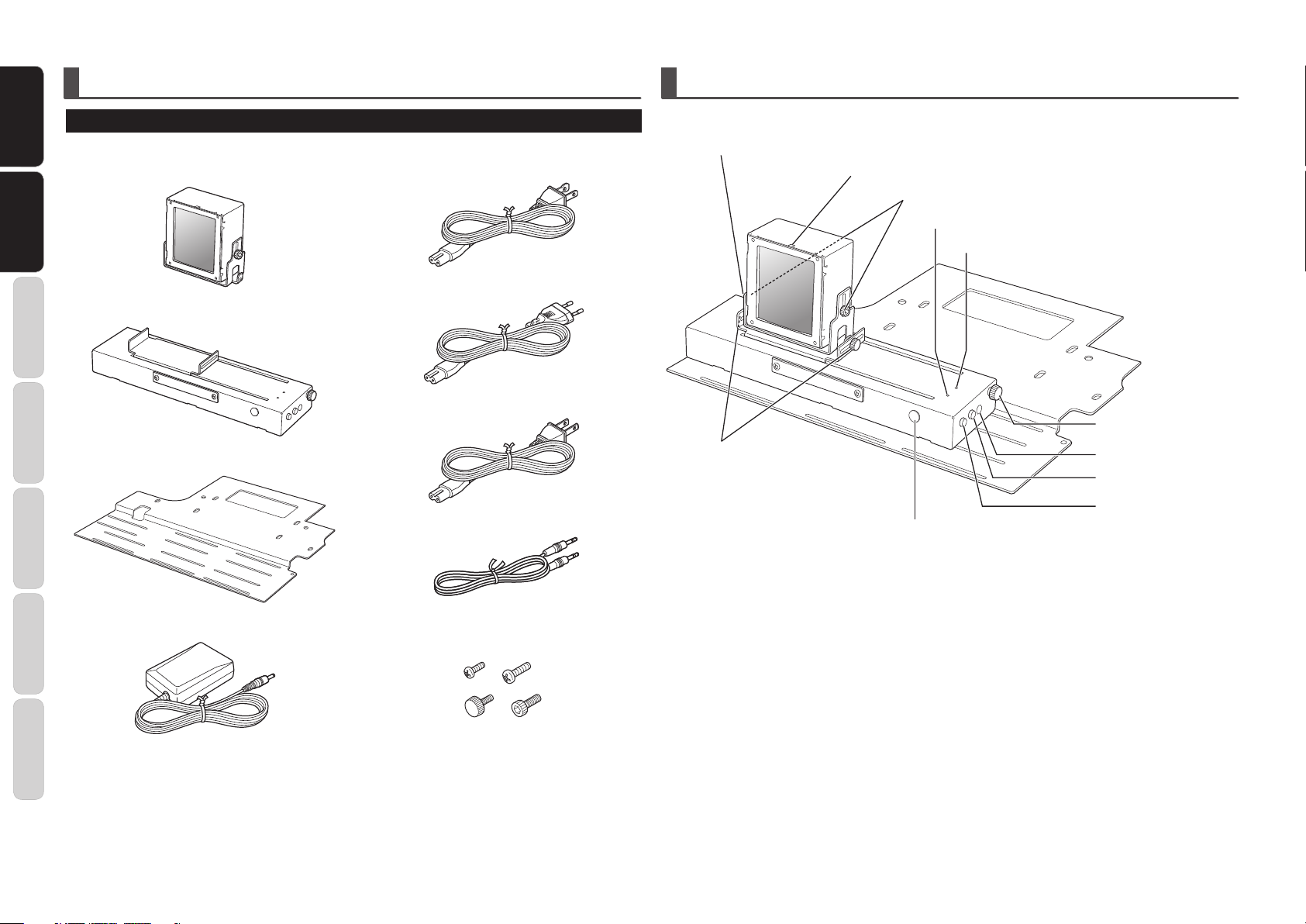
CHECKING THE UNIT AND SUPPLIED ACCESSORIES
Before use, check that the main unit and supplied accessories given below are assembled.
• Anamorphic lens x 1
NAME OF PARTS
• AC power cord (for U.S.A.) x 1
Focus adjustment screw (Page. 11)
Lens center mark
Height/tilt adjustment screw (Page. 10)
POWER ON indicator (Page. 3)
Trigger signal input indicator (Page. 3)
OPERATION
BASIC
• Lens Slider x 1
OPERATION
ADVANCED
• Base plate x 1
SETUP
• AC power cord (for Europe) x 1
• AC power cord (for Japan) x 1
• Trigger cable
Anamorphic lens back/forth
adjustment screw (Page. 10)
Remote control receiver (Page. 4)
Anamorphic lens left/right
adjustment screw (Page. 10)
+5 V DC jack (Page. 3)
Trigger signal input jack
(Page. 3)
Trigger signal output jack
(Page. 13)
TROUBLESHOOTING
• AC/DC adapter x 1
OTHERSBEFORE USE NAME OF PARTS
• Mounting screws (machine screw (M3 x 8) x
6, hexagon head bolt (M8 x 10) x 2, decorative
screws (M3 x 8) x 2)
• Washers x 2 (for 3-mm screws x 2, for 8-mm
screws x 2)
• Spring washers x 2
• User’s guide x 1
• Warranty card
U.S.A. x 1
Canada x 1
Japan x 1
2
Page 7

BASIC OPERATION
Standard 1
Auto Power Off
Trigger 2 Full
Trigger 2 Normal
Trigger 2 Zoom
Disable
Off
Off
Off
Trigger 2 V-stretch On
Trigger 2 Through Off
Reset Lamp Life
Reset All
Remote Control
Picture Adjust
Fine Menu 1
Fine Menu 2
Input Signal
RGB/HD Adjust
Display
OSD/Blanking
Config.
HDMI
TURNING THE POWER ON
Plug the AC cable of the AC/DC adapter into a power
outlet and plug the output plug into the DC jack of
the unit. The unit’s power turns on and the POWER
ON indicator on the top panel lights blue.
TURNING THE POWER OFF
To turn the unit’s power off, unplug the plug of the
AC/DC adapter from the DC jack. The unit’s power
turns off and the POWER ON indicator goes out.
Note:
Do not turn the unit’s power off while the anamorphic
lens is in motion. Doing so may result in damage to
equipment. If you will not be using the unit for an
extended period of time, be sure to unplug the AC/
DC adapter from the power outlet.
CONTROLLING THE UNIT USING
A TRIGGER INPUT SIGNAL
When 12 V DC is input to the +12 V TRIGGER IN
jack, the anamorphic lens moves to the operating
position (Refer to Figure 2) and trigger signal input
indicator on the top panel lights blue.
When 12 V DC is not input to the +12 V TRIGGER
IN jack, the anamorphic lens moves to the opposite
end from the operating position (Refer to Figure 1)
and trigger s
Note:
Do not move the LN-11S1A lens slider by hand. If
the lens slider was moved by hands, it might cause
failure.
ignal input indicator goes out.
Figure 1 Figure 2
USING VP-11 OR VP-15 SERIES
TRIG. 2 OUTPUT JACK
USING VP-11 OR VP-15 SERIES TRIG. 2 OUTPUT JACK
Trigger cable
LN-11S1A +12 V TRIGGER IN jack
Connect the TRIG. 2 output jack of VP-11 series or
VP-15 series to the +12V TRIGGER IN jack of the
lens slider.
Display the projector’s setup menu and set Trigger 2
V-stretch to On and turn all other settings Off. (Refer
to Figure 3)
Figure 3
When V-stretch is set for the projector’s aspect
mode, 12 V DC is automatically output from the
TRIG. 2 output jack and the anamorphic lens moves
to the operating position. (Under the settings given
above, 12 V DC is not output from the TRIG. 2
output jack in other aspect modes.)
For example, set the projector as described above.
If a movie having 2.35:1 cinemascope size is input
from HDMI1
and viewed under “full” aspect mode,
a black band will appear at the top and bottom of the
screen. Now, change the aspect mode to V-stretch.
The black bands at the top and bottom of the screen
will disappear, and the movie will be displayed at a
16:9 aspect ratio that fills the screen. At the same
time, 12 V DC is output from TRIG. 2 output jack, the
anamorphic lens moves in front of the projector
’
lens (operating position), and you can view the
movie at the correct aspect ratio of 2.35:1.
BEFORE USENAME OF PARTS
BASIC
BASIC
OPERATION
OPERATION
ADVANCED
OPERATION
s
SETUP
TROUBLESHOOTING
OTHERS
3
Page 8

BEFORE USE NAME OF PARTS
+12V DC
(Trigger Control)
N/C
Ground
INPUT
V-MUTE
ENTER
MENU
ASPECT
FULL
CINEMA
VCR MODE
BLACK LEVEL
PATTERN
BLACK
NOR ZOOM THRU
INFO.
C1 C2 SG1
H1 H2 VG2
A1
A2 RGB G3
STD DYN
I
M
A
G4
THTR
COMP.1 COMP.2 S-VIDEO USER
HDMI 1HDMI 2 VIDEO
AUX 1
BLANKING
AUX 2
RC-11VPS1
REMOTE CONTROLLER
ON
STANDBY
IRIS LAMP
C.TEMP GAMMA
B1 OFFB3B2
C1 C2 S G1
H1 H2 V G2
A1
A2 RGB G3
STD DY N G4
THTR
COMP.1 COMP.2 S-VIDEO USER
HDMI 1 HDMI 2 VIDEO
AUX 1 AUX 2
ON
STANDBY
IRIS LAMP
C.TEMP GAMMA
BASIC OPERATION
CONCERNING CONNECTORS
AND CABLES
The +12 TRIGGER IN/OUT jacks on the LN-11S1A
are used to input/output signals that move the
anamorphic lens into the operating position and
return it to standby position. Either a 3.5-mm
monaural mini-plug or 3.5-mm stereo mini-plug can
be used.
OPERATION
OPERATION
BASIC
BASIC
OPERATION
ADVANCED
A remote controller is not packaged with this unit.
This unit is controlled using the remote controller
supplied with a VP-11 or VP-15 series projector.
SETUP
TROUBLESHOOTING
OTHERS
4
TRIGGER CONNECTOR
REMOTE CONTROL
OPERATING RANGE OF REMOTE CONTROLLER
The operating range for a remote controller and this
unit is shown in the figure below.
30˚30˚
5m
Notes:
• Donotallowdirectsunlightorstronglight,such
as from inverter fluorescent lighting, to strike the
remote control receiver. The remote controller
may become inoperational.
• Notethatuseofa remote controllermayresult
in the unintended operation of other equipment
controlled using infrared signals.
• Theunitcannotbecontrolledremotelyifthereis
an obstacle between the remote controller and the
remote control receiver.
•Donotplaceobjectsontopoftheremotecontroller.
This may result in continuous depression of
buttons, causing batteries to be consumed.
REMOTE CONTROL CODE
Not only is it possible to control this unit using the
remote controller (AUX1 and AUX2) of a VP-11
series or VP-15 series projector, but it is also
possible to control this unit using a programmable
remote controller (such as an RC9001 or RC2001).
Commands used to control this unit are given in the
table on the right. For details, refer to page 5 under
“
ADVANCED OPERATION.
RC5
Command
00 56 15
00 62 01
00 56 20
00 62 02
Moves the anamorphic lens to the
operating position.
Moves the anamorphic lens to the
operating position.
Moves the anamorphic lens to the
non-operating position.
Moves the anamorphic lens to the
non-operating position.
”
Operation
CONTROLLING THE UNIT USING A REMOTE CONTROLLER
This unit can be controlled using a VP-11 or VP-15
series remote controller or programmable re
controller. Refer to Figure 4.
Press the AUX1 button on the VP-11 or VP-15 series
remote controller and the anamorphic lens moves
to the operating position (Refer to Figure 2). Press
the AUX2 button on the VP-11 or VP-15 series
remote controller and the anamorphic lens moves
to the opposite end from the operating position
(Refer to Figure 1).
Push to slide in Push to slide out
Figure 4
mote
CLEANING
The anamorphic lens used with this unit is a specially
coated, precision optical product.
If dust attaches to the lens surface, blow it off using
a blower dedicated to cleaning camera lenses. For
dirt attached to the lens, blow away dust attached
to the lens surface using a blower, and gently wipe
the lens using a soft cloth such as a cleaning cloth
or cloth for cleaning eyeglasses. If the
is noticeably dirty, wipe the dirt away using a soft
cloth for cleaning lenses dampened with a cleaner
for use with plastic lenses.Then, finish by wiping
the lens in the same manner with a new, soft cloth.
Take care because dirt may re-attach to the lens if
the lens is polished using the same cloth used to
wipe the dirt away.
Note:
Never use alcohol or benzene, thinner, acid/alkaline
cleaning agents, cleaners including polishing
agents, or chemically treated wiping cloth as they
may damage the lens surface.
lens surface
Page 9

ADVANCED OPERATION
SETUP
USING A PROGRAMMABLE
REMOTE CONTROLLER
This unit can be controlled using a programmable
remote controller (such as an RC9001 or RC2001).
For commands used to control this unit, refer to the
table at right. For details on programmable remote
controllers, contact your Marantz dealer or Marantz
Consumer Marketing.
RC5
Command
00 56 15
00 62 01
00 56 20
00 62 02
Moves the anamorphic lens to the
operating position.
Moves the anamorphic lens to the
operating position.
Moves the anamorphic lens to the
non-operating position.
Moves the anamorphic lens to the
non-operating position.
Operation
NOTES WHEN SIMULTANEOUSLY USING +12 V
TRIGGER INPUT AND REMOTE CONTROLLER
This unit can be controlled using a +12V trigger input
in combinati
the very last control is prioritized.
Ex.1) A 12V DC signal is input to the +12V TRIGGER
Ex.2) The anamorphic lens is moved to the operating
on with a remote controller. In this case,
IN jac k and the anamor phic lens moves
to the operating position. If AUX2 on the
remote controller is pressed at this time, the
anamorphic lens moves to the opposite end
from the operating position.
position using the r
though nothing happens even if a 12V DC
signal is input to the +12V TRIGGER IN jack at
this time, when the 12V DC signal being input
to the +12V TRIGGER IN jack is cut off, the
anamorphic lens moves to the opposite end
of the operating position.
emote controller. Even
FIXING THE ANAMORPHIC
LENS POSITION
This unit is controlled according to the last signal
input. When a 12V DC signal from the projector
is input to the +12V TRIGGER IN jack of the unit,
if the projector’s power is turned off and the 12V
DC trigger signal is no longer input, the anamorphic
lens moves to the opposite end from the operating
position. To fix the anamorphic lens position, unplug
the AC/D
the supply of power.
C adapter from the power outlet and stop
Mount and adjust the LN-11S1A according to the procedure described below.
Note:
The LN-11S1A enlarges projected images by approximately 1.3 times in the horizontal direction. When using
the LN-11S1A in combination with a screen having a 2.35:1 aspect ratio, be sure to determine the installation
location based on the screen size in the vertical direction. In addition, there is a possibility that the projected
image may stick out beyond the left and right screen borders when using the LN-11S1A with a screen you already
own. In this case, be sure to change the projector’s zoom setting or its installation location. For details on the
projector’s installation location, refer to the user’s guide included with your projector.
Ex.:
2.35:1 screen
Screen When using an anamorphic lens When not using an anamorphic lens
1.78:1 screen
Screen When using an anamorphic lens When not using an anamorphic lens
For an example of the Screen Size and Projection Distance VP-11S2, VP-15S1, refer to the page 12.
BEFORE USENAME OF PARTS
BASIC
OPERATION
ADVANCED
ADVANCED
OPERATION
CONNECTIONS
SETUP
SETUP
TROUBLESHOOTING
OTHERS
5
Page 10

6
BEFORE USE NAME OF PARTS
BASIC
OPERATION
ADVANCED
OPERATION
REMOTE CONTROLLER
OPERATION
TROUBLESHOOTING
OTHERSSETUP
Start
Mounting
on the floor?
Y
Y
N
N
EXT10
needed?
Prepare the LN-11S1A.
(Page. 7)
Assemble the MOUNT20.
(Page. 7)
Assemble the LN-11S1A.
(Page. 10)
Assemble the EXT10.
(Page. 6)
Mount the LN-11S1A.
(Page. 9)
Mount the LN-11S1A.
(Page. 10)
Mount the LN-11S1A lens.
(Page. 10)
Connect the LN-11S1A.
(Page. 10)
Adjust the LN-11S1A lens.
(Page. 11)
End
SETUP
SETUP PROCEDURE
Install the LN-11S1A according to the procedure outlined in the flowchart below.
EXT10 ASSEMBLY
After reading the “Installation” Section of the
VP-11/VP-15 User Guide and it has been determined
the EXT10 Extension Pole will be needed to meet
the requirements of location and ventilation for
the Projector, assemble the EXT10 by performing
the steps below. If the EXT10 will not be needed,
proceed to LN-11S1A assembly given on page 7.
Note:
The EXT10 hardware, fasteners and parts list are
located in a separate shipping carton from the
projector.
1. The EXT10 is adjustable from 43-3/4 inches
to 24 inches as supplied. If the default
range is acceptable proceed to Step 3.
The adjustable range may be changed to
24 inches to 14-5/8 inches by cutting both
poles. When the installation requires the
24 inches to 14-5/8 inches range proceed to
Step 2.
2. Cut the Outside Pole to 13-3/8 inches
from the end the mounting plate will be
attached. Cut the Inside Pole to 13-3/4
inches from the end the mounting plate will
be attached. Refer to Figure 5.
Outside
Pole
”
Inside
Pole
13-3/4
Cut Here
3. Assemble the Pole Pieces together making
sure to orient them as illustrated in figure
3. Set the Pole Pieces to the desired length
and secure the position using the two
Round Head Philips 1/4-20 x 2-1/4 Screws
and two 1/4- 20 Lock Nuts. Refer to Figure
6.
24 to 43-3/4
14-5/8” to 24
”
Figure 6
4. Tighten all the recently installed hardware
and pr oceed to “PREPARING THE LN11S1A”.
”
ceiling mount tabletop mount
Completion drawings
Cut Here
Figure 5
13-3/8
”
Page 11

7
BEFORE USENAME OF PARTS
BASIC
OPERATION
ADVANCED
OPERATION
REMOTE CONTROLLER
OPERATION
TROUBLESHOOTING
OTHERS SETUP
PREPARING THE LN-11S1A
Assemble the anamorphic lens and lens slider using
the supplied screws and washers.
Secure the projector to the base plate using the
specified screws, and secure the lens slider with
anamorphic lens attached to the base plate.
1. Secure the lens slider to the base plate
using the supplied machine screws (M3 x
8) in 6 locations.
When attaching to a VP series projector,
slide the lens slider to the end as shown in
Figure 7 and secure in place.
ASSEMBLING THE MOUNT20
Assemble the MOUNT20 by performing the steps
below, refer to Figure 8:
MOUNT20 and LN-11S1A Mounting plates
Plate #1
Plate #2
1. Insert Base Plate co nnectors q in to
the lateral positioning slots e from the
underside of Plate 1.
T he lateral positioning slots wil l give
you 2-1/4 inches of lateral adjustment for
projector alignment. Refer to Figure 9.
Plate #1
r
w
r
w
e
w
e
q
q
SETUP
2. Base plate connector holes e provide 15
degrees of horizontal rotation adjustment.
Attach horizontal adjustment Plate #2 to
the projector mount ceiling Plate #1 using
the four (4) 5/16-18 inch nuts and washers
provided. Refer to Figures 10 and Figure 11
on page 8.
Plate #2
e
e
e
e
Wire
Access
Slide this way.
Figure 7
Platea #3
Plate #4
Figure 8
Note:
The MOUNT20 hardware, fasteners, mounting
template and parts list are located in a separate
shipping carton from the projector. Plate #4 will
be used when installing the MOUNT20 with the
projector.
Base Plate Connectors q Projector Mount Ceiling Plate #1
Figure 9
Plate #1
Figure 10
Note:
When the EXT10 Extension Pole will be used,
attach the “Outside Pole” end to Plate #1 (instead
of Plate #2) using four (4) 5/16-18 inch nuts and
washers provided. Refer to Figure 12 on page 8.
Page 12

8
BEFORE USE NAME OF PARTS
BASIC
OPERATION
ADVANCED
OPERATION
REMOTE CONTROLLER
OPERATION
TROUBLESHOOTING
OTHERSSETUP
SETUP
3. Install the combined Plates #1 and #2 (or
Plate 1 with the EXT10) securely to the
Building Structure following all of the
Local Building/Construction Codes. Use
suitable hardware in adequate quantity
and size depending on the installation
requirements.
Figure 11
Wire
Access
EXT10
Plate #3
4. Attach the Horizontal Tilting Plate #3 to
the previously combined plates (already
installed on ceiling) using the 1/4-20 inch
screws provided. Refer to Figures ?? and ??.
Install two 1/4-20inch screws with rubber
spacers and metal washers part way into
the welded metal studs (indicated #1).
The newly combined Plate 3 provides 10
degrees of horizontal tilt. After positioning
the plate, loosely tighten the screws.
Figure 13
Note:
When the EXT10 Extension Pole will be used, attach
the “Inner Pole” end to combined Plate #2 and #3
(instead of Plate #2) using four (4) 5/16-18 inch
nuts and washers provided. Refer to Figure 13.
5. Tighten all the recently install hardware
and proceed to install the LN-11S1A.
Titing Capability
Titing Capability
Figure 14
Caution:
The Projector together with the mounting brackets
weighs 59 pounds (26.7kg).
Figure 12
Plate #1
Figure 15
Page 13

9
BEFORE USENAME OF PARTS
BASIC
OPERATION
ADVANCED
OPERATION
REMOTE CONTROLLER
OPERATION
TROUBLESHOOTING
OTHERS SETUP
MOUNTING THE LN-11S1A
(ON THE CEILING)
Mount the assembled LN-11S1A and MOUNT20 to
the projector. Refer to Figure 16.
Note:
Plate #4 supplied with the MOUNT20 is located
in a separate shipping carton from the projector
or LN-11S1A.
1. Spread a soft cloth on a stable, horizontal
surface to protect against scratching, and
carefully place the projector upside down
on the cloth.
Align the mounting holes on the LN-11S1A
base plate with the lens slider attached
with the two ceiling mount kit mounting
screw holes located on the lens side of the
projector. Refer to Figures 16 and 17. Align
one supplied 8-mm washer with the other
ceiling mount kit mounting screw hole
located on the projector unit. Gently place
Plate #4, supplied with the MOUNT20, and
attach securely at the two front locations
using two M8x10 hexagonal head bolt
supplied with the LN-11S1A and at the
one rear location using one 8-mm screw
supplied with th e MOUNT20. Re fer to
Figure 17.
Figure 16
Mountina slits
Mounting hole
Figure 17
Figure 18
Notes:
• Whenthe projectoris combinedwith theceiling
mounting kit, the total weight is approximately 59
pounds (26.7kg). For safety, assembly should be
performed by two or more people.
•Besure tocheckthe maximum weight that can
be withstood by the ceiling before installation.
Also, even if the weight that can be withstood is
large enough, when installing in a location where
people will pass directly below the projector, be
sure to take measures against the projector from
possibly falling through the use of wires or other
means.
2. Lift and slide the projector onto the 1/4-20
inch screws previously installed in the
metal studs of the plate on the ceiling (see
arrow in Figure 19).
Tighten the 1/4-20 inch screws on both
sides of the mount and install two 6mm
screws and washers into the side of the
projector Mounting Plate 4. Refer to Figure
19.
Projector side
20˚ tilt
Figure 19
3. It is important to completely finish mounting
the projector and making initial settings
before mounting and adjusting the LN11S1A anamorphic lens. Perform necessary
procedures such as focus adjustment while
referring to the projector’s user’s guide.
Once the required projector settings have
been made, proceed with lens mounting
and adjustment.
SETUP
Page 14

10
BEFORE USE NAME OF PARTS
BASIC
OPERATION
ADVANCED
OPERATION
REMOTE CONTROLLER
OPERATION
TROUBLESHOOTING
OTHERSSETUP
SETUP
MOUNTING THE LN-11S1A
(ON THE FLOOR)
Mount the assembled LN-11S1A to the projector.
Refer to Figure 20.
Figure 20
1. Spread a soft cloth on a stable, horizontal
surface to protect against scratching, and
carefully place the projector upside down
on the cloth.
Align the mounting holes on the LN-11S1A
base plate with the lens slider attached
with the two ceiling mount kit mounting
screw holes located on the lens side of
the projector. Refer to Figure 22. Attach
securely using two M8x10 hexagonal set
screws supplied with the LN-11S1A. Refer
to Figure 21.
2. It is important to completely finish mounting
the projector and making initial settings
before mounting and adjusting the LN11S1A anamorphic lens. Perform necessary
procedures such as focus adjustment while
referring to the projector’s user’s guide.
Once the required projector settings have
been made, proceed with lens mounting
and adjustment.
Figure 22
Figure 23
MOUNTING THE LN-11S1A LENS
Mount the lens to the projector, whose operations
have already been confirmed, according to the
procedure given below.
1. Attach the anamorphic lens unit to the
main unit at two locations by passing
the supplied decor ati ve screws (M3 x
8) through the spring washers and flat
washers. Refer to Figure 24 and 25.
When mounting the lens unit, be sure to
mount it so that the anamorphic lens unit
does not strike the projector lens when in
the operating position.
Figure 24
CONNECTING THE LN-11S1A
Connect the LN-11S1A to a power supply and the
projector.
1. Install the AC/DC adapter and attach the AC
cable to the AC/DC adapter.
Refer to Figure 26. During use, always use
the supplied AC/DC adapter. Never use an
AC/DC adapter other than that supplied as
it may result in an accident or damage to
the equipment.
Figure 26
Note:
Three types of AC cable are supplied with this unit.
Use the AC cable appropriate for the region in
which the unit will be used.
2. Connect the TRIG. 2 output jack on the
VP11 or VP15 series projector to the +12 V
TRIGGER IN jack located on the lens slider.
3. Plug the AC cable into a power outlet.
4. Connect the AC/DC adapter
to the +5 V DC jack on the lens slider.
When power is supplied to the LN-11S1A,
the POWER ON indicator will light blue.
’
s output plug
Figure 21
Figure 25
Page 15

11
BEFORE USENAME OF PARTS
BASIC
OPERATION
ADVANCED
OPERATION
REMOTE CONTROLLER
OPERATION
TROUBLESHOOTING
OTHERS SETUP
SETUP
ADJUSTING THE LN-11S1A LENS
To adjust the LN-11S1A lens, an adjustment method
that uses the remote controller included with a
VP11 or VP15 series projector is described here.
For details on the method of moving the anamorphic
lens, refer to “BASIC OPERATION” on page 3.
1. Before starting LN-11S1A lens adjustment,
projector installation and initial settings
must be completely finished. Be sure to
complete initial settings and adjustment
of the projector itself, while referring to
the projector’s user’s guide. Turn on the
projector’s power and display the internally
generated cross-hatch test pattern.
2. Aim the remote controller included with the
VP11 or VP15 series projector at the remote
control receiver of the lens slider and press
the AUX1 button to move the anamorphic
lens to the operating position. Check that
the center of the LN-11S1A anamorphic
lens in the horizontal direction is aligned
with the center of the projector’s lens in
the horizontal direction. If the centers are
not aligned, adjust by turning the screws
shown in the figure to the right in the
direction of the arrow. Refer to Figure 27.
Note:
If the anamorphic lens and projector are not
adjusted correctly, the test pattern being projected
may be distorted.
You can easily align lens centers between
your projector and LN-11S1A and adjust
the tilt of LN-11S1A as well, if you mark a
certain position at your screen as a guide to
align.
Note:
When you mark the position, take care not to
blemish your screen.
3. If the test pattern is distorted, adjust by
loosening the screw on the side of the
anamorphic lens so that the light being
projected passes through the center of
the anamorphic lens as much as possible.
Refer to Figure 28.
4. In order to take full advantage of the
performance of the anamorphic lens, it
is important to keep the gap between the
anamorphic lens and projector’s lens is as
small as possible. Adjust the gap between
the anamorphic lens and projector’s lens
by loosening the screw located on the lens
slider. Refer to Figure 29. After adjustment,
securely tighten the loosened screw.
Figure 29
5. This is the fina l adjustment. Usi ng a
Phillips-head screwdriver, adjust the focus
of the anamorphic lens so that the test
pattern appears as sharp as possible. Refer
to Figure 30.
Figure 27
Figure 28
Note:
Never look directly into the lens. Always confirm
positioning from the side of the lens.
At the same time, adjust the tilt of the
anamorphic lens so that the outer edges of
the test pattern are straight. After adjusting
the height and tilt of the anamorphic lens,
securely tighten any loosened screws.
Figure 30
Page 16

BRFORE USE NAME OF PARTS
TROUBLESHOOTING
OTHERS
Before requesting repairs, check the following items.
1. Are the connections among each of the devices the same as given under
“
BASIC OPERATION”
(Page. 3).
2. Are operations being performed correctly according to information given in
“
BASIC OPERATION”
(Page. 3)
If the unit is not functioning properly, check the items given in the table below.
If the unit still does not function properly
even after checking the items below and trying the suggested
solutions, there may be an internal malfunction in the equipment. Immediately unplug the AC/DC adapter
from the power outlet and contact the store where you purchased the product, your nearest Marantz
OPERATION
Consumer Marketing sales office, a Customer Consultation Center, or Marantz Service Center.
BASIC
Symptom Possible Cause Remedy
• Has the power cable of the AC/DC adapter become
The power does not
turn on.
OPERATION
ADVANCED
The POWER ON
indicator does not
light.
The unit does not
move according to
the trigger input
signal.
The TRIGGER
SETUP
TROUBLESHOOTING
TROUBLESHOOTING
OTHERS
OTHERS
indicator does not
light.
The remote control
signal is not being
received.
The image is out of
focus.
There are large
distortions on the
screen.
There is a shadow on
part of the screen.
disconnected?
• Has the output plug of the AC/DC adapter become
disconnected from the DC jack?
• Has the power cable of the AC/DC adapter become
disconnected?
• Has the output plug of the AC/DC adapter become
disconnected from the DC jack?
• Has the trigger cable become disconnected?
• Does the trigger cable have the wrong specifications?
• Has the trigger cable become disconnected?
• Does the trigger cable have the wrong specifications?
• Are the batt
• Are batteries installed with the polarity reversed?
• Are buttons on the TV or video remote controller being
depressed?
Remote control signals may not be received properly if buttons
on the TV or video remote controller are being depressed.
• Is the remote control receiver on the lens slider hidden?
• Is there fluorescent lighting near the remote control receiver on
the lens slider?
• Is the focus of either the projector or anamorphic lens out of
adjustment?
• Is the anamorphic lens out of adjustment? Page. 11
• Is the lens dirty?
• Is the anamorphic lens out
eries used up?
of adjustment?
Page. 3
or
Page. 10
e. 3
Pag
or
Page. 10
Page. 3
Page. 4
Page. 3
Page. 4
Ins
ert new
batteries according
to the procedure
described in the
remote controller’s
user’s guide.
Page. 4
Page. 4
Page. 11
Page. 4
Page. 11
PROJECTION DISTANCE CHART FOR VP-11 AND VP-15 PROJECTORS
Screen Size and Projection Distance with VP-11 or VP-15
Screen Size and Projection Distance (inch)
2.35:1 Screen size Middle lens Long lens
Height Width Diagonal Minimum Maximum Minimum Maximum
inch inch inch inch inch inch inch
39 91 5/8 100 100 4/8 146 5/8
41 96 3/8 105 105 6/8 154 2/8 153 5/8 232 3/8
49 115 1/8 125 126 6/8 184 6/8 184 1/8 278 2/8
57 134 146 147 6/8 215 2/8 214 5/8 324 1/8
65 152 6/8 166 168 7/8 245 6/8 245 1/8 369 7/8
73 171 4/8 186 189 7/8 276 2/8 275 5/8 415 6/8
81 190 3/8 207 210 7/8 306 6/8 306 461 5/8
89 209 1/8 227 232 337 1/8 336 4/8 50
97 228 248 253 367 5/8 367 553 2/8
Eq. 1 Eq. 2 Eq. 3 Eq. 4
Eq. 1 Minimum = 2.63 x ScreenHeight - 2.10 Eq. 3 Minimum = 3.81 x ScreenHeight - 2.55
Eq. 2 Maximum = 3.81 x ScreenHeight - 1.92 Eq. 4 Maximum = 5.73 x ScreenHeight - 2.54
Screen Size and Projection Distance (mm)
Height Width Diagonal Diagonal Minimum Maximum Minimum Maximum
mm mm mm inch mm mm mm mm
991 2,329 2,531 100 2,553 3,727
1,040 2,444 2,656 105 2,682 3,914 3,898 5,895
1,240 2,914 3,167 125 3,208 4,676 4,660 7,041
1,440 3,384 3,678 145 3,734 5,438 5,422 8,187
1,640 3,854 4,188 165 4,260 6,200 6,184 9,333
1,840 4,324 4,699 185 4,786 6,962 6,946 10,479
2,040 4,794 5,210 205 5,312 7,724 7,708 11,625
2,240 5,264 5,721 225 5,838 8,486 8,470
2,440 5,734 6,232 245 6,364 9,248 9,232 13,917
2.35:1 Screen size Middle lens Long lens
Eq. 5 Eq. 6 Eq. 7 Eq. 8
Eq. 5 Minimum = 2.63 x ScreenHeight - 53.4 Eq. 7 Minimum = 3.81 x ScreenHeight - 64.8
Eq. 6 Maximum = 3.81 x ScreenHeight - 48.8 Eq. 8 Maximum = 5.73 x ScreenHeight - 64.4
Note:
When installing the projector, consider ±10% tolerance for the Projection Distance in the above table
ScreenWidth
Screen
2.35:1 screen
7 3/8
12,771
ScreenHigh
12
Projection distance
Page 17

3/8 inches (10 mm) (range of motion for
fine lens adjustment)
* Can be adjusted using the decorative
screws on side panel
1-3/16 inches (30 mm) (mountable
position of lens slider)
* Can be moved using the 6 attachment
screws on the rear panel
3-1/8 inches (80 mm) (range of motion of lens slider)
* Can be moved using the 6 attachment screws on
the rear panel
3-3/4 to 4-1/8 inches (90 to 105 mm)
(lens movement distance)
Ventilation hall for VP-11 and VP-15
Mounting holes for VP-11 and VP-15
Slits for Lens Slider to fix.
OTHERS
SPECIFICATIONS & DIMENSIONS
MAIN UNIT
Terminals Trigger input 3.5 mm diameter monaural mini-jack
Input resistance, approx 20k Ohms ....... 1 system
Trigger output 3.5 mm diameter monaural mini-jack
Direct connection to trigger input .......... 1 system
(Max. 350 mA)
Power supply 5 V DC input (special AC/DC adapter)
Maximum External Dimensions Width: 14-5/16 inches (363 mm)
Depth: 12-13/16 inches (325
Height: 6-1/4 inches (159 mm)
Weight 6 pounds (2.7 kg)
Operating temperature 41 to 95 ˚F (5 to 35 ˚C)
Storage temperature –4 to 140 ˚F (–20 to 60 ˚C)
Power consumption 0.2 W (standby)
Supplied AC/DC adapter Input: 100 V AC to 240 V AC (50 Hz/60 Hz)
Output: 5 V DC at 1.5 A
.5 mm)
RANGE OF MOTION DIAGRAM
DESCRIPTION OF BASE PLATE HOLES
BEFORE USENAME OF PARTS
BASIC
OPERATION
ADVANCED
OPERATION
SETUP
TROUBLESHOOTING
OTHERSOTHERS
13
Page 18

www.marantz.com
You can find your nearest authorized distributor or dealer on our website.
is a registered trademark.
Printed in Japan 07/2008 541110132008M sgn-g
 Loading...