

Marantz ES-7001 Service Manual
Service
ES7001
ES7001 /
F B/K1B/N1B/U1B
Manual
2nd EDTION
1. The model no. ES7001/N1B was added in this service manual.
2. The SCHEMATIC DIAGRAM (page45, 46, 57, 58, 59, 60, 61, 62) was changed.
3. The PARTS LIST was changed.
1. ES7001/N1B仕向けを追加しました。
2. 回路図(45, 46, 57, 58, 59, 60, 61, 62頁)が変更となりました。
3. パーツリストが変更となりました。
DTS!!# 0#-
TABLE OF CONTENTS
SECTION PAGE
1. TECH NI CAL SPEC I FI CA TI ONS ........................................................................................... 1
2. CAUTION .............................................................................................................................. 1
3. FEATURES ........................................................................................................................... 2
4. SERVICE MODE................................................................................................................... 4
5. SYSTEM ERROR .................................................................................................................. 6
6. WRITING AND UPDATE SOFTWARE ................................................................................. 7
7. TROUBLESHOOTING / (Japan) ...............................................................................31 / (36)
8. WIRING DIAGRAM ..............................................................................................................41
9. BLOCK DIAGRAM ..............................................................................................................43
10. SCHEMATIC DIAGRAM ..................................................................................................... 45
11. PARTS LOCATION ............................................................................................................. 63
12. MI CRO PRO CES SOR AND IC DATA ...................................................................................73
13. EXPLODED VIEW AND PARTS LIST .................................................................................91
14. ELECTRICAL PARTS LIST ................................................................................................. 95
15.
ABOUT REPLACE THE MICROPROCESSOR WITH A NEW ONE ............................. 113
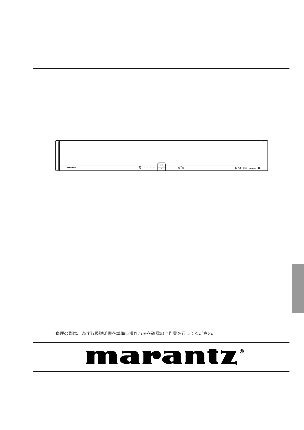
Home Theater System
Please use this service manual with referring to the user guide ( D.F.U. ) without fail.
ES7001
Part no. 90M20AJ855020
First Issue 2007.09
MZ
MARANTZ DESIGN AND SERVICE
USA
MA R ANT Z AM E RIC A , IN C
100 CORPORATE DRIVE
MAHWAH, NEW JERSEY 07430
USA
EUROPE / TRADING
MA R ANT Z EU R OPE B .V.
P. O. BOX 8744, BUILDING SILVERPOINT
BEEMDSTRAAT 11, 5653 MA EINDHOVEN
THE NETHERLANDS
PHONE : +31 - 40 - 2507844
FAX : +31 - 40 - 2507860
KOREA
D&M SALES AND MARKETING KOREA LTD.
CHUNG JIN B/D., #1001,
53-5, WONHYORO 3 GA, YONGSAN-GU,
SEOUL, 140-719, KOREA
PHONE : +82 - 2 - 323 - 2155
FAX : +82 - 2 - 323 - 2154
CANADA
D& M CAN A DA I NC.
5-505 APPLE CREEK BLVD.
MARKHAM, ONTARIO L3R 5B1
CANADA
JAPAN
D&M BUILDING, 2-1 NISSHIN-CHO,
KAWASAKI-KU, KAWASAKI-SHI,
KANAGAWA, 210-8569 JAPAN
D& M Hol d in g s In c .
CHINA
MARAN TZ SHAN GH AI TRAD ING LTD .
ROOM.506 SHANGHAI LIGHT INDUSTRY MANSION
1578 NANJING (WEST) ROAD SHANGHAI
CHINA
TEL : 021 - 6248 - 1064
FAX : 021 - 6248 - 3565
Using superior design and selected high grade components,
Only original
MARANTZ
parts can insure that your
MARANTZ
MARANTZ
product will continue to perform to the specifications for which
company has created the ultimate in stereo sound.
it is famous.
Parts for your
MARANTZ
ORDERING PARTS :
equipment are generally available to our National Marantz Subsidiary or Agent.
Parts can be ordered either by mail or by Fax.. In both cases, the correct part number has to be specified.
The following information must be supplied to eliminate delays in processing your order :
1. Complete address
2. Complete part numbers and quantities required
3. Description of parts
4. Model number for which part is required
5. Way of shipment
6. Signature : any order form or Fax. must be signed, otherwise such part order will be considered as null and void.
NOTE ON SAFETY :
Symbol Fire or electrical shock hazard. Only original parts should be used to replaced any part marked with symbol .
Any other component substitution (other than original type), may increase risk of fire or electrical shock hazard.
安全上の注意:
がついている部品は、安全上重要な部品です。必ず指定されている部品番号のものを使用して下さい。
SHOCK, FIRE HAZARD SERVICE TEST :
CAUTION : After servicing this appliance and prior to returning to customer, measure the resistance between either primary AC
cord connector pins ( with unit NOT connected to AC mains and its Power switch ON ), and the face or Front Panel of product
and controls and chassis bottom.
Any resistance measurement less than 1 Megohms should cause unit to be repaired or corrected before AC power is applied,
and verified before it is return to the user/customer.
Ref. UL Standard No. 60065.
In case of difficulties, do not hesitate to contact the Technical
Department at above mentioned address.
070719MZ
1. TECHNICAL SPECIFICATIONS
Audio power amplifier
Rated power output
(20 Hz-20 kHz / THD = 0.05%) ........................ 26 W/ch 6
Maximum power output (1 kHz/JEITA) ..................30 W/ch 6
Frequency characteristics
Analog input: ANALOG IN 1 .........20 Hz-20 kHz (± 3 dB)
Digital input: PCM 44.1 kHz .......... 20 Hz-20 kHz (± 3 dB)
S/N ratio: PCM 44.1 kHz ....................................... 100 dB
Decoding
Compatible playback signal formats
PCM audio (fs = 32 kHz, 44.1 kHz, 48 kHz)
DOLBY DIGITAL
DTS
AAC
Binaural
Power supply
Power requirements
[/F] ......................................................AC 100 V, 50/60 Hz
[/K] .....................................................AC 220 V, 50/60 Hz
[/N] ..........................................................AC 230 V, 50 Hz
[/U] ..........................................................AC 120 V, 60 Hz
Power consumption ........................................................40 W
.................125 W (6Ω, 30 W x 2 outputs)
Power consumption in standby mode ............................0.8 W
Input
OPT IN (optical digital) .............................................. 3 inputs
HDMI IN (Version 1.1) ............................................... 2 inputs
ANALOG IN .................................................. 2 inputs (stereo)
Output
HDMI OUT (Version 1.1) ...........................................1 output
SUB W. PREOUT ......................................................1 output
REMOTE OUT ........................................................... 1 output
Speakers
Tweeter .................................... 1.9 cm (3/4 inches) dome x 2
Midrange ....................................8 cm (3 1.4 inches) cone x 2
Woofer .....................................12 cm (4 3.4 inches) cone x 2
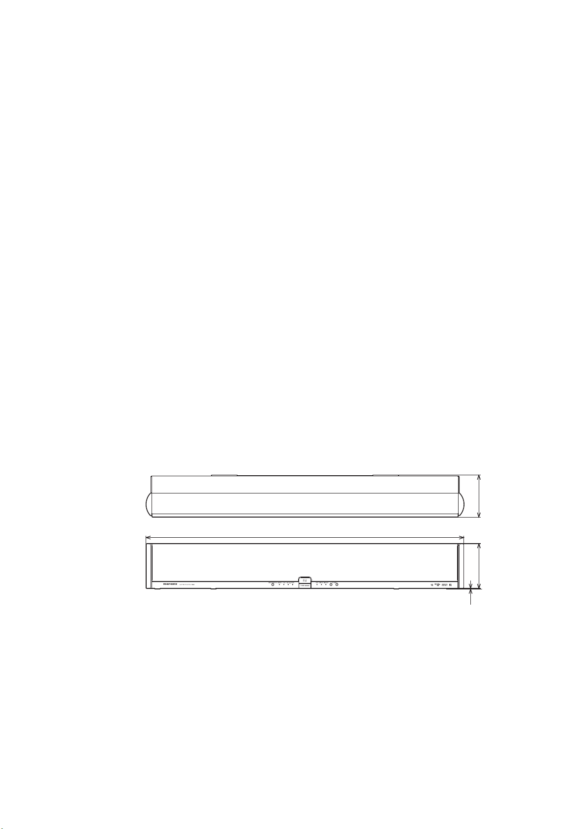
Dimensions (unit)
Width .............................................1,080 mm (42 5/8 inches)
Height ................................................. 153 mm (6 1/8 inches)
Depth .................................................. 144 mm (5 3.4 inches)
Mass (unit) .................................................. 12 kg (26 lb 7 oz)
Supplied accessories
Remote controller
RC001ES [/F] ..................................................................1
RC002ES [/K/N/U] ..........................................................1
AAA batteries .......................................................................2
Optical fiber cable [/F] ........................................................... 1
2. CAUTION
The layout of this amplifier is well concerned for sound
quality.
1. When screws and washers are removed, those parts
must be set to the same places.
2. When wires are removed, the wires must be installed in
the same roots, same places.
Note:
The speaker nets cannot be removed.
サランネットは取り外せません。
144
1080
153
2
2. 注意
当機は音質を考慮したレイアウトになっています。
1. ネジやワッシャ類を取り外した場合、元の位置に取り付け
てください。
2. ワイヤ類を取り外した場合の配線ルートは、元のルート通
りに戻してください。
1

3. FEATURES
¶ What is OPSODIS?
● OPSODIS とは
Tre bl e
Bass Bass
OPSODIS (Optimal Source Distribution) is a new virtual surround technology developed
by the Institute of Sound and Vibration Research (ISVR) and Kajima Corporation.
OPSODIS technology has been united with Marantz’s high-quality sound technology
to realize a superior surround environment than ever before.
The ES7001 realizes reproduction of omni-directional sound only with the speakers
built in this unit.
The ES7001 releases listeners from the conventional surround environment that has
required complex installation of five or more speakers. As a result, installing the AV
system in a room has little effect on their lifestyle or living environment.
The unit incorporates a 6-channel digital power amplifier, allowing direct drive of the
speakers’ tweeter, midrange and woofer.
The digital audio signals are input to the digital amplifier of the unit through the optical
digital and the HDMI connectors without digital-analog conversion.
[PWM PROCESSOR SECTION]
Using digital filters for cutoff frequency of the 6 channel digital power amplifier enables
extreme filter precision that cannot be achieved with conventional analog filters,
providing the OPSODIS effects more efficiently.
高音
低音 低音
OPSODIS(OPtimal SOurce DIStributiontechnology:オプソーディス)とは、英国
サウサンプトン大学 音響技術研究所(ISVR)、および鹿島建設株式会社が開発した立
体音響技術です。
この OPS OD IS テクノロジーとマランツの高音質開発技術が、これまでに無いサラウ
ンド環境の提案を目的に融合しました。
CINEMARIUM ES7001は本機搭載のスピーカーのみで全方向の音の再現が可能にな
ります。
今までの 5 本以上のスピーカー設 置が必要とされるサラウンド環 境からリスナーを開
放し、ライフスタイルやインテリアに対する AV システムの影響を大きく軽減すること
ができます。
【デジタルアンプ部】
6 チャンネルデジタルアンプを搭載し、スピーカーのツイーターレンジ 、ミッドレンジ、
ウーハーレンジをダイレクトに駆動しています。
HDMI 及び光デジタル接 続されたデジタル音声信 号はアナログ変 換することなく、
デジタルアンプに入力されます。
[POWER SUPPLY SECTION]
The R-core transformer is adopted for the power supply section of this unit. Thanks
to the features of the R-core transformer—less leakage magnetic flux, less heat
generation and quick response to overload variation—the unit produces a high quality
and powerful sound.
[CABINET]
Adoption of high-rigidity aluminum for the cabinet of the unit provides a sophisticated
stiff construction, allowing reproduction of beautiful crystalline sound.
[OTHER FEATURES]
¶ The OPT IN and HDMI IN connectors are compatible with Dolby Digital 5.1ch, DST
and AAC audio inputs.
¶ Supports Dolby PL II feature for 2-channel signal input and for digital signal input.
¶ Binaural recording* sources can be reproduced through the front speaker.
* Binaural recording is a method of recording audio which uses two microphones mounted in the ears of
a dummy head in the shape of the human head and ears.
Binaural recording can reproduce location of sound behind, ahead, above and below. It makes you feel
a real sense of distance.
Normally, a dramatic binaural effect can be achieved only with headphones.
However, a similar or more stereophonic effect can be achieved by playback of a binaural recording
source using this unit than that with headphones.
¶ The newest 32 bit DSP circuits adopted (one for decoding of Dolby, DST, ACC and
PCM, and two dedicated for OPSODIS circuits)
【PWMプロセッサー部】
6 チャンネルデジタルアンプのカットオフ周波数に於いて、デジタルフィルターを使用
することにより、従来のアナログフィルターでは成し得なかった精度の高いフィルター
が構成できるので、OPSODIS の効果をより効率良く引き出しています。
【電源部】
電源部は漏 洩磁束や発熱が少なく、過負荷変動に対して応答性が高い R コアトランス
を採用し、高音質で迫力のある音を実現しています。
【キャビネット】
本体キャビネットには高剛性のアルミニウムを採用することにより、精巧かつ強 靭な
キャビネット構造を実現しています。この結果、透明 度の高い高音質なサウンドを再
生しています。
【その他の特徴】
●OPT.入力およびHDMI 入力は DolbyDigital5.1ch、DTS およびAAC 入力に対応。
●2chソースはDolbyPL
●バイノーラル録音
※バイノーラル録音とは、人間の頭や耳の形をしたダミーヘッドの耳の部 分に2 本のマイクロホンをセットして録 音し
た方式をいいます。
その音源をヘッドホンで聞くと、音源の前 後左右上下 方向や距離感がリアルに再 現できますが、通常、 バイノーラル
録音されたソースはヘッドホンでしか大きな効果を得られません。
本機を使って音源を再生すると、ヘッドホン使用時と同等以上の立体音響効果を得ることができます。
●
32 ビット最新 D SPを 3 系統使用(1 系統は Dol by /D TS / AA C / P CM のデコードに使 用。
残りの2 系統はOPSODIS処理専用に使用。)
Ⅱに対応。(Digital 入力にも対応します)
※
のソースをフロントスピーカーで体験できるバイノーラルモード機能。
2

DOLBY
Manufactured under license from Dolby Laboratories. “Dolby”, “Pro Logic”, and the double-D
symbol are trademarks of Dolby Laboratories.
AAC
AAC is a format of the MPEG2 standard. This features excellent high-compression encoding and
high-quality sound, enabling reproduction of 2-channel stereo sound and 5.1-channel surround,
and bilingual broadcast. The following is the patent numbers of this format.
5848391 5,291,557 5,451,954 5 400 433 5,222,189
5,357,594 5 752 225 5,394,473 5,583,962 5,274,740
5,633,981 5 297 236 4,914,701 5,235,671 07/640,550
5,579,430 08/678,666 98/03037 97/02875 97/02874
98/03036 5,227,788 5,285,498 5,481,614 5,592,584
5,781,888 08/039,478 08/211,547 5,703,999 08/557,046
08/894,844 5,299,238 5,299,239 5,299,240 5,197,087
5,490,170 5,264,846 5,268,685 5,375,189 5,581,654
5,548,574 5,717,821 08/937,950 05-183,988 08/506,729
08/576,495 08/392,756
DTS
“DTS” and “DTS VIRTUAL” are registered trademarks of Digital Theater Systems, Inc.
BVcj[VXijgZYjcYZga^XZchZjcYZgJ#H#EViZciÉh/*!)*&!.)'0*!.*+!+,)0*!.,)!(-%0
*!.,-!,+'0+!)-,!*(*di]ZgJ#H#VcYldgaYl^YZeViZcih^hhjZYeZcY^c\#9IH^hV
gZ\^hiZgZYigVYZbVg`VcYi]Z9IHad\dh!HnbWdaVcY9IHK^gijVaVgZigVYZbVg`hd[9IH!
>cX#&..+"'%%,9IH!>cX#6aaG^\]ihGZhZgkZY#
● DOLBY
ドルビーラボラトリーズからのライセンスに基づき製造されています。
Dolby、ドルビー、ProLogic及びダブルD 記号及びAAC ロゴは、ドルビーラボラトリーズ
の商標です。
エーエーシー
● A
BS デジタル放送および地上波デジタル放送が採用している音声方式で、MPEG2 規格のひとつで
す。高圧縮率と高音質が特長で、2CH ステレオ音声に加え、5.1CHサラウンド音声や多言語放送
を可能にしています。以下はパテントナンバーです。
5848391 5,291,557 5,451,954 5400433 5,222,189
5,357,594 5752225 5,394,473 5,583,962 5,274,740
5,633,981 5297236 4,914,701 5,235,671 07/640,550
5,579,430 08/678,666 98/03037 97/02875 97/02874
98/03036 5,227,788 5,285,498 5,481,614 5,592,584
5,781,888 08/039,478 08/211,547 5,703,999 08/557,046
08/894,844 5,299,238 5,299,239 5,299,240 5,197,087
5,490,170 5,264,846 5,268,685 5,375,189 5,581,654
5,548,574 5,717,821 08/937,950 05-183,988 08/506,729
08/576,495 08/392,756
● DTS
DTSおよびDTSVIRTUAL は、DigitalTheaterSystem,Inc. の登録商標です。
● OPSODIS
OPSODISは、OPSODISLTD.の登録商標です。
AC
アドバンスド
(A
dvancedA
オーディオ
udioC
コーディング
oding)
OPSODIS
OPSODIS is a registered trademark of the OPSODIS LTD.
7 About the Protective Circuit
This unit incorporates a protective circuit that
protects the amplifier circuits and speaker
system against damage.
As soon as the protective circuit works, the unit
goes into standby mode and the STANDBY
indicator flashes at the same time.
For power-on
For 3 or 4 seconds after the power of the unit
is turned on the protective circuit works and
the sound is muted. Once the amplifier circuits
are stabilized, the protective circuit is released
and the sound is restored.
For heat-up of the power amplifier
When the power amplifier of the unit heats up
under the following conditions, the protective
circuit works and the unit goes into the standby
mode.
•
The unit is kept used with excessive signal
input, and the temperature of the main
amplifier section exceeds the set operating
temperature.
•
Since the ventilation holes at the rear of the
unit are blocked or the unit is installed in a
narrow rack, the internal temperature of the
unit exceeds the set operating temperature.
In this case, wait until the temperature is
sufficiently lowered, then turn on the unit and
operate it at a lower volume.
■ 保護回路について
本機にはアンプ回 路およびスピーカーユニッ
トを破損から保護する「保護回路」を搭載して
います。
保護回路が動作するとすぐに待機状態になり、
待機インジケーターが点滅します。
●電源投入時
電源投入後からアンプ回路が安定するまでの
約 3 〜 4 秒間、保護回 路が働き、ミューティ
ング状態になります。
その後、アンプ回路が安定すると保護回路を
解除し、音が出る状態になります。
●パワーアンプが加熱した時
下記の様にパワーアンプが加熱した時、保護
回路が働き、すぐに待機状態になります。
•過大な信号が入力された状態で連続使用
し、メインアンプ部の温度が設定以上の温
度になった時。
•後面の通風孔を塞いで使用したり、狭い
ラックに入れて使用し、設定以上の温度に
なった時。
この時、温 度が下がってから電源を入れ、ボ
リュームを少し絞ってください。
3
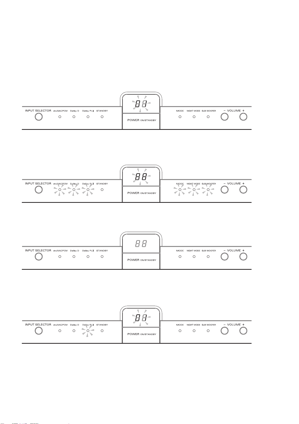
4. SERVICE MODE
Microprocessor (QU01), CS DSP (Q102) and TI DSP (Q202,
Q302) Version and LED Segment Check Mode.
1. While the power is on, press ON/STANDBY and VOLUME
(-) buttons simultaneously more than 3 seconds.
The software version of the microprocessor (QU01) is
displayed.
2. Push the MODE button of remote controller, all of the LED
segments and LED indicators lights. (Exclude STANDBY
LED)
Microprocessor (QU01)、CS DSP (Q102)および、TI DSP
、Q302)のVersion表示および、LED点灯を確認するモ
(Q202
ードです。
1. 本機の電源を入れます。電源と音量(−)ボタンを同時に3秒
以上押します。
マイコン
(QU01)のバージョンが表示されます。
2. リモコンのMODEボタンを押します。LEDが全点灯しま
す。
(待機LED は除く)
3. Push the MODE button of remote controller, all of the LED
segments and LED indicators turn off.
4. Push the MODE button of remote controller, the software
version of the CS DSP Flash (Q102) is displayed. And the
Dolby PLII indicator lights.
リモコンのMODEボタンを押します。LEDが全消灯しま
3.
す。
4. リモコンのMODEボタンを押します。CS DSP用Flash
のバージョンが表示されます。Dolby PLIIのLEDが
(Q102)
点灯します。
4
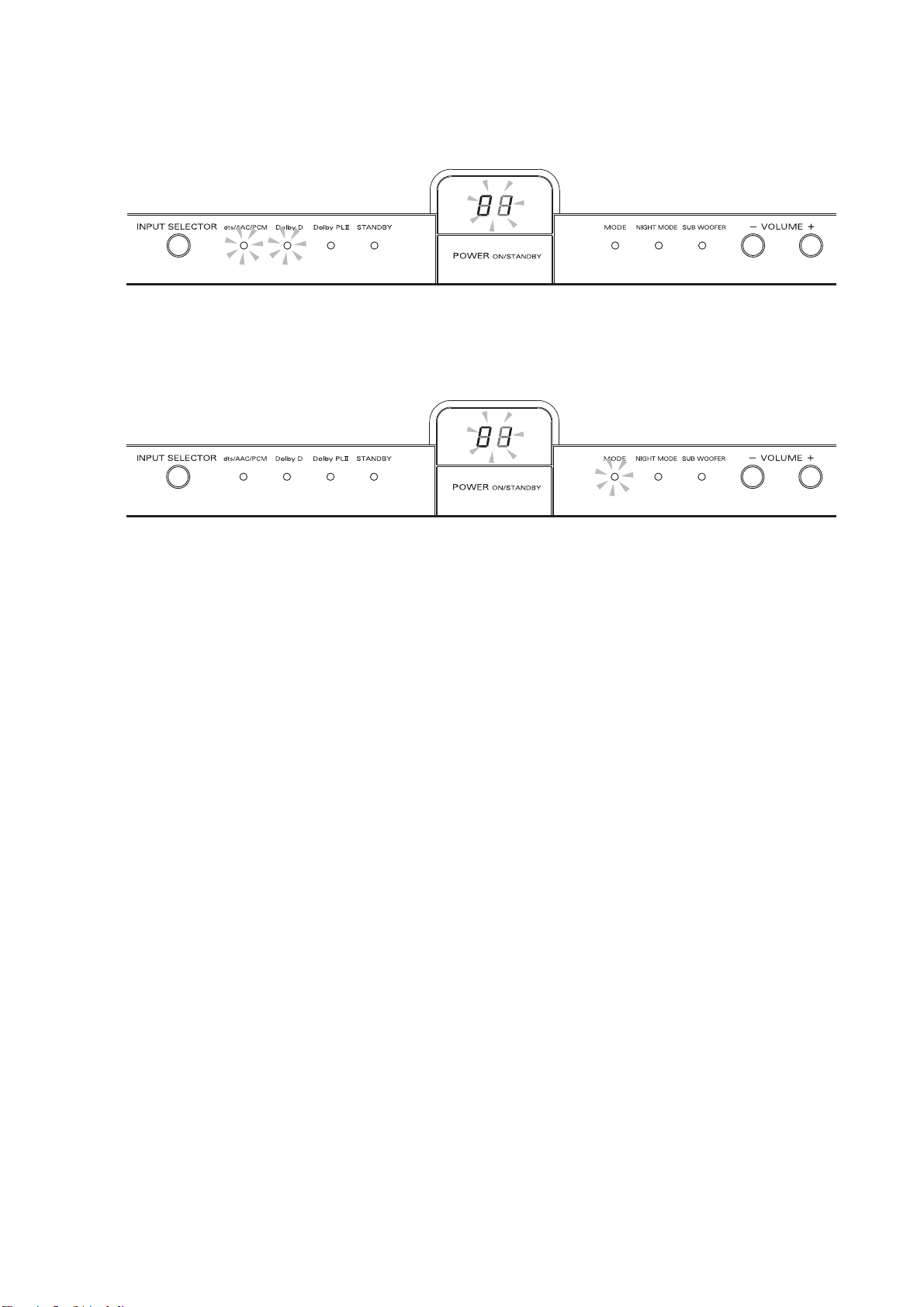
5. Push the MODE button of remote controller, the software
version of the TI DSP Flash (Q202) is displayed. And
the dts/AAC/PCM and Dolby D indicators lights.
5. リモコンのMODEボタンを押します。TI DSP用Flash
のバージョンが表示されます。dts/AAC/PCMと
(Q202)
Dolby DのLEDが点灯します。
6. Push the MODE button of remote controller, the
software version of the TI DSP Flash (Q302) is
displayed. And the MODE indicator lights.
7. Push the MODE button of remote controller, turn off the
service mode. And volume level is displayed.
Product Reset
To reset the back up memory of the unit into the default
status, follow the procedure below.
1. Turn on the unit and press ON/STANDBY and VOLUME
(+) buttons simultaneously more than 3 seconds.
2. After "dF"(dF) is displayed on the display about 2 seconds.
3. After 2 seconds, power is turned off automatically.
4. The unit is turned on immediately after, "on"(on), "CL"(CL)
and "00"(00) are displayed in order on the LED display,
and EEPROM is cleared to the default status.
7 Initial settings of unit
Power ...................................................... ON
Input selector .......................................... DVD
Display window ...........volume level indication
Volume level .............................................. 00
7
Initial settings of setting items
Speaker installation height .......................... L
(installed in a lower place than the connected TV)
Number of audience ....2P (2 or more persons)
Viewing/listening distance ............... – – (2 m)
Subwoofer .. On (subwoofer output activated)
Binaural mode ........................................... off
Dolby PL
Multi-channel broadcast ....b1 (main channel)
Night mode ................................................ off
Dimmer ..............................nor mal brightness
Muting ....................................................... off
II ..........................P1 (PL II MOVIE)
6. リモコンのMODEボタンを押します。TI DSP 用Flash
のバージョンが表示されます。MODEのLEDが点
(Q302)
灯します。
7. リモコンのMODEボタンを押します。サービスモードが解
除され、現在の音量を表示します。
初期状態にするには
1. 本機の電源を立ち上げます。電源と音量(+)ボタンを同時に
3秒以上押します。
2. 約2秒後にLEDディスプレイに"dF"(dF)が表示されます。
3. 約2秒後に自動的に電源が切れます。
4. 直後に自動的に電源が入り、"on"(on), "CL"(CL), "00"(00)
の順にLEDディスプレイに表示され、初期化が終了しま
す。
■ 本機の初期状態
電源................................................................... ON
入力切替.........................................................DVD
表示部....................................................音量表示
音量.................................................................... 00
■ 設定項目初期状態
スピーカー高さ...........L(テレビより下に設置)
視聴人数........................................ 2P(2 人以上)
視聴距離............................................... −−(2m)
サブウーハー........ On(サブウーハー出力オン)
バイノーラルモード............................. オフ状態
DolbyPL
音声多重............................................b1(主音声)
ナイトモード......................................... オフ状態
ディマー............................................................. 明
消音......................................................... オフ状態
Ⅱ..........................P1(PL ⅡMOVIE)
5
5. SYSTEM ERROR
When the microprocessor detects a trouble, the following
information is displayed on the Seven-segment display.
• The contents of the ERROR indication are the followings.
1. Trouble in DSP Code.
A mismatch between the group code of Main
microprocessor and DSP. (Indication is as it is, sound
muted and operation prohibition state.)
2. Trouble in EEPROM.
The data from EEPROM does not match.
Processing: Initialize EEPROM.
製品内部での異常発生時に処理、表示を行います。
• ERROR表示の内容は下記です。
1. DSP Code異常時。
メインマイコンとDSPのグループコードが不一致。
プログラムデータが破損した可能性があり。
(表示状態は保持、音声はMute、操作禁止状態)
2. EEPROM異常検出時。
EEPROM のデーターが不整合。
メインマイコンがロムのデータを正しく書き換えますの
で、設定した内容は全てクリアーされて工場出荷時の設定
にもどります。
(処理:EEPROMを初期化)
3. Trouble in EEPROM interface.
The Communication trouble between Main microprocessor
and EEPROM was found. The possibility of EEPROM
breakage.
4. Trouble in Amplifier power supply.
Turn on the unit, trouble in Amplifier power supply.
(Refer to page 3. )
5. Trouble in Amplifier.
Short-circuit of speaker cable and amplifier is high
temperature state. (Refer to page 3. )
3. EEPROM
インターフェースの異常検出時。
メインマイコンとEEPROMの通信が出来ない。
EEPROM破損の可能性あり。
4. Power ONのアンプ電源異常時。
電源オン時の電源異常表示。処理:スタンバイにする。
(3ページを参照)
5.
アンプ異常時。
スピーカーケーブルのショートやアンプが高温状態。
(3ページを参照)
6

6. WRITING AND UPDATE SOFTWARE
CPU (QU01) needs writing software, when a CPU (QU01)
is replaced.
Software for CPU and DSP (CS and TI) can be updated.
Have update application software. ("UpgradeDSP.exe",
"da610_writer.exe" and "H8Download.exe”)
There are three mode of download, regarding to the target
of software as bellow.
CPU (QU01)を交換する際は、CPU (QU01)へのソフトウェア
の書き込みが必要になります。
CPUおよびDSP(CSとTI)のソフトウェアのアップデートを行
います。
ソフトウェアのアップデートには
writer.exe
アップデートには次の
、およびH8Download.exeが必要です。
3つのモードがあります。
UpgradeDSP.exeとda610_
Mode 1: Update CS-DSP's software to 4M Flash-ROM.
This mode is to update the software for CS-DSP.
The target devise is 4M Flash-ROM (Q102) on PD01
(DSP PWB).
Unit needs connection to connection JIG with pushed
switch.
Unit needs to be set update condition, by two front keys.
The updating of software (DSP1) takes about 2 minutes.
Mode 2: Update TI-DSP's software to 4M Flash-ROM.
This mode is to update the software for TI-DSP.
The target devise is 4M Flash-ROM (Q202 and Q302) on
PD01 (DSP PWB).
Unit needs connection to connection JIG with pushed
switch.
Unit needs to be set update condition, by two front keys.
The updating of software (DSP2) takes about 2 minutes.
The updating of software (DSP3) takes about 9 minutes.
Mode 3: Update CPU's software to internal Flash-ROM.
This mode is to update the software for CPU.
The target devise is internal flash ROM of CPU (QU01)
on PD01 (DSP PWB).
Unit needs to be set to writing condition, by no pushing
switch of connection JIG.
The updating of software takes about 1 minute.
The following items are required for updating.
(NECESSARY EQUIPMENT)
• Windows PC (OS: Windows2000 or WindowsXP) with
Serial port.
• RS-232C Dsub-9 pin cable (female to female/straight
type)
• Update software to CPU. (H8Download.exe, etc... in CPU
folder)
• Update software to CS_DSP. (UpgradeDSP.exe, etc... in
CS_DSP folder)
• Update software to TI_DSP. (da610_writer.exe, etc... in
TI_DSP folder)
• Connection JIG (90M-ES150AJIG)
Use RS232C Dsub-9 pin cable (female to female/straight
type) to connect PC and the connection JIG.
Serial port on PC needs to be set by dialog box for each
program. Serial port can be set from COM1 to COM5.
Mode 1:CS-DSP用Flash-ROMのアップデート
このモードはCS-DSPのソフトウェアをアップデートする
モードです。
PD01(DSP PWB)の基板上にあるFlash-ROM (Q102)のソ
フトウェアをアップデートします。
接続冶具内のスイッチをオンにして接続します。
本機のフロントパネルにある2つのボタンを押してアップデ
ートモードにします。
このDSP1用Flash ROMの書き換え時にかかる時間はおよ
そ
2分です。
Mode 2:TI-DSP用Flash-ROMのアップデート
このモードはTI-DSPのソフトウェアをアップデートするモ
ードです。
PD01(DSP PWB)の基板上にあるFlash-ROM (Q202と
Q302)のソフトウェアをアップデートします。
接続冶具内のスイッチをオンにして接続します。
本機のフロントパネルにある2つのボタンを押してアップデ
ートモードにします。
このDSP2用Flash ROMの書き換え時にかかる時間はおよ
そ
2分です。
このDSP3用Flash ROMの書き換え時にかかる時間はおよ
そ
9分です。
Mode 3:CPUの内部Flash-ROMのアップデート
このモードはCPUのソフトウェアをアップデートするモー
ドです。
PD01(DSP PWB)の基板上にあるCPU(QU01)の内部Flash-
のソフトウェアをアップデートします。
ROM
接続冶具内のスイッチをオフにしてアップデートモードに
します。
このCPUの内部Flash-ROMの書き換え時にかかる時間はお
よそ
1分です。
アップデートには下記の機器が必要です。
(必要機器)
• RS-232Cストレートケーブル(9Pinメス-9Pinメス)
• Windows PC Serial Port付き(OS: Windows2000,
WindowsXP)
• CPU用アップデートソフトウェア(CPUフォルダ内
H8Download.exe、他)
• CS-DSP用アップデートソフトウェア(CS_DSPフォルダ内
UpgradeDSP.exe、他)
• TI-DSP用アップデートソフトウェア(TI_DSPフォルダ内
da610_writer.exe、他)
• 接続冶具(90M-ES150AJIG)
RS-232C
を設定してください。
ケーブルで接続冶具と接続するPCのCOMポート番号
COMポート番号はCOM1からCOM5まで設定できます。
7
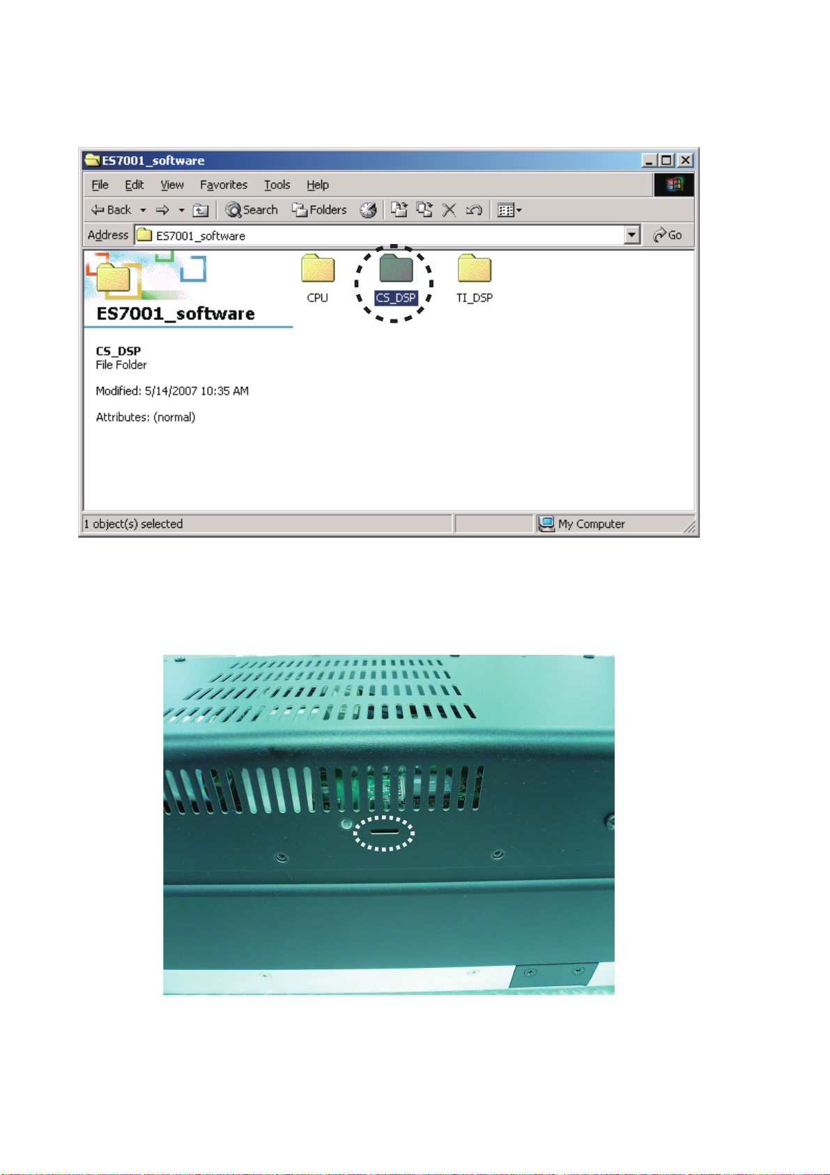
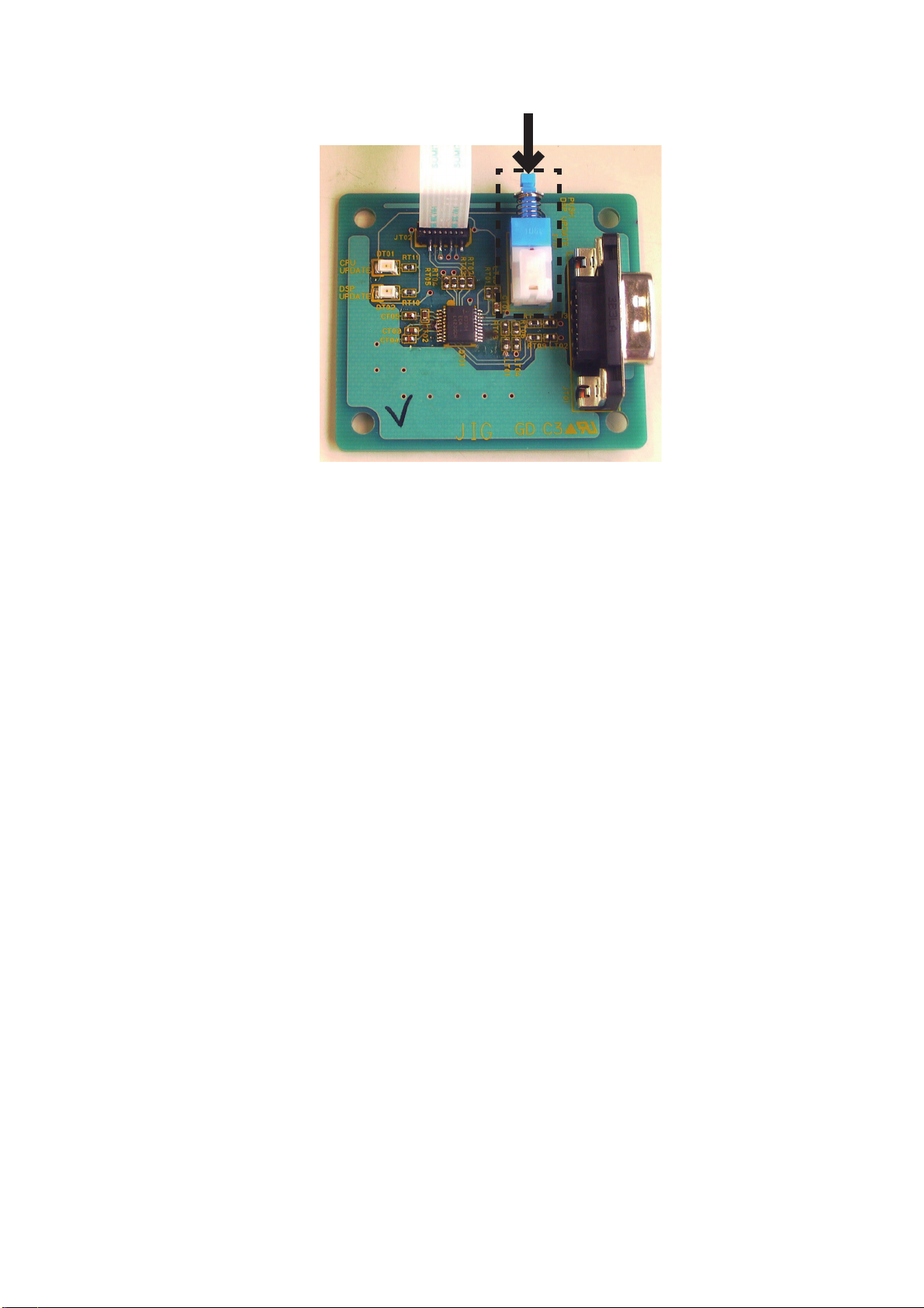
Download Firmware for CS-DSP (Mode 1)
1. Put the "CS_DSP" folder into anywhere on your PC's
hard disc.
CS-DSPのアップデート方法(Mode 1)
1. "CS_DSP"
す。
フォルダをPCのハードディスクにコピーしま
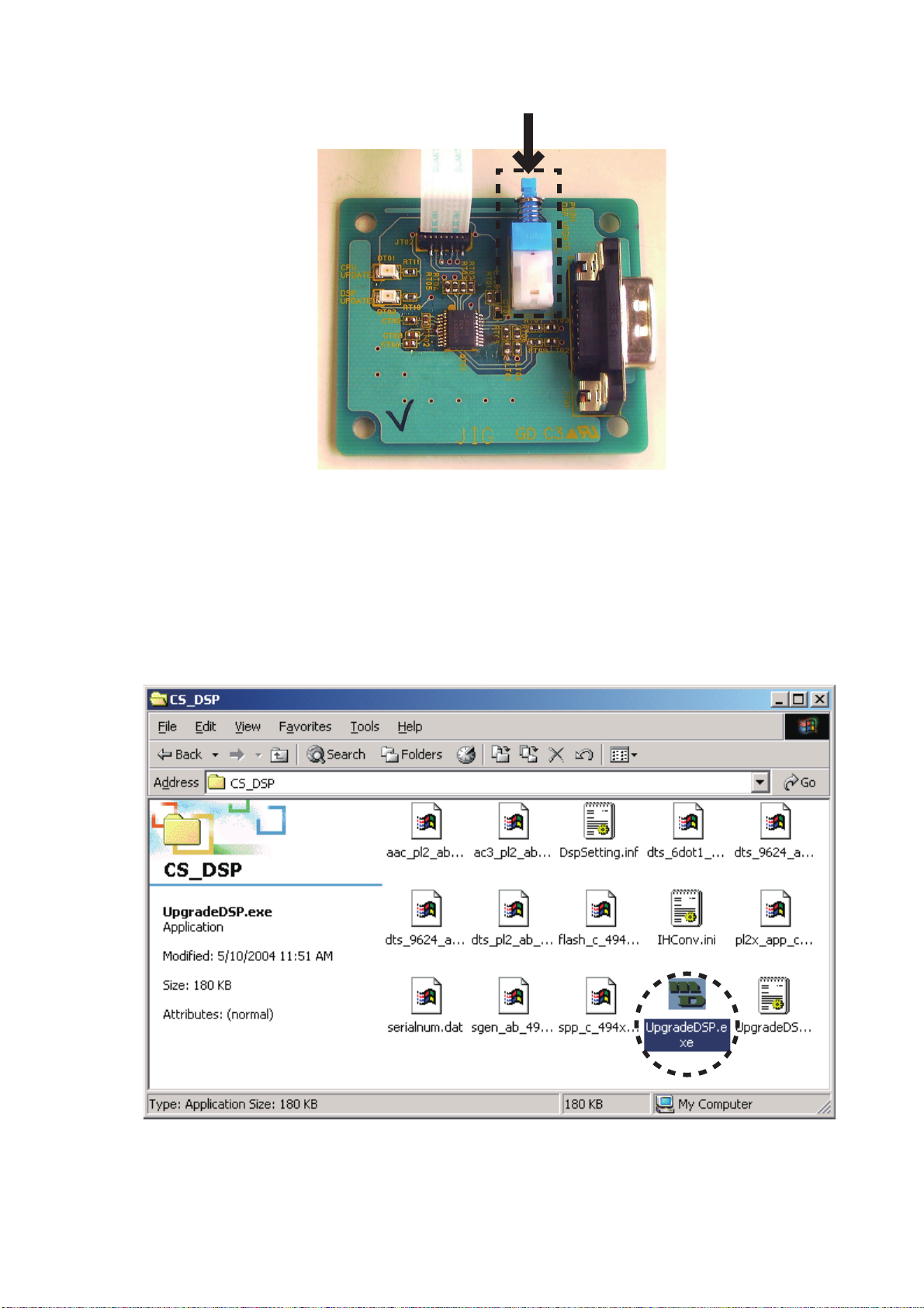
2. Connect PC and the connection JIG with the RS-
232C cable. And connect FPC (upside contact) to
the connector (JU05) into the rear lid of the unit from
connection JIG.
2. 本機と接続冶具をRS-232Cで接続し、接続冶具のFPCを
接続端子を上にして本機のリアカバー内のコネクタ
(JU05)に接続します。
8
3. Push the switch (ST01) of the connection JIG inside to
turn on the switch.
3. 接続冶具のスイッチ(ST01)を押し込みます。
4. Connect the mains cord into the unit and turn on the
unit. And then red LED (DT02) of connection JIG lights
up.
5. Double click the UpgradeDSP.exe. And Launch the
"marantz UpgradeDSP".
4. 電源ケーブルを本機に接続し、本機の電源を入れます。接
続冶具にある
LED(DT02)が赤く点灯します。
5. PCからUpgradeDSP.exeをダブルクリックして"marantz
UpgradeDSP"
を起動させます。
9
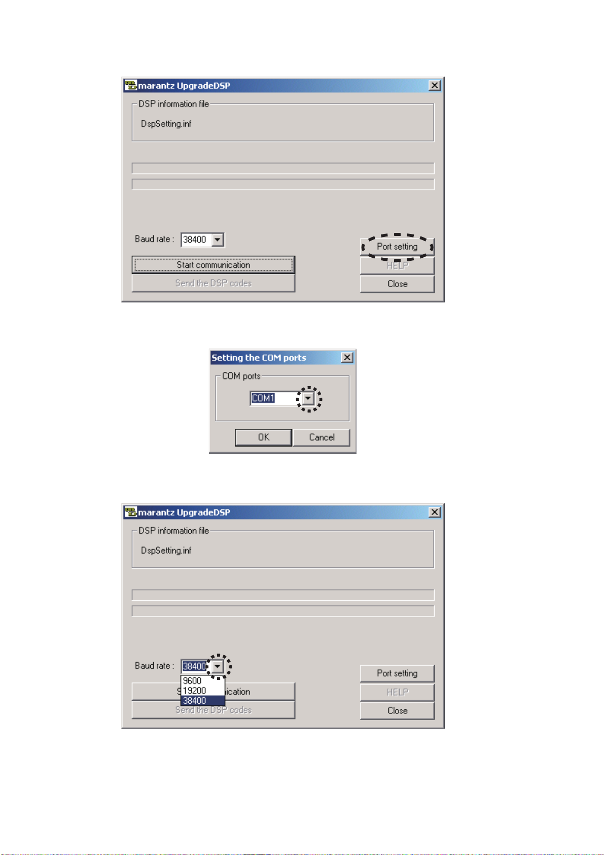
6. Click Port setting.
6. Port settingをクリックします。
7. Choose the COM Port No.
8. Choose 38400 in the Baud rate.
7. COMポート番号を選択します。
8. Baud rateを38400に設定します。
10
9. Press INPUT SELECTOR and VOLUME (-) buttons
simultaneously more than 5 seconds to turn the unit into
Loading Mode.
9. 入力切替、音量(−)の2つのボタンを同時に5秒以上押し続
けて
Loading Modeにします。
10. "Ld"(
11. Press INPUT SELECTOR button. And then "S1"(
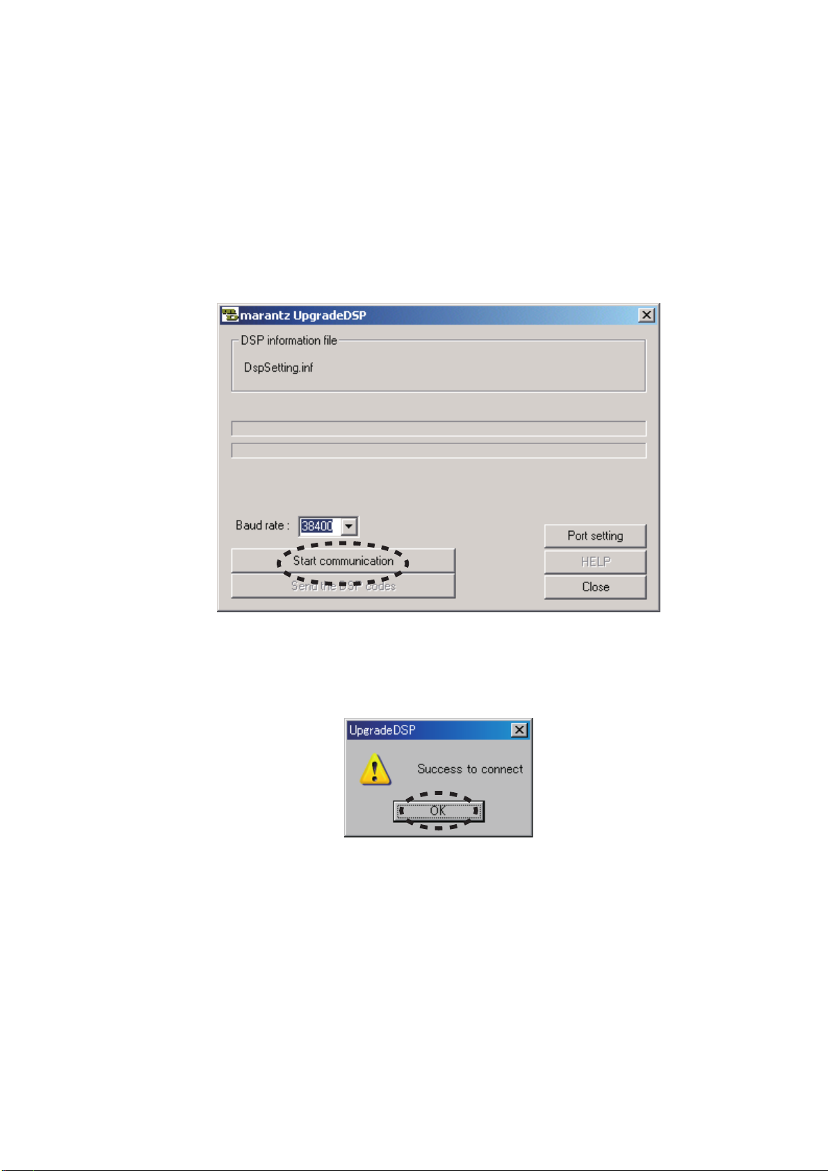
12. Click Start communication.
Ld) is shown on LED display. And the LED displays
"d1"(d1) after several seconds.
shown on LED display.
S1) is
10. LEDディスプレイに接続"Ld"(Ld)と表示され、さらに数秒
後に
"d1"(d1)と表示されます。
11. 本機のフロントパネルにある入力切替ボタンを押し"S1"
S1)と表示させます。
(
12. Start communicationをクリックします。
13. If the connection is made successfully, a dialog box
saying "Success to connect" appears and "cn"(
displayed on LED display. Click OK.
cn) is
13. 通信接続に成功すると下記のダイアログボックスが表示
され、
LEDディスプレイには"cn"(cn)が表示されます。
OKをクリックします。
11
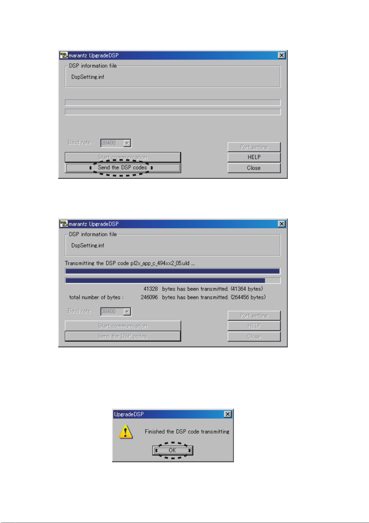
14. Click Send the DSP codes.
14. Send the DSP codesをクリックします。
15. Progress status of updating will be shown on PC and
Lo) is displayed on LED display.
"Lo"(
16. If updating is completed successfully, "En"(
En) is
displayed on LED display. And a dialog box saying
"Finished the DSP code transmitting" appears. Click OK
and then Application is closed automatically.
15. アップデートのステータスバーが表示され、LEDディスプ
レイには
16. アップデートが成功するとLEDディスプレイに"En"(En)と
表示されます。同時に
transmitting"
OKをクリックすると自動的にアプリケーションが閉じま
す。
"Lo"(Lo)が表示されます。
"Finished the DSP code
のダイアログボックスが表示されます。
12

17. Press ON/STANDBY button. The unit is turned off, and
then it is turned on automatically. The unit is reset at that
time. "on"(
on), "CL"(LC) and "00"(00) are displayed in
order on LED display.
NOTE : Press ON/STANDBY button, when "Er"(
Er) (ERROR)
is shown on LED display.
17. 本機の電源ボタンを押します。本機の電源が切れた後、自
動的に電源が入り、リセットされます。このとき
スプレイには
ます。
注意
: LEDディスプレイに"Er"(Er) (ERROR)が表示されたと
きも電源ボタンを押してください。
"on"(on), "CL"(CL), "00"(00)の順に表示され
LEDディ
18. Disconnect the mains cord from the unit. And
disconnect FPC of the connection JIG from the unit.
18. 本機から電源ケーブルを外します。その後、接続冶具の
FPCを外します。
13
Download Firmware for TI-DSP (Mode 2)
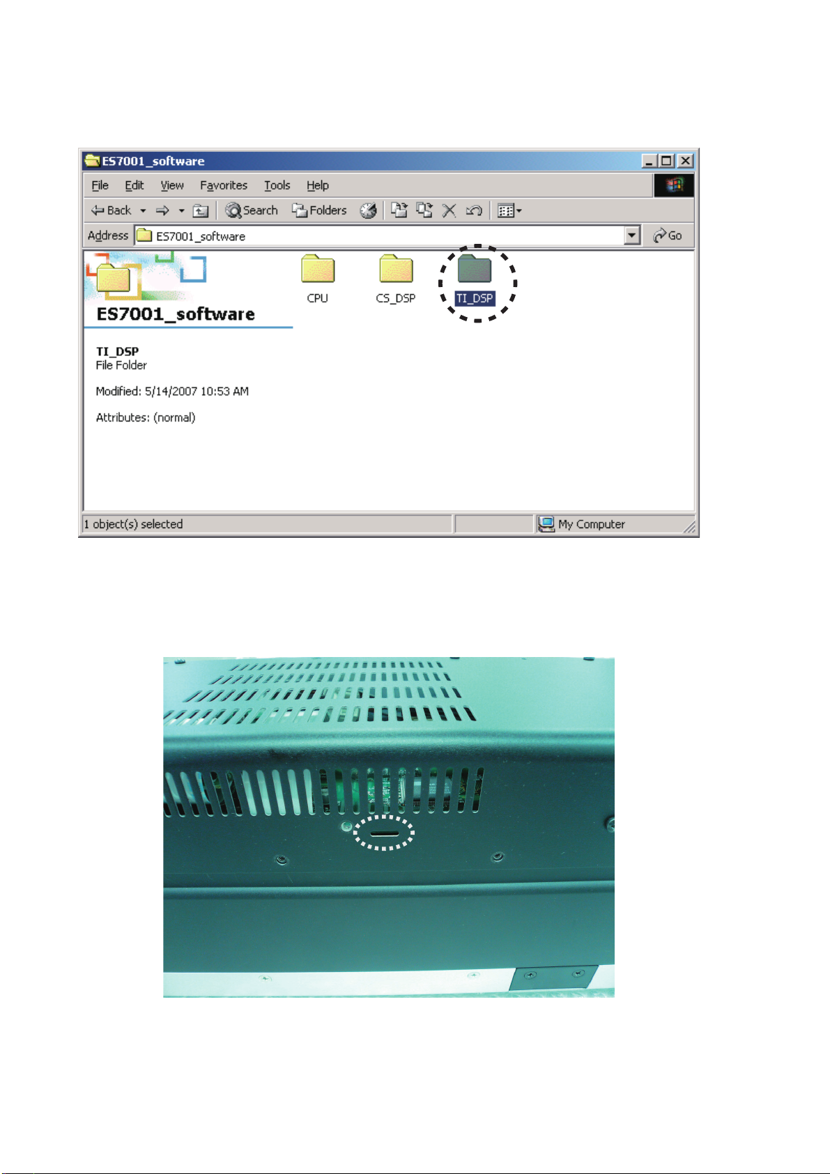
1. Put the "TI_DSP" folder into anywhere on your PC's
hard disc.
TI-DSPのアップデート方法(Mode 2)
1. "TI_DSP"
す。
フォルダをPCのハードディスクにコピーしま
2. Connect PC and the connection JIG with the RS-
232C cable. And connect FPC (upside contact) to
the connector (JU05) into the rear lid of the unit from
connection JIG.
2. 本機と接続冶具をRS-232Cで接続し、接続冶具のFPCを
接続端子を上にして本機のリアカバー内のコネクタ
(JU05)に接続します。
14
3. Puh the switch (ST01) of the connection JIG inside to
turn on the switch.
3. 接続冶具のスイッチ(ST01)を押し込みます。
4. Connect the mains cord into the unit and turn on the
unit. And then red LED (DT02) of connection JIG lights
up.
5. Press INPUT SELECTOR and VOLUME (-) buttons
simultaneously more than 5 seconds to turn the unit into
Loading Mode.
6. "Ld"(
Ld) is shown on LED display. And the LED displays
"d1"(d1) after several seconds.
7. Press VOLUME (-) button until "d2"(d2) is displayed on
LED display.
8. Press INPUT SELECTOR button. And then "S2"(
S2) is
shown on LED display.
電源ケーブルを本機に接続し、本機の電源を入れます。接
4.
続冶具にある
LED(DT02)が赤く点灯します。
5. 入力切替、音量(−)の2つのボタンを同時に5秒以上押し続
けて
Loading Modeにします。
6. LEDディスプレイに"Ld"(Ld)と表示され、さらに数秒後に
"d1"(d1)と表示されます。
7. 音量(−)ボタンを押し、LEDディスプレイに"d2"(d2)と表
示させます。
8. 入力切替ボタンを押し、LEDディスプレイに"S2"(S2)と表
示させます。
15
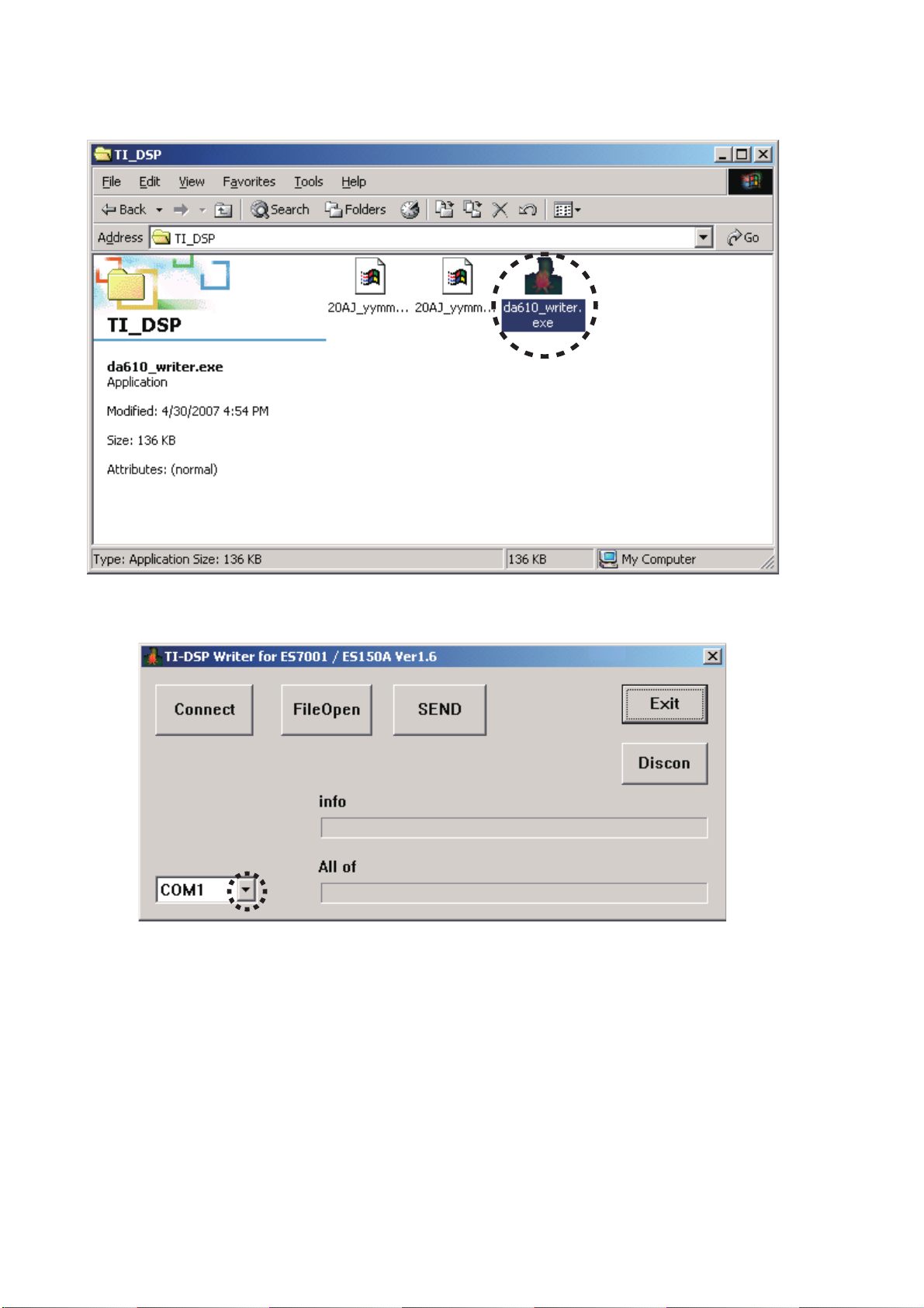
9. Double click the da610_writer.exe. And Launch the "TI-
DSP Writer for ES7001 / ES150A ver1.6".
9. PCからda610_writer.exeをダブルクリックして"TI-DSP
Writer for ES7001 / ES150A Ver1.6"
を起動させます。
10. Choose the COM Port No.
10. COMポート番号を選択します。
16
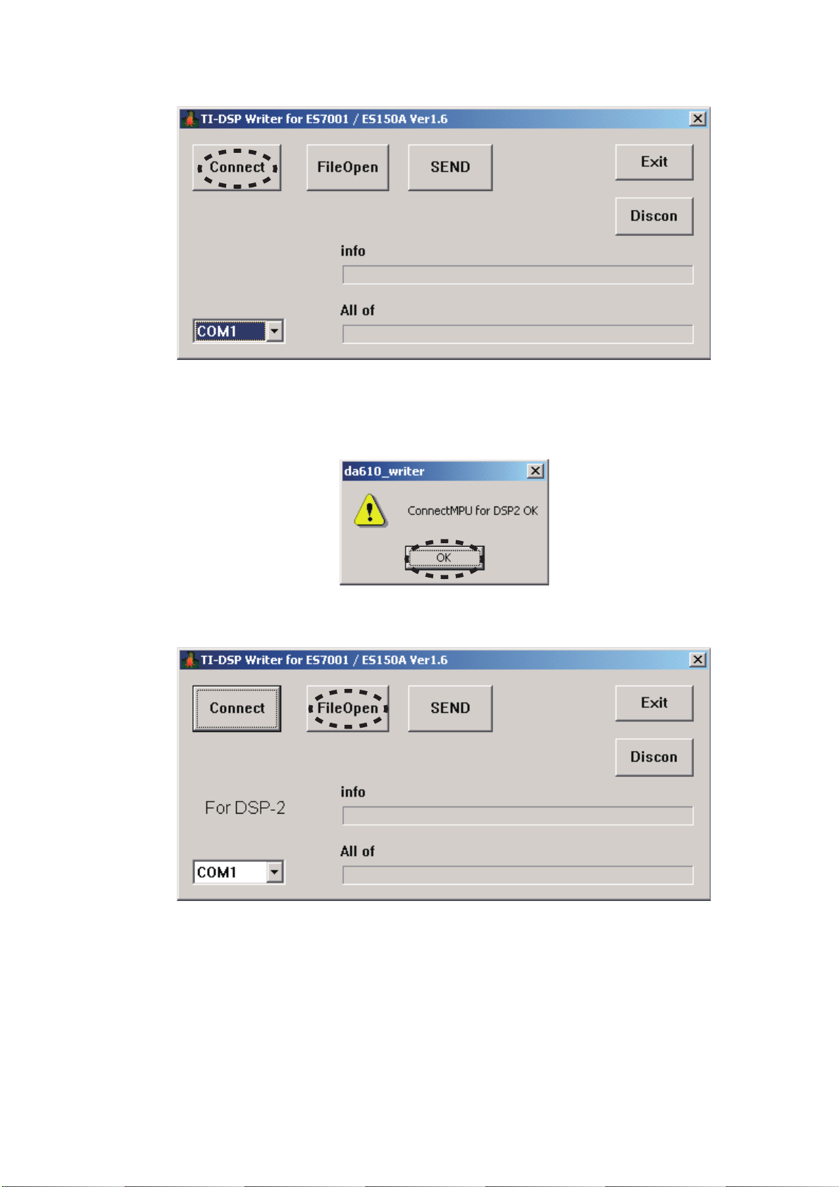
11. Click Connect.
11. Connectをクリックします。
12. If the connection is made successfully, a dialog box
saying "ConnectMPU for DSP2 OK" appears and "cn"
(
cn) is displayed on LED display. Click OK.
13. Click FileOpen.
12. 通信接続に成功すると"ConnectMPU for DSP2 OK"のダ
イアログボックスが表示され、
"cn"(cn)が表示されます。OKをクリックします。
13. FileOpenをクリックします。
LEDディスプレイには
17
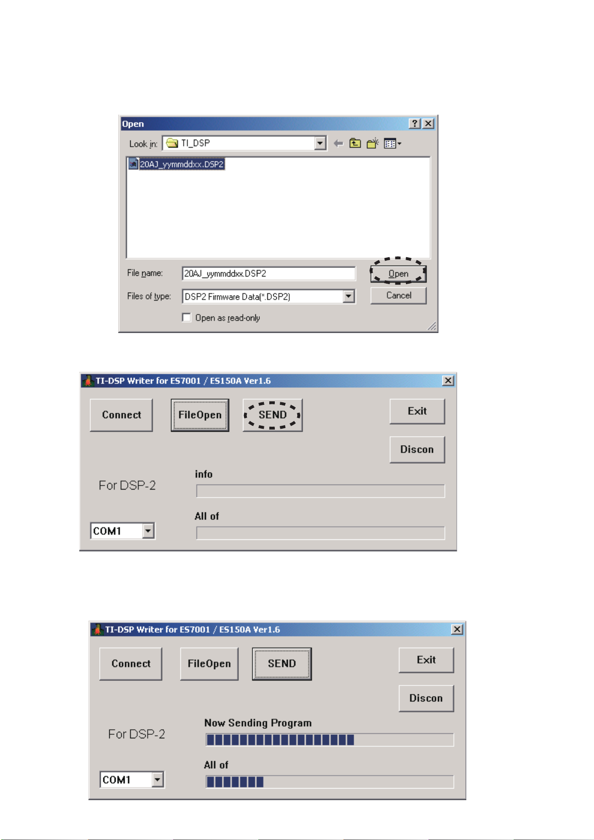
14. Choose 20AJ_yymmddxx.DSP2. And click Open.
NOTE : yy is two digits of year. mm is month. dd is
date. xx is version.
14. 20AJ_yymmddxx.DSP2を選択し、Openをクリックし
ます。
注意 : yyは年の下2桁、mmは月、ddは日、xxはバージョ
ンを表します。
15. Click SEND.
16. Progress status of updating will be shown on PC and
"Lo"(
Lo) is displayed on LED display.
15. SENDをクリックします。
16. アップデートのステータスバーが表示され、LEDディスプ
レイには
"Lo"(Lo)が表示されます。
18
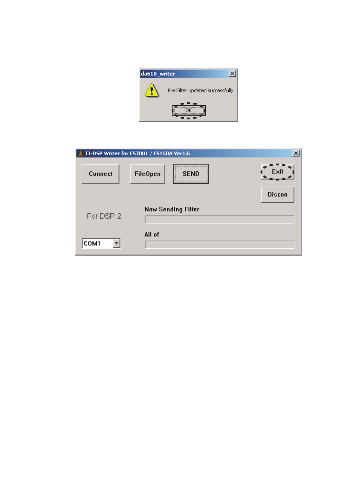
17. If updating is completed successfully, "En"(
En) is
displayed on LED display. And a dialog box saying "Pre
Filter updated successfully" appears. And click OK.
17. アップデートが成功するとLED ディスプレイに"En"(En)と
表示されます。同時に
ダイアログボックスが表示されます。
す。
"Pre Filter updated successfully"の
OKをクリックしま
18. Click Exit.
19. Press ON/STANDBY button. The unit is turned off, and
then it is turned on automatically. The unit is reset at that
time. "on(
on), "CL"(LC) and "00"(00) are displayed in
order on LED display.
18. Exitをクリックします。
19. 本機の電源ボタンを押します。本機の電源が切れた後、自
動的に電源が入り、リセットされます。このとき
スプレイには
ます。
"on"(on), "CL"(CL), "00"(00)の順に表示され
LEDディ
NOTE : Press ON/STANDBY button, when "Er"(
Er) (ERROR)
is shown on LED display.
20. Press INPUT SELECTOR and VOLUME (-) buttons
simultaneously more than 5 seconds to turn the unit into
Loading Mode.
21. "Ld"(Ld) is shown on LED display. And the LED displays
"d1"(d1) after several seconds.
22. Press VOLUME (-) button until "d3"(d3) is displayed on
LED display.
23. Press INPUT SELECTOR button. And then "S3"(S3) is
shown on LED display.
注意
: LEDディスプレイに"Er"(Er)(ERROR)が表示された
ときも電源ボタンを押してください。
20. 入力切替、音量(−)の2つのボタンを同時に5秒以上押し続
けて
Loading Modeにします。
21. LEDディスプレイに"Ld"(Ld)と表示され、さらに数秒後に
"d1"(d1)と表示されます。
22. 音量(−)ボタンを押し、FLディスプレイに"d3"(d3)と表示
させます。
23. 入力切替ボタンを押し、LEDディスプレイに"S3"(S3)と表
示させます。
19

24. Double click the da610_writer.exe. And Launch the "TI-
DSP Writer for ES7001 / ES150A Ver1.6".
24. PCからda610_writer.exeをダブルクリックして"TI-DSP
Writer for ES7001 / ES150A Ver1.6"
を起動させます。
25. Choose the COM Port No.
25. COMポート番号を選択します。
20
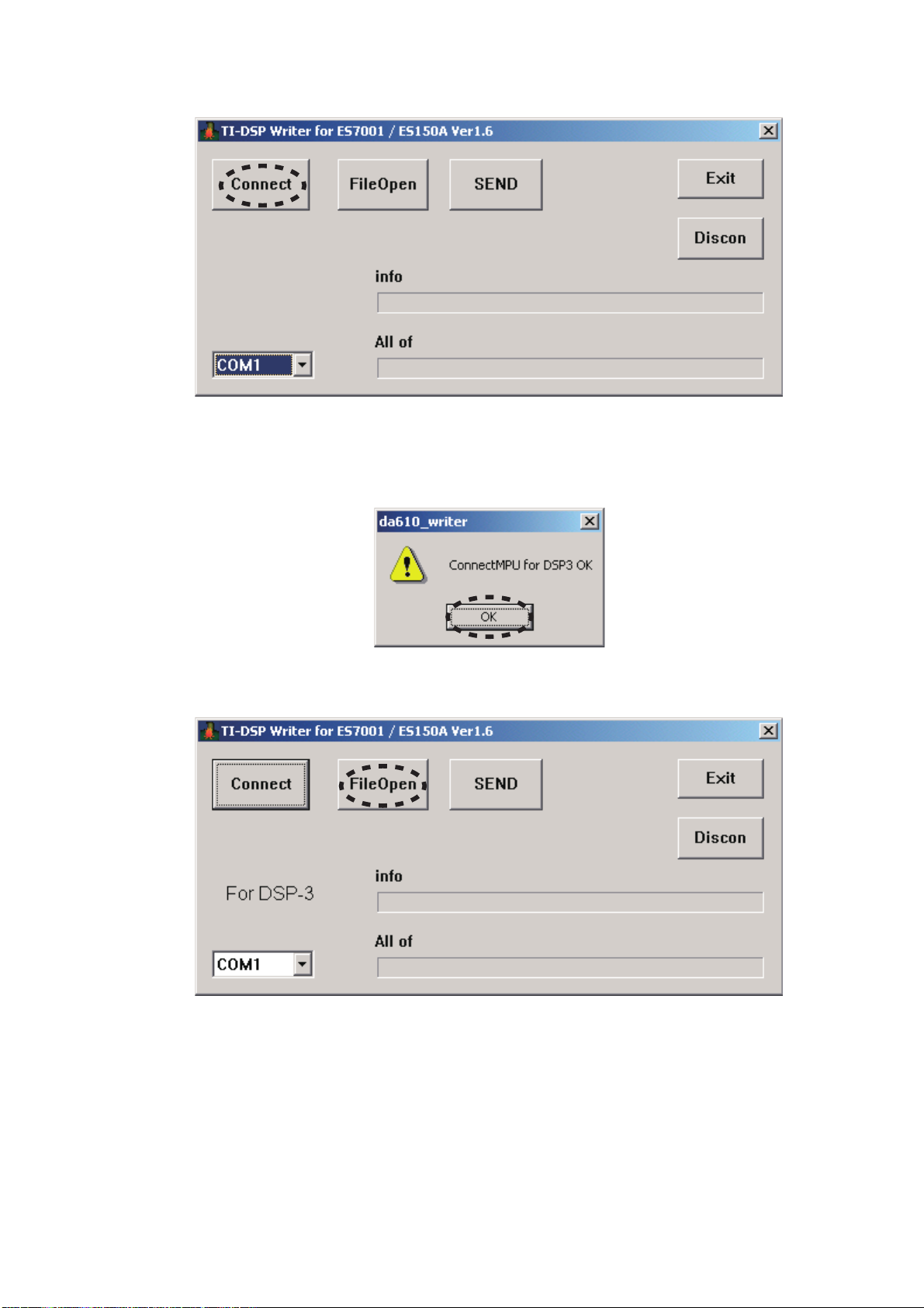
26. Click Connect.
26. Connectをクリックします。
27. If the connection is made successfully, a dialog box saying
"ConnectMPU for DSP3 OK" appears and "cn"(
cn) is
displayed on LED display. Click OK.
28. Click File Open.
27. 通信接続に成功すると"ConnectMPU for DSP3 OK"の
ダイアログボックスが表示され、
は
"cn"(cn)が表示されます。OKをクリックします。
28. FileOpenをクリックします。
LEDディスプレイに
21

29. Choose 20AJ_yymmddxx.DSP3. And click Open.
NOTE : yy is two digits of year. mm is month. dd is
date. xx is version.
29. 20AJ_yymmddxx.DSP3を選択し、Openをクリックし
ます。
注意 : yyは年の下2桁、mmは月、ddは日、xxはバージョ
ンを表します。
30. Click
SEND.
31. Progress status of updating will be shown on PC and
"Lo"(
Lo) is displayed on LED display.
30. SENDをクリックします。
31. アップデートのステータスバーが表示され、LEDディスプ
レイには
"Lo"(Lo)が表示されます。
22

32. If updating is completed successfully, "En"(En) is
displayed on LED display. And a dialog box saying "Pre
Filter updated successfully" appears. And click OK.
32. アップデートが成功するとLED ディスプレイに"En"(En)と
表示されます。同時に
ダイアログボックスが表示されます。
す。
"Pre Filter updated successfully"の
OKをクリックしま
33. Click Exit.
34. Press ON/STANDBY button. The unit is turned off, and
then it is turned on automatically. The unit is reset at that
time. "on"(
on), "CL"(LC) and "00"(00) are displayed in
order on LED display.
NOTE : Press ON/STANDBY button, when "Er"(Er) (ERROR)
is shown on LED display.
33. Exitをクリックします。
34. 本機の電源ボタンを押します。本機の電源が切れた後、自
動的に電源が入り、リセットされます。このとき
スプレイには
ます。
注意
: LEDディスプレイに"Er"(Er) (ERROR)が表示されたと
きも電源ボタンを押してください。
"on"(on), "CL"(CL), "00"(00)の順に表示され
LEDディ
35. Disconnect the mains cord from the unit. And
disconnect FPC of the connection JIG from the unit.
35. 本機から電源ケーブルを外します。その後、接続冶具の
FPCを外します。
23
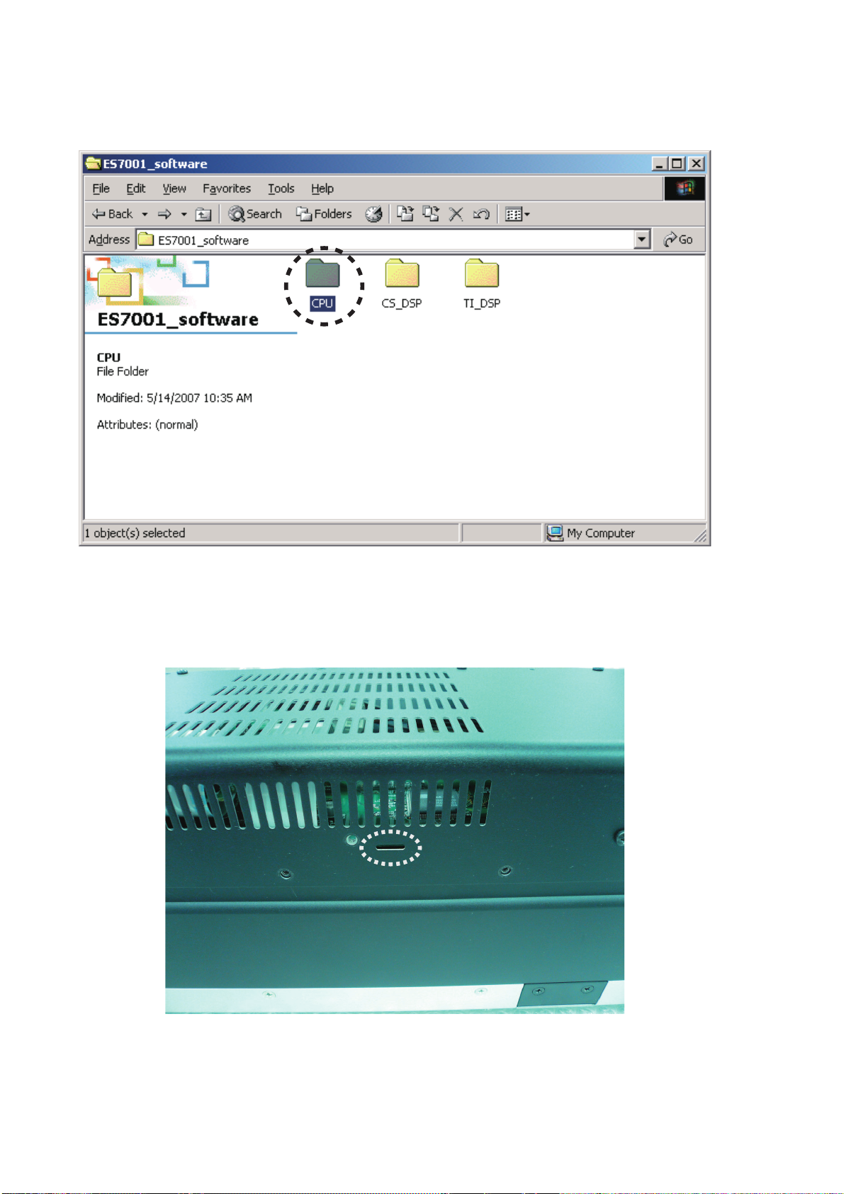
Download Firmware for CPU (Mode 3)
1. Put the "CPU" folder into anywhere on your PC's hard
disc.
CPUのアップデート方法(Mode 3)
1. "CPU"
フォルダをPCのハードディスクにコピーします。
2. Connect PC and the connection JIG with the RS-
232C cable. And connect FPC (upside contact) to
the connector (JU05) into the rear lid of the unit from
connection JIG.
2. 本機と接続冶具をRS-232Cで接続し、接続冶具のFPCを
接続端子を上にして本機のリアカバー内のコネクタ
に接続します。
(JU05)
24
3. Check the switch (ST01) of the connection JIG, it is not
pushed. It becomes boot mode.
3. 接続冶具のスイッチ(ST01)が押し込まれていないか確認し
ます。押し込まれていなければブートモードになります。
4. Connect the mains cord into the unit. And then green
LED (DT01) of connection JIG lights up.
NOTE : No indication of LED display and No light up
LED of the unit, when the unit is into boot mode.
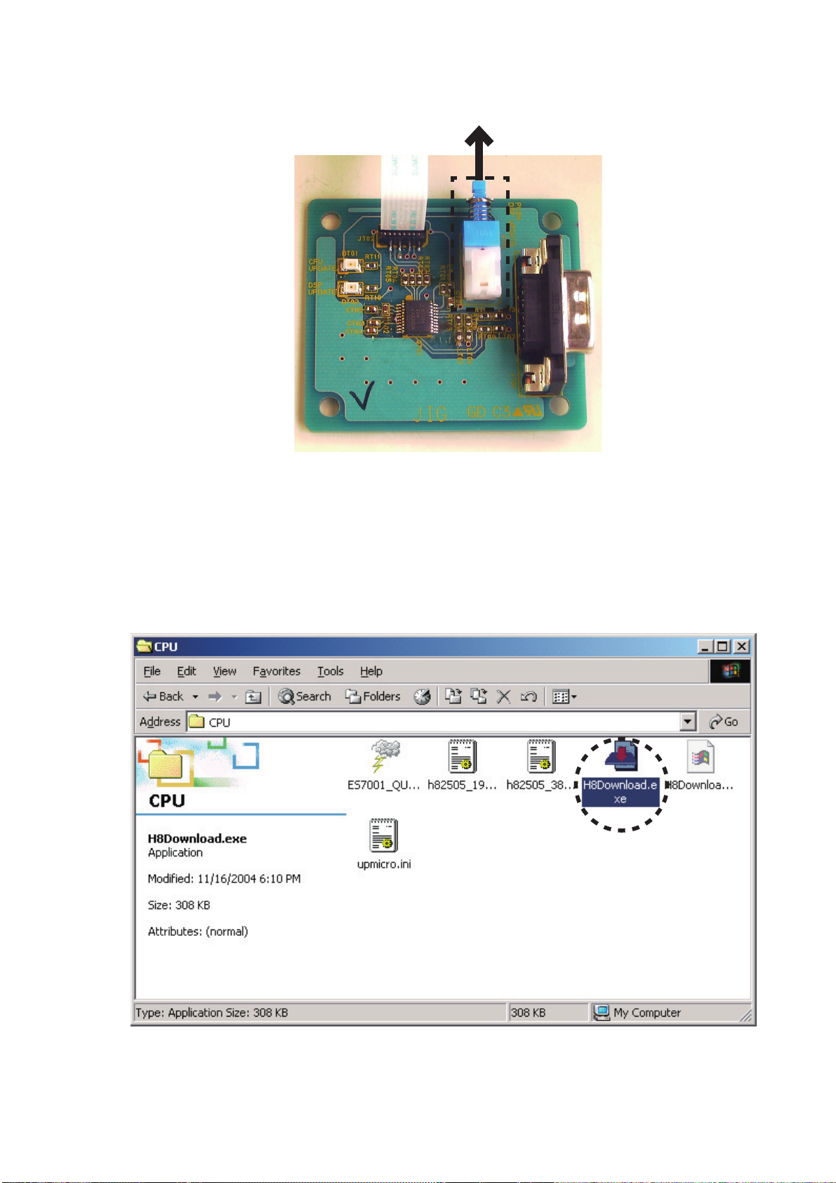
5. Double click H8Download.exe, and launch "marantz
firmware upgrade program".
4. 電源ケーブルを本機に接続します。接続冶具のLED(DT01)
が緑に点灯します。
注意 : 本機はブートモードになり、本機のLEDディスプレイ、
LEDは点灯しません。
5. PCからH8Download.exeをダブルクリックして"marantz
firmware upgrade program"
を起動させます。
25

6. Click Set ports.
6. Set Portsをクリックします。
7. Choose the COM Port No.
8. Click other files... from Information file for the micro
processor and the baud rate.
7. COMポート番号を選択します。
8. Information file for the micro processor and the baud
内のother files…をクリックします。
rate
26
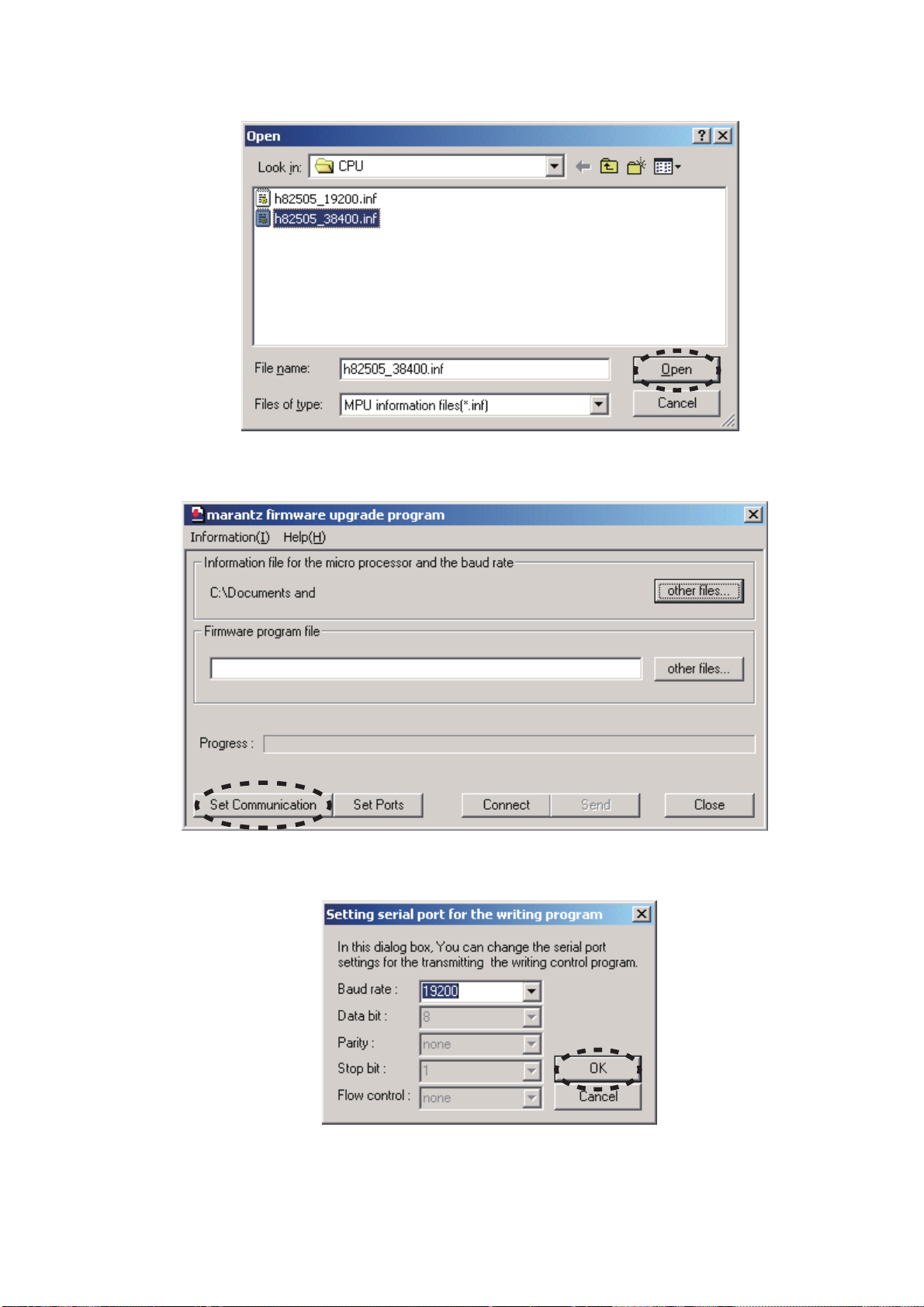
9. Choose h82505_38400.inf. And click Open.
9. h82505_38400.infを選択し、Openをクリックします。
10. Click Set Communication.
11. Choose 19200 in the Baud rate. And click OK.
10. Set Communicationをクリックします。
11. Baud rateから19200を選択し、OKをクリックします。
27
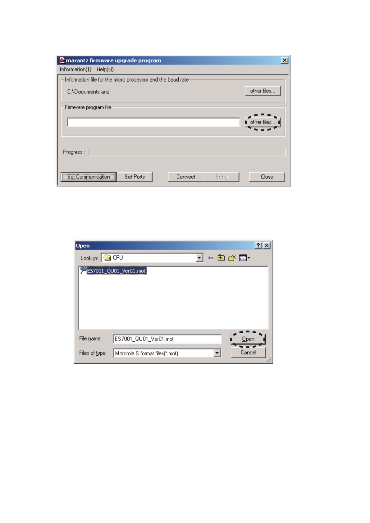
12. Click other files... from Firmware program file.
12. Firmware program file内のother files...をクリックしま
す。
13. Choose ES7001_QU01_Ver1.mot. And click Open.
NOTE : Version number changes whenever software
released.
13. ES7001_QU01_Ver1.motを選択し、Openをクリックし
ます。
注意 : ソフトウェアの発行のたびにバージョンは変更され
ます。
28
 Loading...