

Page 1
Service
CDR510 /F1B/N1B/U1B
Manual
SECTION PAG E
1. TECHNICAL SPECIFICATIONS ...................................................................................................1
2. SERVICE HINTS AND TOOLS ..................................................................................................... 3
3. WARNING AND LASER SAFETY INSTRUCTIONS..................................................................... 4
4. ADJUSTMENT.............................................................................................................................. 5
5. TECHNICAL DESCRIPTION ........................................................................................................ 8
6. SERVICE PROCEDURE............................................................................................................. 12
7. SERVICE MODE......................................................................................................................... 14
8. WIRING DIAGRAM ..................................................................................................................... 15
9. BLOCK DIAGRAM ...................................................................................................................... 17
10. SCHEMATIC DIAGRAM.............................................................................................................. 19
11. PARTS LOCATION...................................................................................................................... 39
12. IC DATA ....................................................................................................................................... 43
13. EXPLODED VIEW AND PARTS LIST......................................................................................... 53
14. ELECTRICAL PARTS LIST......................................................................................................... 57
POWER
IR
CD RECORDER/CD PLAYER CDR510
Recordable
ReWritable
CDPLAY MODECDR
REC LEVEL/SELECT
REC.
MENU/
ERASE
MODE
STORE
DELETE
CANCL/
FINAL
INPUT
DELETE
PROG
TEXTTIME
PUSH ENTER
ALBUM
TABLE OF CONTENTS
CD Recorder/CD Player
MP 3
PITCH
HEADPHONE LEVEL
010
CDR510
Please use this service manual with referring to the user guide ( D.F.U. ) without fail.
CDR510
Part no. 12AK855010
First Issue 2003.06
ecm
Page 2
MARANTZ DESIGN AND SERVICE
Using superior design and selected high grade components,
Only original
MARANTZ
parts can insure that your
MARANTZ
MARANTZ
product will continue to perform to the specifi cations for which
company has created the ultimate in stereo sound.
it is famous.
Parts for your
MARANTZ
ORDERING PARTS :
equipment are generally available to our National Marantz Subsidiary or Agent.
Parts can be ordered either by mail or by Fax.. In both cases, the correct part number has to be specifi ed.
The following information must be supplied to eliminate delays in processing your order :
1. Complete address
2. Complete part numbers and quantities required
3. Description of parts
4. Model number for which part is required
5. Way of shipment
6. Signature : any order form or Fax. must be signed, otherwise such part order will be considered as null and void.
USA
MARANTZ AMERICA, INC
1100 MAPLEWOOD DRIVE
ITASCA, IL. 60143
USA
PHONE : 630 - 741 - 0300
FAX : 630 - 741 - 0301
AMERICAS
SUPERSCOPE TECHNOLOGIES, INC.
MARANTZ PROFESSIONAL PRODUCTS
2640 WHITE OAK CIRCLE, SUITE A
AURORA, ILLINOIS 60504 USA
PHONE : 630 - 820 - 4800
FAX : 630 - 820 - 8103
EUROPE / TRADING
MARANTZ EUROPE B.V.
P. O. BOX 8744, BUILDING SILVERPOINT
BEEMDSTRAAT 11, 5653 MA EINDHOVEN
THE NETHERLANDS
PHONE : +31 - 40 - 2507844
FAX : +31 - 40 - 2507860
AUSTRALIA
TECHNICAL AUDIO GROUP PTY, LTD
43-53 Bridge Rd.,
STANMORE NSW 2048
AUSTRALIA
PHONE : +61 - (0)2 - 9519 - 0900
FAX : +61 - (0)2 - 9519 - 0600
CANADA
LENBROOK INDUSTRIES LIMITED
633 GRANITE COURT,
PICKERING, ONTARIO L1W 3K1
CANADA
PHONE : 905 - 831 - 6333
FAX : 905 - 831 - 6936
HONG KONG
Jolly ProAudio Broadcast Engineering Ltd.
UNIT 2, 10F, WAH HUNG CENTRE,
41 HUNG TO ROAD, KWUN TONG, KLN.,
HONG KONG
PHONE : 852 - 21913660
FAX : 852 - 21913990
AUSTRALIA
QualiFi Pty Ltd,
24 LIONEL ROAD,
MT. WAVERLEY VIC 3149
AUSTRALIA
PHONE : +61 - (0)3 - 9543 - 1522
FAX : +61 - (0)3 - 9543 - 3677
NEW ZEALAND
WILDASH AUDIO SYSTEMS NZ
14 MALVERN ROAD MT ALBERT
AUCKLAND NEW ZEALAND
PHONE : +64 - 9 - 8451958
FAX : +64 - 9 - 8463554
JAPAN
MARANTZ JAPAN, INC.
35- 1, 7- CHOME, SAGAMIONO
SAGAMIHARA - SHI, KANAGAWA
JAPAN 228-8505
PHONE : +81 42 748 1013
FAX : +81 42 741 9190
Technical
THAILAND
MRZ STANDARD CO., LTD
746 - 754 MAHACHAI ROAD.,
WANGBURAPAPIROM, PHRANAKORN,
BANGKOK, 10200 THAILAND
PHONE : +66 - 2 - 222 9181
FAX : +66 - 2 - 224 6795
TAIWAN
PAI- YUING CO., LTD.
6 TH FL NO, 148 SUNG KIANG ROAD,
TAIPEI, 10429, TAIWAN R.O.C.
PHONE : +886 - 2 - 25221304
FAX : +886 - 2 - 25630415
SHOCK, FIRE HAZARD SERVICE TEST :
SINGAPORE
WO KEE HONG DISTRIBUTION PTE LTD
130 JOO SENG ROAD
#03-02 OLIVINE BUILDING
SINGAPORE 368357
PHONE : +65 6858 5535 / +65 6381 8621
FAX : +65 6858 6078
MALAYSIA
WO KEE HONG ELECTRONICS SDN. BHD.
2ND FLOOR BANGUNAN INFINITE CENTRE
LOT 1, JALAN 13/6, 46200 PETALING JAYA
SELANGOR DARUL EHSAN, MALAYSIA
PHONE : +60 - 3 - 7954 8088
FAX : +60 - 3 - 7954 7088
KOREA
MK ENTERPRISES LTD.
ROOM 604/605, ELECTRO-OFFICETEL, 16-58,
3GA, HANGANG-RO, YONGSAN-KU, SEOUL
KOREA
PHONE : +822 - 3232 - 155
FAX : +822 - 3232 - 154
CAUTION : After servicing this appliance and prior to returning to customer, measure the resistance between either primary AC
cord connector pins ( with unit NOT connected to AC mains and its Power switch ON ), and the face or Front Panel of product and
controls and chassis bottom.
Any resistance measurement less than 1 Megohms should cause unit to be repaired or corrected before AC power is applied, and
verifi ed before it is return to the user/customer.
Ref. UL Standard No. 1492.
In case of diffi culties, do not hesitate to contact the Technical
Department at above mentioned address.
030307MIT
Page 3

1. TECHNICAL SPECIFICATIONS
GENERAL
System ................................................................................................................ Compact disc digital audio
Number of channels.......................................................................................................................2 (stereo)
Applicable discs .....................................................................................................CD, CD-R, CD-RW, MP3
Power Requirement [F] ..................................................................................................AC 100 V 50/60 Hz
[N] .........................................................................................AC 100 - 240 V 50/60 Hz
[U] .......................................................................................................AC 120 V 60 Hz
Power Consumption............................................................................................................................. 20 W
Operating Temperature
Dimension (MAX)
Width...........................................................................................................................483 mm (19 inches)
Height ................................................................................................................ 100 mm (3-15/16 inches)
Depth ................................................................................................................. 340 mm (13-7/16 inches)
Weight ..................................................................................................................................5.4 kg (11.9 lbs)
AUDIO
ADC ................................................................................ 3rd-order Sigma-Delta ADC 128 x over sampling
DAC ............................................................................................... Filter Stream DAC 128 x over sampling
Frequency Response............................................................................................................ 20 Hz - 20 kHz
CDR OUT
Playback S/N .................................................................................................................................... 96 dB
Playback Dynamic Range................................................................................................................ 85 dB
Payback Total Harmonic Distortion ...................................................................................................82 dB
CD OUT
Play back S/N .................................................................................................................................103 dB
Play back Dynamic Range................................................................................................................ 96 dB
Play back Total Harmonic Distortion .................................................................................................91 dB
Analog Output Voltage .................................................................................................................... 2.0 Vrms
Analog Recording S/N.......................................................................................................................... 85 dB
Analog Recording Dynamic Range...................................................................................................... 82 dB
Analog Recording Total Harmonic Distortion .......................................................................................80 dB
Digital Coaxial Output ........................................................................................................0.5 V (p-p) / 75 Ω
Digital Optical Output ......................................................................................................................- 20 dBm
Headphone................................................................................................................0 - 5 Vrms / 8 - 2000 Ω
Recording values for line input
Digital Coaxial Input (automatic sample rate conversion).................... 32 / 44.1 / 48 kHz (11 kHz - 56 kHz)
Digital Optical Input (automatic sample rate conversion)..................... 32 / 44.1 / 48 kHz (11 kHz - 56 kHz)
Analog Input Sensitivity (Unbalanced) ........................................................................... 500 mVrms / 50 kΩ
(Balanced....................................................................... 0 dBu to + 22 dBu / 50 kΩ
(default setting : +16dBu/50 k )
ACCESSORIES
Remote Control Unit RC2100DR ................................................................................................................ 1
AA-size batteries......................................................................................................................................... 2
AC power cord............................................................................................................................................. 1
Audio cable (white and red)........................................................................................................................... 2
RC-5 cable (orange)...................................................................................................................................... 1
1
Page 4
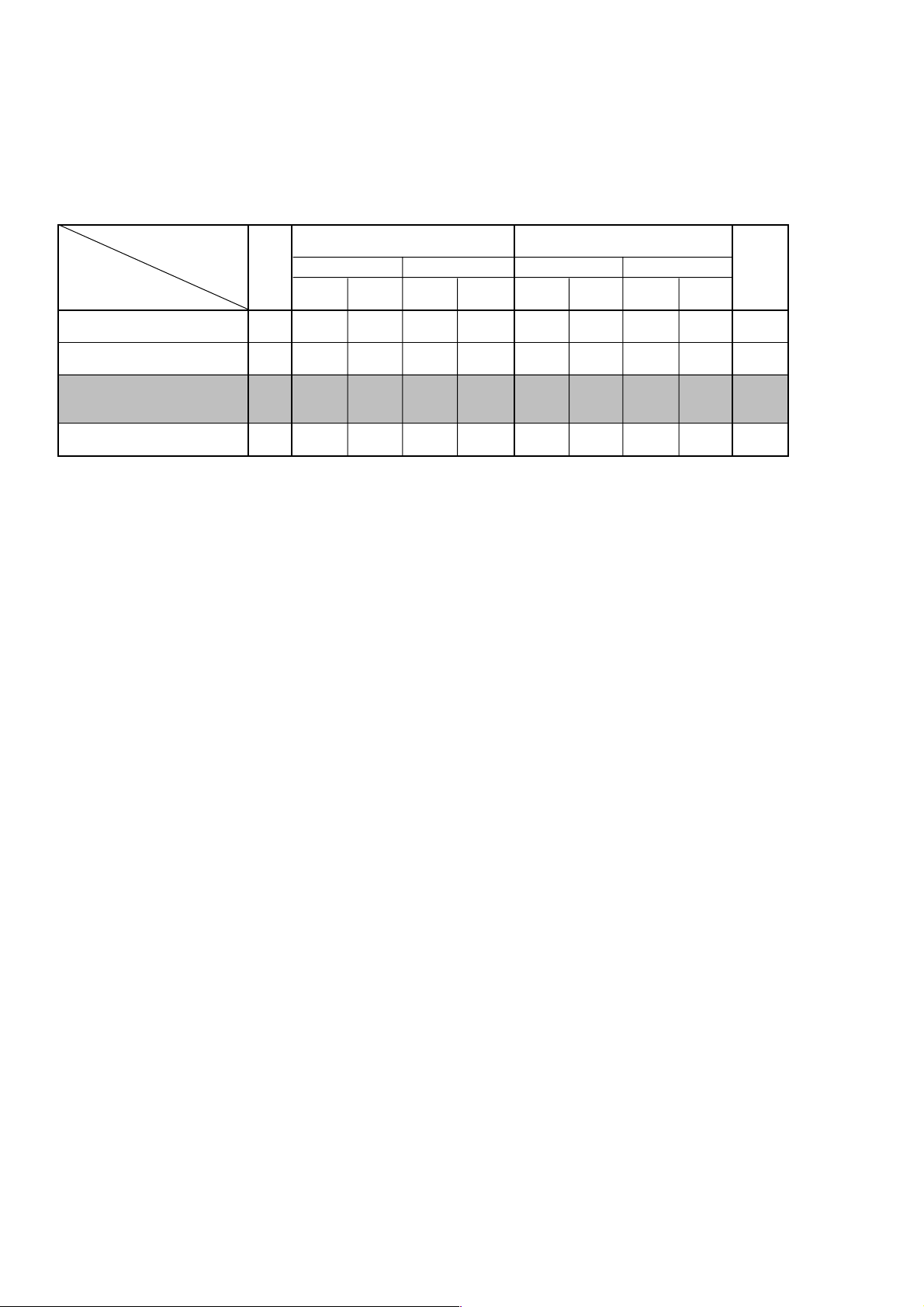
Playback & Recording and Disc
The CDR510 is the professional version of a CD recorder, this means that the SCMS (Serial Copy Management System)
is included. The CDR510 can only record on the Audio and PC CDRs.
The CDR510 is suitable for recording and playback of CD-RW discs (CD-ReWritable disc).
Disc
Consumer Disc
CD
Player/Recorder
Audio CD Player
Current products Ex:CD-17
Audio CD Player
CD-RW playback Ex:CD-17MK II
CD-RW Recorder
For Professional
Ex:CDR510/500/631
CD-RW Recorder
For Consumer Ex:DR6050
Finalized
PP no P no no no no no -
PP no P no P no P no -
P P P/R P P/R P/R P/R P/R P/R no
P P P/R P P P/R P/R P YES
Consumer : For Digital Audio
Professional : For General use (Including PC)
P : Playback
R : Recording
CDR
non
Finalized
CD-RW
Professional Disc
Finalized Finalized
non
Finalized
Consumer Disc
Finalized
non
Finalized
Professional Disc
P
SCMS
non
Finalized
2
Page 5
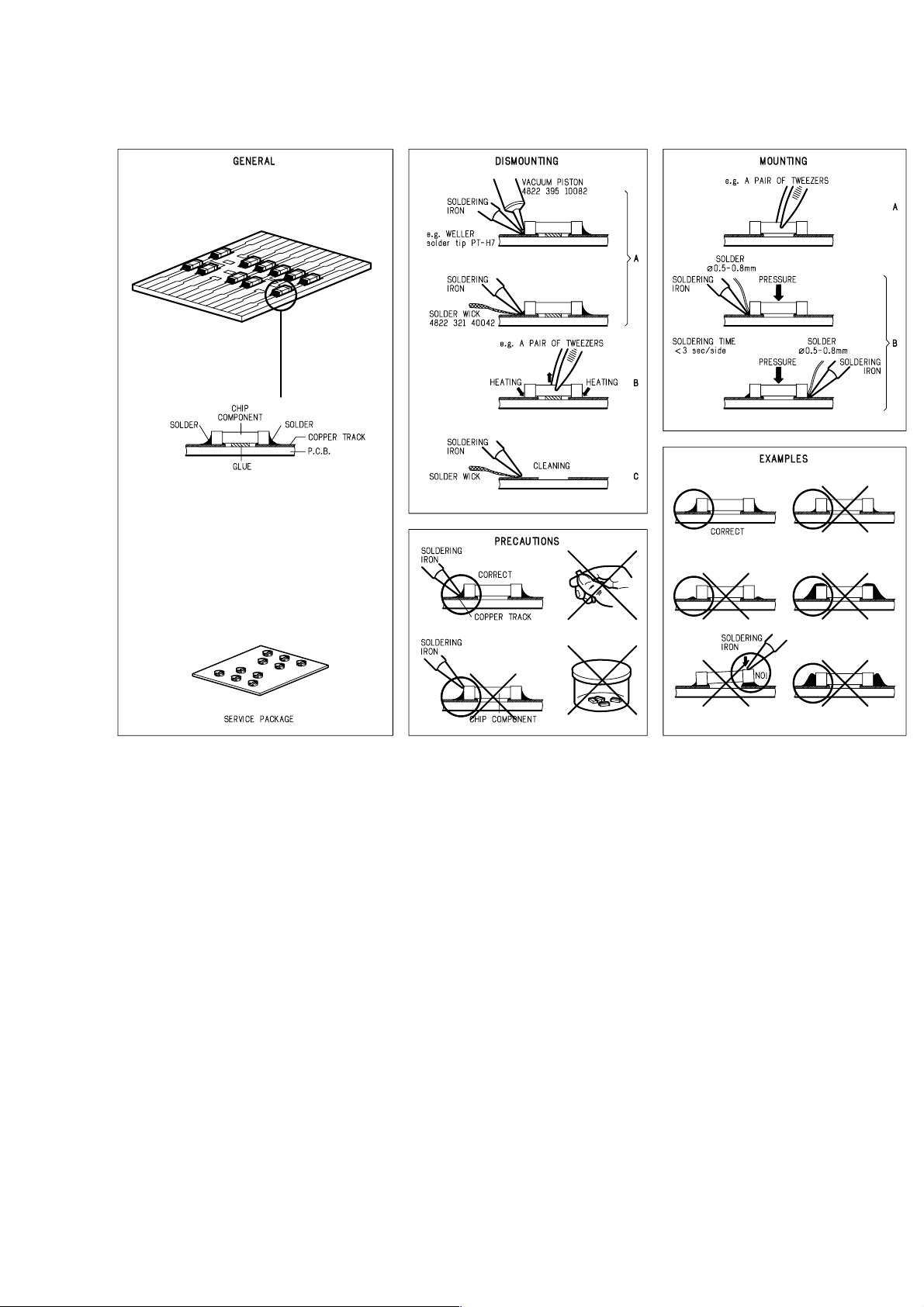
2. SERVICE HINTS AND TOOLS
SERVICE HINTS
SERVICE TOOLS
Audio signals disc 4822 397 30184
Disc without errors (SBC444)+Disc with DO errors,
black spots and fingerprints (SBC444A) 4822 397 30245
Disc (65 min 1kHz) without no pause 4822 397 30155
Max. diameter disc (58.0 mm) 4822 397 60141
13th order filter
3
4822 395 30204
Page 6
3. WARNING AND LASER SAFETY INSTRUCTIONS
GB
WARNING
All ICs and many other semi-conductors are
susceptible to electrostatic discharges (ESD).
Careless handling during repair can reduce
life drastically.
When repairing, make sure that you are
connected with the same potential as the
mass of the set via a wrist wrap with
resistance.
Keep components and tools also at this
potential.
F
ATTENTION
D
WARNUNG
I
WAARSCHUWING
AVVERTIMENTO
NL
Alle IC’s en vele andere halfgeleiders zijn
gevoelig voor elektrostatische ontladingen
(ESD).
Onzorgvuldig behandelen tijdens reparatie
kan de levensduur drastisch doen
verminderen.
Zorg ervoor dat u tijdens reparatie via een
polsband met weerstand verbonden bent met
hetzelfde potentiaal als de massa van het
apparaat.
Houd componenten en hulpmiddelen ook op
ditzelfde potentiaal.
Tous les IC et beaucoup d’autres semiconducteurs sont sensibles aux décharges
statiques (ESD).
Leur longévité pourrait être considérablement
écourtée par le fait qu’aucune précaution
n’est prise a leur manipulation.
Lors de réparations, s’assurer de bien être
relié au même potentiel que la masse de
l’appareil et enfiler le bracelet serti d’une
résistance de sécurité.
Veiller a ce que les composants ainsi que les
outils que l’on utilise soient également a ce
potentiel.
GB
Safety regulations require that the set be restored to its original condition
and that parts which are identical with those specified be used.
NL
Veiligheidsbepalingen vereisen, dat het apparaat in zijn oorspronkelijke
toestand wordt terug gebracht en dat onderdelen, identiek aan de
gespecifieerde worden toegepast.
Alle IC und viele andere Halbleiter sind
empfindlich gegen elektrostatische
Entladungen (ESD).
Unsorgfältige Behandlung bei der Reparatur
kann die Lebensdauer drastisch vermindern.
Sorgen sie dafür, das Sie im Reparaturfall
über ein Pulsarmband mit Widerstand mit
dem Massepotential des Gerätes verbunden
sind.
Halten Sie Bauteile und Hilfsmittel ebenfalls
auf diesem Potential.
D
Bei jeder Reparatur sind die geltenden Sicherheitsvorschriften zu beachten.
Der Originalzustand des Gerats darf nicht verandert werden.
Fur Reparaturen sind Original-Ersatzteile zu verwenden.
I
Le norme di sicurezza esigono che l’apparecchio venga rimesso nelle
condizioni originali e che siano utilizzati pezzi di ricambiago idetici a quelli
specificati.
Tutti IC e parecchi semi-conduttori sono
sensibili alle scariche statiche (ESD).
La loro longevita potrebbe essere fortemente
ridatta in caso di non osservazione della piu
grande cauzione alla loro manipolazione.
Durante le riparazioni occorre quindi essere
collegato allo stesso potenziale che quello
della massa dell’apparecchio tramite un
braccialetto a resistenza.
Assicurarsi che i componenti e anche gli
utensili con quali si lavora siano anche a
questo potenziale.
F
“Pour votre sécurité, ces documents
doivent être utilisés par des
spécialistes agrées, seuls habilités à
réparer votre appareil en panne.”
Les normes de sécurité exigent que l’appareil soit remis a l’état d’origine et
que soient utilisées les pièces de rechange identiques à celles spécifiées.
LASER SAFETY
This unit employs a laser. Only a qualified service person should remove the cover or attempt to service this
device, due to possible eye injury.
USE OF CONTROLS OR ADJUSTMENTS OR PERFORMANCE OF PROCEDURE OTHER THAN THOSE
SPECIFIED HEREIN MAY RESULT IN HAZARDOUS RADIATION EXPOSURE.
AVOID DIRECT EXPOSURE TO BEAM
WARNING
The use of optical instruments with this product will increase eye hazard.
Repair handling should take place as much as possible with a disc loaded inside the player
WARNING LOCATION: INSIDE ON LASER COVERSHIELD
CAUTION VISIBLE AND INVISIBLE LASER RADIATION WHEN OPEN AVOID EXPOSURE TO BEAM
ADVARSEL SYNLIG OG USYNLIG LASERSTRÅLING VED ÅBNING UNDGÅ UDS
ADVARSEL SYNLIG OG USYNLIG LASERSTRÅLING NÅR DEKSEL Å PNES UNNGÅ EKSPONERING FOR STRÅLEN
VARNING SYNLIG OCH OSYNLIG LASERSTRÅLNING NÄR DENNA DEL ÄR ÖPPNAD BETRAKTA EJ STRÅLEN
VARO! AVATT AESSA OLET ALTTIINA NÄKYVÄLLE JA NÄKYMÄTTÖMÄLLE LASER SÄTEILYLLE. ÄLÄ KATSO SÄTEESEEN
VORSICHT SICHTBARE UND UNSICHTBARE LASERSTRAHLUNG WENN ABDECKUNG GEÖFFNET NICHT DEM STRAHL AUSSETSEN
DANGER VISIBLE AND INVISIBLE LASER RADIATION WHEN OPEN AVOID DIRECT EXPOSURE TO BEAM
ATTENTION RAYONNEMENT LASER VISIBLE ET INVISIBLE EN CAS D'OUVERTURE EXPOSITION DANGEREUSE AU FAISCEAU
Æ
TTELSE FOR STRÅLING
4
Page 7
4. ADJUSTMENTS
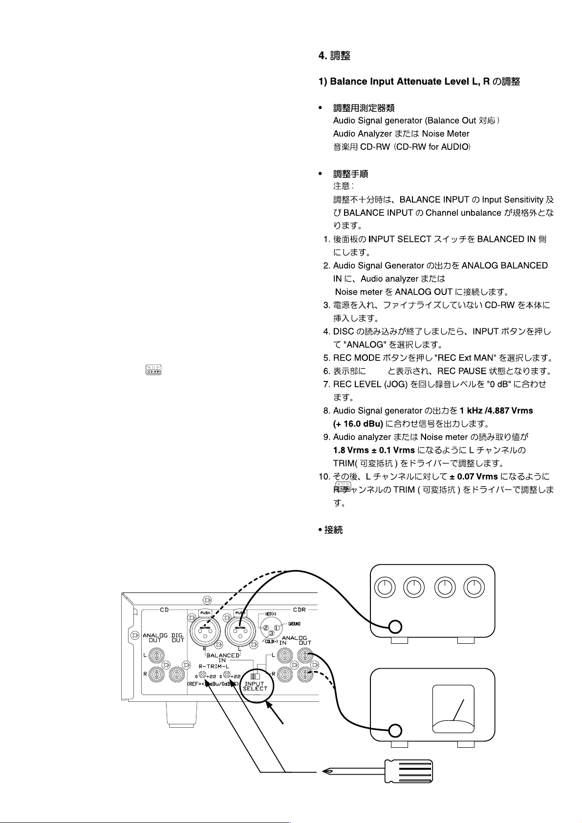
1) Balance Input Attenuate Level L, R Adjustment
• Necessary Equipment
Audio Signal generator (Correspond to Balance Out )
Audio Analyzer or Noise Meter
CD-RW for Audio recording
• Adjustment procedure
Attention :
When adjustment is insuffi cient, Input Sensitivity and
Channel unbalance of BALANCE INPUT become Spec out.
1. Set INPUT SELECT switch to "BALANCED IN"
2. Connect output of Audio Signal Generator to ANALOG
BALANCED IN. Connect Audio analyzer or Noise meter to
ANALOG OUT.
3. Press POWER button to turn on the unit, insert a
un-fi nalized CD-RW disc to CD-Recorder.
4. The display show the type of disc you inserted. Press
INPUT button and select "ANALOG". (Press INPUT button
repeatedly until the selected "ANALOG" appears the
display)
5. Press REC MODE Button and select "REC Ext MAN".
6. The display show
mode.
7. Turn REC LEVEL(JOG) knob , and adjust recording level to
"0dB"
8. Adjust output level of Audio Signal Generator to "1 kHz /
4.887 Vrms (+ 16.0 dBu)", and a signal is outputted.
9. Adjust TRIM (variable resistance) of the L channel with the
driver so that the reading numerical value of analyzer or
Noise meter to become "1.8 Vrms ± 0.1 Vrms".
10. After that, adjust TRIM of the R channel with the driver to
become "± 0.07 Vrms "toward the L channel.
, and the unit become REC/PAUSE
• Connection
Audio Signal Generator
OUTPUT
1 kHz / 4.887 Vrms
Audio analizer or Noise meter
INPUT
Switch to
BALANCED IN
5
Page 8
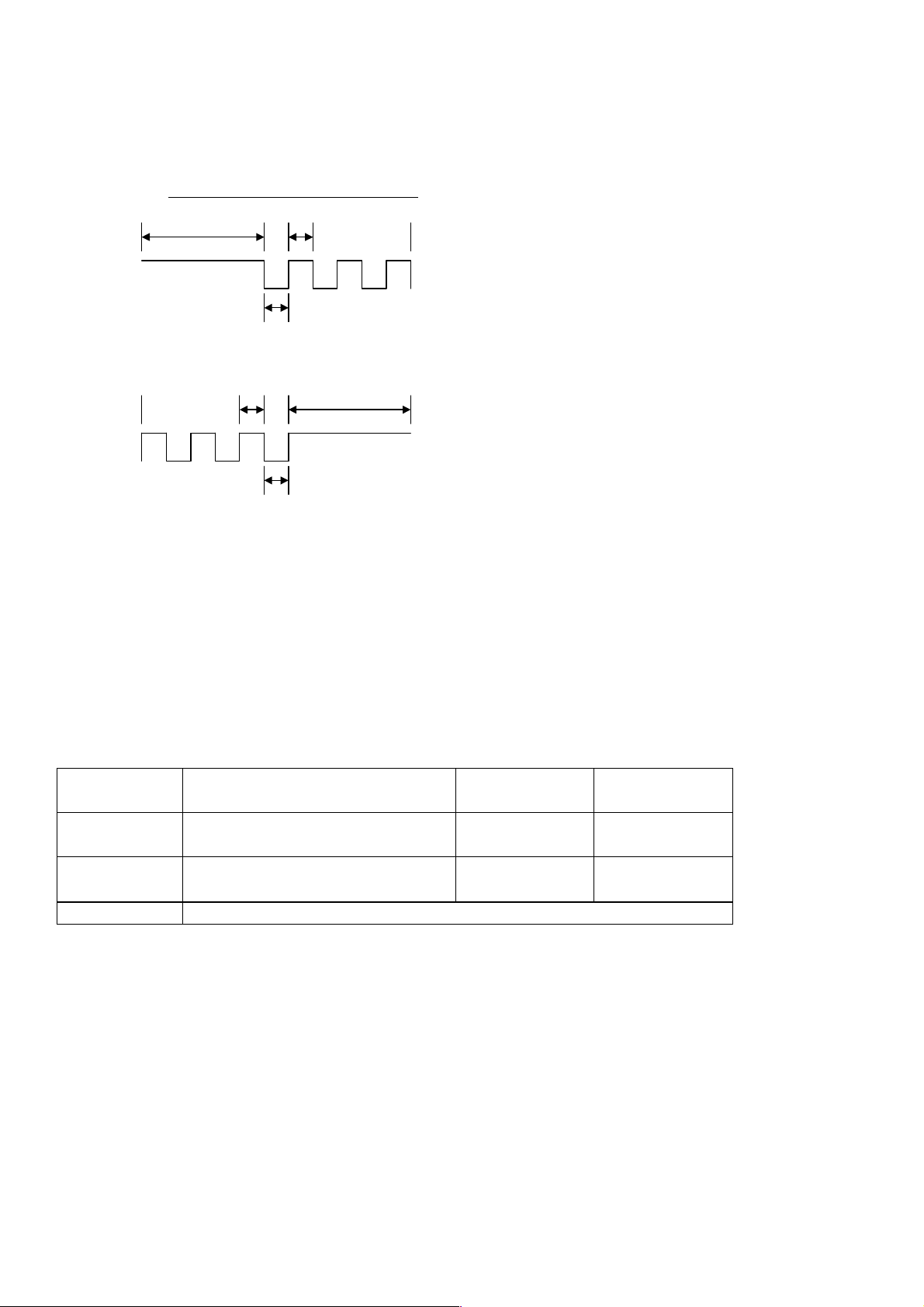
2) Disk Tray Open/Close Speed Adjustment
Open/Close speed of the tray can be changed.
When vibration occurs upon tray open/close and some unusual behavior happens,
change the tray speed to stop vibration.
Description of the terms displayed on FL
start T-On Time open
T-Push Tm
Tray open
T-OffTim
start T-On Time close
T-Push Tm
Tray close
T-OffTim
<Vibration on Disc Tray Open / Close>
Step 1. With pressing CDR STOP and CDR PLAY/PAUSE buttons, press POWER button.
Step 2. Press REC LEVEL/SELECT(PUSH ENTER) button.
"T-OnTime 015" (means Tray On Time 015ms default) is displayed.
Tu rn REC LEVEL/SELECT to change tray open/close speed from 000 to 255ms. Turn the number
smaller to make the open/close speed slower. Turn the number bigger to make the speed faster. Set
bigger number to stop the tray vibration. But the open/close speed becomes faster.
Press REC LEVEL/SELECT button again. The display changes as shown below so you can change
other parameters for the open/close speed.
T-PushTm
DC driving time on Tray open operation.
Tray is DC driven at start opening.
Then Tray is driven by pulse.
Time can be set between 0-2550ms.
T-On Time
Duration time of High in pulse drive.
Time can be set between 0-255ms.
T-OffTim
Duration time of Low in pulse drive.
Time can be set between 0-255ms.
T-PullCt
The number of pulses on Tray close
operation.
Display
(Default Setting)
T- OffTim 003
T- PushTm 070
T- PullCt 040 When disc clamp miss happens. Set smaller number to make it better.
Step 3. Press REC LEVEL/SELECT button to complete adjustment.
Step 4. Press CD STOP button to store the settings in memory.
To reset all the settings to default status, press number 0 button in Service Mode 0
(Display : VER_*-** P00 ). When miss-operated, press number 0 button to retry.
When open/close speed is too fast.
Note) 001, 002, 003 cannot be set.
When vibration cannot be stopped
by adjusting T-OnTime.
Description Bigger Number Smaller Number
open/close speed
becomes faster
open/close speed
becomes slower
open/close speed
becomes slower
open/close speed
becomes faster
6
Page 9
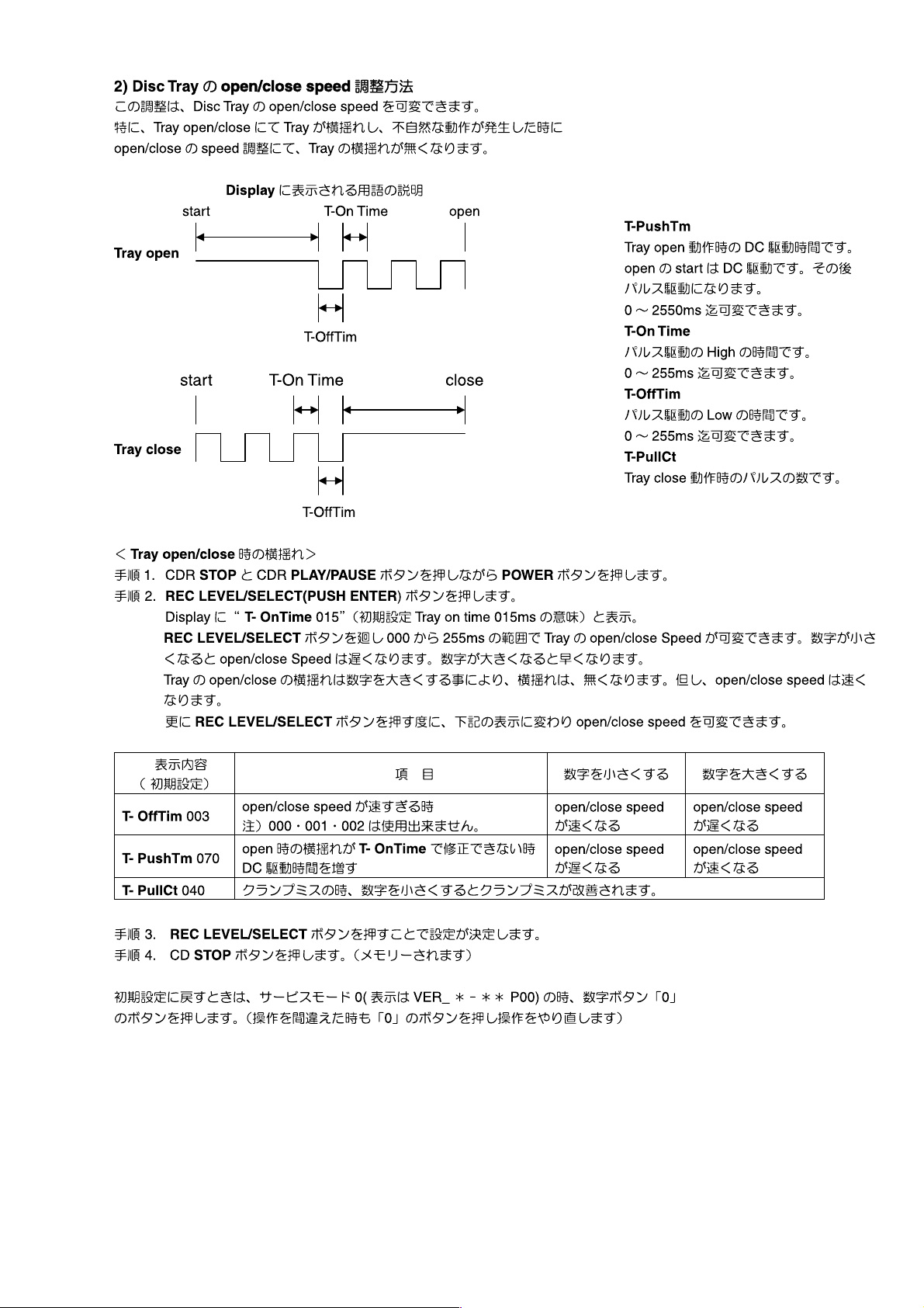
T-Push Tm
T-Push Tm
7
Page 10
5. TECHNICAL DESCRIPTION
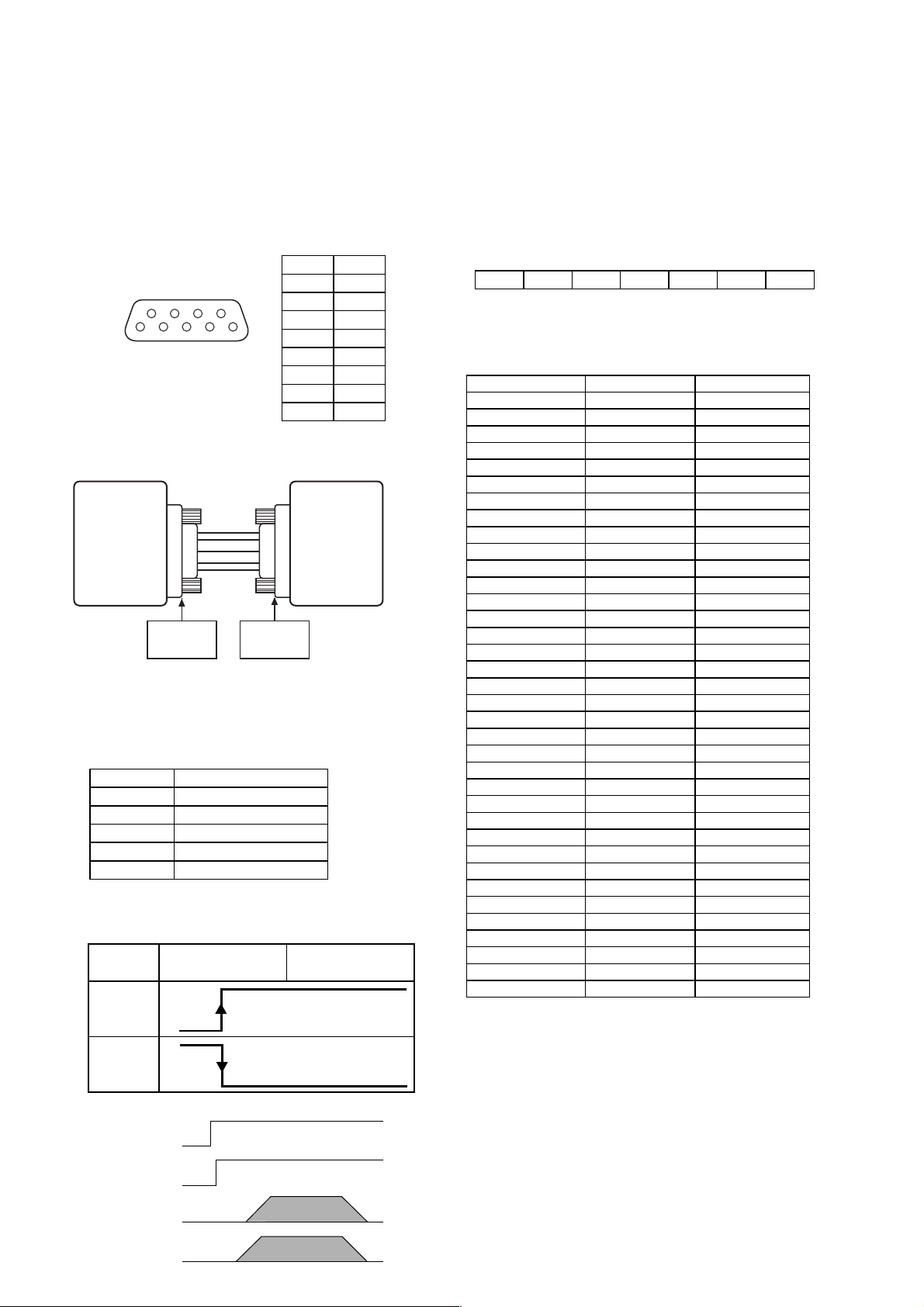
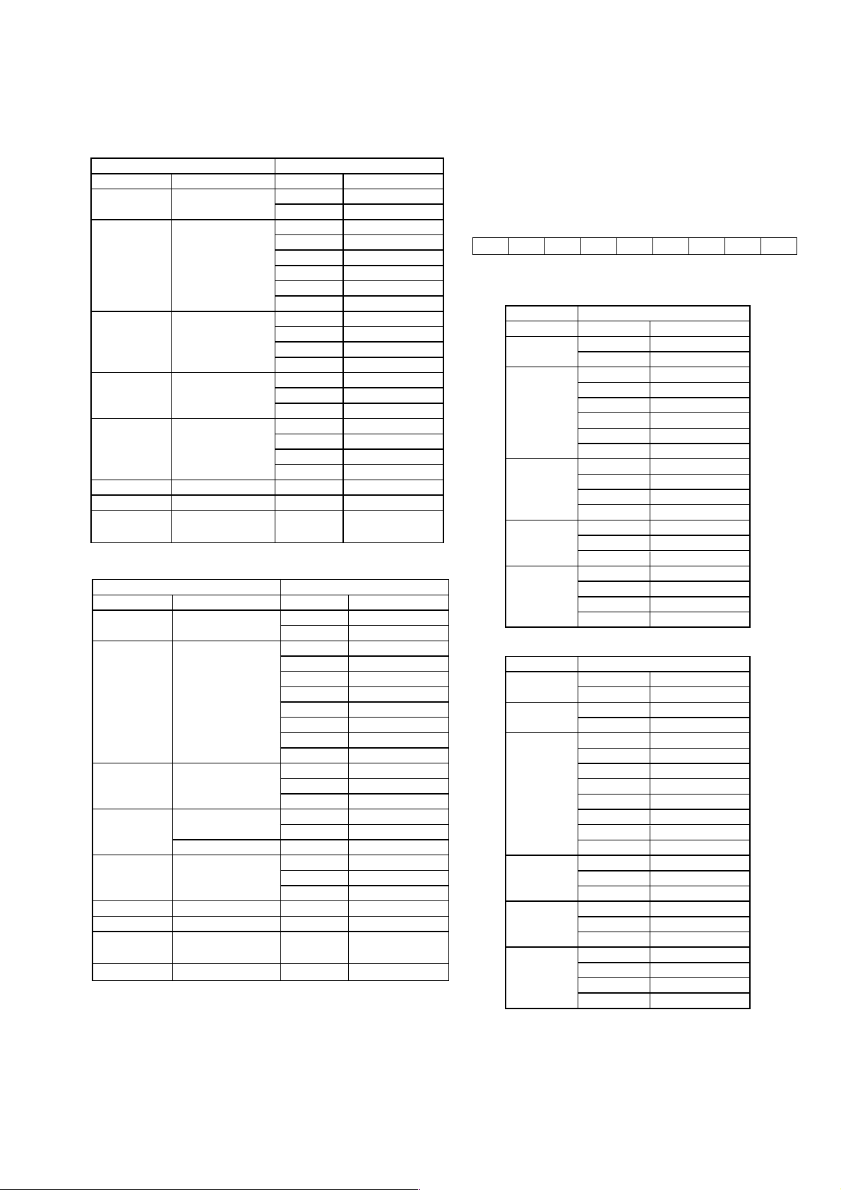
How to use the RS-232C connector
This input/output connector (D-Sub 9-pin female) is used for
RS-232C external control.
A straight cable available on the market can be connected to
this connector to exercise external control and send status
information.
• Connector pin assignment
69
51
• RS232C Connection
CDR510 Typical HOST
Transmit Data
Receive Data
Ground
RS in
CS out
2
3
5
7
8
D-Sub 9 Pin
(male)
D-Sub 9 Pin
The wiring requirements for a 9 pin to 9 pin serial
con nec tion, are a male to female straight cable.
• RS-232C physical specifi cations
Cable Straight cable
Baud rate 9600 bps
Data bits 8 bits
Parity bit None
Stop bit 1 bit
Flow control CS/RS Hardware Flow
CS/RS Hardware Flow Control
Typical Host
RTS send
No Busy
(Normal)
Busy H
H
L
1NC
2TX
3RX
4NC
5 GND
6NC
7RTS
8 CTS
9NC
2
Rx Data
3
Tx Data
5
Ground
7
RTS send
8
CTS receive
(female)
CDR510CS out
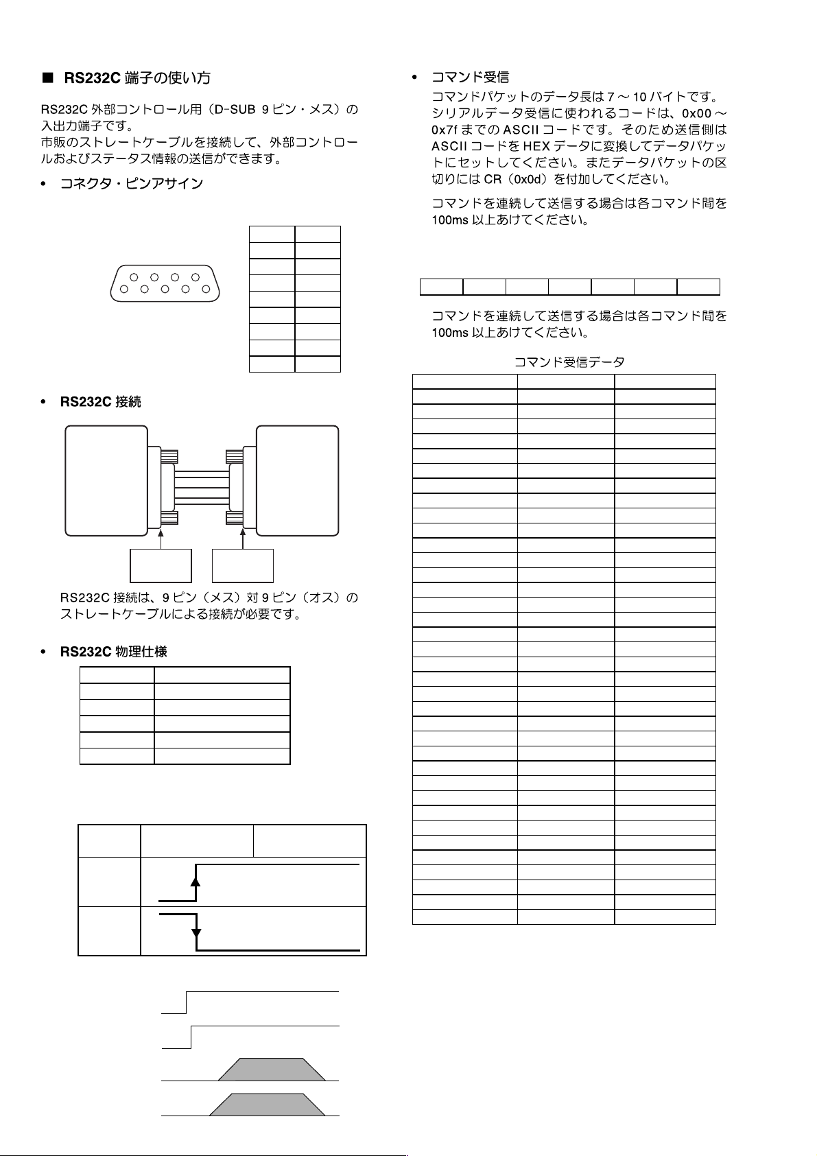
• Command reception
The command packets have a data length of 7 - 10 bytes.
ASCII codes from 0x00 to 0x7f are used to receive serial
data. At the transmission end, therefore, take steps to
convert the ASCII codes into HEX data to set the data in
the data packets. CR (0x0d) is added as the data packet
delimiter.
:
Example
"0" (code
[@][1][2][0][0][0][CR]
0x40 0x31 0x32 0x30 0x30 0x30 0x0d
When transmitting commands consecutively, put more
than 100ms blank between commands.
Request Command CD Command CDR Command
0 "@12000"+CR "@12600"+CR
1 "@12001"CR "@12601"+CR
2 "@12002"+CR "@12602"+CR
3 "@12003"+CR "@12603"+CR
4 "@12004"+CR "@12604"+CR
5 "@12005"+CR "@12605"+CR
6 "@12006"+CR "@12606"+CR
7 "@12007"+CR "@12607"+CR
8 "@12008"+CR "@12608"+CR
9 "@12009"+CR "@12609"+CR
Display "@12015"+CR "@12615"+CR
Scroll "@12011"+CR "@12611"+CR
Repeat "@12029"+CR "@12629"+CR
Next "@12032"+CR "@12632"+CR
Previous "@12033"+CR "@12633"+CR
Pitch Reset "@12037"+CR Pitch Up Start "@12038"+CR Pitch Up Stop "@1203801"+CR -
Pitch Down Start "@12039"+CR Pitch Down Stop "@1203901"+CR -
Program "@12036"+CR "@12636"+CR
AMS "@12043"+CR "@12643"+CR
Pause "@12048"+CR "@12648"+CR
Cancel/Delete "@12049"+CR "@12649"+CR
Fast Backward Start "@12050"+CR "@12650"+CR
Fast Backward Stop "@1205001"+CR "@1265001"+CR
Fast Forward Start "@12052"+CR "@12652"+CR
Fast Forward Stop "@1205201"+CR "@1265201"+CR
Play "@12053"+CR "@12653"+CR
Stop "@12054"+CR "@12654"+CR
Random "@12028"+CR "@12647"+CR
Store/Menu "@12082"+CR "@12642"+CR
Enter "@12087"+CR "@12687"+CR
Select CD "@12063"+CR -
Select CDR - "@12663"+CR
Track Inc. - "@126114"+CR
@1
2000
)
Received command data
Timing chart
L
RTS
CTS
RxD
TxD
8
Page 11
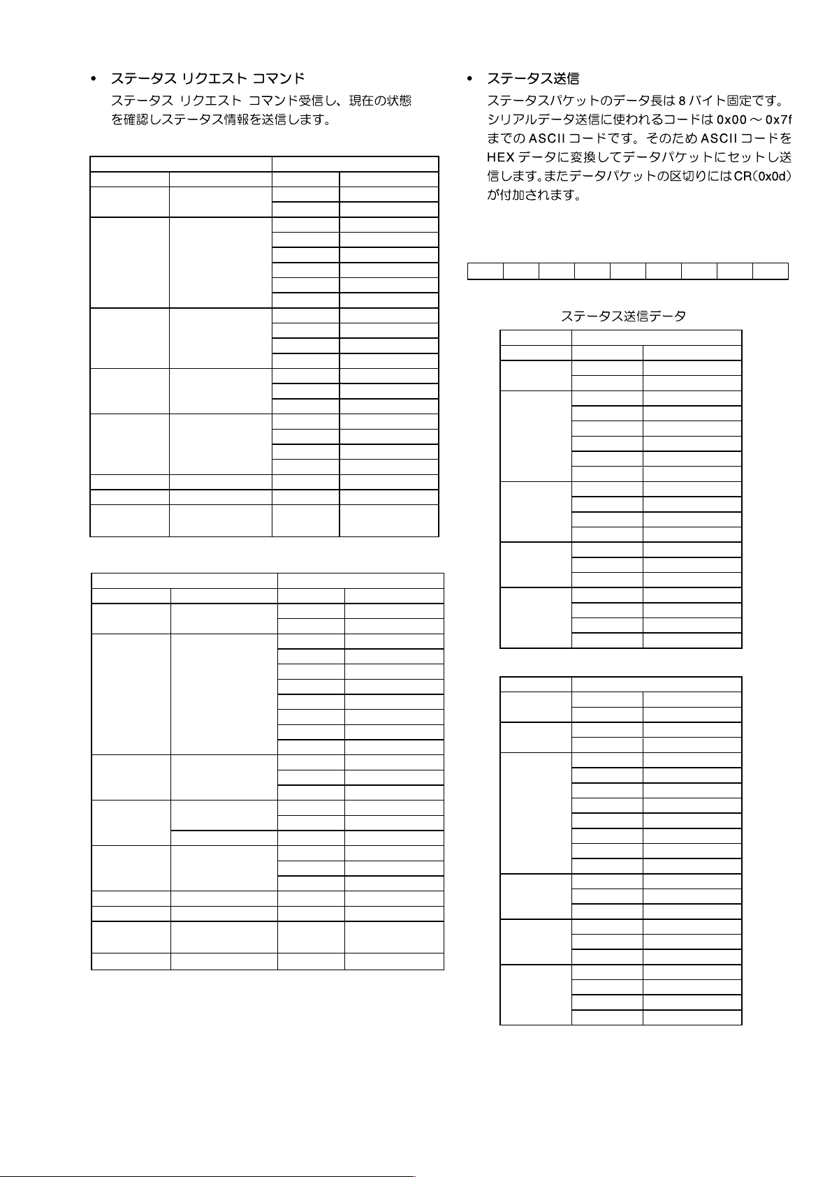
• Status request commands
The following status request commands are received
to confi rm the current status, the status information is
transmitted
Request Command for CD Response from CD
Power "@1?20POWE"+CR Power On "@120PRON"+CR
Tray Mode "@1?20TRAY"+CR
Play Mode "@1?20PLAY"+CR
Disc "@1?20DISC"+CR
Repeat Mode "@1?20RPTM"+CR
Time Mode "@1?20TMOD"+CR
Album "@1?20ALBU"+CR "@120Axxx"+CR
Track "@1?20TRAC"+CR "@120Txxx"+CR
Current Display
Time
Request Command for CDR Response from CDR
Power "@1?26POWE"+CR Power On "@126PRON"+CR
Tray Mode "@1?26TRAY"+CR
Play Mode "@1?26PLAY"+CR
Disc "@1?26DISC"+CR
Repeat Mode
Time Mode "@1?26TMOD"+CR
Track "@1?26TRAC"+CR "@126Txxx"+CR
Current Display
Time
"@1?20TIME"+CR "@120xxxx"+CR
"@1?26RPTM"+CR
"@1?26TIME"+CR "@126xxxx"+CR
Open "@120OPEN"+CR
Close "@120CLOS"+CR
Toc Reading "@120TOCR"+CR
Stop "@120STOP"+CR
Play "@120PLAY"+CR
Pause "@120PASE"+CR
FF "@120FASF"+CR
REW "@120FASR"+CR
No Disc "@120NODI"+CR
ERROR "@120ERDI"+CR
CDDA "@120CDDI"+CR
MP3 "@120MPDI"+CR
OFF "@120RTOF"+CR
ONE "@120RTON"+CR
ALL "@120RTAL"+CR
Track "@120TTRA"+CR
Track Rem "@120TTRE"+CR
Total Rem "@120TREM"+CR
Total Lap "@120TTLA"+CR
Open "@126OPEN"+CR
Close "@126CLOS"+CR
Toc Reading "@126TOCR"+CR
Stop "@126STOP"+CR
Play "@126PLAY"+CR
Pause "@126PASE"+CR
FF "@126FASF"+CR
REW "@126FASR"+CR
Rec "@126RECO"+CR
Rec Pause "@126RECP"+CR
No Disc "@126NODI"+CR
ERROR "@126ERDI"+CR
CDDA "@126CDDI"+CR
OFF "@126RTOF"+CR
ONE "@126RTON"+CR
ALL "@126RTAL"+CR
Track "@126TTRA"+CR
Track Rem "@126TTRE"+CR
Total Rem "@126TREM"+CR
Total Lap "@126TTLA"+CR
• Status transmission
The status packets have a fi xed data length of 8 bytes.
ASCII codes from 0x00 to 0x7f are used to transmit serial
data. For this reason, the ASCII codes are converted
into HEX data before the data is set in the data packets
and transmitted. CR (0x0d) is added as the data packet
delimiter.
Example
1:
"Power On" (code @120PRON
[@][1][2] [0] [P][R][O][N][CR]
0x40 0x31 0x32 0x30 0x50 0x57 0x4f 0x4e 0x0d
Transmitted status data
Category Status from CD
Power Power On "@120PRON"+CR
Tray Mode
Play Mode
Disc
Repeat Mode
Time Mode
Category Status from CDR
Power
Tray Mode
Play Mode
Disc
Repeat Mode
Time Mode
Open "@120OPEN"+CR
Close "@120CLOS"+CR
Toc Reading "@120TOCR"+CR
Stop "@120STOP"+CR
Play "@120PLAY"+CR
Pause "@120PASE"+CR
FF "@120FASF"+CR
REW "@120FASR"+CR
No Disc "@120NODI"+CR
ERROR "@120ERDI"+CR
CDDA "@120CDDI"+CR
MP3 "@120MPDI"+CR
OFF "@120RTOF"+CR
ONE "@120RTON"+CR
ALL "@120RTAL"+CR
Track "@120TTRA"+CR
Track Rem "@120TTRE"+CR
Total Rem "@120TREM"+CR
Total Lap "@120TTLA"+CR
Standby "@126POFF"+CR
Power On "@126PRON"+CR
Open "@126OPEN"+CR
Close "@126CLOS"+CR
Toc Reading "@126TOCR"+CR
Stop "@126STOP"+CR
Play "@126PLAY"+CR
Pause "@126PASE"+CR
FF "@126FASF"+CR
REW "@126FASR"+CR
Rec "@126RECO"+CR
Rec Pause "@126RECP"+CR
No Disc "@126NODI"+CR
ERROR "@126ERDI"+CR
CDDA "@126CDDI"+CR
OFF "@126RTOF"+CR
ONE "@126RTON"+CR
ALL "@126RTAL"+CR
Track "@126TTRA"+CR
Track Rem "@126TTRE"+CR
Total Rem "@126TREM"+CR
Total Lap "@126TTLA"+CR
)
9
Page 12
69
51
CDR510 Typical HOST
Transmit Data
Receive Data
Ground
RS in
CS out
2
3
5
7
8
D-Sub 9 Pin
(male)
2
3
5
7
8
D-Sub 9 Pin
(female)
Rx Data
Tx Data
Ground
RTS send
CTS receive
Cable Straight cable
Baud rate 9600 bps
Data bits 8 bits
Parity bit None
Stop bit 1 bit
Flow control CS/RS Hardware Flow
CS/RS Hardware Flow Control
Typical Host
RTS send
No Busy
H
(Normal)
L
Busy H
1NC
2TX
3RX
4NC
5 GND
6NC
7RTS
8 CTS
9NC
CDR510CS out
Example: "0" (code
@1
2000
)
[@][1][2][0][0][0][CR]
0x40 0x31 0x32 0x30 0x30 0x30 0x0d
Request Command CD Command CDR Command
0 "@12000"+CR "@12600"+CR
1 "@12001"CR "@12601"+CR
2 "@12002"+CR "@12602"+CR
3 "@12003"+CR "@12603"+CR
4 "@12004"+CR "@12604"+CR
5 "@12005"+CR "@12605"+CR
6 "@12006"+CR "@12606"+CR
7 "@12007"+CR "@12607"+CR
8 "@12008"+CR "@12608"+CR
9 "@12009"+CR "@12609"+CR
Display "@12015"+CR "@12615"+CR
Scroll "@12011"+CR "@12611"+CR
Repeat "@12029"+CR "@12629"+CR
Next "@12032"+CR "@12632"+CR
Previous "@12033"+CR "@12633"+CR
Pitch Reset "@12037"+CR Pitch Up Start "@12038"+CR Pitch Up Stop "@1203801"+CR -
Pitch Down Start "@12039"+CR Pitch Down Stop "@1203901"+CR -
Program "@12036"+CR "@12636"+CR
AMS "@12043"+CR "@12643"+CR
Pause "@12048"+CR "@12648"+CR
Cancel/Delete "@12049"+CR "@12649"+CR
Fast Backward Start "@12050"+CR "@12650"+CR
Fast Backward Stop "@1205001"+CR "@1265001"+CR
Fast Forward Start "@12052"+CR "@12652"+CR
Fast Forward Stop "@1205201"+CR "@1265201"+CR
Play "@12053"+CR "@12653"+CR
Stop "@12054"+CR "@12654"+CR
Random "@12028"+CR "@12647"+CR
Store/Menu "@12082"+CR "@12642"+CR
Enter "@12087"+CR "@12687"+CR
Select CD "@12063"+CR -
Select CDR - "@12663"+CR
Track Inc. - "@126114"+CR
Timing chart
L
RTS
CTS
RxD
TxD
10
Page 13
Request Command for CD Response from CD
Power "@1?20POWE"+CR Power On "@120PRON"+CR
Tray Mode "@1?20TRAY"+CR
Play Mode "@1?20PLAY"+CR
Disc "@1?20DISC"+CR
Repeat Mode "@1?20RPTM"+CR
Time Mode "@1?20TMOD"+CR
Album "@1?20ALBU"+CR "@120Axxx"+CR
Track "@1?20TRAC"+CR "@120Txxx"+CR
Current Display
Time
Request Command for CDR Response from CDR
Power "@1?26POWE"+CR Power On "@126PRON"+CR
Tray Mode "@1?26TRAY"+CR
Play Mode "@1?26PLAY"+CR
Disc "@1?26DISC"+CR
Repeat Mode
Time Mode "@1?26TMOD"+CR
Track "@1?26TRAC"+CR "@126Txxx"+CR
Current Display
Time
"@1?20TIME"+CR "@120xxxx"+CR
"@1?26RPTM"+CR
"@1?26TIME"+CR "@126xxxx"+CR
Open "@120OPEN"+CR
Close "@120CLOS"+CR
Toc Reading "@120TOCR"+CR
Stop "@120STOP"+CR
Play "@120PLAY"+CR
Pause "@120PASE"+CR
FF "@120FASF"+CR
REW "@120FASR"+CR
No Disc "@120NODI"+CR
ERROR "@120ERDI"+CR
CDDA "@120CDDI"+CR
MP3 "@120MPDI"+CR
OFF "@120RTOF"+CR
ONE "@120RTON"+CR
ALL "@120RTAL"+CR
Track "@120TTRA"+CR
Track Rem "@120TTRE"+CR
Total Rem "@120TREM"+CR
Total Lap "@120TTLA"+CR
Open "@126OPEN"+CR
Close "@126CLOS"+CR
Toc Reading "@126TOCR"+CR
Stop "@126STOP"+CR
Play "@126PLAY"+CR
Pause "@126PASE"+CR
FF "@126FASF"+CR
REW "@126FASR"+CR
Rec "@126RECO"+CR
Rec Pause "@126RECP"+CR
No Disc "@126NODI"+CR
ERROR "@126ERDI"+CR
CDDA "@126CDDI"+CR
OFF "@126RTOF"+CR
ONE "@126RTON"+CR
ALL "@126RTAL"+CR
Track "@126TTRA"+CR
Track Rem "@126TTRE"+CR
Total Rem "@126TREM"+CR
Total Lap "@126TTLA"+CR
Example
1:
"Power On" (code @120PRON
[@][1][2] [0] [P][R][O][N][CR]
)
0x40 0x31 0x32 0x30 0x50 0x57 0x4f 0x4e 0x0d
Category Status from CD
Power Power On "@120PRON"+CR
Tray Mode
Play Mode
Disc
Repeat Mode
Time Mode
Category Status from CDR
Power
Tray Mode
Play Mode
Disc
Repeat Mode
Time Mode
Open "@120OPEN"+CR
Close "@120CLOS"+CR
Toc Reading "@120TOCR"+CR
Stop "@120STOP"+CR
Play "@120PLAY"+CR
Pause "@120PASE"+CR
FF "@120FASF"+CR
REW "@120FASR"+CR
No Disc "@120NODI"+CR
ERROR "@120ERDI"+CR
CDDA "@120CDDI"+CR
MP3 "@120MPDI"+CR
OFF "@120RTOF"+CR
ONE "@120RTON"+CR
ALL "@120RTAL"+CR
Track "@120TTRA"+CR
Track Rem "@120TTRE"+CR
Total Rem "@120TREM"+CR
Total Lap "@120TTLA"+CR
Standby "@126POFF"+CR
Power On "@126PRON"+CR
Open "@126OPEN"+CR
Close "@126CLOS"+CR
Toc Reading "@126TOCR"+CR
Stop "@126STOP"+CR
Play "@126PLAY"+CR
Pause "@126PASE"+CR
FF "@126FASF"+CR
REW "@126FASR"+CR
Rec "@126RECO"+CR
Rec Pause "@126RECP"+CR
No Disc "@126NODI"+CR
ERROR "@126ERDI"+CR
CDDA "@126CDDI"+CR
OFF "@126RTOF"+CR
ONE "@126RTON"+CR
ALL "@126RTAL"+CR
Track "@126TTRA"+CR
Track Rem "@126TTRE"+CR
Total Rem "@126TREM"+CR
Total Lap "@126TTLA"+CR
11
Page 14
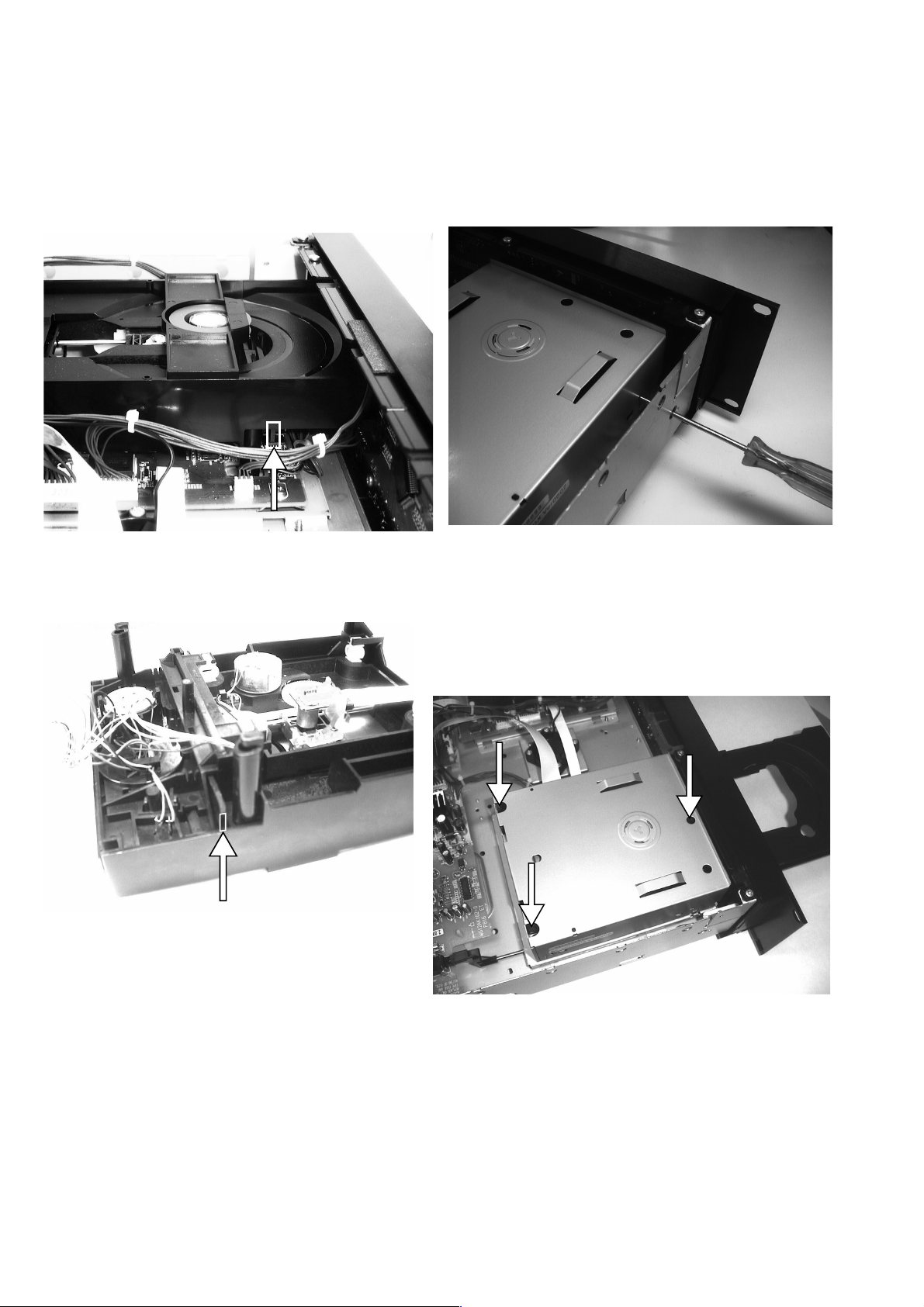
6. SERVICE PROCEDURE
• Emergency Eject (CD)
• Emergency Eject (CD-R)
1. To open the stucked tray, push the eject lever.
2. Use a pin ø4mm or less.
This picture shows the unit upside down. The eject lever is
pointed by the arrow.
The lever is thin so aim the narrow area carefully.
1. To open the tray when it is stuck, insert a pin into the
eject pinhole and push.
2. Use a pin ø4mm or less.
• Replacing the Mechanism Assy (CD-R)
1. Open the tray fi rst.
2. Remove the 3 screws shown in the picture below.
3. Disconnect all the wires at the right side.
4. Replace the MECHANISM ASSY(001M).
12
Page 15
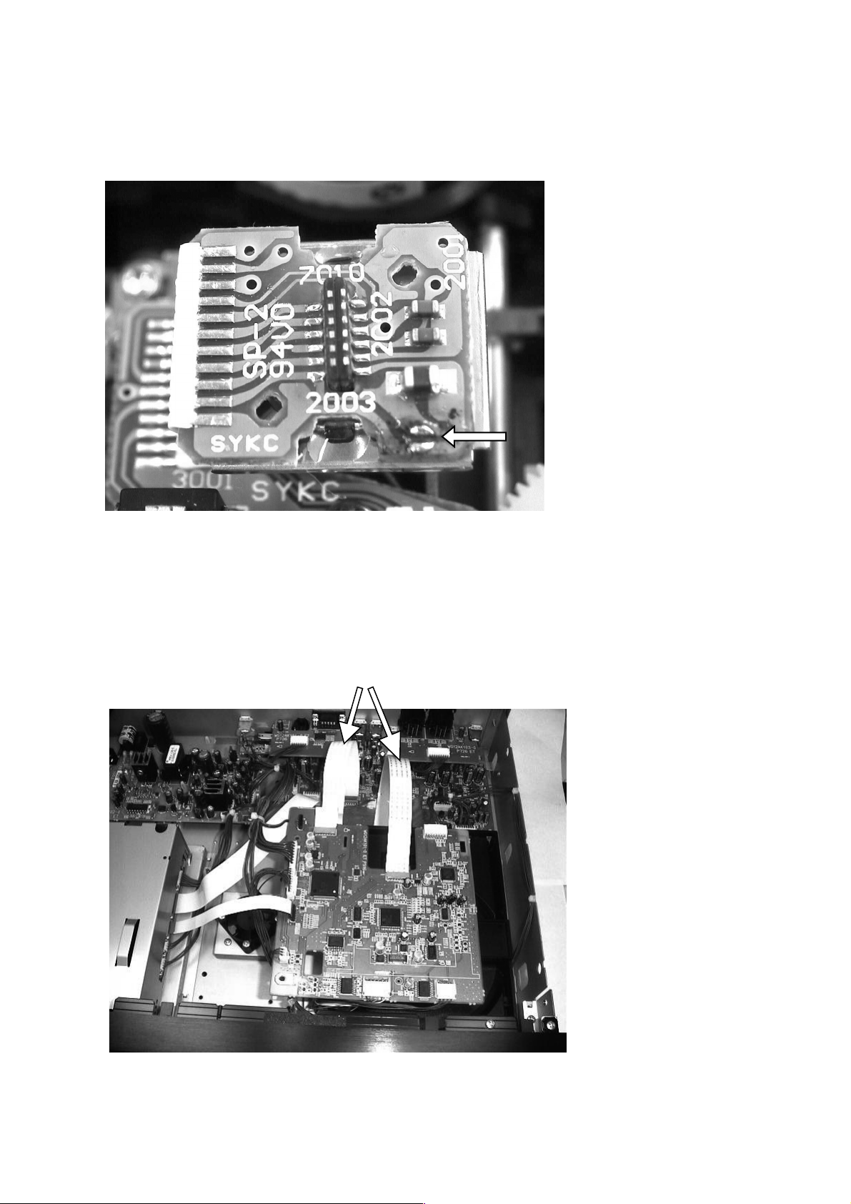
• Cautions in Assembling and Disassembling
When removing the fl at wire, connecting the optical pick up and the CD decorder board, short-cut the two lands pointed by
the arrow with solder. Otherwise the laser diode may be damaged by static electricity.
•
CD Decorder Board (PS01) Repair
When Repairing the CD decorder board PS16, you can fi x the board on the loader unit as shown in the pictuer below with
the fl at wires that are provided as service parts.
15P : YU15170010
13
Page 16

7. SERVICE MODE
1. Turning into Service Mode
While pressing STOP(CDR) and PLAY/PAUSE(CDR)
buttons, press POWER button.
Mode0,1,2 and 3 are CD Player side.
2. Mode 0 (display "VER_ *-** P00" )
Version number of The micro computer(QU01) is
displayed (*-**).
Status: [FOCUS OFF], [SPINDLE OFF], [RADIAL OFF],
[MUTE ON].
• While pressing
toward the outer edge. Release the button makes the
sledge return to the origin.
Tur n REC LEVEL/SELECT button clockwise to go to
Mode 1.
3. Mode 1 (display "VER_ *-** P01")
Status: [FOCUS ON], [SPINDLE OFF], [RADIAL OFF],
[MUTE ON]
Tur n REC LEVEL/SELECT button clockwise to go to
Mode 2.
4. Mode 2 (display "VER_ *-** P02")
Status: [FOCUS ON], [SPINDLE ON], [RADIAL OFF],
[MUTE ON]
Tur n REC LEVEL/SELECT button clockwise to go to
Mode 3.
5. Mode 3 (display "VER_ *-** P03")
Status: [FOCUS ON], [SPINDLE ON], [RADIAL ON],
[MUTE OFF]
When REC LEVEL/SELECT button is turned
counterclockwise, Mode is returned to Mode 2, Mode 1,
Mode0.
or button, the sledge moves
* In this Service Mode, all of the following button functions
work in any status.
1) Press TEXT button to light up all the FL segments.
2) Press STOP button(CD).Then press a button on the unit.
The name of the button is displayed.
Pressing a button on the remote displays the RC-5 code
of the button.
3) Press PLAY button in the Mode1, 2 or 3 then normal
operation can be performed. If an error occurs the error
number is displayed. (EX : Err 10) See the table below.
4) Terminating Service Mode
Turn off power to quit Service Mode.
Error Code Error
Err 02 FOCUS Error
Err 07 SUB CODE Error
Err 08 T. O. C. Error
Err 09 DECODER Error
Err 10 RADIAL Error
Err 11, 12 SLEDGE Error
Err 13 SPINDLE Error
Err 16 ~ 20 SEARCH Error
Err 30 DOOR Error
Err 31 TRAY Error
Err 32 ~ 47 BUTTON INPUT Error
14
Page 17

8. WIRING DIAGRAM
MAINS
RY06
QY41
DY01
PY16
WG388K201-0
001M
LOADER ASSY
JY03
QY04
CY14
TO TRAVERSE
FAN
SY04
CDR OPEN/CLOSE CD OPEN/CLOSECDR SELECT CD SELECTDJ MODE
QY02
QY03
RY11
RY26
SY07
SY05 SY22
ERASE
REC TYPE TEXT
SY06
SY08
FINALIZE
INPUT
SY09
RY02
RY01
RY03
LY01
CY06
CY10
RY25
RY24
RY23
RY22
RY21
RY13
RY12
CY13
CY09
SY26
MENU
SY23
CANCEL/DELETE BWD
SY16
SY15
QY01
SY12
SY13 SY10
TIME
SY17
SY21
RY35
RY34
RY33
RY32
RY31
CY08
RY17
RY16
RY15
CY03
PROGRAM
XY01
SY18
FWD
DY42
DY41
QY43
QY42
RY41
CY41
VY01
RY14
DY04
RY09
RY10
CY05
CY04
RY44
QY44
WY01
WY02
CY11
WY06
TO TRAVERSE TO TRAVERSE
15 16
Page 18

9. BLOCK DIAGRAM
VAL2212
LOADER
VAM2202/04
CDM
INSW
SL+FOC+RAD+-
DM+-
TRAY+-
TDA7073AT
x3
Moter Driver
LD
MON
CMFB
TRAY_CONT1,TRAY_CONT2
TZA1024T
RF AMP
D2..D4
D1..D5
LOAD_SW
AT24C04
EEPROM
SLEDGE
FOCUS
RADIAL
MOTO1
TRAY_CONT1
TRAY_CONT2
LASER
CDRW
EQSEL
HFI
VRIN
HFD
HFD
8.467MHz
SAA7324H/MB2
CD DECODER
CD_SDAO
CD_SCL
CD_RAB
CD_SILD
MAIN Microprocessor (NEW)
CD_SDAI
CD_RST
MB90F574
LP (RP)
LN (RN)
RCK
SUB
SBSY
SFSY
X16
EBU_OUT_CD
8.0MHz
CD PCB
NJM2904M
LPF
LC89170M
CD-TEXT
DECODER
TXT_REQ
TXT_SDA
TXT_SCL
L(R)_OUT_CD
SUPPLY PCB
POWER SUPPLY
HEAD PHONE PCB
HP_SEL
LINE_SEL
MUTE_HP
MUTE_LINE
+8.0VA
+5.0VA
+5.0VM
SWITCHING
+9.0VA
-9.0VA
-34V
DC+4.1V
MUTE
MUTE
MUTE
MAINS
H.P. OUT
ANA.
UNBALANCE OUT
(CD)
ANA.
UNBALANCE OUT
(CDR/CD)
INPUT SELECT
SW
BAL./UNBAL.
DISPLAY PCB
DISPLAY Microprocessor (same as CDR500)
FL
Display
8.0MHz
TMP87CH74F
KEY
Matrix
JOG
VOL_REQ, VOL_SDA, VOL_SCL
IIC_SDA, IIC_SCL
DIS_RSTN
IR
Receiver
CDR_RREQ
IR_OUT
RC_5
CDR_SREQN
CDR_SRDYN
CRD-RA2
CRD-RA2
CD-R/RW MODULE
CD-R/RW MODULE
CDR_SCL
CDR_SDAI
CDR_RSTN
CDR_SDAO
L(R)_OUT_CDR
EBU_COAX_IN
EBU_OPT_IN
EBU_CD_OUT
EBU_CDR_OUT
L(R)_IN_CDR
TC9413
Digital
Volume
INPUT SENS.VOL.
0dBu .. +22dBu
SW
for only
Japan
ANA.
UNBALANCE IN
ANALOG
BALANCE IN
DIG. OPTICAL OUT
(CD)
DIG. OPTICAL OUT
(CDR/CD)
DIGI.COAXIAL IN
DIGI. OPTICAL IN
DIG. COAXIAL OUT
(CD)
DIG. COAXIAL OUT
(CDR/CD)
DIG. COAXIAL OUT
(Loop through)
RC5 IN
RC5 OUT
I/O PCB
INT/EXT (RC5 )
1817
Page 19

10. SCHEMATIC DIAGRAM
C815
10n
J802
J801
T2A 250V
J820 J821F001
1
S801
2
1
12
AC IN
C854
100n
R851
560
L856 6.8uH
GND
GND
C868
100
25V
GND
4.7uH
C872
220
16V
L876
4.7uH
1
3
GND
Q851
LM317F
23
1
R853
10E
R852
220
L882
C858
FERRITE
100
10V
34
E
C863
10/50V
Q862
2SA1576
R864
10k
Q866
NJM7808
2
R856
1K
GND GND
Q871
L871
NJM78L12
1
GND
Q876
NJM79L12
3
GND
R892
22K
R891
22k
2
C855
10
50V
R861
10k
B
1
3E
GND
C
31
32
C873
100
16V
21
R893
10k
C891
100
25V
GND
2
GND
GND
C842
100n
Q861
1
2SC4081
C
B
2
L884
FERRITE
C870
10
50V
GND
C878
100
25V
L880
FERRITE
R894
1K
Q892
PC123F
1
2
L881
FERRITE
R862
22k
R863
10k
GND
L885
FERRITE
C875
100n
L886
FERRITE
GND
GND
GND
C844
100n
GND
C880
100n
C841
100n
D862
24V
C840
100n
4
C892
100
25V
3
GND
C864
10
50V
R854
FERRITE
L883
GND
470
GND
GND
100n
C843
GND
GND
GND
GND
GND
GND
GND
GND
GND
J851
J852
PH
J853
J829
EH
1
VDC2
2
VFTD
3
VDC1
4
MGND
5
+5VM
6
GND
7
GND
8
+5VA
1
+5VU
2
UGND
3
+5V
4
GND
5
+8VM
6
MGND
EH
1
+5VD
2
GND
3
+12MUTE
4
+12VA
5
GNDA
6
GNDA
7
-12VA
EARTH
D851
L851
AG01
4.7uH
R819
F:330K
U:2.2M
C820
N:1M
220n
1W
250v
43
21
L820
22mH
2
W801
EARTH
J828
EARTH
C819
100n
250V
C825
470p
400V
C826
470p
400V
C801
82P
R801 82k
GP
C802
820p
D802
S1WB(A)60
C828
470p
400V
GP
C829
4.7
50V
GP GP
GP GP GP
C809 1n5
GP GP GP GP
R823
R822
D829
24V
R809 330
18K
18K
1W
1W
C810
2.2
50V
R816 180
2
1
D803
AG01
D804
AG01
R829
10K
D814
AG01
R815 1.8k
C803
470p
43
GP
C821
120/400v
GP
C833
100
25V
GP GP
R814 1.8K
C834
22
50V
C814
100n
Q810
MC44603P
R803
4.7k
R808
GP
18k
D806
AG01
D807
AG01
R813
15E 1/6W
C813
2n2
R807
C804
4n7
R804
15k
P816
R825
1k
1/6W
GP
R826
1/6W
R811
22
1/6W
GPGP
180k
12345678
161514131211109
R802
22k
Q825
2SK2943
1G
1E
GP
C811
100n
GP GP
L825
FERRITE
2S
3D
R827
1E5
1/6W
D832
AG01
R810
10k
L832
10uH
R828
1E5
1/6W
R805
15k
L831
1
2
3
C827
470pF
4
1kV
5
67
GP
R812
100
Q801
PC123F
4
3
GP
R806
1K
1
2
GND
C881
100
16V
Q881
TL431
R882
100
2
1
GND
14
13
12
11
10
9
8
C882
0.022
3
GND
C851
100n
D856
RK46
D861
AG01
D866
RU4AM
C866
100n
D876
AG01
R883
R884
C856
100n
GND GND
C861
100n
GND
GNDGND
D871
AG01
C871
100n
1.8k
2.2K
1%
R885
820
C852
330
16V
C853
100
16V
L852
4.7uH
C862
10/50V
GND
6.8uH
C867
1000
16V
C876
100n
GND GND
R887
100
R881
3.3k
GND
C857
2200
16V
L861
4.7uH
L866
GNDGND
C877
220
16V
Q891
2SC4213
"NOTE ON SAFETY: The parts marked with are IMPORTANT PARTS on the safety.
Please use the parts having the designated parts number without fail"
19 20
Page 20

1234567
GND
GND
C112 R133
100n 22R
4.8V
1.7V
1.7V
+5VM
R122
12k
Radial
2.6V
5V
0.8V
0.2V
0.7V
0V
3.8V
Part of RF AMP
Q101
TZA1024T/N1
0V
4.8V
0V
0V
1.9V
0.8V
1.8V
C102
10n
R104
220k
0.2V
0V
C118R130
22R
100n
4.8V
4.6V
9.8V
R116
MGND
R115
12k
R119
15k
1k
C121
1n
FOCUS
C120
100n
R110
47R
GND
148 9 10 11 12 13
EJ
47/6.3V
GND
C101
5p
4.7K
R101
C105
47/6.3V
EJ
R105
2.2K
GND
Part of Loader Cont.
C113
100n
MGND
+REF
1.7V
5V
1.7V
C116
1n
+5VA
R103
R102
4.7K
4.7K
R149
150k
+5VA
R150
10k
C132
100n
1.8V
R148
100k
1.2V
GND
R142
2.2K
GND
16 15 14 13 12 11 10 9
4.9V
Q104
TDA7073AT
9.8V0V0V
12345678
MGND
+5VM
C119
100n
C109
47/16V
MGND
TRAY_CONT1
Laser H: Laser on
RW H: CD-RW Play
5V
R147
2.2K
Q112
2SC4081
R146
2.2K
1.2V
R144
1k
R125
390E
C127
100n
R123
12k
D101
1SS301
3.8V
Q111
2SC4081
0.6V
GND
C130
100n
4.8V
R220
12k
TRAY_CONT2
PS16
C129
1n
R141
470R
C133
100n
GND
+REF
2
31
4.6V
C131
1n
GND
R137
100k
R143
100k
GND
4
GND
OP-AMP1/2
1
Q115
NJM2904
Q115
NJM2904
OP-AMP2/2
7
8
0.6V
R138
100k
4.8V
+VR
B
1.9V
R139
2
1k
2
3
E
C
GND
0V
GND
C110
100/16
6
5
R145
100R
3
Q110
1
R140
10k
Q109
2SC4081
GND
2SA1576
+5VA
R131
2.2K
EQSEL
RW
VRin
2
GND
31
D102
1SS301
+VR
R132
2.2K
Laser
HFI
D2
D1
D4
D3
D5
HFD
Radial
FOCUS
Sledge
MOTO1
MOT_SW
RW
INSW
Laser
EQSEL
HFI
VRin
D2
D3
D4
D5
D1
HFD
LOAD_SW
TRAY_CONT2
TRAY_CONT1
Radial
FOCUS
Sledge
MOTO1
MOT_SW
RW
INSW
Laser
EQSEL
HFI
VRin
D2
D3
D4
D5
D1
HFD
LOAD_SW
TRAY_CONT2
TRAY_CONT1
R211
68R
TP205
TP204
TP211
6
5
4
3
2
1
GND
GND
TP212
GND
TP226
+5VD
R109
10k
R108
DM
Q107
DTC114EU
Q108
DTC114EU
RAD-
FOC+
FOC-
RAD+
+5VA
C108
47/6.3V
EJ
SL-
SL+
DM+
DM-
INSW
TP229
LOAD_SW
TRAY-
TRAY+
2
MOT_SW
2
TP206
TRAY+
TRAY-
FOC+
FOC-
RAD-
RAD+
SL+
SL-
DM+
DM-
TP230
C128
100n
C124
100n
R129
1k
R136
180k
+REF
TP224
TP231
TP214
MGND
R135
3.3K
R127
15k
TP207
TP217
J101
FPC15
1
TRACKING
2
3
FOCUS
4
5
6
D2
7
D1
8
D4
MD
LD
SHORT
LAND
1/2VCC
9
10
11
12
VCC
13
D5
14
D3
15
M
SPINDLE MOTOR
M
SLED MOTOR
LIMIT SWITCH
J104
XH6P
J102
HX4P
TRAY SWITCH
M
TRAY MOTOR
4
3
2
1
+5VA
3
1
Q106
DTA114EU
2
1
3
GND
1
+5VA
TP215
TP216
TP208
TP232
TP225
TP233
R126C117
R134C114
22R100n
16 15 14 13 12 11 10 9
5.2V
1.7V
12345678
4.5V
C125
100n
4.8V
9.8V
Q103 Q105
TDA7073AT TDA7073AT
1.7V
+5VM
MGND
R182
220K
MOTO1
Q113
2SC4081
22R
100n
R121
10k
R212 R213
5R6 5R6
GND
2.7K
5.6K
R113
R111
Part of Servo Driver
4.9V
1.7V
1.7V
Sledge
R124
R120
12k
+REF
1k
C122
100n
C123
100n
MGND MGND
Q114
2SC4081
C106 C107
47/6.3V
EJ
C104
4n7
R107
15k
C103
100n
5.6K
R114
R106
100k
Q102
2SC4081
Output from Photo Diode
16 15 14 13 12 11 10 9
MGND
C111
100n
+REF
12345678
R117
1.5K
C126
1n
C115
1n
R118
18k
3
+REF
+REF
1
3
DM
Q120
MOT_SW
2
1
3
2
Q119
DTC114EU
GND
10K
R183
1
3
GND
Q118
DTC114EU
3
2
1
Q117
DTA114EU
2
2221
Page 21

+5VA
GND
GND
+5VM
MGND
VDC1
VFTD
VDC2
FOCUS
1.9V
1.7V
CL16
26
L150
FERRITE
C159
22p
10LD9
F-R
C183
10n
R207
220
N.C9VCC
6Y7
Radial
R194
10R
1.8V
1.7V
DATA
54RA55FO56SL57
27
8CK7CE6
8
+3.3VD
CFLG
1.7V
WCLK
GND
DA
Z
GND
53
28
R175
100R
51
52
DOBM
VDDD1
1.7V
3.4V
4.5V
0.1V
4.4V
4.2V
4.8V
1.7V0V0V
SCLK
30EF29
C184
22P
GND
Q152
74LS628
Radial
FOCUS
Sledge
MOTO1
RW
RW
INSW
Laser
HFI
VRin
D2
D3
D4
D5
D1
J181
8
GND
7
GND
6
5
MGND
4
3
2
1
+5VA
+5VA
Radial
FOCUS
Sledge
MOTO1
RW
RW
INSW
Laser
HFI
HFI
VRin
D2
D3
VRin
D4
D5
D1
D2
D3
D4
D5
D1
+5VA
+5VM
VDC1
VFTD
VDC2
C137
100n
5.0V
PS16
L101
FERRITE
R181
Q116
NJM2391DL1-33
GND
2
GND GND
GND
+3.3VA
330p
C166
GNDGNDGND
47/6.3V
180p
C167
47/6.3V
C140
L102
FERRITE
GND
C150
180p
C170
C136
EJ
EJ
GND
R156
10k
R158
10k
10k
R159
10k
R161
R164
10k
C163
180p
GND
C135C134
100n100n
47E
GND
31
OUTIN
C138 C139
47/6.3V 100/16V
EJ
C151 R174
1n 1k
R166
R151
470R
47n
R155
R157
R160
R162
R163
R165
180p
C173
+3.3VA
+3.3VD
10k
10k
10k
10k
10k
10k
+5VD
+5VPLL
47R
R152
220p
GND
0.8Vp-p
1M
C164
220p
C165
+3.3VA
C162
47/6.3V
220p
C168
+5VPLL
C155
EJ
GND
220p
C169
22n
R153
100n
GND
C152
10n
220p
C171
C179
22k
220p
C174
GND
8.4672MHz
GND
R167
C178
47/6.3V
X151
C176
22P
C154
47P
R154
1k
1
2
3
4
5
6
33k
7
8
9
10
11
12
13
14
15
16
GND
R179
4R7
12
43
GND GND
+5VPLL
C185
100n
R201
1M
GND
HFREF
HFIN
ISLICE
VSSA1
VDDA1
IREF
VRIN
D1
D2
D3
D4
R1
R2
VSSA2
CROUT
CRIN
R169R168
22R22R
C188
47/6.3V
Laser
3.4V
LDON
1.4V
1.6V
1.6V
0V
3.3V
1.2V
1.8V
1.8V
1.8V
1.8V
1.8V
1.8V
1.8V
0V
1.7V
1.3V
3.4V
VDDA2
C186
1n5
C160
100/16V
EJ
R202
100
C177
22P
EJ
100/16V
INSW
3.4V
C181
DM
C182
GND
0V
GND
RW
19LP18LN17
GND
GND
C175
1u
61V462V563V164
0V
0V
VNEG
20
GND
16
1
C189
XOUT
XIN
100n
C153
MOTO1
1u
58
59
60
VDDD2
MOT01
MOT02
VSSD 3
3.4V
1.9V
Q150
SAA7324H/M2B
3.4V
VPOS
15
14
3.4V
SELPLL
23RP22RN21
C191
1n5
C187
100n
Q151
BU2630FV
VDD14TPD13P-T12TON11F-T
P-R3RPD
VSS
4
2
R203
GND
10K
R204
0
R205
13FC12RX11RX10
OSC_VCC
OSC_GND2RNG3CX14CX25EN
1
24
GND
5
R200
22
680
Sledge
1.7V
0V
TEST1
25
RON
C193
1u
GND
VSSD2
0V
0.8V
0V
TEST2
50
CL11/4
TEST3
STATUS
SILD
RESET
SCLI
WCLI
V2/V3
VSSD1
KILL
31
GND
49
0.1V
SBSY
2.6V
SFSY
RAB
SCL
SDA
SDI
0V
32
J150
0V
SUB
RCK
R195
10R
GND
48
47
46
45
44
43
42
41
40
39
38
37
36
35
34
33
GND
GND
R171
+3.3VD
+VR
C158
22P
GND
R172
1k
2.2k
C192
100n
GND
+5VD
TC74HCT08FA
Q252
L151
FERRITE
R199
220R
SBSY
SFSY
SUB
RCK
RCK
SUB
SBSY
SFSY
1k
R251
R252
2.2k
C253
100n
GND
C251
GND
GND
+5VA
14 13 12 11 10 9 8
1234567
100n
GND
R256
1234567
22K
GND
0.8V
0V
0V
2V
1.7V
4V
0V
10k
R189
10k
R190
GND
+5VD
10k
10k
DM
R192
R191
R193
100
R208
R209
100
R210
100
R206
100
Part of CD TEXT
Q251
LC89170M
141312111098
3.4V
3.3V
0V
4.2V
3.4V
0V
0V
R257
100
GND
R253
2.2K
C252
100n
GND
C254
22P
GND
GND
R254
2.2K
R255
1K
EMPH
CD_SILD
CD_RAB
CD_SCL
CD_SDAIO
CD_RST
PLL_CS
SCLK
DATA
WCLK
PLL_CL16
TXT_SCL
+3.3VD
EBU_OUT_CD
TXT_REQ
TXT_SDA
22P
C190
GND
23 24
Page 22

MP_RQST
MP_STB
EE_SCL
EE_SDA
WCLK
SCLK
DATA
PLL_CL16
MP_RST
+2.7V
+2.7V
RM16
1k
RM03
10R
RM15
10R
100n
GND
100n
CM05
GND
100n
CM03
GND
CM04
GND
GND
1
2
3
4
5
6
7
8
9
10
11
12
13
14
15
16
CD_LRCK
CD_BCK
CD_SDI
DREQ
VDD_1
VSS_1
BS_LRCK
BS_BCK
BS_SDI
VDD_2
VSS_2
LRCK1
BCKI
SDI
RESET
TESTEN
RM18
470k
SDA
XTI
10R
+2.7V
RM14
CM06
100n
+3.3VD
54
55
GPSO_CK
GPSO_SDO
IODAT1
IODATA0
27
26
RM06
CM16
53
VSS_7
VDD_5
VDD_3
IODAT2
28
10R
100n
52
IODATA15
VSS_4
29
100n
CM08
50
51
IODATA12
IODATA14
IODATA11
IODATA10
IODATA9
IODATA8
PLL_GND
PLL_VCC
IODATA7
IODATA6
IODATA3
31
30
49
IODATA13
VSS_6
VCC_2
FILT0
FILT1
VSS_5
VDD_4
IODATA4
32
+2.7V
GND
48
47
46
45
44
43
42
41
40
39
38
37
36
35
34
33
IODATA5
GND
CM15
100n
RM05
CM11
GND
100n
CM10
GND
GND
10R
RM02
RM07
10R
100n
TP219
+3.3VD
10R
+3.3VD
+2.7V
TP221
CM14
CM13
CM23
470P
4n7
RM04
RM20CM24
1K4700P
TP223
4R7
470p
RM01
1k
RM08
10R
CM09
100n
56
57
58
59
60
61
62
63
64
SCL
VDD_6
VSS_9
STB
RQST
VCC_3
VSS_8
GPSO_REQ
QM01
STA016T
CLKOUT
VSS_3
VCC_1
SDO
BCKO
LRCKO
OSCK
XTO
22
21
20
19
18
17
23
100n
CM07
25
24
PS16
100
100
FERRITE
RM11
RM10
RM12
100
RM13
GND GND
RM09
10R
+3.3VD
CM17 CM18 CM19 CM20
22P 22P 22P 22P
GND
+3.3VD
+2.7V
RM17
10R
RM19
2SC4672
1
C
470R
QM02
B
LM01
LM02
LM03
LM04
2
3
E
FERRITE
FERRITE
FERRITE
FERRITE
EMPH
DAC_RES
CD_DMUTE
CM02
100/16V
GND
FAN
+2.7V
TP220
TP222
JM01
1
SDA
2
SCK
3
LRCK
4
MCLK
5
EMPH
6
DAC_RES
7
FAN
8
CD_DMUTE
2625
Page 23

MP3_LED
+5VD
GND
N.C
FL_SCL
GND
FL_SDA
VDC1
VFTD
VDC2
JU04
GND
JU03
TP235
TP237
TP239
TP241
TP243
+5VD
TP236
TP238
TP240
TP242
RU21
100
RU22
RU10
RU16
RU17
RU13
RU14
TP246
100
100
100
100
100
100
CD_RST
CD_SILD
MP_RQST
LOAD_SW
TRAY_CONT1
TRAY_CONT2
MOT_SW
CD_SDAIO
CD_SCL
CD_SILD
CD_RAB
CD_SILD
HFD
TXT_SDA
TXT_SCL
TXT_REQ
CD_DMUTE
EE_SDA
EE_SCL
MP_STB
MP_RST
PLL_CS
DAC_RES
EQSEL
GND
JU01
GND
FAN
JU02
1
GND
2
HP_SEL
3
LINE_SEL
4
HP_MUTE
5
CDR_MUTE
6
VOL_SDA
7
VOL_SCL
8
VOL_CS
9
CD_MUTE
10
EBU_OUT_CD
11
CST
12
RST
13
TXD
14
RXD
15
MP3_SEL
1
N.C
2
GND
3
CDR_RRSTN
4
CDR_SDAI
5
CDR_SDAO
6
CDR_SCL
7
CDR_RREQ
8
CDR_SRDYN
9
CDR_SREQN
TP244TP245
3
RU19
4.7K
TP265
GND
1.5K
1.5K
1.5K
1.5K
+5VD
+5VA
TP266
1
RU20
47K
VDC1
VFTD
VDC2
TP268
GND
8765
VCCWPSCL
QU11
AT24C04
EEPROM
GND
RU06
1
RU07
2
RU08
3
RU09
TP203
10
9
8
7
6
5
4
GND
FL_SCL
GND
FL_SDA
FL_RSTN
3
2
1
TP250
TP249
TP251
+5VD
100n
A0A1A2
1234
GND GND GND
+5VD +5VD+5VD +5VD
JU99
9+5VD
8TAUX3
RU01
+5VD
7TMODE
6TRESN
5TCK
4TRXD
3TTXD
2TAUX
1GND
TCK
TRXD
TTXD
TAUX
GND
DTA114EU
1
10k
RU02
2
+5VD
QU04
3
2
RU11
4.7k
RU12
4.7k
SDA
GND
10k
10k
47k
RU04
RU03
+5VD
54
QU02
BD4719G-TR
123
GND GND
+5VD
CDR_RSTN
CDR_SREQN
CDR_SRDYN
CU07
100n
GND GND
CD_MUTE
GND
CD_DMUTE
FL_RSTN
FL_SDA
FL_SCL
CDR_RREQ
TXT_REQ
HFD
MP_RQST
CDR_MUTE
RU05
10k
HP_SEL
GND
CU05
LINE_SEL
HP_MUTE
HP_SEL
VOL_CS
VOL_SCL
VOL_SDA
100n
+5VD
47
48
49
50
51
52
53
54
55
56
57
58
59
60
P81
P82
P83
P84
P85
P86
P87
VCC
P90
P91
P92
P93
P94
P95
P96
61
P97
62
VSS
63
PA0
64
PA1
65
PA2
66
PA3
67
PA4
68
PA5
69
PA6
70
PA7
71
PB0
72
X1A
73
X0A
74
PB1
75
PB2
76
PB3
77
PB4
78
PB5
79
PB6
80
PB7
81
PC0
82
PC1
83
PC2
84
PC3
85
HSTX
86
MD2
87
MD1
88
MDO
89
RSTX
90
XI
XO
VSS
92
91
PO0
VCC
95
94
93
GND
XU01
8.0MHz
1
2
3
+5VD
GND
96
PO1
CU06
100n
PO2
97
RU18
22K
PO3
98
PO6
PO5
PO4
99
101
100
+5VD
102
PO7
P10
103
QU01CU11
MB90F574
P11
104
CU04
100n
+5VD
GND
GND GND
43
44
45
46
P80
AVRL
AVSS
P14
P13
P12
108
107
106
105
GND
42
AVHR
P15
109
AVCC
P16
110
41
P74
P17
EQSEL
CU03
100n
40
P73
P20
111
GND
39
112
DVSS
P21
38
DVCC
P22
113
PLL_CS
CD_SILD
37
P72
P23
114
36
P71
P24
115
CD_RAB
GND
34
35
P70
P25
117
116
CU02
100n
GND
C
P26
33
VSS
P27
118
MP_STB
32
119
GND
MP_RST
31
P67
VSS
120
P66
P30
P65
P64
P63
P62
P61
P60
P57
P56
P55
P54
P53
P52
P51
P50
P47
P46
P45
P44
P43
P42
P41
P40
VCC
P37
P36
P35
P34
P33
P32
P31
30
29
28
27
26
25
24
23
22
21
20
19
18
17
16
15
14
13
12
11
10
9
8
DAC_RES
7
6
MP3_SEL
5
MOT_SW
4
TRAY_CONT2
3
TRAY_CONT1
2
LOAD_SW
1
EE_SDA
EE_SCL
CD_RST
CD_SCL
CD_SDAIO
TXT_SCL
TXT_SDA
CDR_SCL
CDR_SDAO
CDR_SDAI
CST
RST
TXD
RXD
TCK
TRXD
TTXD
FAN
CU01
100n
GND
LINE_SEL
HP_MUTE
CDR_MUTE
VOL_SDA
VOL_SCL
VOL_CS
CD_MUTE
CST
RST
TXD
RXD
MP3_SEL
CDR_RSTN
CDR_SDAI
CDR_SDAO
CDR_SCL
CDR_RREQ
CDR_SRDYN
CDR_SREQN
+5VD
EBU_OUT_CD
TP247
TP248
CU15
47P
GND
CD_RST
CD_SILD
MP_RQST
LOAD_SW
TRAY_CONT1
TRAY_CONT2
MOT_SW
CD_SDAIO
CD_SCL
CD_SILD
CD_RAB
CD_SILD
HFD
TXT_SDA
TXT_SCL
TXT_REQ
CD_DMUTE
EE_SDA
EE_SCL
MP_STB
MP_RST
PLL_CS
DAC_RES
EQSEL
FAN
CU08
47P
CU09
47P
CU10
47P
CU12
47P
CU13
47P
CU14
47P
DTA114EU
QU03
GND
TAUX
PS16
27 28
Page 24

BALANCE IN
L ch
BALANCE IN
R ch
OPTICAL OUT
CD
Only for Japan
L_HOT
L_COLD
A-GND
A-GND
R_HOT
R_COLD
+5VD
GND
OPT_OUT_CD
UNBALANCE IN
L ch
R ch
J701 L701
XLR
1
2
12
3
3
G
4
J702
XLR
1
2
12
3
3
G
4
J392
1
2
3
C715
47/25V
WA04
C717
1
47
25V
2
3
GNDGND
OPT_OUT_CD
J751
1
3
GND
2
GND
C718
C751
47p
C752
47p
C716
47
25V
4
5
6
7
8
9
GND
GND
R715
33k
R719
R717
33k
R716
R720
+5VD
1k
R722
50kC
47/25V
R718
33k
GND
GND
C703
47p
GND
GND
1k
R721
50kC
2
R723
470
33k
2
R724
470
GND
GND
GND
C701
47p
GND
C702
47p
GND
C704
47p
C392
10
50V
3
1
3
1
L751
FERRITE
L752
FERRITE
FERRITE
C705
L703
FERRITE
C707
L702
FERRITE
C706
L704
FERRITE
C708
R729
100
R725
100k
R737
4.7k
GND
R739
2.2k
R727
100k
R731
100
R730
100
R726
100k
R738
4.7k
GND
R740
2.2k
R728
100k
R732
100
C753
47/25V
C754
47/25V
47p
47p
47p
47p
GND
GND
GND
GND
R701
100k
GND
GND
GND
GND
5
OP-AMP1/2
6
R733
4.7k
C719
47p
C721
47p
2
OP-AMP2/2
3
5
6
C720
47p
C722
47p
R736
4.7k
2
OP-AMP2/2
3
R703
100k
R702
100k
R704
100k
Q701
NJM4558M
8
+12VA
R735
4.7k
NJM4558M
4
8
OP-AMP1/2
R734
4.7k
4
NJM4558M
R751
100k
GND
R752
100k
GND
C709
47p
C710
47p
7
C728
220
16V
GND
1
Q701
Q702
NJM4558M
7
1
Q702
R741
4.7k
C723
47p
R742
4.7k
C724
47p
GND
R744
4.7k
R743
4.7k
-12VA
+12VA
-12VA
C727
220
16V
R745
4.7k
P726
GNDGND
R746
4.7k
GNDGND
GND
GND
4
3
OP-AMP1/2
2
R747
4.7k
C725
47p
-12VA
4
3
OP-AMP1/2
2
R748
4.7k
P716
J705 JR02
1
L_HOT
2
L_COLD
3
-12VA
Q703
NJM4558M
1
NJM4558M
Q704
1
C726
47p
A-GND
4
A-GND
5
R_HOT
6
R_COLD
7
+5VD
8
GND
9
OPT_OUT_CD
NJM4558M
Q703
6
OP-AMP2/2
R753
5
4.7k
C756
47p
6
OP-AMP2/2 OP-AMP1/2
R754
5
4.7k
+9VA
R765
100k
S751
123
OPT_OUT_CDR
C755
47p
R755
4.7k
7
8
+12VA
+9VA
16
15X214X113X12X011X310A9
VDD
Q707
BU4052
Y02Y2
1
3Y4Y35Y16
GND
R756
4.7k
7
Q704 Q706
8
NJM4558M NJM2082M
+12VA
GND
654
+5VD
R761
15k
GND
CTS
RTS
TXD
RXD
GND
GND
GND
7
6
5
4
3
2
1
R757
4.7k
INH7VEE
GND
-9VA
R762
15k
GND
2
OP-AMP1/2
3
B
VSS
8
R758
4.7K
1
3
GND
+5VD
GND
-12VA
2
3
C757
47p
R759
4.7k
4
NJM2082M
4
CR03
100n
CR04
100n
GND
1
Q705
L_BUFF_CD
R_BUFF_CD
C758
47p
R760
4.7k
-12VA
Q709
DTC114EU
2
CR05
100n
P736
JR03
1
1
C1+
2
V+
3
C1-
4
C2+
5
C2-
6
V-
7
T2OUT
8
R2IN
C771
47/25V
47/25V
CR02
QR01
HIN202E
TXD
RXD
1
TXD
RXD
C772
100n
2
GND
C776
220
16V
T1OUT
R1IN
R1OUT
T1IN
T2IN
R2OUT
RTS
3
RTS
R771
10k
C775
220
16V
GND
VCC
GND
16
15
14
13
12
11
10
9
OPT
CTS
5
4
GND
CTS
OPT_OUT_CDR
+12VA
GND
-12VA
GND
R772
10k
MP3_SEL
GND
+5VD
GND
+5VD
6
16
VDD15OUT
VSS2OUT
1
CR01
100n
GND
CR06 CR07
100P 100P
GND
7
R777
15k
GND
14IN13
Q708
TC9413AP
3IN4
R778
15k
GND
+5VD
+5VD
GND
R779
15k
GND
R773
4.7k
GND
GND
12
11
N.C
CS210STB
A-GMD
N.C
CS17GND
A-GND
5
6
GND GND
GND
R780
15k
GND
R774
4.7k
C391
10
50V
GND
OPTICAL OUT
CDR
Only for Japan
CR08 CR09
100P 100P
GND
GND
6
OP-AMP2/2
5
8
+12VA
9
DATA
CK
8
C774
47p
6
OP-AMP2/2
5
8
+12VA
GND
RXD
RTS
TXD
CTS
GND
GND
C773
47p
R775
3.3K
Q705
NJM2082M
R776
3.3K
Q706
NJM2082M
7
7
1
2
3
J391
OPTICAL OUT
12
67
3
8
45
9
R781
100
D773
4.7V
D771
4.7V
VOL_CS
VOL_SDA
VOL_SCL
R782
100
D772
4.7V
JR01
D-SUB FEMALE
GND
J771
PH
1
L_IN_CDR
2
GND
GNDGND
3
R_IN_CD R
4
GND
(to CRD-RA2)
D774
4.7V
GND
ANALOG INPUT Select
BALANCE / UNBALANCE
3029
Page 25

L_OUT_CDR
GND
R_OUT_CDR
(to CRD-DA2)
+5VD
GND
+12MUTE
+12VA
GND
GND
-12VA
GND
HP_SEL
LINE_SEL
HP_MUTE
CDR_MUTE
VOL_SDA
VOL_SCL
VOL_CS
CD_MUTE
EBU_OUT_CD
CTS
RTS
TXD
RXD
MP3_SEL
1
2
3
4
5
6
7
J631
L_BUFF_CD
J601
1
2
GND
3
J602
GNDGNDGND
C607
220
16V
1
2
3
4
5
6
7
8
9
10
11
12
13
14
15
+5VD
+12MUTE
GNDGND
GND
R601
100
R602
100
R616
680
R615
680
C608
220
16V
R605
4.7K
GND
R606
4.7K
GND
GND
C611
560P
GND
D632
8.2V
D633
C612
560P
8.2V
+12VA
-12VA
LINE_SEL
2
OP-AMP1/2
3
4
6
OP-AMP2/2
5
GNDGND
GND
GND
VOL_SDA
VOL_SCL
VOL_CS
EBU_OUT_CD
CTS
RTS
TXD
RXD
MP3_SEL
C601
330P
R603
3.9K
Q601
NJM4558M
-12VA
8
+12VA
C620
100/16V
C619
100/16V
1
C602
330P
R604
3.9K
Q601
NJM4558M
+9VA
-9VA
R611
10k
R607
10k
7
R608
10k
C605
47/25V
C603
GND
R_BUFF_CD
47/25V
C604
47/25V
R610
10k
DTC114EU
2
GNDGND
GND
GNDGND
Q631
R613
10k
R609
10k
C606
47/25V
+9VA
GND
1
3
GNDGND
R680
22K
R614R612
10k10k
DTC114EU
2
+9VA
16
15X214X113X12X011X310A9
VDD
Y0
+9VA
15X214X113X12X011X310A9
16
VDD
Y0
+9VA
R681
22K
Q632
1
3
GND
2
Q603
BU4052BCF
Q604
BU4052BCF
R675
4.7K
Q663
DTC114EU
5Y14Y33Y2Y21
C614
47/25V
5Y14Y33Y2Y21
GND
C613
47/25V
INH
6
INH
6
GND
+12MUTE
R676
100k
1
2SC4081
3
GND
7
-9VA
GND
7
-9VA
Q664
VEE
VEE
Q665
2SA1576
3
E
R678
4.7K
2
B
L-HP2GND3R-HP4+12VA5GND6-12VA7KILL_HP
1
L623
FERRITE
R617
47K
GND
B
VSS
8
GND
B
VSS
8
D631
1SS302
R679
100k
1
C
2
B
C
1
-12VA
E
3
GND
J605
C615
1000P
GND
L624
FERRITE
R618
47K
GND
13
2
R642
0E
E
3
C618
100n
1000P
GND
2
Q641
2SA1576
GND
GND
C616
GND
B
R643
100
C
1
E
3
C631
470
16V
L625
2
2SA1576
GND
L626
FERRITE
-12VA+12VA
R621
4.7K
R622
4K7
Q602
NJM4558M
B
C
1
Q633
FERRITE
2
OP-AMP1/2
3
6
OP-AMP2/2
5
2
E
3
C617
100n
GND
4
-12VA
8
+12VA
Q634
B
2SA1576
C
1
DTC114EU
2
CD_MUTE
C621
47p
R623
4.7K
Q602
NJM4558M
C622
47p
R624
4.7K
R650
2.2K
R644
4.7K
Q635
1
7
R626
10k
1
3
R625
10k
GND
R645
100k
R646
B
Q636
2SC4081
GND
4.7K
2
C624
47/25V
R628
10k
3
E
C
E
GNDGND
C623
47/25V
2
1
3
GND
B
R627
10k
1
C
-12VA
GND
Q637
2SA1576
R647
100k
P716
R629
100R
3
Q621
45
HN1C03F
GND
R633
4.7K
R635
4.7K
R630 R632
100R 100R
3
Q622
HN1C03F
42
R634
GND
4.7K
R636
4.7K
R648
4.7K
Q638
DTC114EU
2
1
3
GND GND
R631
100R
R649
100k
Q639
2SC4081
R640
4.7K
2
B
GND
GND
3
E
6
E
12
6
E
15
2
C
1
E
3
L621
FERRITE
C625
560P
L622
FERRITE
1
C
B
-12VA
GND
C626
560P
GND
Q640
2SA1576
R641
100k
GND
J621
1
3
2
CDR/CD OUT
L ch
R ch
31 32
Page 26

J651
SDA
SCK
LRCK
MCLK
EMPH
DAC_RES
FAN
CD_DMUTE
FAN
J655
1
2
3
4
5
6
7
8
1
2
GND
+5VD
+5VC
C682
100n
GND
CD_DMUTE
R685
22K
R686
22K
D650
GND
GND
C683
22P
+12VA
C684
1
74HCU04
1234567
22P
GND
Q656
IN OUT
CTL
+5VC
Q654
GND
GND
+12VA
+5VC
+5VC
C680
47/25V
14131211109
C685
GND
8
GND
+5VC
2
C650
34
47/25V
GND
100n
R687
22K
GND
GND
C681
100n
1
2
3
4
5
6
7
8
9
10
RST
VL
SDATA
SCK
LRCK
MCLK
M3
M2
M1
M0
Q655
78L05
1
GND
Q653
CS4392
32
C678
47/25V
GND
AMUTE
LOUT+
LOUT-
GND
RCH+
RCH-
BMUTE
CMOUT
FILT+
VA
GND
47/25V
C679
100n
C663
L_BUFF_CD
L651
FERRITE
C657
560P
6
42
GNDGND
FERRITE
6
42
GND
R_BUFF_CD
GND
GND
L652
GND
J661
1
3
2
C658
560P
CD OUT
L ch
R ch
R677
2.7K
C651
2
3
C675
2200P
2
3
C676
2200P
470P
OP-AMP1/2
4
-12VA
C652
470P
NJM4558M
OP-AMP1/2
4
-12VA
1
Q651
NJM4558M
Q652
1
GND
C662
220
16V
6
R659
4.7K
Q651
NJM4558M
6
R660
4.7K
Q652
NJM4558M
CD_MUTE
5
5
R655
R651
20
C671
47/25V
19
18
C673
17
47/25V
16
GND
C672
15
47/25V
C674
14
47/25V
13
12
GND
11
GND
GND
C664
47/25V
C677
100n
2.2K
R653
2.2K
R683
3.3K
R652
2.2K
C670
3300P
R654
2.2K
R684 C660
3.3K DM
2.2K
C669
3300P
R657
2.2K
C659
DM
GNDGND
GND
GND GND
R656
2.2K
R658
2.2K
GND
R682
2.7K
OP-AMP2/2
8
+12VA
OP-AMP2/2
8
+12VA
C653
47p
R661
4.7K
C654
47p
R662
4.7K
7
GND
7
R663 R665
10k 10k
GND
C661
220
16V
C656
47
25V
R664
10k
GND
C655
47
25V
GND
R668 R670
100R 100R
R666
10k
GND
R672
R667
100R
R671
4.7K
4.7K
R669
Q661
HN1C03F
3
15
R673
4.7K
Q662
HN1C03F
3
15
GND
R674
4.7K
100R
P716
W901
L_HP
GND
R_HP
+12VA
GND
-12VA
KILL_HP
R909
10k
L901
FERRITE
1
2
L902
GND
FERRITE
3
L903
4
FERRITE
5
GND
6
7
L904
FERRITE
C902 C901 C904 C903
2n2 2n2 47p 47p
+12VA
-12VA
6
45
GND
R903
10kB
3
12
GND
R903
10kB
R910
10k
GND
GND
R905
4.7K
R906
4.7K
6
5
2
3
C907
47p
R907
15k
OP-AMP2/2
NJM4556M
8
+12VA GND
C908
47p
R908
15k
OP-AMP1/2
NJM4556M
4
-12VA
7
Q901
1
Q901
C905
47/16V
EJ
C906
47/16V
EJ
GND
R902
47k
GND
R901
47k
R911
75E
Q903
HN1C03F
R915
4.7K
R917
4.7K
R912
75E
Q904
HN1C03F
R916
4.7K
R918
4.7K
R913
75E
1
62
GND
R914
75E
1
62
GND
GND
4
35
FERRITE
4
35
L905
FERRITE
L906
C912
560P
P916
C911
560P
C914 C913
2200p 100n
J905
HP_JACK
GND
HEAD PHONE OUT
1
2
3
L907
FERRITE
W902
WY03
3
2
1
GND
DY01 DY02
GREEN GREEN
PY26
RF04 CF04
100
GND
PY36
47/16V
IR SENSER
QF03
13
2
GND
WY04
3
2
1
3433
Page 27

EBU_OUT_CDR
EBU_OUT_CD
EBU_IN_OPT
EBU_IN_COAX
COAXIAL IN
OPTICAL IN
NC
GND
NC
NC
NC
NC
NC
NC
NC
NC
NC
NC
NC
J371
FMN
17
16
15
14
13
12
11
10
9
8
7
6
5
4
3
2
1
J301
2
J311
EBU_OUT_CD
CD_DMUTE
GND
1
1
2
3
C311
47
25V
LINE_SEL
R301
GND
GND
75E
R355
L351
GND
GND
GND
2
1
2
1
2
1
2
DTC114EU
2
PULSE TRANS
L361
PULSE TRANS
L371
PULSE TRANS
FERRITE
+5VD
QF02
1
GND
LF01
RF02
10k
3
5
43
5
43
5
43
GND
R354
75E
R364
75E
R372
75E
CF01
47p
C355
2200p
C367
2200p
C374
2200p
CF02
2200p
C354
47p
C366
47p
GND
C373
47p
GND
SF01
+5VD
C363
100n
GND
14 13 12 11 10 9 8
Q351
74HCT08
1234567
GND
C302
100n
+5VD
GND
74HCU04
C301
47p
GNDGNDGND
+5VD
R356
100
22P
22P
C361
C351
GNDGND
R304
100
C305
GND
22P
14 13 12 11 10 9 8
C303
100n
Q301
1234567
+5VD
C362
100n
14 13 12 11 10 9 8
GND
Q361
74HC00
1234567
GND
R303R302
6.8K2.2K
GND
C304
22P
GND
C370
22P
GND
+5VD
GND
GND
RF01
100
QF01
DTA114EU
C357
22P
C369
22P
3
1
2
R353
22E
R363
22E
R371
22E
GND
GND
GND
31
C353
10/50V
C352
100p
C365
10/50V
C364
100p
10/50V
C371
100p
DF01
1SS301
C372
100
R365
100
C368
100n
GND
GND
CF03
100n
GNDGND
OPT_OUT_CD
OPT_OUT_CDR
C356
100n
GNDGNDGND
C375
100n
GND
RF03
22E
GND
GND
654
1
2
3
J361
1
3
2
4
5
JF01
1
3
2
4
123
COAXIAL CD OUT
J351
COAXIAL CDR/CD OUT
COAXIAL THROUGH OUT
RC-5 IN/OUT
RC-5 INT./EXT.
SW
P716
123
NC
RC_5
GND
GND
4
IR_OUT
JF11
35 36
Page 28

VY01
+5VU
P[13]
P[12]
P[11]
P[10]
P[9]
P[8]
P[7]
P[6]
P[5]
P[4]
P[3]
P[2]
P[1]
GND
CY08
RY15
RY16
100n
47K
47K
+5VU
65
66
67
68
69
70
71
72
73
74
75
76
77
78
79
80
VDC2
G[12]
G[11]
G[10]
G[9]
G[8]
G[7]
G[6]
G[5]
G[4]
G[3]
G[2]
G[1]
QY03
2SC2458
1
3
C
2
B
SIG2927
E
SIG2928
G[12]
RY02
47K
G[11]
G[10]
G[9]
+5VU
G[8]
VFTD
G[7]
QY04
2SC2458
1
C
2
G[5]
G[6]
3
E
B
G[3]
G[4]
P[17]
P[18]
+5VU
P[19]
VFTD
SIG2926
P[20]
P[21]
QY02
2SC2548
1
C
RY01
47K
3
E
2
B
P[16]
P[15]
P[14]
64 63 62 61 60 59 58 57 56 55 54 53 52 51 50 49 48 47 46 45 44 43 42 41
QY01
TMP87CH74F
1 23456789101112131415161718192021222324
RY17
47K
GND
123
GND
XY01
CY03
0.022
VDC2
GND
VFTD
VDC1
GND
+5VD
CY04
22P
RY03
47K
G[2]
G[1]
RY09
100
100
RY10
GNDGND
DISPLAY
VFTD
CY13
100n
40
39
38
37
36
35
34
33
32
31
30
29
28
27
26
25
RY12
10K
CY05
22P
+5VD
GND
RY11
GND
P[21]
LY01
22UH
GND
4.7K
+5VU
GNDGND
CY06
100n
RY13
10K
CY09CY10
100P100P
P[20]
P[19]
GND
P[18]
CY14
100
10V
P[17]
+5VU
+5VU
SY26
P[14]
P[15]
P[16]
VFTD
12
CDR_PLAY
12
SY13 SY16SY15 SY17 SY18
12
PUSH_ENTER
12
12
12
GND
+5VU
VDC1
GND
1456789101112131415161718192021222324252627282930313233343536373839404142434445464748495253 2
P[1]
P[2]
P[3]
P[4]
P[5]
P[6]
P[7]
P[8]
P[9]
P[10]
P[11]
P[12]
P[13]
SY01 SY02 SY03
SY07 SY08 SY09 SY10 SY12
ERASE
TEXT
RY21
6.8K
12
12
INPUT
12
MENU
RY22 RY23 RY24 RY25
6.8K 6.8K 6.8K 6.8K
REC
12
CDR_STOP
12
CDR_SELECT
12
PLAY_MODE
SY23 SY19 SY20 SY21SY22
12
CANCEL
SY04
12
CDR_OP/CL
12
PROG
12
CD_SELECT
12
CD_PLAY
RY14
3.3K
DY04
3.3V
VFTD
SY05 SY06
12
REC_MODE
12
BWD
12
CD_STOP
12
12
12
12
CD_OP/CL
PY16
FINAL
TIME
FWD
+5VU
RY26
6.8K
JY01
1
VDC2
2
VFTD
3
VDC1
4
RESET
GND
5
6
IIC_DATA
GND
7
IIC_SCL
GND
8
9
10
GND
INT.
+5VD
JY02
1
2
3
4
N.C
GND
RC-5
IR_SENS
JY03
GNDGND
1
2
IR_SENS
GND
3
5V
3837
Page 29

11. PARTS LOCATION
PS16
Q116
QM01
QU11
Q113
Q114
QM02
QU01 Q106 - Q108
Q112 Q111
Q101
Q102
Q150
Q252 Q251
Q117Q118
Q110 Q109
Q152
Q151
Q115
Q105
P916
Q901 Q904 Q903
Q104
Q103
Q120 Q119QU03 QU04QU02
P726
PY26
P736
QR01
QF03
39 40
Page 30

P716
Q653 Q654 Q655
Q663 - Q665
Q635 - Q637
Q603 Q631
Q706 Q708Q652 Q651
Q705 Q632Q601 Q604
Q702 Q701 Q704 Q707 Q703
Q602
Q351Q361
Q633 Q634 Q641
Q301 QF02 QF01Q622 Q621 Q638 - Q640Q709Q662 Q661
Q866
Q851 Q892
Q861 862 Q871 Q876
Q801 Q891 Q881
PY16
JY03
QY04-QY02
QY02
QY03
QY04
CY14
CDR OPEN/CLOSE
SY04
CDR SELECT
RY02
RY03
RY01
SY09
DJ MODE
QY01
SY15
CD SELECT
SY16
CD OPEN/CLOSE
RY35
RY34
RY33
RY32
RY31
SY21
VY01
RY14
DY04
QY42-QY44
DY42
DY41
QY43
QY42
RY41
CY41
RY44
QY44
P816
Q825
Q810
RY06
QY41
DY01
PY16
WG388K201-0
SY07
SY06
ERASE
FINALIZE
SY05
SY08
RY11
RY26
REC TYPE
INPUT
RY25
RY24
RY23
SY22
SY23
CANCEL/DELETE
RY22
RY21
MENU
RY13
RY12
CY10
CY09
CY13
LY01
CY06
SY26
SY12
QY01
TIME
BWD
SY13
SY17
TEXT
XY01
CY08
SY10
RY17
RY16
FWD
RY15
CY03
PROGRAM
SY18
RY10
CY05
CY04
RY09
WY01
WY02
PY36
CY11
WY06
4241
Page 31

12. IC DATA
Q101 : TZA1024
Pin Description
SYMBOL PIN DESCRIPTION
LD 1 current output to laser diode
VDD(L) 2 laser supply voltage
CFIL 3 external lter capacitor
MON 4 laser monitor diode input
DIN 5 central diode input
GND 6 ground
PWRON 7 power-on select input
CMFB 8 common mode feedback voltage input
RFFB 9 external RF feedback resistor
RFEQO 10 RF ampli er output
CDRW 11 gain select input for CD-A/V, CD-R/W
EQSEL 12 equalizer/speed select input (n=1,2or 4)
VDD 13 supply voltage
RGADJ 14 external laser supply gain adjust resistor
Q103/Q104/Q105 : TDA7073AT
Pin Description
SYMBOL PIN DESCRIPTION
IN1- 1 negative input1
IN1+ 2 positive input1
n.c. 3 not connected
n.c. 4 not connected
VP 5 positive supply voltage
IN2+ 6 positive input2
IN2- 7 negative input2
n.c. 8 not connected
OUT2+ 9 positive output 2
GND2 10 ground2
n.c. 11 not connected
OUT2- 12 negative output2
OUT1- 13 negative output1
GND1 14 ground1
n.c. 15 not connected
OUT1+ 16 positive output 1
CDRW
DIN
MON
pos i t i ve
i nput 1
negat i ve
i nput 1
pos i t i ve
i nput 2
negat i ve
i nput 2
V
DD
13
(1)
V
GAP
TDA7073A
TDA7073AT
1x
4x
2x
V
DD(L)
V/ I
V/ I
26
V
P
5
I
I i
II
TZA102 4
SHORT - C I RCU I T AND
THERMAL PROTECT I ON
-
11
5
4
GND
2
1
6
7
V
DD
12
EQSEL
9
RFFB
10
RFEQO
8
250
kHz
V
DD
CMFB
1
LD
14
RGADJ
3
CFIL
7
PWRON
16I + i
pos i t i ve
output 1
13I i
negat i ve
output 1
12
negat i ve
output 2
9I + i
pos i t i ve
output 2
43
10
gr ound 2
14
gr ound 1
3, 4, 8, 11, 15
n.c.
Page 32

Q150:SAA7324
Pin Description
SYMBOL PIN DESCRIPTION
HFREF 1 comparator common mode input
HFIN 2 comparator signal input
ISLICE 3 current feedback output from data slicer
V
SSA1
V
DDA1
I
ref
V
RIN
D1 8 unipolar current input (central diode signal input)
D2 9 unipolar current input (central diode signal input)
D3 10 unipolar current input (central diode signal input)
D4 11 unipolar current input (central diode signal input)
R1 12 unipolar current input (satellite diode signal input)
R2 13 unipolar current input (satellite diode signal input)
V
SSA2
CROUT 15 crystal/resonator output
CRIN 16 crystal/resonator input
V
DDA2
LN 18 DAC left channel differential output - negative
LP 19 DAC left channel differential output - positive
V
neg
V
pos
RN 22 DAC right channel differential output - negative
RP 23 DAC right channel differential output - positive
SELPLL 24 selects whether internal clock multiplier PLL is used
TEST1 25 test control input 1; this pin should be tied LOW
CL16 26 16.9344 MHz system clock output
DATA 27 serial data output (3-state)
WCLK 28 word clock output (3-state)
SCLK 29 serial bit clock output (3-state)
EF 30 C2 error flag output (3-state)
TEST2 31 test control input 2; this pin should be tied LOW
KILL 32 kill output (programmable; open-drain)
V
SSD1
V2/V3 34 versatile I/O: input versatile pin 2 or output versatile pin 3 (open-drain)
WCLI 35 word clock input (for data loopback to DAC)
SDI 36 serial data input (for data loopback to DAC)
SCLI 37 serial bit clock input (for data loopback to DAC)
RESET 38 power-on reset input (active LOW)
SDA 39 microcontroller interface data I/O line (open-drain output)
SCL 40 microcontroller interface clock line input
RAB 41 microcontroller interface R/
SILD 42 microcontroller interface R/W and load control line input (4-wire bus mode)
STATUS 43 servo interrupt request line/decoder status register output (open-drain)
TEST3 44 test control input 3; this pin should be tied LOW
RCK 45 subcode clock input
SUB 46 P-to-W subcode bits output (3-state)
SFSY 47 subcode frame sync output (3-state)
SBSY 48 subcode block sync output (3-state)
CL11/4 49 11.2896 MHz or 4.2336 MHz (for microcontroller) clock output
V
SSD2
DOBM 51 bi-phase mark output (externally buffered; 3-state)
V
DDD1(P)
CFLG 53 correction flag output (open-drain)
RA 54 radial actuator output
FO 55 focus actuator output
SL 56 sledge control output
V
DDD2(C)
V
SSD3
MOTO1 59 motor output 1; versatile (3-state)
MOTO2 60 motor output 2; versatile (3-state)
V4 61 versatile output pin 4
V5 62 versatile output pin 5
V1 63 versatile input pin 1
LDON 64 laser drive on output (open-drain)
Note
1. All supply pins must be connected to the same external power supply voltage
(1)
4
5
analog ground 1
(1)
analog supply voltage 1
6 reference current output pin
7 reference voltage for servo ADC's
(1)
14
17
20
21
33
analog ground 2
(1)
analog supply voltage 2
(1)
DAC negative reference supply (equivalent to DAC V
(1)
DAC positive reference supply (equivalent to DAC VDD)
(1)
digital ground 2
W and load control line input (4-wire bus mode)
(1)
50
52
57
58
digital ground 3
(1)
digital supply voltage 2 for periphery
(1)
digital supply voltage 3 for core
(1)
digital ground 4
)
SS
44
Page 33

Q151:BU2630FV
Pin descriptions
Q251 : LC89170M
Pin no. Symbol I/O Function
1 EXCK I/O Subcode interface shift clock input and
output
2 SBSO I Subcode interface data input
3 SCOR I Subcode interface block synchronization
input
4 WFCK I Subcode interface frame synchronization
input
5 MCK I Clock input (16.9344 MHz)
6 XMODE I System reset and low power mode
7 GND Ground
8 TEST I Test pin (Must be connected to ground in
normal operation.)
9 SW1 I EXCK I/O setting (L: clock output, H: clock
input)
10 SW2 I EXCK clock output pulse width selection (L:
double speed support, H: normal speed)
11 SCLK I Command interface shift clock input
12 SRDT O Command interface data output
13 DQSY O Command interface readout enable output
14 VDD Power supply
Block Diagram
45
Page 34

Q708:TC9413AP
46
Page 35

Q810: MC44603
VCC
VC
Output
Gnd
Foldback Input
Current Sense Input
Demag. Detection
DEMAGNETISATION
DETECT
8
9
10
15
12
14
13
DEMAGNETISATION
MANAGEMENT
Iref
SYNC INPUT
CT
RF STANDBY
RP STANDBY
VOLTAGE
FEEDBACK
E/A OUT
OSCILLATOR
Vstby
STANDBY
(REDUCED FREQUENCY)
2.5V
ERROR
AMP
FOLDBACK
FOLDBACK
INPUT
57 11
1 16
2
3
4
5
6
8 9
VOSC PROT
VOSC
VS8 OUT
CURRENT
SENSE
CURRENT SENSE
INPUT
Rref
15
R Frequency Standby
14
Voltage feedback Input
13
Error Amp Output
12
R Power Standby
Soft-Start/Dmax/
11
Voltage Mode
107
CT
Sync Input
16
Vref Iref
Vref
BLOCK
enable
1Set
LATCH
1Reset
=1
THERMAL
SHUTDOWN
REFERENCE
CL 96532076_030.eps
290799
SUPPLY
INITIALISATION BLOCK
C
Iref
Dmax &
SOFT-START
CONTROL
SOFT-START
& DMAX
UVL01
Vref
UVL01
BUFFER
Vref
OVER
VOLTAGE
MANAGEMENT
CL 96532076_032.eps
1
VC
2
OUT
3
GND
4
Voc
OVER
VOLTAGE
PROTECT
6
290799
Pin Name Description
1 VCC This pin is the positive supply of the IC. The operating voltage range after start-up is 9.0 to 14.5 V.
2 VC The output high state (VOH) is set by the voltage applied to this pin.
3 Output
eak currents up to 750 mA can be sourced or sunk, suitable for driving either MOSFET or bipolar transistors.
P
4 Gnd The groundpin is a single return, typically connected back to the power source.
5 Foldback Input The foldback function provides overload protection.
6 Overvoltage
Protection
7 Current Sense
When the overvoltage protection pin receives a voltage greater than 2.5V, the device is disabled and requires a
complete restart sequence.
A voltage proportional to the current flowing into the power switch is connected to this input.
Input
8 Demagnetisation
Detection
A voltage delivered by an auxiliary transformer winding provides to the demagnetisation pin an indication of the
magnetisation state of the flyback transformer. A zero voltage detection corresponds to complete core
saturation.
9 Synchronisation
Input
The synchronisation input pin can be activated with either a negative pulse going from a level between 0.7V and
3.7V to Gnd or a positive pulse going from a level between 0.7V and 3.7V up to a level higher than 3.7V. The
oscillator runs free when Pin 9 is connected to Gnd.
10 C
T
11 Soft-
Start/Dmax/Volta
The normal mode oscillator frequency is programmed by the capacitor CT choice together with the Rref
resistance value. CT, connected between Pin 10 and Gnd, generates the oscillator sawtooth.
A capacitor, resistor or a voltage source connected to this pin limits the switching duty-cycle. This pin can be
used as a voltage mode control input. By connecting Pin 11 to Ground, the MC44603 can be shut down.
ge-Mode
12 RP Standby A voltage level applied to the RP Standby pin determines the output power level at which the oscillator will turn
into the reduced frequency mode of operation (i.e. standby mode). An internal hysteresis comparator allows to
return in the normal mode at a higher output power level.
13 E/A Out The error amplifier output is made available for loop compensation.
14 Voltage
Feedback
This is the inverting input of the Error Amplifier. It can be connected to the switching power supply output
through an optical (or other) feedback loop.
15 RF Standby The reduced frequency or standby frequency programming is made by the RF Standby resistance choice.
16 Rref
Rref sets the internal reference current. The internal reference current ranges from 100
µ
A to 500µA. This
requires that 5.0k Rref 25k .
CL 96532076_031.eps
290799
47
Page 36

QM01:STA016
Pin Description
PIN Pin Name Type Description Sourde/Dest
CDDSP interface
1 CD_LRCK I DSP Interface left/right Clock From DSP
3 CD_SDI I DSP interface serial data From DSP
2 CD_BCK I DSP interface bit clock From DSP
SDI interface
9 BS_SDI I Bitstream interface serial data From MCU
7 BS_LRCK I Bitstream interface left/right Clock From MCU
8 BS_BCK I Bitstream interface clock From MCU
4 DREQ O Bitstream data request To MCU
PCM IN interface
13 BCKI I ADC bit clock From ADC
14 SDI I ADC serial data From ADC
12 LRCKI I ADC left/right Clock From ADC
PCM OUT interface
20 LRCKO O DAC Interface left/right Clock To DAC
22 SDO O DAC serial data To DAC
21 BCKO O DAC bit clock To DAC
19 OSCK O DAC oversampling clock To DAC/ADC
GPSO interface
55 GPSO_CK I GPSO bit clock From MCU
54 GPSO_SDO O GPSO serial data To MCU
56 GPSO_REQ O GPSO request signal To MCU
GPIO interface
26 IODATA0 I/O GPIODATA0
27 IODATA1 I/O GPIODATA1
28 IODATA2 I/O GPIODATA2
31 IODATA3 I/O GPIODATA3
32 IODATA4 I/O GPIODATA4
33 IODATA5 I/O GPIODATA5
34 IODATA6 I/O GPIODATA6
35 IODATA7 I/O GPIODATA7
44 IODATA8 I/O GPIODATA8
45 IODATA9 I/O GPIODATA9
46 IODATA10 I/O GPIODATA10
47 IODATA11 I/O GPIODATA11
48 IODATA12 I/O GPIODATA12
49 IODATA13 I/O GPIODATA13
50 IODATA14 I/O GPIODATA14
51 IODATA15 I/O GPIODATA15
48
Page 37

QM01:STA016
PIN Pin Name Type Description Sourde/Dest
HANDSHAKE SIGNALS
60 STB I Strobe signal From MCU
59 RQST O I2C data signal To MCU
2
I
C LINK
63 SCL I I2C clock signal From MCU
64 SDA I/O I2C data signal To MCU
MISCELLANEOUS
17 XTI I Oscillator input
18 XTO O Oscillator output
25 CLKOUT O Buffered output clock
15 -RESET I Reset
16 -TESTEN I Reserved for test purpose
40 FILT0 I PLL external filter
38 FILT1 PLL external filter
POWER SUPPLY
39 PLL_VCC
41 PLL_GND
5 VDD_1 Digital supply (2.5V Power Supply)
10 VDD_2 Digital supply (2.5V Power Supply)
29 VDD_3 Digital supply (2.5V Power Supply)
36 VDD_4 Digital supply (2.5V Power Supply)
53 VDD_5 Digital supply (2.5V Power Supply)
62 VDD_6 Digital supply (2.5V Power Supply)
23 VCC_1 Digital supply (3.3V Power Supply)
42 VCC_2 Digital supply (3.3V Power Supply)
58 VCC_3 Digital supply (3.3V Power Supply)
6 VSS_1
11 VSS_2
24 VSS_3
30 VSS_4
37 VSS_5
43 VSS_6
52 VSS_7
57 VSS_8
61 VSS_9
Pin Assignment
CD_LRCK
CD_BCK
CD_SDI
DREQ
VDD_1
VSS_1
BS_LRCK
BS_BCK
BS_SDI
VDD_2
VSS_2
LRCK1
RESET
TESTEN
BCKI
SDI
SCL64SDA
63
1
2
3
4
5
6
7
8
9
10
12
13
14
15
16
17 18 19 20 21
XTI
XTO
RQST
VCC_3
VSS_8
GPSO_REQ
59 58 57 565455 53 52 51 50 49
22 23 24 25 26
SDO
VSS_3
VCC_1
CLKOUT
62
VDD_6
OSCK
60
LRCKO
STB61VSS_9
BCKO
GPSO_CK
VDD_5
VSS_7
IODATA15
GPSO_SDO
271128 29 30 31 32
VSS_4
VDD_3
IODATA1
IODATA0
IODATA2
IODATA14
IODATA13
48
47
46
45
44
43
42
41
40
39
38
37
36
35
34
33
IODATA3
IODATA4
IODATA12
IODATA11
IODATA10
IODATA9
IODATA8
VSS_6
VCC_2
PLL_GND
FILT0
PLL_VCC
FILT1
VSS_5
VDD_4
IODATA7
IODATA6
IODATA5
D00AU1227
49
Page 38

QR01:HIN202ECB
1
C1+
+
0.1µF
0.1µF
T1
T2
R1
OUT
3
C1-
4
C2+
+
5
C2-
+5V
400kΩ
11
IN
+5V
400kΩ
10
IN
+5V
16
V
CC
+5V TO 10V
VOLTAGE INVER TER
+10V TO -10V
VOLTAGE INVER TER
T1
T2
5kΩ
R1
V+
V-
0.1µF
+
2
C1+
6
0.1µF
+
14
7
1312
T1
T2
R1
OUT
OUT
IN
T2
C1-
C2+
C2-
OUT
R2
V+
V-
IN
TO P VIEW
1
2
HI N 202 E
3
4
5
6
7
8
16
V
CC
15
GND
14
T1
OUT
13
R1
IN
12
R1
OUT
11
T1
IN
10
T2
IN
9
R2
OUT
R2
OUT
R2
GND
89
5kΩ
15
R2
IN
Pin Desc ri pt io ns
PIN FUNCTION
V
CC
V+ Internally generated positive supply (+10V nominal).
V- Internally generated negative supply (-10V nominal).
GND Ground Lead. Connect to 0V.
C1+ External capacitor (+ terminal) is connected to this lead.
C1- External capacitor (- terminal) is connected to this lead.
C2+ External capacitor (+ terminal) is connected to this lead.
C2- External capacitor (- terminal) is connected to this lead.
T
IN
T
OUT
R
IN
R
OUT
EN, EN Receiver Enable Input. With EN = 5V (HIN213E EN=0V), the receiver outputs are placed in a high impedance state.
SD, SD Shutdown Input. With SD = 5V (HIN213E SD = 0V), the charge pump is disabled, the receiver outputs are in a high impedance
NC No Connect. No connections are made to these leads.
Power Supply Input 5V ±10%.
Transmitter Inputs. These leads accept TTL/CMOS levels. An internal 400kW pull-up resistor to VCCis connected to each lead.
Transmitter Outputs. These are RS-232 levels (nominally ±10V).
Receiver Inputs. These inputs accept RS-232 input levels. An internal 5k W pull-down resistor to GND is connected to each input.
Receiver Outputs. These are TTL/CMOS levels.
state (except R4 and R5 of HIN213E) and the transmitters are shut off.
50
Page 39

QU01: MB90F574A
Pin Description
Pin PORT PIN NEME I/O DESCRIPTION
1 P31/RD LOAD_SW I Find Open/Close of CD Tray Active Low
2 P32/WRL TRAY_CONT1 O Control Signal to CD Tray H
3 P33/WRH TRAY_CONT2 O Control Signal to CD Tray
Close
L H
4 P34/HRQ MOT_SW O Turn CD Spindle Active High
5 P35/HAK MP3_SEL O In put Signal Change to MP3 MP3 : High
6 P36/RDY FUN O Recording of CDR, Turn Fun FUN ON : High
7 P37/CLK DAC_RES O Reset DAC RESET : Low
8 VCC +5V
9 P40/SIN0 TTXD I Connected to Flash Writer
10 P41/SOT0 TRXD O Connected to Flash Writer
11 P42/SCK0 TCK I Connected to Flash Writer
12 P43/SIN1 RXD I RS232C
13 P44/SOT1 TXD O RS232C
14 P45/SCK1 RTS O RS232C
15 P46/PPG0 CTS I RS232C
16 P47/PPG1 N.C I
17 P50/SIN2 CDR_SDAI I Serial Data from CDR LSB First
18 P51/SOT2 CDR_SDAO O Serial Data to CDR LSB First
19 P52/SCK2 CDR_SCL I Serial Clock Input from CDR Typ. 100KHz
20 P53/SIN3 TXT_SDA I Serial Data from CD-TEXT
LSB First
Decoder(LC89170M)
21 P54/SOT3 N.C I
22 P55/SCK3 TXT_SCL O Serial Clock to CD-TEXT
Max 5MHz
Decoder(LC89170M)
23 P56/IN0 N.C I Active Low
24 P57/IN1 N.C I
25 P60/SIN4 CD_SDAI I Serial Data Input from CD10
26 P61/SOT4 CD_SDAO I/O Serial Data to CD10 and BU2630FV
27 P62/SCK4 CD_SCL O Serial Clock to CD10 and BU2630FV Max
28 P63/CKOT CD_RST O Reset Signal to CD10 Active Low
29 P64/OUT0 EE_SDA I/O Serial Data to AT24C04/STA016T
30 P65/OUT1 EE_SCL O Serial Data to AT24C04/STA016T
31 P66/OUT2 MP_RST O Reset Signal to STA016T Active Low
32 P67/OUT3 MP_STB O Strobe Signal to STA016T Active Low
33 VSS GNDD
34 C C
35 P70 CD_RAB O Latch Signal to CD10 Decoder Part Active High
36 P71 CD_SILD O Latch Signal to CD10 Servo Part Active
37 P72 PLL_CS O Latch Signal to BU2630FV Active
38 DVCC +5V
39 DVSS GNDD
40 P73/DA0 N.C I
41 P74/DA1 N.C I
42 AVCC +5VA
43 AVRH +5VA
44 AVRL GNDA
45 AVSS GNDA
46 P80/AN0 N.C I
47 P81/AN1 N.C I
48 P82/AN2 N.C I
49 P83/AN3 N.C I
50 P84/AN4 N.C I
51 P85/AN5 N.C I
52 P86/AN6 N.C I
53 P87/AN7 N.C I
54 VCC +5V
55 P90/CS0 VOL_SDA O Serial Data to TC9412 LSB First
56 P91/CS1 VOL_SCL O Serial Clock to TC9412 Active
57 P92/CS2 VOL_CS O Latch Signal to TC9412 Active
58 P93/CS3 HP_SEL O Head Phone Out Put Source Select Low : CDR
59 P94/CS4 LINE_SEL O CD/CDR(Analog, Digital Out
Low : CDR
PutSource Select
≅
700KHz
↓
↓
↓
↓
L
Open
Pin Description
60 P95/CS5 HP_MUTE O Connected to Head phone Out Put Mute Active High
61 P96/CS6 CDR_MUTE O Connected to CDR Out Put(Analog)Mute Active High
62 P97/C57 CD_MUTE O Connected to CD Out Put(Analog)Mute Active High
63 VSS GNDD
64 PA0/AIN0/IRQ6 CD_DMUTE O Connected to CD Out Put(Digital)Mute Active low
65 PA1/BIN0 MP3_LED O Inserted MP3 Disc LED lighting Active low
66 PA2/ZIN0 PITCH_LED O Pitch Control on LED lighting Active low
67 PA3/AIN1/IRQ7 N.C I
68 PA4/BIN1 N.C I
69 PA5/ZIN1 DIS_RSTN O Reset Signal to uP Active Low
70 PA6/SDA FL_SDA I/O Serial Data with DISPLAY uP
71 PA7/SCL FL_SCL O Serial Clock to DISPLAY uP
72 PB0/IRQ0 CDR_RREQ I Interrupt Request Signal from CDR Active
73 X1A N.C
74 X0A N.C
75 PB1/IRQ1 TXT_REQ I Interrupt Request Signal for Read fromCD-TEXT
Active
Decoder(LC89170M)
76 PB2/IRQ2 HFD I HF fi nd Signal from CD HF Detector Active Low
77 PB3/IRQ3 MP_RQST I Communication Request Signal fromSTA016T Active Low
78 PB4/IRQ4 N.C I
79 PB5/IRQ5 N.C I
80 PB6/ADTG N.C I
81 PB7 N.C I
82 PC0 CDR_RSTN O Reset Signal to CDR Active Low
83 PC1 CDR_SREQN O Command Request Signal to CDR Active Low
84 PC2 CDR_SRDYN O 1 Byte Latch Signal to TC9412CDR 1Byte Active Low
85 PC3 N.C I
86 HST --87 MD2 TMODE
88 MD1 --89 MD0 TAUX3
90 RST RESET
91 VSS GNDD
92 X0 8MHz X'tal
93 X1 8MHz X'tal
94 VCC +5V
95 P00/AD00 TAUX Connected to Flash Writer
96 P01/AD01 N.C I
97 P02/AD02 N.C I
98 P03/AD03 N.C I
99 P04/AD04 N.C I
100 P05/AD05 N.C I
101 P06/AD06 N.C I
102 P07/AD07 N.C I
103 P10/AD08 N.C I
104 P11/AD09 N.C I
105 P12/AD10 N.C I
106 P13/AD11 N.C I
107 P14/AD12 N.C I
108 P15/AD13 N.C I
109 P16/AD14 N.C I
110 P17/AD15 N.C I
111 P20/A16 N.C I
112 P21/A17 N.C I
113 P22/A18 N.C I
114 P23/A19 N.C I
115 P24/A20 N.C I
116 P25/A21 N.C I
117 P26/A22 N.C I
118 P27/A23 N.C I
119 VSS GNDD
120 P30/ALE N.C I
↓
↓
51 52
Page 40

13. EXPLODED VIEW AND PARTS LIST
5128
3X10( M)
x4
003D
LOADER ASSY
(MECHA LOADER)
(MECHA TRAVERSE)
(PCB ASSY)
001M
B
100
5128
3X8( M)
x4
006B
5128
3X8( M)
x4
015B
060B
001D
020G
5128
3X25( U)
x4
005B
009B
018B
PY36
083B
x2
5127
3X8( M)
x2
005D
PY26
010B
080B
x2
068G
070B
071Bx2
012B
014B
5128
3X8( M)
065G
011B
5127
3X8( M)
x2
003G
VY01
013B
019B
021B
5128
3X8( M)
5128
3X8( M)
x8
KP26
5128
3X6( M)
x2
U, N ONLY
075G
041G
x2
P916
070G
P736
5128
3X8( M)
U, N ONLY
100G
5405
4( R)
I
N
V
A
I
V
S
O
I
I
B
D
L
E
D
I
R
L
E
A
C
S
T
E
R
E
X
R
P
O
A
S
D
U
I
R
A
E
T
I
T
O
O
N
B
W
E
A
H
M
E
.
N
O
P
E
N
.
090G
UONLY
5110
3X6( M)
5128
3X8( M)
007G
011G
x4
P81 6
x2
P726
020L
055G
x5
053G
5128
3X18( U)
x4
x2
L831
001G
M003
040G
FONLY
5127
3X8( M)
x2
5127
3X8( M)
x3
P7 3 6
MECHA LOADE R
010M
101B
5128
3X8( M)
P716
5128
3X16( M)
x4
5128
3X16( M)
x2
W001
J802
5127
3x8( M)
025G
U, F ONLY
P72 6
NONLY
W001
5127
3X8( M)
x12
901G
5128
3x8( M)
011M
MECHA TRAVERSE
5128
3x8( M)
x4
5128
3x8( M
PS16
5128
2x6( M
x1
5127
3X8( M)
x5
023B
024B
016B
001B
003B
SYMBOL STY LE
5110
5127
5128
5405
PA RTS NAME
+B .H .M .S CREW
+B .H .TAP TITE SC RE W( W/ )
+B .H .TAP TITE SCREW( B T YPE )
T OOT HE D LOC K WASHERS
MARK MATERIAL /FINISH
STEEL /C OPPER
(M )
STEEL /BLA CK
(U )
(R ) ST EEL / UNI CHRO MATE
T001
5453
Page 41

VERS.
POS.
NO
COLOR
PART NO.
(FOR EUR)
DESCRIPTION
PART NO.
(MJI)
001B 12AK248010 FRONT PANEL BLACK 12AK248010
003B 388K105026 FRONT CHASSIS BLACK 388K105026
005B 388K158010 WINDOW 388K158010
006B 387K355010 LENS 387K355010
009B 12AK270010 BUTTON POWER 12AK270010
010B 388K270010 BUTTON RUBBER 3KEY 388K270010
011B 388K270110 BUTTON RUBBER 2KEY 388K270110
012B 388K270020 BUTTON ERASE BL 388K270020
013B 388K270220 BUTTON TIME BL 388K270220
014B 388K270030 BUTTON FINAL BL 388K270030
015B 388K270350 BUTTON REC PLAY PAUSE 388K270350
016B 388K270360 BUTTON PLAY PAUSE 388K270360
018B 388K270080 BUTTON OPEN CLOSE BL 388K270080
019B 388K270050 BUTTON FF REW BL 388K270050
023B 284T154310 KNOB PHONE VOLUME BL 284T154310
024B 388K154010 KNOB FOR JOG BL 388K154010
080B 230K355030 LENS MP2 AND PITCH 230K355030
100B 416K053150 COVER CDR BL 416K053150
101B 12AK063010 ESCUTCHEON CD BL 12AK063010
003D 371K160040 MOUNT BRACKET L 371K160040
005D 371K160050 MOUNT BRACKET R 371K160050
011G 229K057010 LEG 229K057010
065G 12AK121010 LINK FOR POWER SWITCH 12AK121010
001M ZK416K0020 UNIT KIT LOADER ASSY
ZK416K0020
CRD-RA2A AUDIO UNIT CEC
010M 05AK304500 MECHA LOADER ASSY CD
05AK304500
VAL2212 08
011M 05AK304510 MECHA TRAVERSE UNIT CD
05AK304510
VAM2202 08
J802 /F nsp JACK 2P MAINS INLET PWI1910-H YJ04002440
J802 /N/U YJ04002450 JACK 3P MAINS INLET M1910-D YJ04002450
M003 MM01200290 DC BRUSHLESS FAN
MM01200290
KD1204PFB2-8
WD02 nsp JUMPER LEAD FPC
YU17200520
J731- LOADER ASSY
WD03 nsp JUMPER LEAD FPC
YU15080520
J631-JU02
WD04 nsp JUMPER LEAD FPC
YU09150520
JU01- LOADER ASSY
PACKING
001T /F nsp USER GUIDE(F) 12AK851110
001T /N/U 12AK851250 USER GUIDE(U,N) 12AK851250
005T /N/U 12AK851010 CD-ROM FOR USER GUIDE
12AK851010
7 LANGUAGES
T001 ZK399K0010 REMOTE CONTROLLER
ZK399K0010
RC2100DR
W001 /F nsp MAINS CORD 2P
ZC01801050
FOR 12A 124V AC
W001 /N ZC02003190 MAINS CORD 3P
ZC02003190
FOR N 10A 249V AC
W001 /U nsp MAINS CORD 3P 10A 124V
ZC02002180
NM U KAW
NOT STANDARD
SPARE PARTS
001D nsp LID TOP COVER BL 292J257050
001S nsp PACKING CASE 12AK801010
003S nsp CUSHION 12AK809010
NOTE : "nsp" PART IS LISTED FOR REFERENCE ONLY, MARANTZ WILL NOT SUPPLY THESE PARTS.
55
Page 42

1
2
3
VERS.
POS.
COLOR
NO
1 QP40410986 SUSPENSION(4822 404 10986) QP40410986
2 QP40111709 CLAMPER(4822 401 11709) QP40111709
3 QP35810266 BELT(4822 358 10266) QP35810266
PART NO.
(FOR EUR)
DESCRIPTION
PART NO.
(MJI)
NOTE : "nsp" PART IS LISTED FOR REFERENCE ONLY, MARANTZ WILL NOT SUPPLY THESE PARTS.
56
Page 43

14. ELECTRICAL PARTS LIST
ASSIGNMENT OF COMMON PARTS CODES.
RESISTORS
R : 1) GD05 × × × 140, Carbon film fixed resistor, ±5% 1/4W
R : 2) GD05 × × × 160, Carbon film fixed resistor, ±5% 1/6W
Examples ;
Resistance value
➀
0.1 Ω.... 001 10 Ω .... 100 1 kΩ .... 102 100 kΩ .... 104
0.5 Ω.... 005 18 Ω .... 180 2.7 kΩ .... 272 680 kΩ.... 684
1 Ω .... 010 100 Ω .... 101 10 kΩ ....103 1 MΩ.... 105
6.8 Ω.... 068 390 Ω .... 391 22 kΩ ....223 4.7 MΩ.... 475
Note : Please distinguish 1/4W from 1/6W by the shape of parts
used actually.
CAPACITORS
C : CERAMIC CAP.
3) DD1 × × × × 370, Ceramic capacitor
Examples ;
Tolerance (Capacity deviation)
➁
±0.25 pF .... 0
Tolerance of COMMON PARTS handled here are as follows :
C : CERAMIC CAP.
Examples ;
C : 5) ELECTROLY CAP. ( ), 6) FILM CAP. ( )
Examples ;
0.5 pF 5 pF .... ±0.25 pF
Capacity value
➂
0.5 pF ....005 3 pF .... 030 100 pF .... 101
1.5 pF ....015 47 pF .... 470 560 pF .... 561
4) DK16 × × × 300, High dielectric constant ceramic
Capacity value
➃
100 pF .... 101 1000 pF .... 102 10000 pF .... 103
470 pF .... 471 2200 pF .... 222
5) EA × × × × × × 10, Electrolytic capacitor
Capacity value
➄
0.1 µF.... 104 4.7 µF .... 475 100 µF ....107
0.33 µF.... 334 10 µF ....106 330 µF ....337
Working voltage
➅
{
➂
{
{
➅
Resistance value
Disc type
Temp.coeff.P350 N1000, 50V
Capacity value
Tolerance
capacitor
Disc type
Temp.chara. 2B4, 50V
Capacity value
One-way lead type, Tolerance ±20%
Working voltage
Capacity value
2200 µF ....228
➀
{
➁
±0.5 pF .... 1
±5% .... 5
6 pF 10 pF .... ±0.5 pF
12 pF 560 pF .... ±5%
1 pF .... 010 10 pF .... 100 220 pF .... 221
➃
{
➄
1 µF.... 105 22 µF ....226 1100 µF ....118
6.3V.... 006 25V .... 025
10V .... 010 35V .... 035
16V .... 016 50V .... 050
NOTE ON SAFETY FOR FUSIBLE RESISTOR :
The suppliers and their type numbers of fusible resistors
are as follows;
1. KOA Corporation
Part No. (MJI) Type No. (KOA) Description
NH05 × × × 140 RF25S × × × × ΩJ(±5% 1/4W)
NH05 × × × 120 RF50S × × × × ΩJ(±5% 1/2W)
NH85 × × × 110 RF73B2A × × × × ΩJ(±5% 1/10W)
NH95 × × × 140 RF73B2E × × × × ΩJ(±5% 1/4W)
2. Matsushita Electronic Components Co., Ltd
Part No. (MJI) Type No. (MEC) Description
NF05 × × × 140 ERD-2FCJ × × × (±5% 1/4W)
RF05 × × × 140
NF02 × × × 140
RF02 × × × 140
Examples ;
{
Resistance value
ERD-2FCG
{
Resistance value
Resistance value
0.1 Ω.... 001 10 Ω .... 100 1 kΩ .... 102 100 kΩ .... 104
0.5 Ω.... 005 18 Ω .... 180 2.7 kΩ .... 272 680 kΩ .... 684
1 Ω .... 010 100 Ω .... 101 10 kΩ ....103 1 MΩ.... 105
6.8 Ω.... 068 390 Ω .... 391 22 kΩ ....223 4.7 MΩ.... 475
{
Resistance value
(0.1 Ω − 10 kΩ)
× × × (±2% 1/4W)
{
Resistance value
ABBREVIATION AND MARKS
ANT. : ANTENNA BATT. : BATTERY
CAP. : CAPACITOR CER. : CERAMIC
CONN. : CONNECTING DIG. : DIGITAL
HP : HEADPHONE MIC. : MICROPHONE
µ-PRO : MICROPROCESSOR REC. : RECORDING
RES. : RESISTOR SPK : SPEAKER
SW : SWITCH TRANSF. : TRANSFORMER
TRIM. : TRIMMING TRS. : TRANSISTOR
VAR. : VARIABLE X’TAL : CRYSTAL
NOTE ON FUSE :
Regarding to all parts of parts code FS20xxx2xx, replace
only with Wickmann-Werke GmbH, Type 372 non glass type
fuse.
6) DF15 × × × 350 Plastic film capacitor
DF15 × × × 310 One-way type, Mylar ±5% 50V
DF16 × × × 310 Plastic film capacitor
Examples ;
Capacity value
➆
0.001 µF (1000 pF) ....... 102 0.1 µF ....104
0.0018 µF ........................ 182 0.56 µF.... 564
0.01 µF........................ 103 1 µF ....105
0.015 µF ........................ 153
: 1) The above CODES ( R , R , C , C and
NOTE
C ) are omitted on the schematic diagram in some
case.
2) On the occasion, be confirmed the common parts on
the parts list.
3) Refer to “Common Parts List” for the other common
parts (RI05, DD4, DK4).
➆
{
One-way type, Mylar ±10% 50V
Capacity value
NOTE ON SAFETY :
Symbol Fire or electrical shock hazard. Only original
parts should be used to replaced any part marked with
symbol . Any other component substitution (other
than original type), may increase risk of fire or electrical
shock hazard.
010728MIT
57
Page 44

POS.
NO
VERS.
COLOR
PART NO.
(FOR EUR)
DESCRIPTION
PART NO.
(MJI)
POS.
NO
VERS.
COLOR
PART NO.
(FOR EUR)
DESCRIPTION
PART NO.
(MJI)
P716-ANALOG IN/OUT DIGITAL
IN/OUT CIRCUIT BOARD
P716-CAPACITORS
C301 nsp CER. CHIP 47pF ±5% CG 50V DD95470300
C302 nsp CER. CHIP C1608X7R1H104K DK96104300
C303 nsp CER. CHIP C1608X7R1H104K DK96104300
C304 nsp CER. CHIP 22pF ±5% CG 50V DD95220300
C305 nsp CER. CHIP 22pF ±5% CG 50V DD95220300
C311 nsp ELECT. 47µF M 25V RA-2 OA47602520
C351 nsp CER. CHIP 22pF ±5% CG 50V DD95220300
C352 nsp CER. CHIP 100pF ±5% CG 50V DD95101300
C353 nsp ELECT. 10µF M 50V RA-2 OA10605020
C354 nsp CER. CHIP 47pF ±5% CG 50V DD95470300
C355 nsp CER. CHIP 2200pF DK96222300
C356 nsp CER. CHIP C1608X7R1H104K DK96104300
C357 nsp CER. CHIP 22pF ±5% CG 50V DD95220300
C361 nsp CER. CHIP 22pF ±5% CG 50V DD95220300
C362 nsp CER. CHIP C1608X7R1H104K DK96104300
C363 nsp CER. CHIP C1608X7R1H104K DK96104300
C364 nsp CER. CHIP 100pF ±5% CG 50V DD95101300
C365 nsp ELECT. 10µF M 50V RA-2 OA10605020
C366 nsp CER. CHIP 47pF ±5% CG 50V DD95470300
C367 nsp CER. CHIP 2200pF DK96222300
C368 nsp CER. CHIP C1608X7R1H104K DK96104300
C369 nsp CER. CHIP 22pF ±5% CG 50V DD95220300
C370 nsp CER. CHIP 22pF ±5% CG 50V DD95220300
C371 nsp CER. CHIP 100pF ±5% CG 50V DD95101300
C372 nsp ELECT. 10µF M 50V RA-2 OA10605020
C373 nsp CER. CHIP 47pF ±5% CG 50V DD95470300
C374 nsp CER. CHIP 2200pF DK96222300
C375 nsp CER. CHIP C1608X7R1H104K DK96104300
C601 nsp CER. CHIP 330pF DK96331300
C602 nsp CER. CHIP 330pF DK96331300
C603 nsp ELECT. 47µF M 25V RA-2 OA47602520
C604 nsp ELECT. 47µF M 25V RA-2 OA47602520
C605 nsp ELECT. 47µF M 25V RA-2 OA47602520
C606 nsp ELECT. 47µF M 25V RA-2 OA47602520
C607 nsp ELECT. 220µF M 16V RA-2 OA22701620
C608 nsp ELECT. 220µF M 16V RA-2 OA22701620
C609 DF15471350 FILM 470PF J M 50V DF15471350
C610 DF15471350 FILM 470PF J M 50V DF15471350
C611 nsp CER. CHIP W5R 560PF DK96561300
C612 nsp CER. CHIP W5R 560PF DK96561300
C613 nsp ELECT. 47µF M 25V RA-2 OA47602520
C614 nsp ELECT. 47µF M 25V RA-2 OA47602520
C615 nsp CER. CHIP 1000pF ±10% B 50V DK96102300
C616 nsp CER. CHIP 1000pF ±10% B 50V DK96102300
C617 nsp CER. CHIP C1608X7R1H104K DK96104300
C618 nsp CER. CHIP C1608X7R1H104K DK96104300
C619 nsp ELECT. 100µF M 16V RA-2 OA10701620
C620 nsp ELECT. 100µF M 16V RA-2 OA10701620
C621 nsp CER. CHIP 47pF ±5% CG 50V DD95470300
C622 nsp CER. CHIP 47pF ±5% CG 50V DD95470300
C623 nsp ELECT. 47µF M 25V RA-2 OA47602520
C624 nsp ELECT. 47µF M 25V RA-2 OA47602520
C625 nsp CER. CHIP W5R 560PF DK96561300
C626 nsp CER. CHIP W5R 560PF DK96561300
C631 nsp ELECT. 470µF 16V M RA-2 OA47701620
C650 nsp ELECT. 47µF M 25V RA-2 OA47602520
C651 nsp CER. CHIP 100pF ±5% CG 50V DD95101300
C652 nsp CER. CHIP 100pF ±5% CG 50V DD95101300
C653 nsp CER. CHIP 47pF ±5% CG 50V DD95470300
C654 nsp CER. CHIP 47pF ±5% CG 50V DD95470300
C655 nsp ELECT. 47µF M 25V RA-2 OA47602520
C656 nsp ELECT. 47µF M 25V RA-2 OA47602520
C657 nsp CER. CHIP W5R 560PF DK96561300
C658 nsp CER. CHIP W5R 560PF DK96561300
C661 nsp ELECT. 220µF M 16V RA-2 OA22701620
C662 nsp ELECT. 220µF M 16V RA-2 OA22701620
C663
nsp ELECT. 47µF M 25V RA-2 OA47602520
C667 nsp ELECT. 47µF M 25V RA-2 OA47602520
C668
C669 DF15332350 FILM 0.0033µF J M 50V DF15332350
C670 DF15332350 FILM 0.0033µF J M 50V DF15332350
C671 nsp ELECT. 47µF M 25V RA-2 OA47602520
C672 nsp ELECT. 47µF M 25V RA-2 OA47602520
C673 nsp ELECT. 47µF M 25V RA-2 OA47602520
C674 nsp ELECT. 47µF M 25V RA-2 OA47602520
C675 DF15222350 FILM 0.0022µF J M 50V DF15222350
C676 DF15222350 FILM 0.0022µF J M 50V DF15222350
C677 nsp CER. CHIP C1608X7R1H104K DK96104300
C678 nsp ELECT. 47µF M 25V RA-2 OA47602520
C679 nsp CER. CHIP C1608X7R1H104K DK96104300
C680 nsp ELECT. 47µF M 25V RA-2 OA47602520
C681 nsp CER. CHIP C1608X7R1H104K DK96104300
C682 nsp CER. CHIP C1608X7R1H104K DK96104300
C683 nsp CER. CHIP 22pF ±5% CG 50V DD95220300
C684 nsp CER. CHIP 22pF ±5% CG 50V DD95220300
C685 nsp CER. CHIP C1608X7R1H104K DK96104300
C715 nsp ELECT. 47µF M 25V RA-2 OA47602520
C716 nsp ELECT. 47µF M 25V RA-2 OA47602520
C717 nsp ELECT. 47µF M 25V RA-2 OA47602520
C718 nsp ELECT. 47µF M 25V RA-2 OA47602520
C719
nsp CER. CHIP 47pF ±5% CG 50V DD95470300
C726
C727 nsp ELECT. 220µF M 16V RA-2 OA22701620
C728 nsp ELECT. 220µF M 16V RA-2 OA22701620
C751 nsp CER. CHIP 47pF ±5% CG 50V DD95470300
C752 nsp CER. CHIP 47pF ±5% CG 50V DD95470300
C753 nsp ELECT. 47µF M 25V RA-2 OA47602520
C754 nsp ELECT. 47µF M 25V RA-2 OA47602520
C755 nsp CER. CHIP 47pF ±5% CG 50V DD95470300
C756 nsp CER. CHIP 47pF ±5% CG 50V DD95470300
C757 nsp CER. CHIP 47pF ±5% CG 50V DD95470300
C758 nsp CER. CHIP 47pF ±5% CG 50V DD95470300
C771 nsp ELECT. 47µF M 25V RA-2 OA47602520
C772 nsp ELECT. 47µF M 25V RA-2 OA47602520
C773 nsp CER. CHIP 47pF ±5% CG 50V DD95470300
C774 nsp CER. CHIP 47pF ±5% CG 50V DD95470300
C775 nsp ELECT. 220µF M 16V RA-2 OA22701620
C776 nsp ELECT. 220µF M 16V RA-2 OA22701620
CF01 nsp CER. CHIP 47pF ±5% CG 50V DD95470300
CF02 nsp CER. CHIP 2200pF DK96222300
CF03 nsp CER. CHIP 0.1µF GRM39F104Z16 DK96104300
P716-RESISTORS
R301 nsp CHIP 75Ω ±5% 1/16W NN05750610
R302 nsp CHIP 2.2kΩ ±5% 1/16W NN05222610
R303 nsp CHIP 6.8kΩ ±5% 1/16W NN05682610
R304 nsp CHIP 100Ω ±5% 1/16W NN05101610
R351 nsp CHIP 1kΩ ±5% 1/16W NN05102610
R352 nsp CHIP 1MΩ ±5% 1/16W NN05105610
R353 nsp CHIP 22Ω ±5% 1/16W NN05220610
R354 nsp CHIP 75Ω ±5% 1/16W NN05750610
R355 nsp CHIP 100Ω ±5% 1/16W NN05101610
R356 nsp CHIP 100Ω ±5% 1/16W NN05101610
R361 nsp CHIP 1kΩ ±5% 1/16W NN05102610
R362 nsp CHIP 1MΩ ±5% 1/16W NN05105610
R363 nsp CHIP 22Ω ±5% 1/16W NN05220610
R364 nsp CHIP 75Ω ±5% 1/16W NN05750610
R365 nsp CHIP 100Ω ±5% 1/16W NN05101610
R371 nsp CHIP 22Ω ±5% 1/16W NN05220610
R372 nsp CHIP 75Ω ±5% 1/16W NN05750610
NOTE : "nsp" PART IS LISTED FOR REFERENCE ONLY, MARANTZ WILL NOT SUPPLY THESE PARTS.
58
Page 45

POS.
NO
VERS.
COLOR
PART NO.
(FOR EUR)
DESCRIPTION
PART NO.
(MJI)
POS.
NO
VERS.
COLOR
PART NO.
(FOR EUR)
DESCRIPTION
PART NO.
(MJI)
R601 nsp CHIP 100Ω ±5% 1/16W NN05101610
R602 nsp CHIP 100Ω ±5% 1/16W NN05101610
R603 nsp CHIP 3.9kΩ ±5% 1/16W NN05392610
R604 nsp CHIP 3.9kΩ ±5% 1/16W NN05392610
R605 nsp CHIP 4.7kΩ ±5% 1/16W NN05472610
R606 nsp CHIP 4.7kΩ ±5% 1/16W NN05472610
R607
nsp CHIP 10kΩ ±5% 1/16W NN05103610
R614
R617 nsp CHIP 47kΩ ±5% 1/16W NN05473610
R618 nsp CHIP 47kΩ ±5% 1/16W NN05473610
R621 nsp CHIP 4.7kΩ ±5% 1/16W NN05472610
R622 nsp CHIP 4.7kΩ ±5% 1/16W NN05472610
R623 nsp CHIP 4.7kΩ ±5% 1/16W NN05472610
R624 nsp CHIP 4.7kΩ ±5% 1/16W NN05472610
R625 nsp CHIP 10kΩ ±5% 1/16W NN05103610
R626 nsp CHIP 10kΩ ±5% 1/16W NN05103610
R627 nsp CHIP 10kΩ ±5% 1/16W NN05103610
R628 nsp CHIP 10kΩ ±5% 1/16W NN05103610
R629 nsp CHIP 100Ω ±5% 1/16W NN05101610
R630 nsp CHIP 100Ω ±5% 1/16W NN05101610
R631 nsp CHIP 100Ω ±5% 1/16W NN05101610
R632 nsp CHIP 100Ω ±5% 1/16W NN05101610
R633 nsp CHIP 4.7kΩ ±5% 1/16W NN05472610
R634 nsp CHIP 4.7kΩ ±5% 1/16W NN05472610
R635 nsp CHIP 4.7kΩ ±5% 1/16W NN05472610
R636 nsp CHIP 4.7kΩ ±5% 1/16W NN05472610
R640 nsp CHIP 4.7kΩ ±5% 1/16W NN05472610
R641 nsp CHIP 100kΩ ±5% 1/16W NN05104610
R642 nsp CHIP 0Ω ±5% 1/16W NN05000610
R643 nsp CHIP 100Ω ±5% 1/16W NN05101610
R644 nsp CHIP 4.7kΩ ±5% 1/16W NN05472610
R645 nsp CHIP 100kΩ ±5% 1/16W NN05104610
R646 nsp CHIP 4.7kΩ ±5% 1/16W NN05472610
R647 nsp CHIP 100kΩ ±5% 1/16W NN05104610
R648 nsp CHIP 4.7kΩ ±5% 1/16W NN05472610
R649 nsp CHIP 100kΩ ±5% 1/16W NN05104610
R650 nsp CHIP 2.2kΩ ±5% 1/16W NN05222610
R651 nsp CHIP 22kΩ ±5% 1/16W NN05223610
R651 nsp CHIP 2.2kΩ ±5% 1/16W NN05222610
R652
nsp CHIP 2.2kΩ ±5% 1/16W NN05222610
R658
R659 nsp CHIP 4.7kΩ ±5% 1/16W NN05472610
R660 nsp CHIP 4.7kΩ ±5% 1/16W NN05472610
R661 nsp CHIP 4.7kΩ ±5% 1/16W NN05472610
R662 nsp CHIP 4.7kΩ ±5% 1/16W NN05472610
R663 nsp CHIP 10kΩ ±5% 1/16W NN05103610
R664 nsp CHIP 10kΩ ±5% 1/16W NN05103610
R665 nsp CHIP 10kΩ ±5% 1/16W NN05103610
R666 nsp CHIP 10kΩ ±5% 1/16W NN05103610
R667 nsp CHIP 100Ω ±5% 1/16W NN05101610
R668 nsp CHIP 100Ω ±5% 1/16W NN05101610
R669 nsp CHIP 100Ω ±5% 1/16W NN05101610
R670 nsp CHIP 100Ω ±5% 1/16W NN05101610
R671
nsp CHIP 4.7kΩ ±5% 1/16W NN05472610
R675
R676 nsp CHIP 100kΩ ±5% 1/16W NN05104610
R677 nsp CHIP 2.7kΩ ±5% 1/16W NN05272610
R678 nsp CHIP 4.7kΩ ±5% 1/16W NN05472610
R679 nsp CHIP 100kΩ ±5% 1/16W NN05104610
R680 nsp CHIP 22kΩ ±5% 1/16W NN05223610
R681 nsp CHIP 22kΩ ±5% 1/16W NN05223610
R682 nsp CHIP 2.7kΩ ±5% 1/16W NN05272610
R683 nsp CHIP 3.3kΩ ±5% 1/16W NN05332610
R684 nsp CHIP 3.3kΩ ±5% 1/16W NN05332610
R685 nsp CHIP 22kΩ ±5% 1/16W NN05223610
R686 nsp CHIP 22kΩ ±5% 1/16W NN05223610
R687 nsp CHIP 22kΩ ±5% 1/16W NN05223610
R715 nsp CHIP 33kΩ ±5% 1/16W NN05333610
R716 nsp CHIP 33kΩ ±5% 1/16W NN05333610
R717 nsp CHIP 33kΩ ±5% 1/16W NN05333610
R718 nsp CHIP 33kΩ ±5% 1/16W NN05333610
R719 nsp CHIP 1kΩ ±5% 1/16W NN05102610
R720 nsp CHIP 1kΩ ±5% 1/16W NN05102610
R721 RK05030950 VAR. RK09K111 50K C TYPE
RK05030950
HORIZONTAL
R722 RK05030950 VAR. RK09K111 50K C TYPE
RK05030950
HORIZONTAL
R723 nsp CHIP 470Ω ±5% 1/16W NN05471610
R724 nsp CHIP 470Ω ±5% 1/16W NN05471610
R725 nsp CHIP 100kΩ ±5% 1/16W NN05104610
R726 nsp CHIP 100kΩ ±5% 1/16W NN05104610
R727 nsp CHIP 100kΩ ±5% 1/16W NN05104610
R728 nsp CHIP 100kΩ ±5% 1/16W NN05104610
R729 nsp CHIP 100Ω ±5% 1/16W NN05101610
R730 nsp CHIP 100Ω ±5% 1/16W NN05101610
R731 nsp CHIP 100Ω ±5% 1/16W NN05101610
R732 nsp CHIP 100Ω ±5% 1/16W NN05101610
R733
nsp CHIP 4.7kΩ ±5% 1/16W NN05472610
R737
R738 nsp CHIP 4.7kΩ ±5% 1/16W NN05472610
R739 nsp CHIP 2.2kΩ ±5% 1/16W NN05222610
R740 nsp CHIP 2.2kΩ ±5% 1/16W NN05222610
R741
nsp CHIP 4.7kΩ ±5% 1/16W NN05472610
R748
R751 nsp CHIP 100kΩ ±5% 1/16W NN05104610
R752 nsp CHIP 100kΩ ±5% 1/16W NN05104610
R753
nsp CHIP 4.7kΩ ±5% 1/16W NN05472610
R760
R761 nsp CHIP 15kΩ ±5% 1/16W NN05153610
R762 nsp CHIP 15kΩ ±5% 1/16W NN05153610
R765 nsp CHIP 100kΩ ±5% 1/16W NN05104610
R771 nsp CHIP 10kΩ ±5% 1/16W NN05103610
R772 nsp CHIP 10kΩ ±5% 1/16W NN05103610
R773 nsp CHIP 4.7kΩ ±5% 1/16W NN05472610
R774 nsp CHIP 4.7kΩ ±5% 1/16W NN05472610
R775 nsp CHIP 3.3kΩ ±5% 1/16W NN05332610
R776 nsp CHIP 3.3kΩ ±5% 1/16W NN05332610
R777 nsp CHIP 15kΩ ±5% 1/16W NN05153610
R778 nsp CHIP 15kΩ ±5% 1/16W NN05153610
R779 nsp CHIP 15kΩ ±5% 1/16W NN05153610
R780 nsp CHIP 15kΩ ±5% 1/16W NN05153610
R781 nsp CHIP 100Ω ±5% 1/16W NN05101610
R782 nsp CHIP 100Ω ±5% 1/16W NN05101610
RF01 nsp CHIP 100Ω ±5% 1/16W NN05101610
RF02 nsp CHIP 10kΩ ±5% 1/16W NN05103610
RF03 nsp CHIP 22Ω ±5% 1/16W NN05220610
P716-SEMICONDUCTORS
D631 HZ20018050 CHIP DIODE 1SS302 HZ20018050
D632 HD30821000 ZENER DIODE 8.2V HD30821000
D633 HD30821000 ZENER DIODE 8.2V HD30821000
D771 HD30471000 ZENER DIODE 4.7V HD30471000
D772 HD30471000 ZENER DIODE 4.7V HD30471000
D773 HD30471000 ZENER DIODE 4.7V HD30471000
D774 HD30471000 ZENER DIODE 4.7V HD30471000
DF01 HZ21005000 CHIP DIODE 1SS301 DAN202U HZ21005000
Q301 HC700400Z0 IC 74HCU04 CMOS FLAT HC700400Z0
Q351 HC700805Q0 IC TC74HCT08AF HC700805Q0
NOTE : "nsp" PART IS LISTED FOR REFERENCE ONLY, MARANTZ WILL NOT SUPPLY THESE PARTS.
59
Page 46

POS.
NO
VERS.
COLOR
PART NO.
(FOR EUR)
DESCRIPTION
PART NO.
(MJI)
POS.
NO
VERS.
COLOR
PART NO.
(FOR EUR)
DESCRIPTION
PART NO.
(MJI)
Q361 HC700000Z0 IC 74HC00 CMOS FLAT HC700000Z0
Q601 HC10011090 IC NJM4558M(Y) HC10011090
Q602 HC10011090 IC NJM4558M(Y) HC10011090
Q603 HC405221I0 IC BU4052BCF C-MOS HC405221I0
Q604 HC405221I0 IC BU4052BCF C-MOS HC405221I0
Q621 BA20016050 DIG. TRS.
BA20016050
HN1C03F(B)(NPNX2(MUTING))
Q622 BA20016050 DIG. TRS.
BA20016050
HN1C03F(B)(NPNX2(MUTING))
Q631 BA20035210 DIG. TRS. DTC114EU BA20035210
Q632 BA20035210 DIG. TRS. DTC114EU BA20035210
Q633 HX100012A0 CHIP TRS. 2SA1586 (Y GR)
HX100012A0
2SA1576A (Q R)
Q634 HX100012A0 CHIP TRS. 2SA1586 (Y GR)
HX100012A0
2SA1576A (Q R)
Q635 BA20035210 DIG. TRS. DTC114EU BA20035210
Q636 HX300012A0 CHIP TRS.
HX300012A0
2SC4081 (Q R) 2SC4116 (Y GR)
Q637 HX100012A0 CHIP TRS. 2SA1586 (Y GR)
HX100012A0
2SA1576A (Q R)
Q638 BA20035210 DIG. TRS. DTC114EU BA20035210
Q639 HX300012A0 CHIP TRS.
HX300012A0
2SC4081 (Q R) 2SC4116 (Y GR)
Q640 HX100012A0 CHIP TRS. 2SA1586 (Y GR)
HX100012A0
2SA1576A (Q R)
Q641 HX100012A0 CHIP TRS. 2SA1586 (Y GR)
HX100012A0
2SA1576A (Q R)
Q651 HC10011090 IC NJM4558M(Y) HC10011090
Q652 HC10011090 IC NJM4558M(Y) HC10011090
Q653 HC10013880 IC CS4392-KS 24BIT 192KHZ DAC HC10013880
Q654 HC700400Z0 IC CMOS 74HCU04 FLAT HC700400Z0
Q655 HC38105090 AVR NJM78L05A HC38105090
Q656 HC31909320 AVR PQ09RF1 HC31909320
Q661 BA20016050 DIG. TRS.
BA20016050
HN1C03F(B)(NPNX2(MUTING))
Q662 BA20016050 DIG. TRS.
BA20016050
HN1C03F(B)(NPNX2(MUTING))
Q663 BA20035210 DIG. TRS. DTC114EU BA20035210
Q664 HX300012A0 CHIP TRS.
HX300012A0
2SC4081 (Q R) 2SC4116 (Y GR)
Q665 HX100012A0 CHIP TRS. 2SA1586 (Y GR)
HX100012A0
2SA1576A (Q R)
Q701 HC10011090 IC NJM4558M(Y) HC10011090
Q702 HC10011090 IC NJM4558M(Y) HC10011090
Q703 HC10011090 IC NJM4558M(Y) HC10011090
Q704 HC10011090 IC NJM4558M(Y) HC10011090
Q705 HC10103090 IC NJM2082M HC10103090
Q706 HC10103090 IC NJM2082M HC10103090
Q707 HC405221I0 IC BU4052BCF C-MOS HC405221I0
Q708 HC10432050 IC TC9413P ELECTRIC VOLUME HC10432050
Q709 BA20035210 DIG. TRS. DTC114EU BA20035210
QF01 BA10026210 DIG. TRS. DTA114EU BA10026210
QF02 BA20035210 DIG. TRS. DTC114EU BA20035210
P716-MISCELLANEOUS
J301 YT02011020 TERMINAL YKC21-3639 YT02011020
J311 YJ15000180 OPT RECEIVER GP1FA550RZ YJ15000180
J351 YT02010780 TERMINAL CINCH 14X14 RA 1L1P
YT02010780
BLK NI FLM-GND
J361 YT02021220 TERMINAL CINCH 14X14 RA 2L2P
YT02021220
BLK NI FLM-GND
J621 YT02021210 TERMINAL CINCH 14X14 RA 2L2P
YT02021210
W/R AU FRNT-GND
J661 YT02021210 TERMINAL CINCH 14X14 RA 2L2P
YT02021210
W/R AU FRNT-GND
J751 YT02021210 TERMINAL 14X14 RA 2L2P W/R AU
YT02021210
FRNT-GND
JF01 YT02021090 TERMINAL CINCH YKC21-3339
YT02021090
CINCH PIN JACK ORG
L351 TP41042030 PULSE TRANSF.
TP41042030
TPS247MN-0386AN
L361 TP41042030 PULSE TRANSF.
TP41042030
TPS247MN-0386AN
L371 TP41042030 PULSE TRANSF.
TP41042030
TPS247MN-0386AN
L621 FC90020110 FERRITE CHIP BLM11B601S FC90020110
L622
FC90020110 FERRITE CHIP BLM11B601S FC90020110
L626
L651 FC90020110 FERRITE CHIP BLM11B601S FC90020110
L652 FC90020110 FERRITE CHIP BLM11B601S FC90020110
L751 FC90020110 FERRITE CHIP BLM11B601S FC90020110
L752 FC90020110 FERRITE CHIP BLM11B601S FC90020110
LF01 FC90020110 FERRITE CHIP BLM11B601S FC90020110
S751 SS02021150 SLIDE SWITCH CINCH/XLR SS02021150
SF01 SS02021150 SLIDE SWITCH INT/EXT SS02021150
P726-XLR INPUT
CIRCUIT BOARD
P726-CAPACITORS
C392 nsp ELECT. 10µF M 50V RA-2 OA10605020
C701
nsp CER. CHIP 47pF ±5% CG 50V DD95470300
C710
P726-RESISTORS
R701 nsp CHIP 100kΩ ±5% 1/16W NN05104610
R702 nsp CHIP 100kΩ ±5% 1/16W NN05104610
R703 nsp CHIP 100kΩ ±5% 1/16W NN05104610
R704 nsp CHIP 100kΩ ±5% 1/16W NN05104610
P726-MISCELLANEOUS
J392 /F nsp OPT OUTPUT GP1FA550TZ YJ15000190
J701 YJ01004340 JACK NC3FAH2 4P
YJ01004340
CANON TYPE HOLZ
J702 YJ01004340 JACK NC3FAH2 4P
YJ01004340
CANON TYPE HOLZ
L701 FC90020110 FERRITE CHIP BLM11B601S FC90020110
L702 FC90020110 FERRITE CHIP BLM11B601S FC90020110
L703 FC90020110 FERRITE CHIP BLM11B601S FC90020110
L704 FC90020110 FERRITE CHIP BLM11B601S FC90020110
P736-RS-232C CIRCUIT BOARD
C391 nsp ELECT. 10µF M 50V RA-2 OA10605020
CR01
nsp CER. CHIP C1608X7R1H104K DK96104300
CR05
CR06 nsp CER. CHIP 100pF ±5% CG 50V DD95101300
CR07 nsp CER. CHIP 100pF ±5% CG 50V DD95101300
CR08 nsp CER. CHIP 100pF ±5% CG 50V DD95101300
CR09 nsp CER. CHIP 100pF ±5% CG 50V DD95101300
J391 /F nsp OPT. CONNECTOR GP1FA550TZ
YJ15000190
OPT OUTPUT SHARP
JR01 YT02090160 TERMINAL D-SUB 9PIN F YT02090160
QR01 HC10204990 IC HIN202ECB
HC10204990
16LEAD WIDE BODY
P816-POWER SUPPLY
CIRCUIT BOARD
P816-CAPACITORS
C801 nsp CER. CHIP 82pF DD95820300
C802 nsp CER. CHIP 820pF ± 10% DK96821300
C803 nsp CER. CHIP 470pF DK96471300
C804 nsp CER. CHIP 4700pF ±10% B 50V DK96472300
C809 nsp CER. CHIP 1500pF DK96152300
C810 nsp ELECT. 2.2µF M 50V RA-2 OA22505020
C814 nsp CER. CHIP C1608X7R1H104K DK96104300
C819 DF17104630 FILM ECQUL 0.1µF/250V AC DF17104630
NOTE : "nsp" PART IS LISTED FOR REFERENCE ONLY, MARANTZ WILL NOT SUPPLY THESE PARTS.
60
Page 47

POS.
NO
VERS.
COLOR
PART NO.
(FOR EUR)
DESCRIPTION
PART NO.
(MJI)
POS.
NO
VERS.
COLOR
PART NO.
(FOR EUR)
DESCRIPTION
PART NO.
(MJI)
C820 DF17224570 FILM ECQUL 0.22µF/250V AC DF17224570
C821 EA12740070 ELECT CAP. RE3-400V121MK9
EA12740070
120µF/400V
C825 nsp CER. 470pF AC400V
DK17471520
DE0910-1B471K-KX
C826 nsp CER. 470pF AC400V
DK17471520
DE0910-1B471K-KX
C827 nsp CER. 470P 1KV
DK16471560
DE0705-979R471K1K
C828 nsp CER. 470pF AC400V
DK17471520
DE0910-1B471K-KX
C829 nsp ELECT. 4.7µF M 50V RA-2 OA47505020
C833 nsp ELECT. 100µF M 25V RA-2 OA10702520
C834 nsp ELECT. 22µF M 50V RA-2 OA22605020
C840
nsp CER. CHIP C1608X7R1H104K DK96104300
C844
C851 nsp CER. CHIP C1608X7R1H104K DK96104300
C852 nsp ELECT. 330µF M 16V RA-2 OA33701620
C853 nsp ELECT. 100µF M 16V RA-2 OA10701620
C854 nsp CER. CHIP C1608X7R1H104K DK96104300
C855 nsp ELECT. 10µF M 50V RA-2 OA10605020
C856 nsp CER. CHIP C1608X7R1H104K DK96104300
C857 nsp ELECT. 2200µF 16V OA22801620
C858 nsp ELECT. 100µF M 10V RA-2 OA10701020
C861 nsp CER. CHIP C1608X7R1H104K DK96104300
C862 nsp ELECT. 10µF M 50V RA-2 OA10605020
C863 nsp ELECT. 10µF M 50V RA-2 OA10605020
C864 nsp ELECT. 10µF M 50V RA-2 OA10605020
C866 nsp CER. CHIP C1608X7R1H104K DK96104300
C867 nsp ELECT. 1000µF M 16V RA-2 OA10801620
C868 nsp ELECT. 100µF M 25V RA-2 OA10702520
C870 nsp ELECT. 10µF M 50V RA-2 OA10605020
C871 nsp CER. CHIP C1608X7R1H104K DK96104300
C872 nsp ELECT. 220µF M 16V RA-2 OA22701620
C873 nsp ELECT. 100µF M 16V RA-2 OA10701620
C875 nsp CER. CHIP C1608X7R1H104K DK96104300
C876 nsp CER. CHIP C1608X7R1H104K DK96104300
C877 nsp ELECT. 220µF M 16V RA-2 OA22701620
C878 nsp ELECT. 100µF M 25V RA-2 OA10702520
C880 nsp CER. CHIP C1608X7R1H104K DK96104300
C881 nsp ELECT. 100µF M 16V RA-2 OA10701620
C882 nsp CER. CHIP 0.022µF ±10% XTR 16V DK96223200
C891 nsp ELECT. 100µF 25V OA10702520
C892 nsp ELECT. 100µF 25V OA10702520
P816-RESISTORS
R801 nsp CHIP 82kΩ ±5% 1/16W NN05823610
R802 nsp CHIP 22kΩ ±5% 1/16W NN05223610
R803 nsp CHIP 4.7kΩ ±5% 1/16W NN05472610
R804 nsp CHIP 15kΩ ±5% 1/16W NN05153610
R805 nsp CHIP 15kΩ ±5% 1/16W NN05153610
R807 nsp CHIP 180kΩ ±5% 1/16W NN05184610
R808 nsp CHIP 18kΩ ±5% 1/16W NN05183610
R809 nsp CHIP 330Ω ±5% 1/16W NN05331610
R810 nsp CHIP 10kΩ ±5% 1/16W NN05103610
R814 nsp CHIP 1.8kΩ ±5% 1/16W NN05182610
R815 nsp CHIP 1.8kΩ ±5% 1/16W NN05182610
R816 nsp CHIP 180Ω ±5% 1/16W NN05181610
R819 /F nsp 330Ω K 1/2W ERC12GK334C RC10334120
R819 /N RC05105010 1M Ω ±5% 1W RCR60 L15 RC05105010
R819 /U nsp 2.2M Ω 1/2W ERC12UG RC10225820
R861 nsp CHIP 10kΩ ±5% 1/16W NN05103610
R862 nsp CHIP 22kΩ ±5% 1/16W NN05223610
R863 nsp CHIP 10kΩ ±5% 1/16W NN05103610
R864 nsp CHIP 10kΩ ±5% 1/16W NN05103610
R881 nsp CHIP 3.3kΩ ±5% 1/16W NN05332610
R882 nsp CHIP 100Ω ±5% 1/16W NN05101610
R883 nsp CHIP 1.8kΩ ±5% 1/16W NN05182610
R887 nsp CHIP 100Ω ±5% 1/16W NN05101610
R891 nsp CHIP 22kΩ ±5% 1/16W NN05223610
R892 nsp CHIP 22kΩ ±5% 1/16W NN05223610
R893 nsp CHIP 10kΩ ±5% 1/16W NN05103610
P816-SEMICONDUCTORS
D802 nsp DIODE S1WB(A)60 30A 600V HD20031290
D803 nsp DIODE AG01 400V 0.7A HD20049080
D804 nsp DIODE AG01 400V 0.7A HD20049080
D806 nsp DIODE AG01 400V 0.7A HD20049080
D807 nsp DIODE AG01 400V 0.7A HD20049080
D814 nsp DIODE AG01 400V 0.7A HD20049080
D829 HD32401000 ZENER DIODE 24V HD32401000
D832 nsp DIODE AG01 HD20049080
D851 nsp DIODE AG01 HD20049080
D856 nsp DIODE RK46 HD20050080
D861 nsp DIODE AG01 HD20049080
D862 HD32401000 ZENER DIODE 24V HD32401000
D866 nsp DIODE RU4AM 600V 2.0A HD20051080
D868 nsp DIODE AG01 400V 0.7A HD20049080
D871 nsp DIODE AG01 HD20049080
D876 nsp DIODE AG01 HD20049080
Q801 HW10032320 PHOTO UNIT PC-123F2 HW10032320
Q810 HC10111170 IC MC44603P HC10111170
Q825 HF22943000 F.E.T. 2SK2943 900V 3A HF22943000
Q851 HC31937590 AVR LM317 ADJ. REG. HC31937590
Q861 HX300012A0 CHIP TRS.
HX300012A0
2SC4081 (Q R) 2SC4116 (Y GR)
Q862 HX100012A0 CHIP TRS. 2SA1586 (Y GR)
HX100012A0
2SA1576A (Q R)
Q866 HC3890809F IC NJM7808FA AVR +8V 1A REG. HC3890809F
Q871 HC38112090 IC AVR NJM78L12A HC38112090
Q876 HC39112090 IC AVR NJM 79L12A HC39112090
Q881 HC33036590 IC AVR TL431 SHUNT REG. HC33036590
Q891 HX300012A0 CHIP TRS.
HX300012A0
2SC4081 (Q R) 2SC4116 (Y GR)
Q892 HW10032320 PHOTO UNIT PC-123F2 HW10032320
P816-MISCELLANEOUS
F820 /F/N FS10200850 FUSE 2A 250V BS LISTED FS10200850
F820 /U nsp FUSE 2A 125V UL CSA MITI FBT FS10200350
J801 YP04000760 PLUG CONNECTOR 2P B3P-VH YP04000760
L820 LC22260130 CHOKE COIL LF-4D-223 LINE
LC22260130
FILTER 22MH
L825 FC90050130 FERRITE CORE BL02RN2-R62T2
FC90050130
FERRITE BEAD
L831 TS12900010 POWER TRANSF. ER2810SG
TS12900010
SWITVHING TRANSF.
L832 LC11033900 CHOKE COIL SUBSTITUDE COIL
LC11033900
10µH J%
L851 LC14723900 CHOKE COIL SUBSTITUDE COIL
LC14723900
4.7µH J%
L852 LC14723900 CHOKE COIL SUBSTITUDE COIL
LC14723900
4.7µH J%
L856 LC16820110 CHOKE COIL PJ8R-6R8M
LC16820110
6.8UH
L861 LC14723900 CHOKE COIL 4.7µH EL0405 LC14723900
L866 LC16820110 CHOKE COIL 6.8µH PJ8R-6R8M LC16820110
L871 LC14723900 CHOKE COIL 4.7µH EL0405 LC14723900
L876 LC14723900 CHOKE COIL 4.7µH EL0405 LC14723900
L880
FC90050130 FERRITE BEAD BL02RN2-R62T2 FC90050130
L886
S801 SP01012480 PUSH SW. TV-5 1.5MM SP01012480
NOTE : "nsp" PART IS LISTED FOR REFERENCE ONLY, MARANTZ WILL NOT SUPPLY THESE PARTS.
61
Page 48

POS.
NO
VERS.
COLOR
PART NO.
(FOR EUR)
DESCRIPTION
PART NO.
(MJI)
POS.
NO
VERS.
COLOR
PART NO.
(FOR EUR)
DESCRIPTION
PART NO.
(MJI)
P916 HEADPHONE
CIRCUIT BOARD
P916-CAPACITORS
C901 nsp CER. CHIP 2200pF DK96222300
C902 nsp CER. CHIP 2200pF DK96222300
C903 nsp CER. CHIP 47pF ±5% CG 50V DD95470300
C904 nsp CER. CHIP 47pF ±5% CG 50V DD95470300
C907 nsp CER. CHIP 47pF ±5% CG 50V DD95470300
C908 nsp CER. CHIP 47pF ±5% CG 50V DD95470300
C911 nsp CER. CHIP 560pF W5R DK96561300
C912 nsp CER. CHIP 560pF W5R DK96561300
C913 nsp CER. CHIP C1608X7R1H104K DK96104300
C914 nsp CER. CHIP 2200pF DK96222300
P916-RESISTORS
R901 nsp CHIP 47kΩ ±5% 1/16W NN05473610
R902 nsp CHIP 47kΩ ±5% 1/16W NN05473610
R903 RM01031170 VAR. 10K B
RM01031170
RK09L12B0 (D-CUT REVERSE)
R905 nsp CHIP 4.7kΩ ±5% 1/16W NN05472610
R906 nsp CHIP 4.7kΩ ±5% 1/16W NN05472610
R907 nsp CHIP 15kΩ ±5% 1/16W NN05153610
R908 nsp CHIP 15kΩ ±5% 1/16W NN05153610
R909 nsp CHIP 10kΩ ±5% 1/16W NN05103610
R910 nsp CHIP 10kΩ ±5% 1/16W NN05103610
R911 nsp CHIP 75Ω ±5% 1/16W NN05750610
R912 nsp CHIP 75Ω ±5% 1/16W NN05750610
R913 nsp CHIP 75Ω ±5% 1/16W NN05750610
R914 nsp CHIP 75Ω ±5% 1/16W NN05750610
R915 nsp CHIP 4.7kΩ ±5% 1/16W NN05472610
R916 nsp CHIP 4.7kΩ ±5% 1/16W NN05472610
R917 nsp CHIP 4.7kΩ ±5% 1/16W NN05472610
R918 nsp CHIP 4.7kΩ ±5% 1/16W NN05472610
P916-SEMICONDUCTORS
Q901 HC10045090 IC NJM-4556MB HC10045090
Q903 BA20016050 DIG. TRS. HN1C03F
BA20016050
(B)(NPNX2(MUTING))
Q904 BA20016050 DIG. TRS. HN1C03F
BA20016050
(B)(NPNX2(MUTING))
P916-MISCELLANEOUS
J905 YJ01003020 JACK ST HEADPHONE BLK/GOLD YJ01003020
L901
FC90020110 CHIP FERRITE FC90020110
L907 BLM11B601S
PS16-SERVO/MP3/CPU
CIRCUIT BOARD
PS16-CAPACITORS
C101 nsp CER. CHIP 5pF ±0.25pF CH 50V DD90050300
C102 nsp CER. CHIP 0.01µF ±10% 50V
DK96103300
C1608JB1H103K
C103 nsp CER. CHIP C1608X7R1H104K DK96104300
C104 nsp CER. CHIP 4700pF ±10% B 50V DK96472300
C111 nsp CER. CHIP C1608X7R1H104K DK96104300
C112 nsp CER. CHIP C1608X7R1H104K DK96104300
C113 nsp CER. CHIP C1608X7R1H104K DK96104300
C114 nsp CER. CHIP C1608X7R1H104K DK96104300
C115 nsp CER. CHIP 1000pF ±10% B 50V DK96102300
C116 nsp CER. CHIP 1000pF ±10% B 50V DK96102300
C117 nsp CER. CHIP C1608X7R1H104K DK96104300
C118 nsp CER. CHIP C1608X7R1H104K DK96104300
C119 nsp CER. CHIP C1608X7R1H104K DK96104300
C120 nsp CER. CHIP C1608X7R1H104K DK96104300
C121 nsp CER. CHIP 1000pF ±10% B 50V DK96102300
C122 nsp CER. CHIP C1608X7R1H104K DK96104300
C123 nsp CER. CHIP C1608X7R1H104K DK96104300
C124 nsp CER. CHIP C1608X7R1H104K DK96104300
C125 nsp CER. CHIP C1608X7R1H104K DK96104300
C126 nsp CER. CHIP 1000pF ±10% B 50V DK96102300
C127 nsp CER. CHIP C1608X7R1H104K DK96104300
C128 nsp CER. CHIP C1608X7R1H104K DK96104300
C129 nsp CER. CHIP 1000pF ±10% B 50V DK96102300
C130 nsp CER. CHIP C1608X7R1H104K DK96104300
C131 nsp CER. CHIP 1000pF ±10% B 50V DK96102300
C132
nsp CER. CHIP C1608X7R1H104K DK96104300
C137
C150 nsp CER. CHIP 0.047µF ±10% X7R 16V DK96473200
C151 nsp CER. CHIP 1000pF ±10% B 50V DK96102300
C152 nsp CER. CHIP 0.01µF ±10% 50V
DK96103300
C1608JB1H103K
C153 nsp CER. CHIP 1µF 10V F DK98105200
C154 nsp CER. CHIP 47pF ±5% CG 50V DD95470300
C155 nsp CER. CHIP 0.022µF ±10% XTR 16V DK96223200
C158 nsp CER. CHIP 22pF ±5% CG 50V DD95220300
C159 nsp CER. CHIP 22pF ±5% CG 50V DD95220300
C163 nsp CER. CHIP 180pF DD95181300
C164 nsp CER. CHIP 220pF DK96221300
C165 nsp CER. CHIP 220pF DK96221300
C166 nsp CER. CHIP 330pF DK96331300
C167 nsp CER. CHIP 180pF DD95181300
C168 nsp CER. CHIP 220pF DK96221300
C169 nsp CER. CHIP 220pF DK96221300
C170 nsp CER. CHIP 180pF DD95181300
C171 nsp CER. CHIP 220pF DK96221300
C173 nsp CER. CHIP 180pF DD95181300
C174 nsp CER. CHIP 220pF DK96221300
C175 nsp CER. CHIP 1µF 10V F DK98105200
C176 nsp CER. CHIP 22pF ±5% CG 50V DD95220300
C177 nsp CER. CHIP 22pF ±5% CG 50V DD95220300
C179 nsp CER. CHIP C1608X7R1H104K DK96104300
C183 nsp CER. CHIP 0.01µF ±10% B 25V DK96103200
C184 nsp CER. CHIP 22pF ±5% CG 50V DD95220300
C185 nsp CER. CHIP C1608X7R1H104K DK96104300
C186 nsp CER. CHIP 1500pF DK96152300
C187 nsp CER. CHIP C1608X7R1H104K DK96104300
C189 nsp CER. CHIP C1608X7R1H104K DK96104300
C190 nsp CER. CHIP 22pF ±5% CG 50V DD95220300
C191 nsp CER. CHIP 1500pF DK96152300
C192 nsp CER. CHIP C1608X7R1H104K DK96104300
C193 nsp CER. CHIP 1µF 10V F DK98105200
C251 nsp CER. CHIP C1608X7R1H104K DK96104300
C252 nsp CER. CHIP C1608X7R1H104K DK96104300
C253 nsp CER. CHIP C1608X7R1H104K DK96104300
C254 nsp CER. CHIP 22pF ±5% CG 50V DD95220300
CM03 nsp CER. CHIP C1608X7R1H104K DK96104300
CM04 nsp CER. CHIP C1608X7R1H104K DK96104300
CM05 nsp CER. CHIP C1608X7R1H104K DK96104300
CM06 nsp CER. CHIP C1608X7R1H104K DK96104300
CM07 nsp CER. CHIP C1608X7R1H104K DK96104300
CM08 nsp CER. CHIP C1608X7R1H104K DK96104300
CM09 nsp CER. CHIP C1608X7R1H104K DK96104300
CM10 nsp CER. CHIP C1608X7R1H104K DK96104300
CM11 nsp CER. CHIP C1608X7R1H104K DK96104300
CM13 nsp CER. CHIP 4700pF ±10% B 50V DK96472300
CM14 nsp CER. CHIP 470pF DK96471300
CM15 nsp CER. CHIP C1608X7R1H104K DK96104300
CM16 nsp CER. CHIP C1608X7R1H104K DK96104300
CM17 nsp CER. CHIP 22pF ±5% CG 50V DD95220300
CM18 nsp CER. CHIP 22pF ±5% CG 50V DD95220300
CM19 nsp CER. CHIP 22pF ±5% CG 50V DD95220300
CM20 nsp CER. CHIP 22pF ±5% CG 50V DD95220300
CM23 nsp CER. CHIP 470pF DK96471300
CM24 nsp CER. CHIP 4700pF ±10% B 50V DK96472300
CU01 nsp CER. CHIP C1608X7R1H104K DK96104300
CU02 nsp CER. CHIP C1608X7R1H104K DK96104300
NOTE : "nsp" PART IS LISTED FOR REFERENCE ONLY, MARANTZ WILL NOT SUPPLY THESE PARTS.
62
Page 49

POS.
NO
VERS.
COLOR
PART NO.
(FOR EUR)
DESCRIPTION
PART NO.
(MJI)
POS.
NO
VERS.
COLOR
PART NO.
(FOR EUR)
DESCRIPTION
PART NO.
(MJI)
CU03 nsp CER. CHIP C1608X7R1H104K DK96104300
CU04 nsp CER. CHIP C1608X7R1H104K DK96104300
CU05 nsp CER. CHIP C1608X7R1H104K DK96104300
CU06 nsp CER. CHIP C1608X7R1H104K DK96104300
CU07 nsp CER. CHIP C1608X7R1H104K DK96104300
CU08 nsp CER. CHIP 47pF ±5% CG 50V DD95470300
CU09 nsp CER. CHIP 47pF ±5% CG 50V DD95470300
CU10 nsp CER. CHIP 47pF ±5% CG 50V DD95470300
CU11 nsp CER. CHIP C1608X7R1H104K DK96104300
CU12 nsp CER. CHIP 47pF ±5% CG 50V DD95470300
CU13 nsp CER. CHIP 47pF ±5% CG 50V DD95470300
CU14 nsp CER. CHIP 47pF ±5% CG 50V DD95470300
CU15 nsp CER. CHIP 47pF ±5% CG 50V DD95470300
PS16-RESISTORS
R101 nsp CHIP 4.7kΩ ±5% 1/16W NN05472610
R102 nsp CHIP 4.7kΩ ±5% 1/16W NN05472610
R103 nsp CHIP 4.7kΩ ±5% 1/16W NN05472610
R104 nsp CHIP 220kΩ ±5% 1/16W NN05224610
R105 nsp CHIP 2.2kΩ ±5% 1/16W NN05222610
R106 nsp CHIP 100kΩ ±5% 1/16W NN05104610
R107 nsp CHIP 15kΩ ±5% 1/16W NN05153610
R109 nsp CHIP 10kΩ ±5% 1/16W NN05103610
R110 nsp CHIP 47Ω ±5% 1/16W NN05470610
R111 nsp CHIP 5.6kΩ ±5% 1/16W NN05562610
R113 nsp CHIP 2.7kΩ ±5% 1/16W NN05272610
R114 nsp CHIP 5.6kΩ ±5% 1/16W NN05562610
R115 nsp CHIP 12kΩ ±5% 1/16W NN05123610
R116 nsp CHIP 1kΩ ±5% 1/16W NN05102610
R117 nsp CHIP 1.5kΩ ±5% 1/16W NN05152610
R118 nsp CHIP 18kΩ ±5% 1/16W NN05183610
R119 nsp CHIP 15kΩ ±5% 1/16W NN05153610
R120 nsp CHIP 12kΩ ±5% 1/16W NN05123610
R121 nsp CHIP 10kΩ ±5% 1/16W NN05103610
R122 nsp CHIP 12kΩ ±5% 1/16W NN05123610
R123 nsp CHIP 12kΩ ±5% 1/16W NN05123610
R124 nsp CHIP 1kΩ ±5% 1/16W NN05102610
R125 nsp CHIP 390Ω ±5% 1/16W NN05391610
R126 nsp CHIP 22Ω ±5% 1/16W NN05220610
R127 nsp CHIP 15kΩ ±5% 1/16W NN05153610
R129 nsp CHIP 1kΩ ±5% 1/16W NN05102610
R130 nsp CHIP 22Ω ±5% 1/16W NN05220610
R131 nsp CHIP 2.2kΩ ±5% 1/16W NN05222610
R132 nsp CHIP 2.2kΩ ±5% 1/16W NN05222610
R133 nsp CHIP 22Ω ±5% 1/16W NN05220610
R134 nsp CHIP 22Ω ±5% 1/16W NN05220610
R135 nsp CHIP 3.3kΩ ±5% 1/16W NN05332610
R136 nsp CHIP 180kΩ ±5% 1/16W NN05184610
R137 nsp CHIP 100kΩ ±5% 1/16W NN05104610
R138 nsp CHIP 100kΩ ±5% 1/16W NN05104610
R139 nsp CHIP 1kΩ ±5% 1/16W NN05102610
R140 nsp CHIP 10kΩ ±5% 1/16W NN05103610
R141 nsp CHIP 470Ω ±5% 1/16W NN05471610
R142 nsp CHIP 2.2kΩ ±5% 1/16W NN05222610
R143 nsp CHIP 100kΩ ±5% 1/16W NN05104610
R144 nsp CHIP 1kΩ ±5% 1/16W NN05102610
R145 nsp CHIP 100Ω ±5% 1/16W NN05101610
R146 nsp CHIP 2.2kΩ ±5% 1/16W NN05222610
R147 nsp CHIP 2.2kΩ ±5% 1/16W NN05222610
R148 nsp CHIP 100kΩ ±5% 1/16W NN05104610
R149 nsp CHIP 150kΩ ±5% 1/16W NN05154610
R150 nsp CHIP 10kΩ ±5% 1/16W NN05103610
R151 nsp CHIP 470Ω ±5% 1/16W NN05471610
R152 nsp CHIP 1MΩ ±5% 1/16W NN05105610
R153 nsp CHIP 22kΩ ±5% 1/16W NN05223610
R154 nsp CHIP 1kΩ ±5% 1/16W NN05102610
R155
nsp CHIP 10kΩ ±5% 1/16W NN05103610
R165
R166 nsp CHIP 47Ω ±5% 1/16W NN05470610
R167 nsp CHIP 33kΩ ±5% 1/16W NN05333610
R168 nsp CHIP 22Ω ±5% 1/16W NN05220610
R169 nsp CHIP 22Ω ±5% 1/16W NN05220610
R171 nsp CHIP 2.2kΩ ±5% 1/16W NN05222610
R172 nsp CHIP 1kΩ ±5% 1/16W NN05102610
R174 nsp CHIP 1kΩ ±5% 1/16W NN05102610
R175 nsp CHIP 0Ω ±5% 1/16W NN05000610
R176 nsp CHIP 10kΩ ±5% 1/16W NN05103610
R177 nsp CHIP 100Ω ±5% 1/16W NN05101610
R178 nsp CHIP 1kΩ ±5% 1/16W NN05102610
R179 nsp CHIP 4.7Ω ±5% 1/16W NN05047610
R181 nsp CHIP 47Ω ±5% 1/16W NN05470610
R182 nsp CHIP 220kΩ ±5% 1/16W NN05224610
R183 nsp CHIP 10kΩ ±5% 1/16W NN05103610
R189 nsp CHIP 10kΩ ±5% 1/16W NN05103610
R190 nsp CHIP 10kΩ ±5% 1/16W NN05103610
R191 nsp CHIP 10kΩ ±5% 1/16W NN05103610
R192 nsp CHIP 10kΩ ±5% 1/16W NN05103610
R194 nsp CHIP 10Ω ±5% 1/16W NN05100610
R195 nsp CHIP 10Ω ±5% 1/16W NN05100610
R199 nsp CHIP 220Ω ±5% 1/16W NN05221610
R200 nsp CHIP 22Ω ±5% 1/16W NN05220610
R201 nsp CHIP 1MΩ ±5% 1/16W NN05105610
R202 nsp CHIP 100Ω ±5% 1/16W NN05101610
R203 nsp CHIP 10kΩ ±5% 1/16W NN05103610
R204 nsp CHIP 0Ω ±5% 1/16W NN05000610
R205 nsp CHIP 680Ω ±5% 1/16W NN05681610
R206 nsp CHIP 100Ω ±5% 1/16W NN05101610
R207 nsp CHIP 220Ω ±5% 1/16W NN05221610
R208 nsp CHIP 100Ω ±5% 1/16W NN05101610
R209 nsp CHIP 100Ω ±5% 1/16W NN05101610
R210 nsp CHIP 100Ω ±5% 1/16W NN05101610
R211 nsp CHIP 68Ω ±5% 1/16W NN05680610
R212 nsp CHIP 5.6Ω ±5% 1/16W NN05056610
R213 nsp CHIP 5.6Ω ±5% 1/16W NN05056610
R220 nsp CHIP 12kΩ ±5% 1/16W NN05123610
R221 nsp CHIP 100Ω ±5% 1/16W NN05101610
R226 nsp CHIP 22Ω ±5% 1/16W NN05220610
R227 nsp CHIP 0Ω ±5% 1/16W NN05000610
R251 nsp CHIP 1kΩ ±5% 1/16W NN05102610
R252 nsp CHIP 2.2kΩ ±5% 1/16W NN05222610
R253 nsp CHIP 2.2kΩ ±5% 1/16W NN05222610
R254 nsp CHIP 2.2kΩ ±5% 1/16W NN05222610
R255 nsp CHIP 1kΩ ±5% 1/16W NN05102610
R256 nsp CHIP 22kΩ ±5% 1/16W NN05223610
R257 nsp CHIP 100Ω ±5% 1/16W NN05101610
RM01 nsp CHIP 1kΩ ±5% 1/16W NN05102610
RM02 nsp CHIP 10Ω ±5% 1/16W NN05100610
RM03 nsp CHIP 10Ω ±5% 1/16W NN05100610
RM04 nsp CHIP 4.7Ω ±5% 1/16W NN05047610
RM05
nsp CHIP 10Ω ±5% 1/16W NN05100610
RM09
RM10 FC90020110 FERRITE CHIP BLM11B601S
FC90020110
FERRITE
RM11 nsp CHIP 100Ω ±5% 1/16W NN05101610
RM12 nsp CHIP 100Ω ±5% 1/16W NN05101610
RM13 nsp CHIP 100Ω ±5% 1/16W NN05101610
RM14 nsp CHIP 10Ω ±5% 1/16W NN05100610
RM15 nsp CHIP 10Ω ±5% 1/16W NN05100610
RM16 nsp CHIP 1kΩ ±5% 1/16W NN05102610
RM17 nsp CHIP 10Ω ±5% 1/16W NN05100610
RM18 nsp CHIP 470kΩ ±5% 1/16W NN05474610
RM19 nsp CHIP 470Ω ±5% 1/16W NN05471610
RM20 nsp CHIP 1kΩ ±5% 1/16W NN05102610
RM54 nsp CHIP 1kΩ ±5% 1/16W NN05102610
RU01 nsp CHIP 10kΩ ±5% 1/16W NN05103610
NOTE : "nsp" PART IS LISTED FOR REFERENCE ONLY, MARANTZ WILL NOT SUPPLY THESE PARTS.
63
Page 50

POS.
NO
VERS.
COLOR
PART NO.
(FOR EUR)
DESCRIPTION
PART NO.
(MJI)
POS.
NO
VERS.
COLOR
PART NO.
(FOR EUR)
DESCRIPTION
PART NO.
(MJI)
RU02 nsp CHIP 47kΩ ±5% 1/16W NN05473610
RU03 nsp CHIP 10kΩ ±5% 1/16W NN05103610
RU04 nsp CHIP 10kΩ ±5% 1/16W NN05103610
RU05 nsp CHIP 10kΩ ±5% 1/16W NN05103610
RU06 nsp CHIP 1.5kΩ ±5% 1/16W NN05152610
RU07 nsp CHIP 1.5kΩ ±5% 1/16W NN05152610
RU08 nsp CHIP 1.5kΩ ±5% 1/16W NN05152610
RU09 nsp CHIP 1.5kΩ ±5% 1/16W NN05152610
RU10 nsp CHIP 100Ω ±5% 1/16W NN05101610
RU11 nsp CHIP 4.7kΩ ±5% 1/16W NN05472610
RU12 nsp CHIP 4.7kΩ ±5% 1/16W NN05472610
RU13
nsp CHIP 100Ω ±5% 1/16W NN05101610
RU17
RU18 nsp CHIP 22kΩ ±5% 1/16W NN05223610
RU19 nsp CHIP 4.7kΩ ±5% 1/16W NN05472610
RU20 nsp CHIP 47kΩ ±5% 1/16W NN05473610
RU21 nsp CHIP 100Ω ±5% 1/16W NN05101610
RU22 nsp CHIP 100Ω ±5% 1/16W NN05101610
PS16-SEMICONDUCTORS
D101 HZ21005000 CHIP DIODE 1SS301 DAN202U HZ21005000
D102 HZ21005000 CHIP DIODE 1SS301 DAN202U HZ21005000
Q101 HC10207490 IC TZA1024 (PHILIPS RF AMP) HC10207490
Q102 HX300012A0 CHIP TRS.
HX300012A0
2SC4081 (Q R) 2SC4116 (Y GR)
Q103 HC10165490 IC TDA7073AT
HC10165490
SOP DUAL BTL DRIVER
Q104 HC10165490 IC TDA7073AT
HC10165490
SOP DUAL BTL DRIVER
Q105 HC10165490 IC TDA7073AT
HC10165490
SOP DUAL BTL DRIVER
Q106 BA10026210 DIG. TRS. DTA114EU BA10026210
Q107 BA20035210 DIG. TRS. DTC114EU BA20035210
Q108 BA20035210 DIG. TRS. DTC114EU BA20035210
Q109 HX300012A0 CHIP TRS.
HX300012A0
2SC4081 (Q R) 2SC4116 (Y GR)
Q110 HX100012A0 CHIP TRS. 2SA1586 (Y GR)
HX100012A0
2SA1576A (Q R)
Q111
HX300012A0 CHIP TRS. HX300012A0
Q114 2SC4081 (Q R) 2SC4116 (Y GR)
Q115 HC10036090 IC NJM2904M HC10036090
Q116 HC98A33090 IC NJM2391DL1-33 3.3V REG SMD HC98A33090
Q117 BA10026210 DIG. TRS. DTA114EU BA10026210
Q118 BA20035210 DIG. TRS. DTC114EU BA20035210
Q119 BA20035210 DIG. TRS. DTC114EU BA20035210
Q150 HC10209490 IC SAA7324H/M2B HC10209490
Q151 HC10225210 IC BU2630FV-E2 TAPING HC10225210
Q152 HC762837Z0 IC SN74LS628NS HC762837Z0
Q251 HC10390030 IC CD TEXT DECODER HC10390030
Q252 HC700805Q0 IC TC74HCT08AF HC700805Q0
QM01 HC10010540 IC STA016T MP3 DECODER HC10010540
QM02 HX346721A0 CHIP TRS. 2SC4672 Q HX346721A0
QU01 *HS12AKF0R MICROPROCESSOR
MB90F574
FLASH ROM UP 120P
*HS12AKF0R
QU02 HC10055530 IC S-80735SN-DZ-X (RESET IC) HC10055530
QU03 BA10026210 DIG. TRS. DTA114EU BA10026210
QU04 BA10026210 DIG. TRS. DTA114EU BA10026210
QU11 HC10033990 IC AT24C04N-10SI-2.5 HC10033990
PS16-MISCELLANEOUS
L101 FC90020110 CHIP FERRITE BLM11B601S FC90020110
L102 FC90020110 CHIP FERRITE BLM11B601S FC90020110
L150 FC90020110 CHIP FERRITE BLM11B601S FC90020110
L151 FN31000020 EMI BLM11B252SD FN31000020
LM01 FC90020110 CHIP FERRITE BLM11B601S FC90020110
LM02 FC90020110 CHIP FERRITE BLM11B601S FC90020110
NOTE : "nsp" PART IS LISTED FOR REFERENCE ONLY, MARANTZ WILL NOT SUPPLY THESE PARTS.
LM03 FC90020110 CHIP FERRITE BLM11B601S FC90020110
LM04 FC90020110 CHIP FERRITE BLM11B601S FC90020110
X151 JX08001320 CRYSTAL CM309S 8.4672MHz JX08001320
XU01 FQ08004070 SERAMIC VIB.
FQ08004070
CSTCC8.00MG-TC 8.000MHz
PY16-FTD
CIRCUIT BOARD
PY16-CAPACITORS
CY14 nsp ELECT. 100µF M 10V RA-2 OA10701020
CY41 nsp ELECT. 47µF M 25V RA-2 OA47602520
PY16-SEMICONDUCTORS
DY04 HD30331000 ZENER DIODE MTZ J 3.3A HD30331000
QY01 HU385KT00F MICROPROCESSOR
HU385KT00F
TMP87CH74F
QY02 HT30001000 TRS.
HT30001000
2SC2458 2SC1740S 2SC3199 ETC.
QY03 HT30001000 TRS.
HT30001000
2SC2458 2SC1740S 2SC3199 ETC.
QY04 HT30001000 TRS.
HT30001000
2SC2458 2SC1740S 2SC3199 ETC.
PY16-MISCELLANEOUS
LY01 LC12243800 CHOKE COIL LAL02TA224J 220UH LC12243800
SY04
SP01013370 PUSH SWITCH SP01013370
SY13 EVQ11L05R H/5MM 160GF
SY15
SP01013370 PUSH SWITCH SP01013370
SY18 EVQ11L05R H/5MM 160GF
SY21
SP01013370 PUSH SWITCH SP01013370
SY23 EVQ11L05R H/5MM 160GF
SY26 SR03030030 ROT.ENCODER WITH PUSH.SW
SR03030030
EC11B
VY01 HQ31208410 FTD BJ727GNK 15GRID X
HQ31208410
22ANODE
XY01 FQ08004010 CERAMIC VIB. CST8.0MHz (MT) FQ08004010
PY26-IR SENSOR
CIRCUIT BOARD
CY07 nsp ELECT. 100µF M 10V RA-2 OA10701020
QF03 HW10008210 IR SENSOR RPM6936-H4 HW10008210
PY36-PITCH/MP3 LED
CIRCUIT BOARD
DY01 HI10008340 L.E.D.
HI10008340
HLMF-K500 #2UL GRN H=9 3MM
DY02 HI10008340 L.E.D.
HI10008340
HLMF-K500 #2UL GRN H=9 3MM
64
 Loading...