

Page 1
CD5001 / CD5001F
Service
CD5001 /F N/K1G/L1G/N1G
/F B/N1B/U1B/N1S
CD5001F /N1B/N1S
Manual
CD5001
CD5001F
SECTION PAG E
1. TECHNICAL SPECIFICATIONS ...................................................................................................1
2. SERVICE HINTS AND TOOLS ..................................................................................................... 2
3. WARNING AND LASER SAFETY INSTRUCTIONS..................................................................... 3
4. SERVICE MODE AND EMERGENCY DISC EJECT .................................................................... 4
5. WIRING DIAGRAM ....................................................................................................................... 5
6. BLOCK DIAGRAM ........................................................................................................................ 7
7. SCHEMATIC DIAGRAM................................................................................................................ 9
8. PARTS LOCATION...................................................................................................................... 15
9. MICROPROCESSOR AND IC DATA........................................................................................... 21
10. EXPLODED VIEW AND PARTS LIST......................................................................................... 31
CD5001....................................................................................................................................... 33
CD5001 OSE .............................................................................................................................. 37
CD MECHANISM........................................................................................................................ 38
11. ELECTRICAL PARTS LIST ......................................................................................................... 40
CD5001....................................................................................................................................... 41
CD5001 OSE .............................................................................................................................. 54
DISC
TTL
TRK
PEAK
TTL
RNDM
TEXT
12 34 56 789101112 1314 15161718 1920
DISC
TTL
TRK
RNDM
TEXT
12 34 56 789101112 1314 15161718 1920
TIME
PROGAÐ
B RPT1
PITCH
EDIT
PEAK
TTL
TIME
PROGAÐ
B RPT1
PITCH
EDIT
TABLE OF CONTENTS
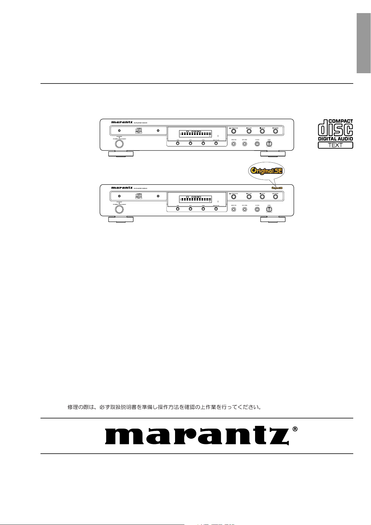
CD Player
Original SE badge
Please use this service manual with referring to the user guide ( D.F.U. ) without fail.
CD5001 / CD5001 OSE
Part no. 90M45BW855010
First Issue 2005.07
MZ
Page 2
MARANTZ DESIGN AND SERVICE
Using superior design and selected high grade components,
Only original
MARANTZ
parts can insure that your
MARANTZ
MARANTZ
product will continue to perform to the specifi cations for which
company has created the ultimate in stereo sound.
it is famous.
Parts for your
MARANTZ
ORDERING PARTS :
equipment are generally available to our National Marantz Subsidiary or Agent.
Parts can be ordered either by mail or by Fax.. In both cases, the correct part number has to be specifi ed.
The following information must be supplied to eliminate delays in processing your order :
1. Complete address
2. Complete part numbers and quantities required
3. Description of parts
4. Model number for which part is required
5. Way of shipment
6. Signature : any order form or Fax. must be signed, otherwise such part order will be considered as null and void.
USA
MARANTZ AMERICA, INC
1100 MAPLEWOOD DRIVE
ITASCA, IL. 60143
USA
PHONE : 630 - 741 - 0300
FAX : 630 - 741 - 0301
AUSTRALIA
QualiFi Pty Ltd,
24 LIONEL ROAD,
MT. WAVERLEY VIC 3149
AUSTRALIA
PHONE : +61 - (0)3 - 9543 - 1522
FAX : +61 - (0)3 - 9543 - 3677
EUROPE / TRADING
MARANTZ EUROPE B.V.
P. O. BOX 8744, BUILDING SILVERPOINT
BEEMDSTRAAT 11, 5653 MA EINDHOVEN
THE NETHERLANDS
PHONE : +31 - 40 - 2507844
FAX : +31 - 40 - 2507860
THAILAND
MRZ STANDARD CO., LTD
746 - 754 MAHACHAI ROAD.,
WANGBURAPAPIROM, PHRANAKORN,
BANGKOK, 10200 THAILAND
PHONE : +66 - 2 - 222 9181
FAX : +66 - 2 - 224 6795
CANADA
MARANTZ CANADA INC.
5-505 APPLE CREEK BLVD.
MARKHAM, ONTARIO L3R 5B1
CANADA
PHONE : 905 - 415 - 9292
FAX : 905 - 475 - 4159
SINGAPORE
WO KEE HONG DISTRIBUTION PTE LTD
No.1 JALAN KILANG TIMOR
#08-03 PACIFIC TECH CENTRE
SINGAPORE 159303
PHONE : +65 6376 0338
FAX : +65 6376 0166
NEW ZEALAND
WILDASH AUDIO SYSTEMS NZ
14 MALVERN ROAD MT ALBERT
AUCKLAND NEW ZEALAND
PHONE : +64 - 9 - 8451958
FAX : +64 - 9 - 8463554
JAPAN
D&M Holdings Inc.
35- 1, 7- CHOME, SAGAMIONO
SAGAMIHARA - SHI, KANAGAWA
JAPAN 228-8505
PHONE : +81 42 748 1013
FAX : +81 42 741 9190
Technical
TAIWAN
PAI- YUING CO., LTD.
6 TH FL NO, 148 SUNG KIANG ROAD,
TAIPEI, 10429, TAIWAN R.O.C.
PHONE : +886 - 2 - 25221304
FAX : +886 - 2 - 25630415
SHOCK, FIRE HAZARD SERVICE TEST :
MALAYSIA
WO KEE HONG ELECTRONICS SDN. BHD.
2ND FLOOR BANGUNAN INFINITE CENTRE
LOT 1, JALAN 13/6, 46200 PETALING JAYA
SELANGOR DARUL EHSAN, MALAYSIA
PHONE : +60 - 3 - 7954 8088
FAX : +60 - 3 - 7954 7088
KOREA
MARANTZ KOREA CO., LTD.
ROOM 604, ELECTRO OFFICE, 16-58,
HANGGANG-RO 3GA, YONGSAN-KU,
SEOUL, 140-013, KOREA
PHONE : +82 - 2 - 323 - 2155
FAX : +82 - 2 - 323 - 2154
CAUTION : After servicing this appliance and prior to returning to customer, measure the resistance between either primary AC
cord connector pins ( with unit NOT connected to AC mains and its Power switch ON ), and the face or Front Panel of product
and controls and chassis bottom.
Any resistance measurement less than 1 Megohms should cause unit to be repaired or corrected before AC power is applied,
and verifi ed before it is return to the user/customer.
Ref. UL Standard No. 1492.
In case of diffi culties, do not hesitate to contact the Technical
Department at above mentioned address.
050616MZ
Page 3
440
515 72
87 283
9269
DISC
TTL
TRK
PEAK
TTL
TIME
RNDM
RROGA–
B RPT1
PITCH
EDIT
TEXT
1234 56 789101112131415161718 1920
1. TECHNICAL SPECIFICATIONS
Audio characteristics
Channels ........................................................... 2 channels
Frequency response.................................... 2 Hz to 20 kHz
Dynamic range ........................................................ 100 dB
Signal-to-noise ratio ................................................ 110 dB
Channel separation .....................................100 dB (1 kHz)
Harmonic distortion ..................................0.0025% (1 kHz)
Wow & fl utter .........................................Precision of quartz
Error correction system ................... Cross-interleave Reed
Solomon code (CIRC)
Audio output .............................................2.0 V rms, stereo
Headphone output.... 18 mW/32 ohms (variable maximum)
Digital output
Coaxial output (pin jack) ........................0.5 Vp-p, 75 ohm
Optical output (square optical connector) ........... -19 dBm
Optical readout system
Laser .............................................. AlGaAs semiconductor
Wavelength..............................................................780 nm
Signal system
Sampling frequency...............................................44.1 kHz
Quantization ....................................... 16-bit linear/channel
Power supply
F version............................................. AC 100 V 50 /60 Hz
K version .................................................. AC 220 V 50 Hz
L version................................................... AC 110 V 60 Hz
N version ................................................... AC 230 V 50 Hz
U version ................................................... AC 120 V 60 Hz
Power consumption.....................................................14 W
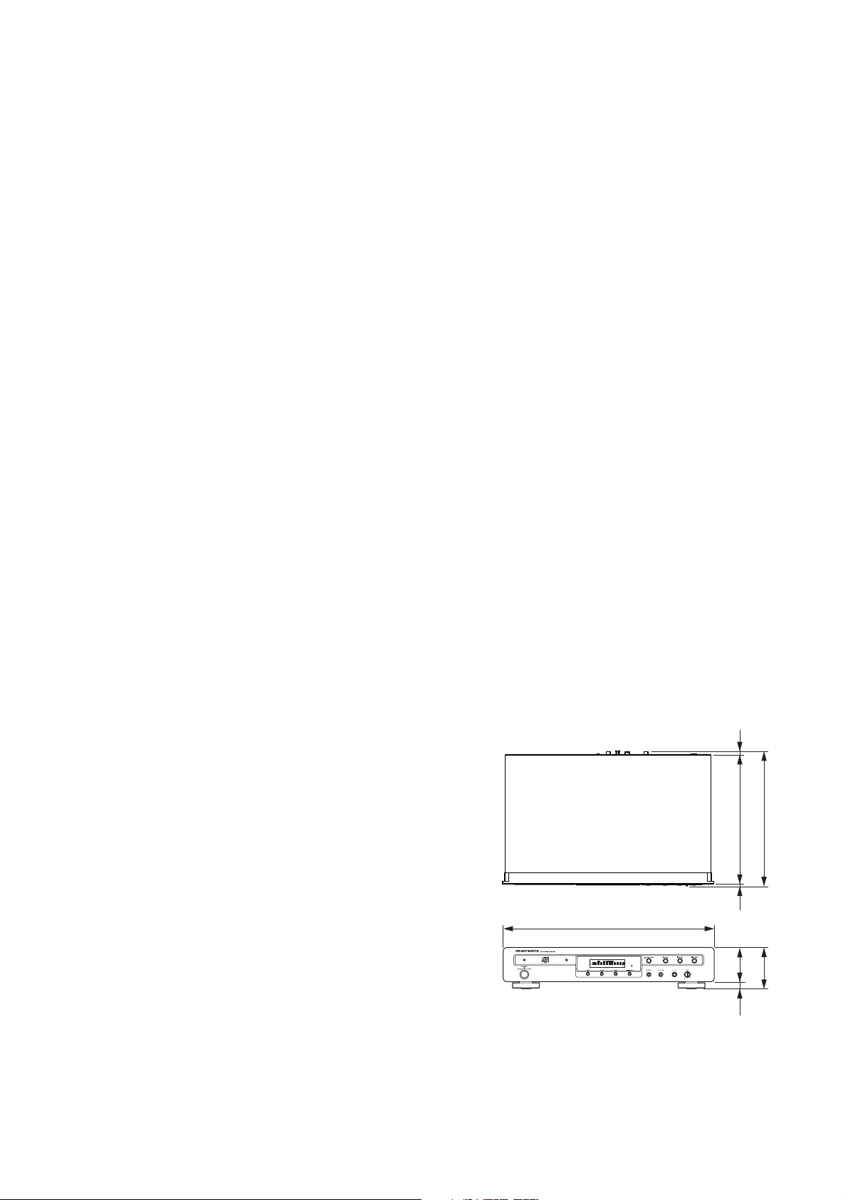
Cabinet, etc.
Maximum dimensions........... 440(W) x 87(H) x 283(D) mm
17-5/16(W) x 3-1/2(H) x 11-1/8(D) inch
Weight ....................................................................... 4.0 kg
8.82 Ibs
Allowable operating temperature.....................+5 to +35 °C
Allowable operating humidity..5 to 90 % (no condensation)
1
Page 4
2. SERVICE HINTS AND TOOLS
SERVICE HINTS
SERVICE TOOLS
Audio signals disc 4822 397 30184
Disc without errors (SBC444)+Disc with DO errors,
black spots and fingerprints (SBC444A) 4822 397 30245
Disc (65 min 1kHz) without no pause 4822 397 30155
Max. diameter disc (58.0 mm) 4822 397 60141
13th order filter
2
4822 395 30204
Page 5
3. WARNING AND LASER SAFETY INSTRUCTIONS
GB
WARNING
All ICs and many other semi-conductors are
susceptible to electrostatic discharges (ESD).
Careless handling during repair can reduce
life drastically.
When repairing, make sure that you are
connected with the same potential as the
mass of the set via a wrist wrap with
resistance.
Keep components and tools also at this
potential.
F
ATTENTION
D
WARNUNG
I
WAARSCHUWING
AVVERTIMENTO
NL
Alle IC’s en vele andere halfgeleiders zijn
gevoelig voor elektrostatische ontladingen
(ESD).
Onzorgvuldig behandelen tijdens reparatie
kan de levensduur drastisch doen
verminderen.
Zorg ervoor dat u tijdens reparatie via een
polsband met weerstand verbonden bent met
hetzelfde potentiaal als de massa van het
apparaat.
Houd componenten en hulpmiddelen ook op
ditzelfde potentiaal.
Tous les IC et beaucoup d’autres semiconducteurs sont sensibles aux décharges
statiques (ESD).
Leur longévité pourrait être considérablement
écourtée par le fait qu’aucune précaution
n’est prise a leur manipulation.
Lors de réparations, s’assurer de bien être
relié au même potentiel que la masse de
l’appareil et enfiler le bracelet serti d’une
résistance de sécurité.
Veiller a ce que les composants ainsi que les
outils que l’on utilise soient également a ce
potentiel.
GB
Safety regulations require that the set be restored to its original condition
and that parts which are identical with those specified be used.
NL
Veiligheidsbepalingen vereisen, dat het apparaat in zijn oorspronkelijke
toestand wordt terug gebracht en dat onderdelen, identiek aan de
gespecifieerde worden toegepast.
Alle IC und viele andere Halbleiter sind
empfindlich gegen elektrostatische
Entladungen (ESD).
Unsorgfältige Behandlung bei der Reparatur
kann die Lebensdauer drastisch vermindern.
Sorgen sie dafür, das Sie im Reparaturfall
über ein Pulsarmband mit Widerstand mit
dem Massepotential des Gerätes verbunden
sind.
Halten Sie Bauteile und Hilfsmittel ebenfalls
auf diesem Potential.
D
Bei jeder Reparatur sind die geltenden Sicherheitsvorschriften zu beachten.
Der Originalzustand des Gerats darf nicht verandert werden.
Fur Reparaturen sind Original-Ersatzteile zu verwenden.
I
Le norme di sicurezza esigono che l’apparecchio venga rimesso nelle
condizioni originali e che siano utilizzati pezzi di ricambiago idetici a quelli
specificati.
Tutti IC e parecchi semi-conduttori sono
sensibili alle scariche statiche (ESD).
La loro longevita potrebbe essere fortemente
ridatta in caso di non osservazione della piu
grande cauzione alla loro manipolazione.
Durante le riparazioni occorre quindi essere
collegato allo stesso potenziale che quello
della massa dell’apparecchio tramite un
braccialetto a resistenza.
Assicurarsi che i componenti e anche gli
utensili con quali si lavora siano anche a
questo potenziale.
F
“Pour votre sécurité, ces documents
doivent être utilisés par des
spécialistes agrées, seuls habilités à
réparer votre appareil en panne.”
Les normes de sécurité exigent que l’appareil soit remis a l’état d’origine et
que soient utilisées les pièces de rechange identiques à celles spécifiées.
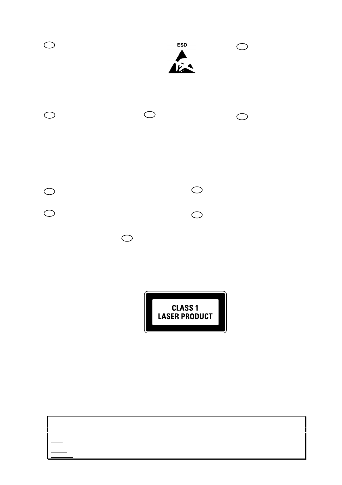
LASER SAFETY
This unit employs a laser. Only a qualified service person should remove the cover or attempt to service this
device, due to possible eye injury.
USE OF CONTROLS OR ADJUSTMENTS OR PERFORMANCE OF PROCEDURE OTHER THAN THOSE
SPECIFIED HEREIN MAY RESULT IN HAZARDOUS RADIATION EXPOSURE.
AVOID DIRECT EXPOSURE TO BEAM
WARNING
The use of optical instruments with this product will increase eye hazard.
Repair handling should take place as much as possible with a disc loaded inside the player
WARNING LOCATION: INSIDE ON LASER COVERSHIELD
CAUTION VISIBLE AND INVISIBLE LASER RADIATION WHEN OPEN AVOID EXPOSURE TO BEAM
ADVARSEL SYNLIG OG USYNLIG LASERSTRÅLING VED ÅBNING UNDGÅ UDS
ADVARSEL SYNLIG OG USYNLIG LASERSTRÅLING NÅR DEKSEL Å PNES UNNGÅ EKSPONERING FOR STRÅLEN
VARNING SYNLIG OCH OSYNLIG LASERSTRÅLNING NÄR DENNA DEL ÄR ÖPPNAD BETRAKTA EJ STRÅLEN
VARO! AVATT AESSA OLET ALTTIINA NÄKYVÄLLE JA NÄKYMÄTTÖMÄLLE LASER SÄTEILYLLE. ÄLÄ KATSO SÄTEESEEN
VORSICHT SICHTBARE UND UNSICHTBARE LASERSTRAHLUNG WENN ABDECKUNG GEÖFFNET NICHT DEM STRAHL AUSSETSEN
DANGER VISIBLE AND INVISIBLE LASER RADIATION WHEN OPEN AVOID DIRECT EXPOSURE TO BEAM
ATTENTION RAYONNEMENT LASER VISIBLE ET INVISIBLE EN CAS D'OUVERTURE EXPOSITION DANGEREUSE AU FAISCEAU
Æ
TTELSE FOR STRÅLING
3
Page 6
4. SERVICE MODE AND EMERGENCY DISC EJECT
SERVICE MODE
1. Insert mains cable plug in the outlet and press POWER button.
2. Press the OPEN/CLOSE button to open the tray.
3. Press the TIME button for about fi ve seconds.
4. The version number of the microprocessor is displayed Ex: 03-19-1.
5. Press the EDIT button for about fi ve seconds.
6. Light up all the FL segment.
Turn off power to quit Service mode.
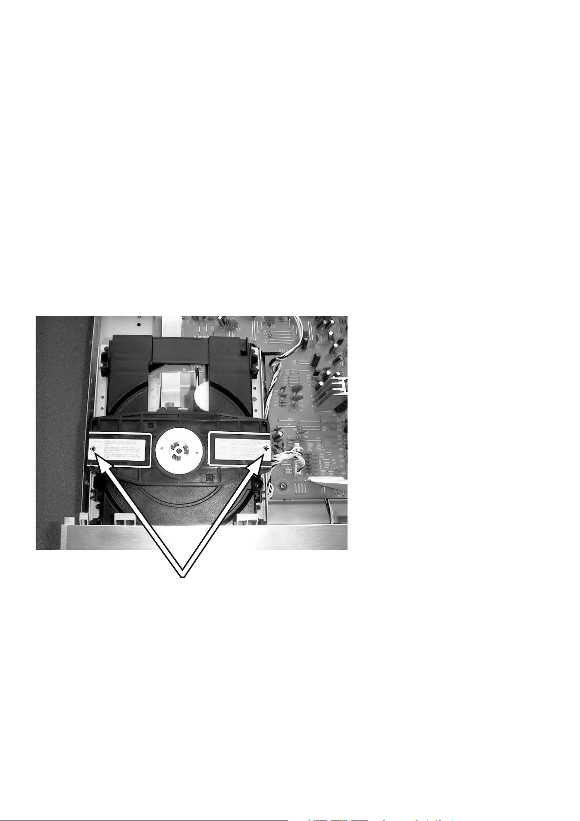
EMERGENCY DISC EJECT
1. Remove the top cover of the plyer.
2. Remove 2 screws under the label shown in the picture follows.
3. Remove the disc clamper.
4. Now you can remove the disc.
Remove those screws
4
Page 7
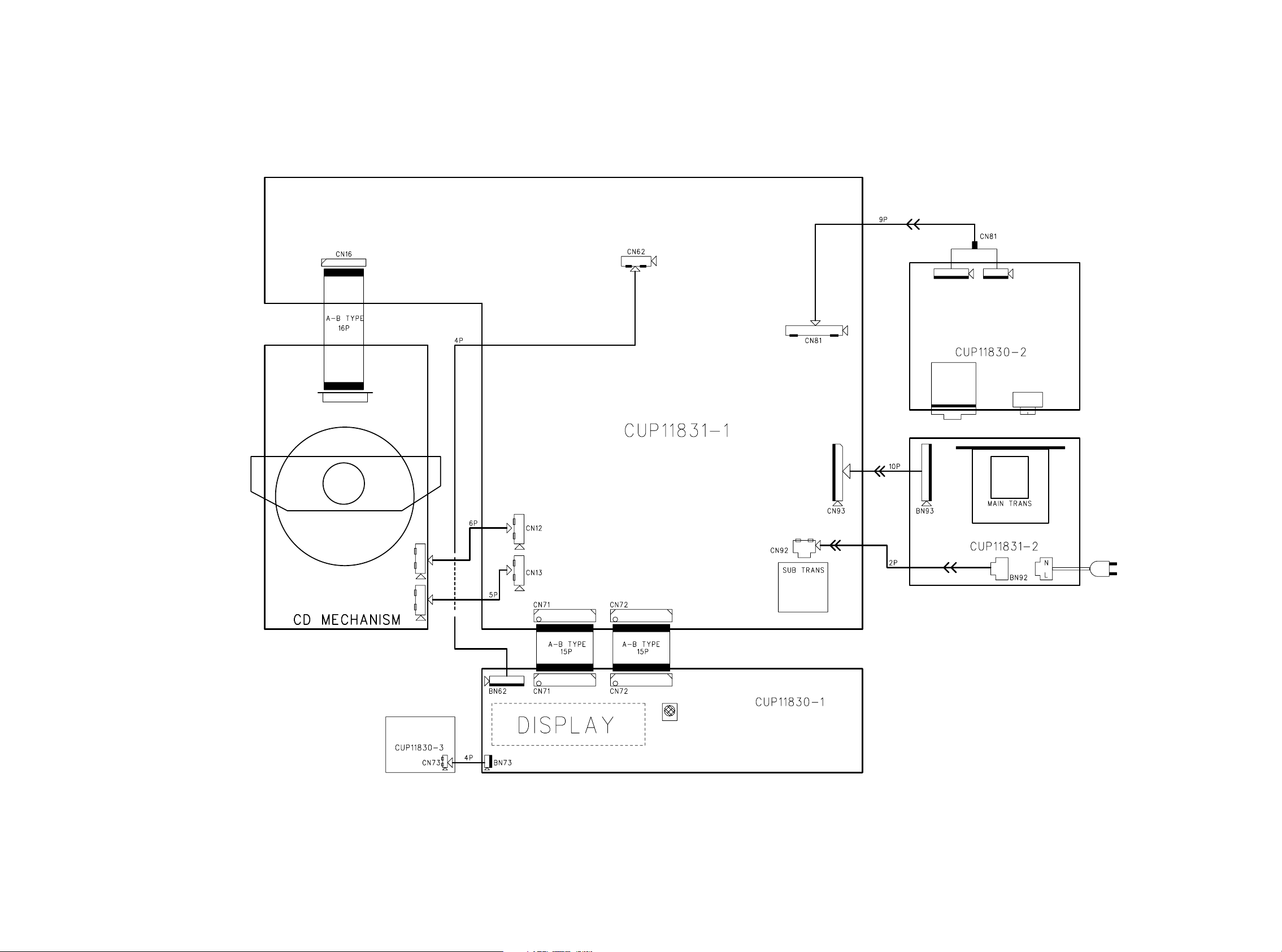
5. WIRING DIAGRAM
MAIN PWB
BN81-1
BN81-2
H/P(HEADPHONE)
PWB
MAIN TRANSF. PWB
MAINS
FRONT PWB
POWER SW
PWB
5 6
Page 8
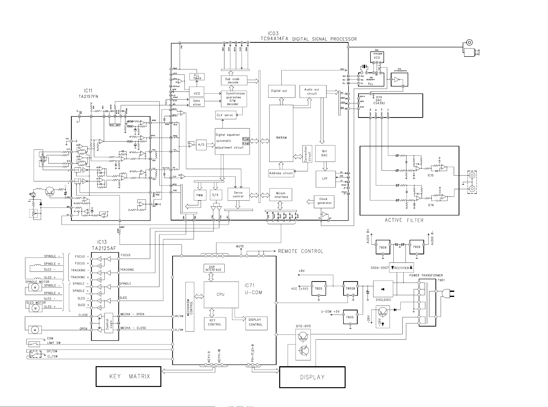
6. BLOCK DIAGRAM
JK52
OPTICAL OUT
COAXIAL OUT
JK51
JK53
MAINS IN
AUDIO OUT
87
Page 9
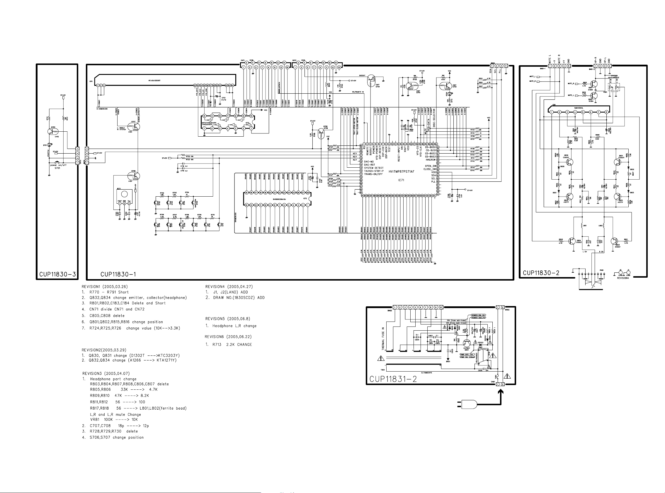
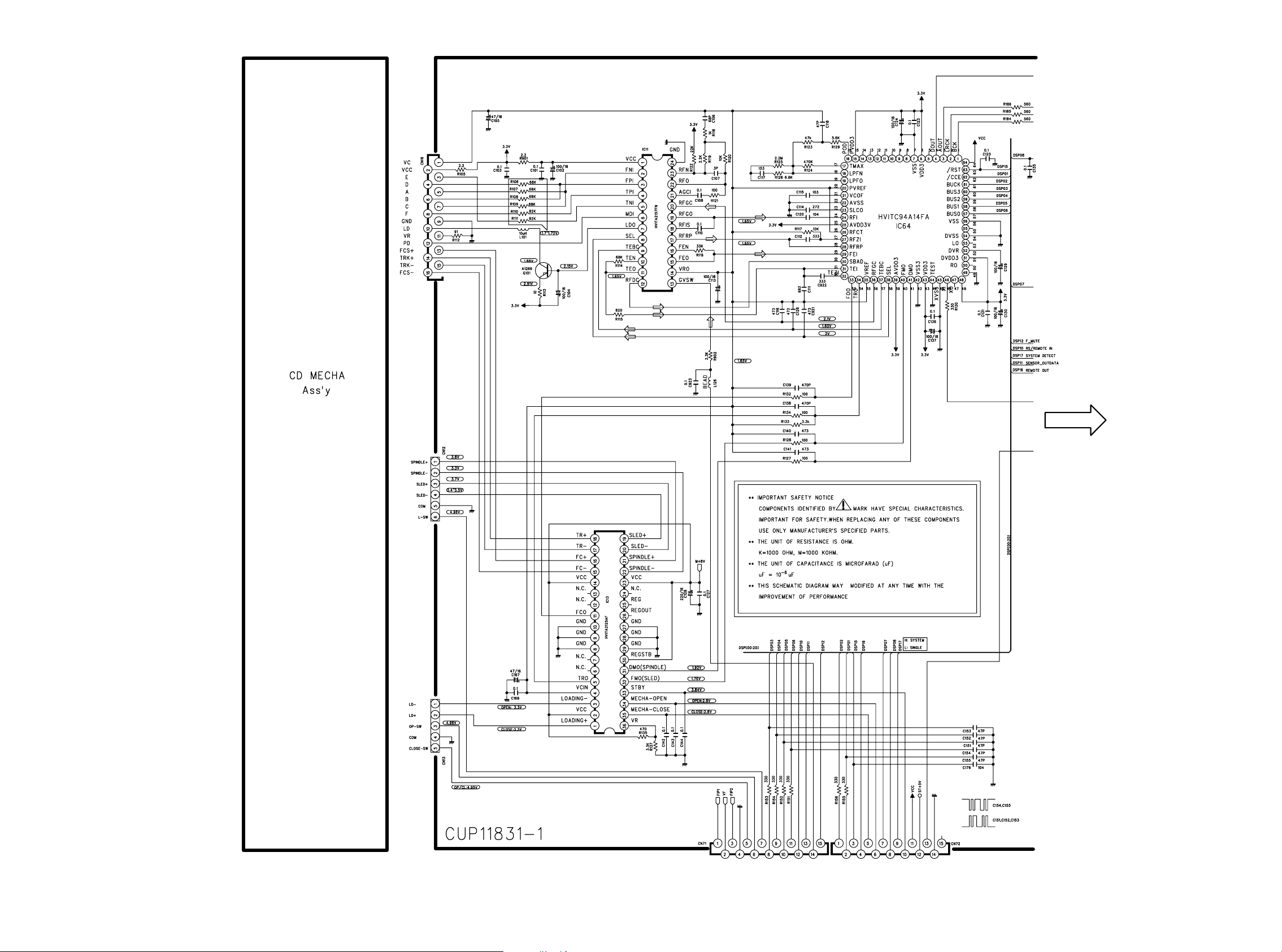
7. SCHEMATIC DIAGRAM
1.5k
RLS4148SR
RLS4148SR
RLS4148SR
RLS4148SR
L801, L802 :
BEAD [/L /U]
0 ohm [/F /K /N]
MAINS IN
TO MAIN PWB (CN71) TO MAIN PWB (CN72) TO MAIN PWB (CN62)
TO MAIN PWB (CN93)
TO MAIN PWB (CN81)
TO MAIN PWB (CN92)
POWER
SW
PWB
F901 : T 630mA 250V [/F /L /U }
F901 : T 315mA 250V [/K /N]
FRONT PWB
H/P (HEADPHONE)
PWB
MAIN TRANSF. PWB
9 10
Page 10
MAIN
PWB - 2/2
TO FRONT PWB (CM71) TO FRONT PWB (CN72)
MAIN PWB - 1/2
CD MECHANISM
1211
Page 11
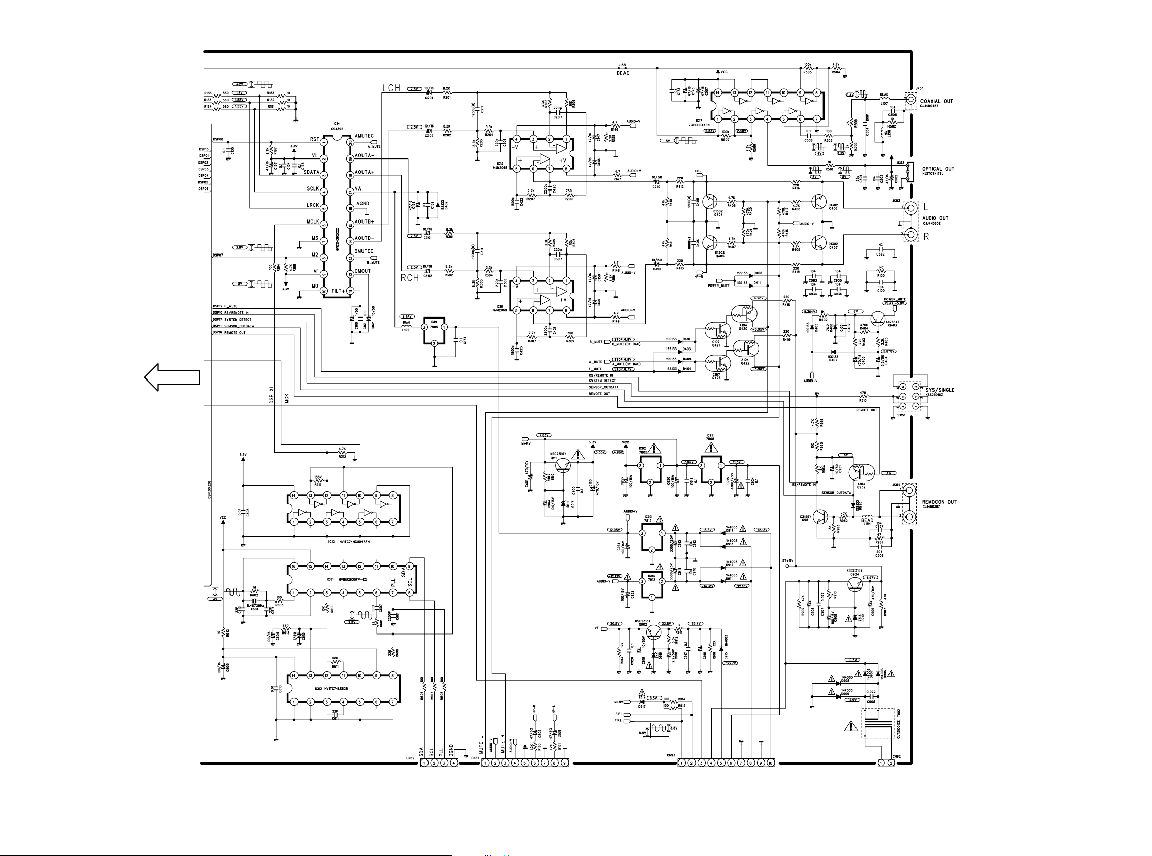
MAIN PWB - 2/2
MAIN
PWB - 1/2
470/25V
22/63V
TO FRONT PWB (BN62)
13 14
TO MAIN TRANSF. PWB (BN93)TO H/P(HEADPHONE) PWB (BN82) TO MAIN TRANSF. PWB (CN92)
T902 : CLT51001ZJ [/F]
T902 : CLT51001ZU [/L /U]
T902 : CLT51001ZE [/K /N]
Page 12
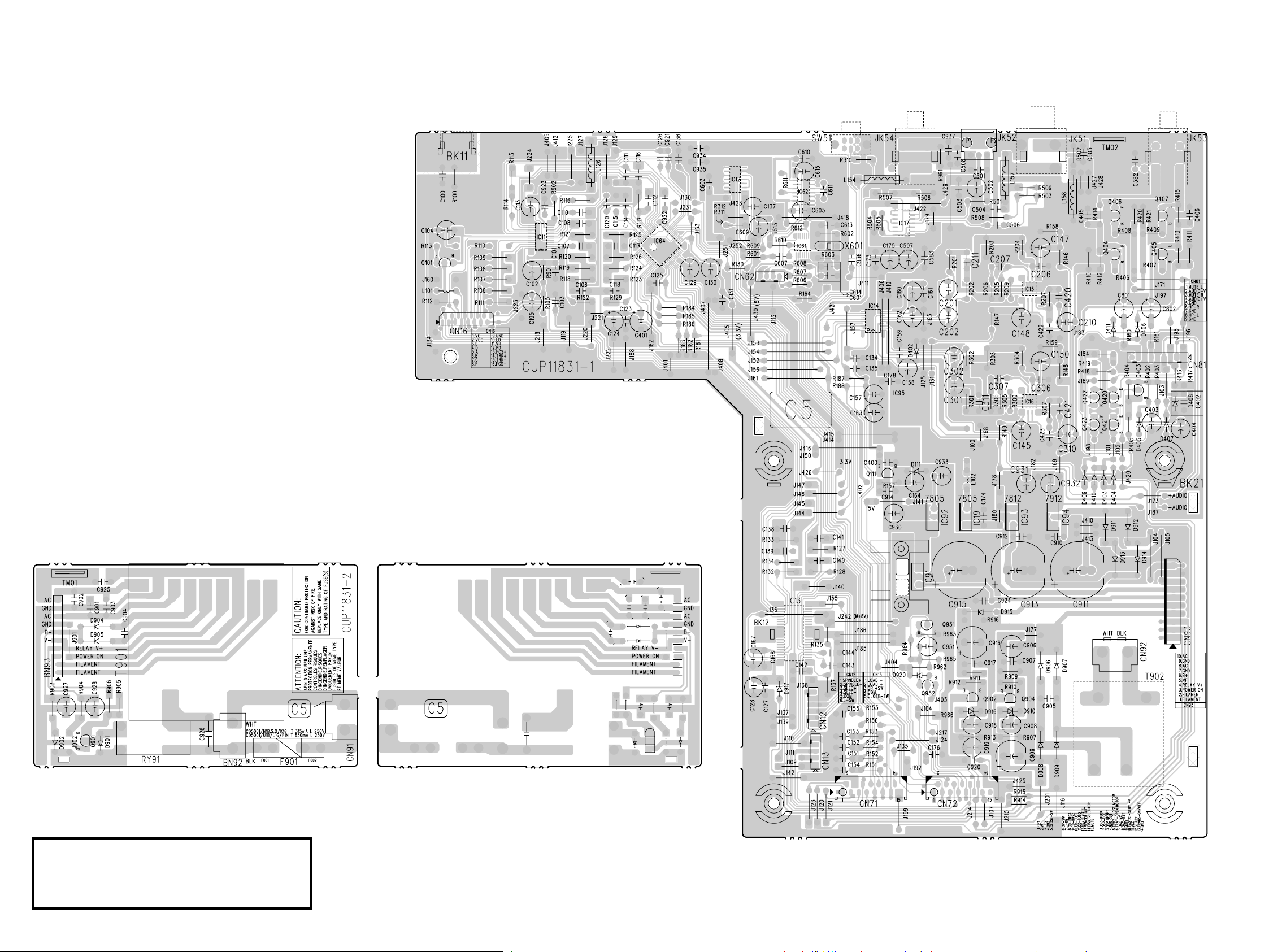
8. PARTS LOCATION
MAIN TRANSF. B
ᤲȕȪȸҞဋ
MAIN A
Q101
Q111
IC91 IC92 IC19 IC93 IC94
Q951 Q952
Q902 Q904
Q404 - Q407
Q420 - Q423 Q403
MAIN TRANSF. A
Q901
ᤲȕȪȸҞဋ
Ҟဋ˄ƚƴƸŴᤲȕȪȸҞဋ
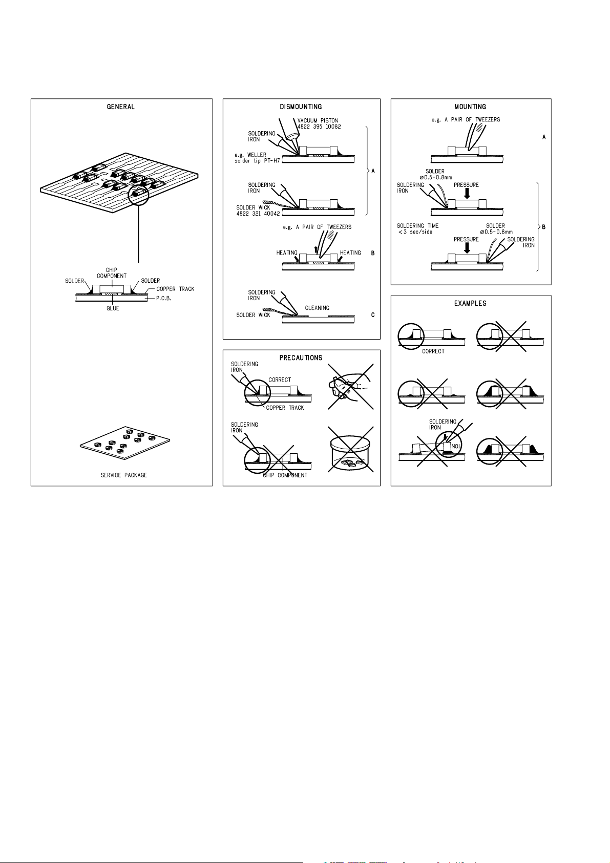
Sn-Ag-Cu
ǛဇƠƯƘƩƞƍŵ
Lead-free Solder
When soldering, use the Lead-free Solder (Sn-Ag-Cu).
1615
Page 13
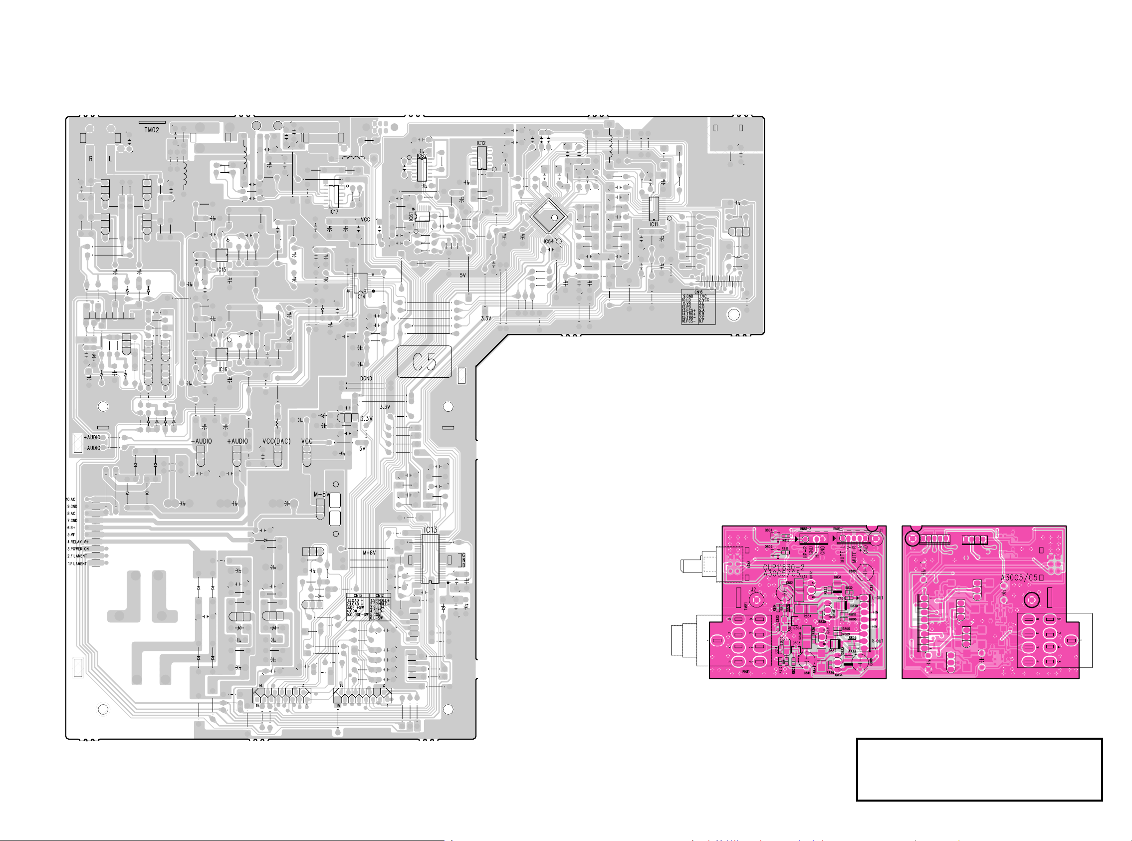
MAIN B
ᤲȕȪȸҞဋ
H/P(HEADPHONE) B
IC17
IC15 IC14
IC16
IC61 IC62 IC12 IC64 IC11
IC13
H/P(HEADPHONE) A
Q801 Q802
Q804 Q832 Q830
Q803 Q831 Q834
ᤲȕȪȸҞဋ
Ҟဋ˄ƚƴƸŴᤲȕȪȸҞဋ
Sn-Ag-Cu
ǛဇƠƯƘƩƞƍŵ
17 18
Lead-free Solder
When soldering, use the Lead-free Solder (Sn-Ag-Cu).
Page 14
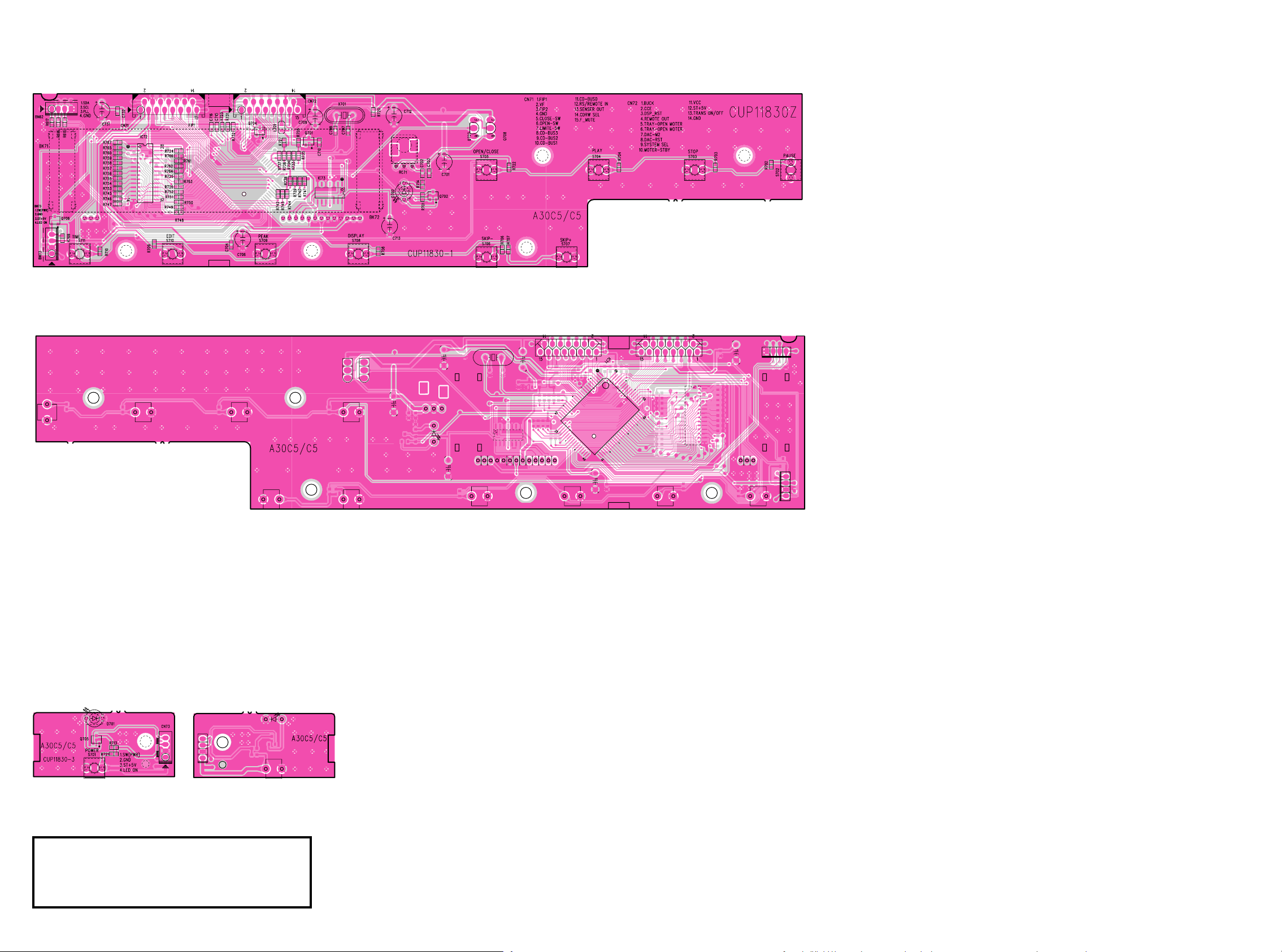
FRONT A
ᤲȕȪȸҞဋ
Q706
FRONT B
IC72
Q704
Q701 IC73
Q702 Q707 Q708
IC71
POWER SW A
Q705
ᤲȕȪȸҞဋ
Ҟဋ˄ƚƴƸŴᤲȕȪȸҞဋ
POWER SW B
Sn-Ag-Cu
ǛဇƠƯƘƩƞƍŵ
Lead-free Solder
When soldering, use the Lead-free Solder (Sn-Ag-Cu).
2019
Page 15
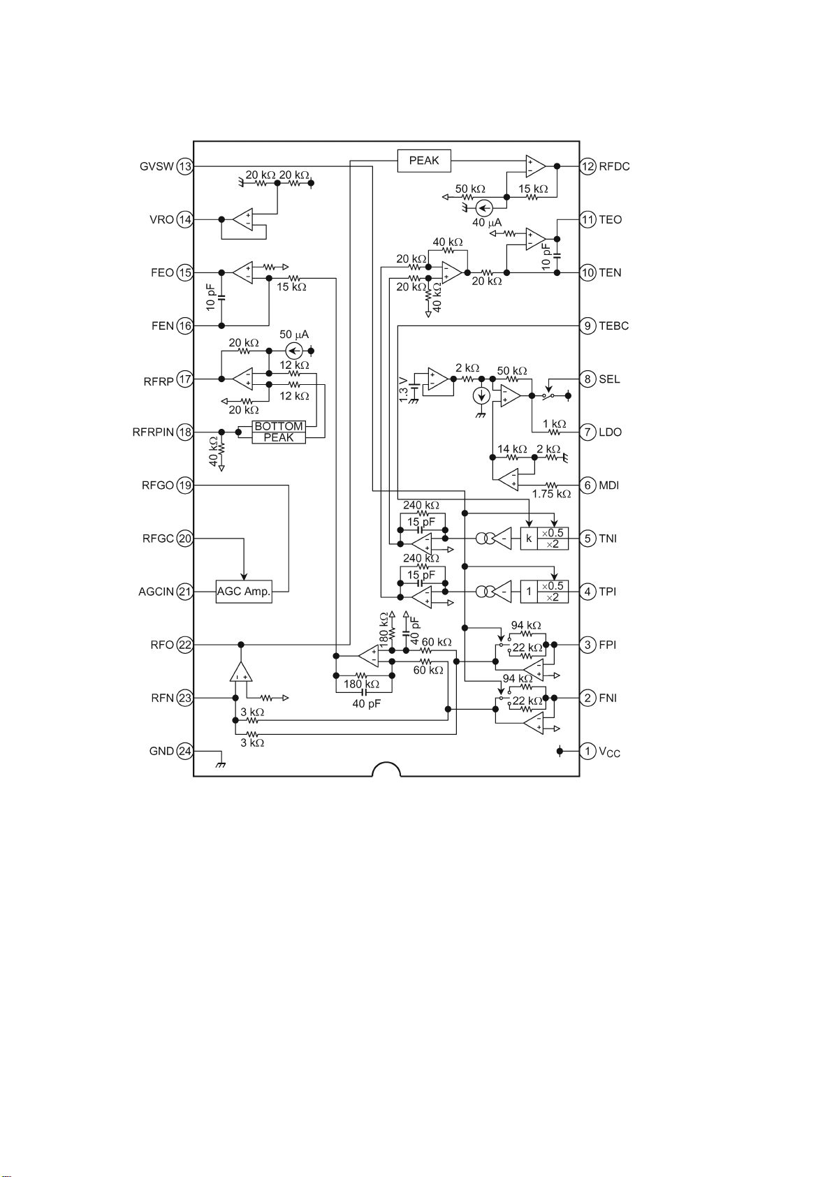
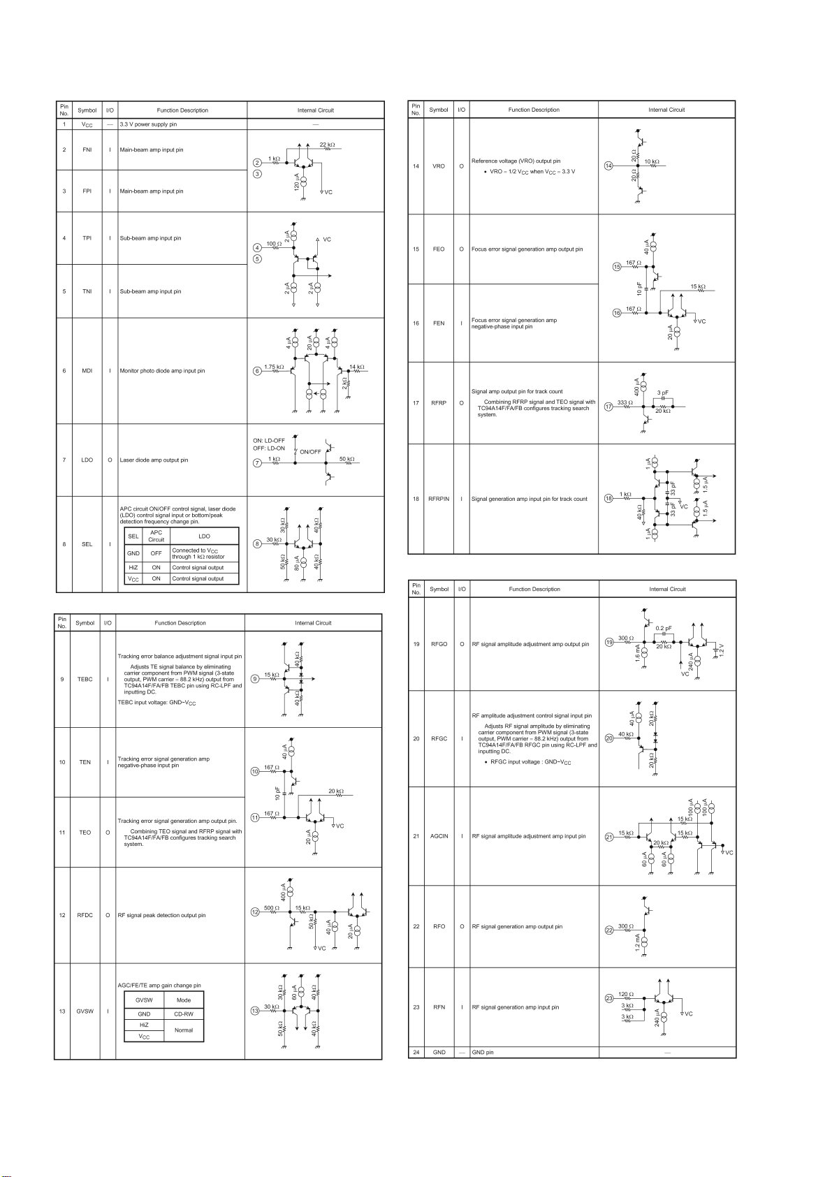
9. MICROPROCESSOR AND IC DATA
IC11 : TA2157FN
21
Page 16
IC11 : TA2157FN
22
Page 17
IC13 : TA2125AF
IC13 : TA2125AF
23
Page 18

IC14 : CS4392KS
M1
(SDA/CDIN)
RST
SCLK
LRCK
SDATA
SERIAL
PORT
RST AMUTEC
VL AOUTA-
SDATA AOUTA+
SCLK VA
LRCK AGND
MCLK AOUTB+
M3 AOUTB-
(SCL/CCLK) M2 BMUTEC
(SDA/CDIN) M1 CMOUT
(AD0/CS
)M0 FILT+
M3
MODE SELECT
(CONTROL P ORT)
1
2
3
4
5
6
7
8
9
10
M2
(SCL/CCLK) (AD0/CS)
VOLUM E
CONTROL
MIXER
VOLUM E
CONTROL
20
19
18
17
16
15
14
13
12
11
M0
AMUTEC
MUTE CONTROL
INTERPOLATION
FILTER
INTERPOLATION
FILTER
EXTERNAL
MCLK
ΔΣ
DAC
ΔΣ
DAC
CMOUT
REFERENCE
FILT+BMUTEC
ANALOG
FILTER
ANALOG
FILTER
AOUTA+
AOUTA-
AOUTB+
AOUTB-
RST 1 Reset (Input) - Powers down device and resets all internal registers to their default settings.
VL 2 Logic Power (Input) - Positive power for the digital input/output.
SDATA 3 Serial Audio Data (Input) - Input for two’s complement serial audio data.
SCLK 4 Serial Clock (Input/Output) - Serial clock for the serial audio interface.
LRCK 5 Left Right Clock (Input/Output) - Determines which channel, Left or Right, is currently active on the
serial audio data line.
MCLK 6 Master Clock (Input) - Clock source for the delta-sigma modulator and digital filters.
FILT+ 11 Positive Voltage Reference (Output) - Positive reference voltage for the i nternal sampling circuits.
CMOUT 12 Common Mode Voltage (Output) - Filter connection for internal quiescent voltage.
AMUTEC
BMUTEC2013
AOUTBAOUTB+
AOUTA+
AOUTA
Mute Control (Output) - The Mute Control pin goes high during power-up initialization, reset, muting,
power-down or if the master clock to left/right clock frequency ratio is incorrect.
14
Differential Analog Output (Outputs) - The full scale differential analog output level is specified in the
15
Analog Characteristics specification table.
18
19
AGND 16 Ground (Input)
VA
17 Analog Power (Input) - Positive power for the analog section.
Control Port Mode Definitions
M3
SCL/CCLK 8
SDA/CDIN 9 Serial Control Data (Input/Output) - SDA is a data I/O line in I
7 Mode Selection (Input) - This pins should be tied to GND level during control port mode.
Serial Control Port Clock (Input) - Serial clock for the serial control port.
2
C mode. CDIN is the input data line for
the control port interface in SPI mode.
AD0/CS
10 Address Bit 0 (I2C) / Control Port Chip Select (SPI) (Input/Output) - AD0 is a chip address pin in I2C
mode; CS
is the chip select signal for SPI format.
Stand-Alone Mode Definitions
Mode Selection (Input) - Determines the operational mode of the device.
M3
M2
M1
M0
7
8
9
10
24
Page 19

IC61 : BU2630
25
Page 20

IC62 : TC74LS628
26
Page 21

IC64 : TC94A14FA
27
Page 22

IC64 : TC94A14FA
28
Page 23

IC71 : TMP87PS71AF
IC72 : IS61C256AH
PIN No. SYMBOL I/O FUNCTION DESCRIPTION
1 RS I REMOCON OUT
2 REMOTE I REMOCON CENSOR CONTROL
3 BUS OUT O GND
4 POWER O POWER CONTROL PORT
5 VFD-POWER O VFD POWER CONTROL PORT
6 DSP-RESET O DSP RESET CONTROL PORT
7 DSP-CCE O DSP CCE CONTROL PORT
8 DSP-BUCK O DSP BUCK CONTROL PORT
9 TEST - GND
12 RESET-INPUT - RESET INPUT PORT
13 XIN - 8MHz Cystal CONNECTION PORT
14 XOUT 15 VSS - GND
18 VFD-CS O VFD CS CONTROL PORT
19 VFD-CLK O VFD CLK CONTROL PORT
20 MUTE O MUTE
21 VFD-DATA O VFD DATA PORT
22 DISC-
SELECTOR
24 VCC O VCC
25 CD-BUS0 I/O
26 CD-BUS1 I/O
27 CD-BUS2 I/O
28 CD-BUS3 I/O
29 INNERSW I L-SWITCH
31 OPEN_SW I OPEN SWITCH
32 CLOSE_SW I CLOSE SWITCH
33 VDD - ST+5V
34 SDA - SDA
35 SCL - SCL
36 PLL - PLL
42 SRAM15 I/O
43 SRAM16 I/O
44 SRAM17 I/O
45 SRAM18 I/O
46 SRAM19 I/O
O GVSW
BUS CONTROL PORT
SRAM CONTROL PORT
PIN No. SYMBOL I/O FUNCTION DESCRIPTION
47 SRAM20 I/O
48 SRAM21 I/O
49 SRAM22 I/O
50 SRAM00 O
51 SRAM01 O
52 SRAM02 O
53 SRAM03 O
54 SRAM04 O
55 SRAM05 O
56 SRAM06 O
57 SRAM07 O
58 SRAM08 O
59 SRAM09
60 SRAM10 O
61 SRAM11 O
62 SRAM12 O
63 SRAM13 O
64 SRAM14 O
66 GND - GND
67 SRAM23 O
69 SRAM25 O
70 TRANS-ON/
OFF
71 TA2125-
STBY-P
72 RC-5
SELECTION
73 DAC-RST O DAC RESET PORT
74 DAC-M2 O DAC M2 PORT
76 KEY I ST+5V
77 KEY I ST+5V
78 KEY I BN72
79 TRAY-OPEN-
MOTOR
80 TRAY-CLOSE-
MOTOR
SRAM CONTROL PORT
SRAM CONTROL PORT68 SRAM24 O
O TRANS ON/OFF CONTROL PORT
O STAND BY PORT
I RC-5 SELECTION
O MECHA OPEN CONTROL PORT
O MECHA CLOSE CONTROL PORT
A0-A14
VCC
GND
I/O0-I/O7
CE
OE
WE
DECODER
I/O
DATA
CIRCUIT
CONTROL
CIRCUIT
MEMORY ARRAY
PIN DESCRIPTIONS
A0-A14 Address Inputs
CE Chip Enable Input
OE Output Enable Input
WE Write Enable Input
I/O0-I/O7 Bidirectional Ports
Vcc Power
GND Ground
TRUTH TABLE
OEOE
WEWE
Mode
WE
WEWE
Not Selected X H X High-Z I
(Power-down)
Output Disabled H L H High-Z ICC
Read H L L DOUT ICC
Write L L X DIN ICC
CECE
OE I/O Operation Vcc Current
CE
OEOE
CECE
IC81 : NJM4556AL
32K X 8
COLUMN I/O
SB1, ISB2
29 30
Page 24

10. EXPLODED VIEW AND PARTS LIST
31
19
LOADER ASSY
S8
X5
S1
S2
18
S2
9
8
S8
S4
10
16
FRONT PWB
17
S8
23
(MECHA LOADER)
(MECHA TRAVERSE)
S8
S8
25
S7
24
S7
27
S7
26
MAIN PCB
S1
30
X3
S9
S1
S7
X2
S5
X3
S8
31
29
POWER SW PWB
6
1
7
12
13
X4
S4
23
20
X2
S4
21
T901
21
11
2
S10
X5
3
5
4
X4
S9
S10
X3
S3
S8
32
X3
14
H/P(HEADPHONE) PWB
15
22
X2
S6
23
22
X2
S6
28
MAIN TRANSF. PWB
3231
Page 25

CD5001
(
)
(MZ)
p
p
/
p
/
p
/
/
/
/
p
p
p
/
p
/
p
/
/
/
/
p
p
p
/
p
/
p
/
/
/
/
p
p
p
/
p
/
p
/
/
/
/
p
p
K
p
/
p
/
p
/
K
/
/
/
p
K
p
K
p
/
p
/
p
/
K
/
/
/
p
K
p
K
p
/
p
/
p
/
K
/
/
/
p
K
p
p
/
p
/
p
/
/
/
/
p
pnsp
pnsp
P.C.B.
NAME
POS. NO.
VERS.
COLOR
1F B ns
1F N ns
K1G ns
1
L1G ns
1
N1B 00M24AW251010 00M24AW251010 BADGE NEW MZ BADGE CGB1A117
1
N1G 00M24AW251010 00M24AW251010 BADGE NEW MZ BADGE CGB1A117
1
N1S 00M24AW251020 00M24AW251020 BADGE NEW MZ BADGE SILVER CGB1A117G
1
U1B ns
1
2F B ns
2F N ns
K1G ns
2
L1G ns
2
N1B 00M45BW063010 00M45BW063010 ESCUTCHEON ORNAMENT DOOR BLACK CGR1A382ZH10
2
N1G 00M45BW063110 00M45BW063110 ESCUTCHEON ORNAMENT DOOR GOLD CGR1A382RFYH40
2
N1S 00M45BW063210 00M45BW063210 ESCUTCHEON ORNAMENT DOOR SILVER CGR1A382R6YH51
2
U1B ns
2
3F B ns
3F N ns
K1G ns
3
L1G ns
3
N1B 00M45BW158110 00M45BW158110 WINDOW WINDOW BLACK/GOLD CGU1A378Z
3
N1G 00M45BW158110 00M45BW158110 WINDOW WINDOW BLACK/GOLD CGU1A378Z
3
N1S 00M45BW158210 00M45BW158210 WINDOW WINDOW SILVER CGU1A378Y
3
U1B ns
3
4F B ns
4F N ns
K1G ns
4
L1G ns
4
N1B 00M45BW063020 00M45BW063020 ESCUTCHEON ORNAMENT KNOB BLACK CGR1A383ZH10
4
N1G 00M45BW063120 00M45BW063120 ESCUTCHEON ORNAMENT KNOB GOLD CGR1A383RFYH40
4
N1S 00M45BW063220 00M45BW063220 ESCUTCHEON ORNAMENT KNOB SILVER CGR1A383R6YH51
4
U1B ns
4
5F B ns
5F N ns
K1G ns
5
L1G ns
5
N1B 00M24AW154010 00M24AW154010 KNOB KNOB LEVEL BLAC
5
N1G 00M24AW154110 00M24AW154110 KNOB KNOB LEVEL GOLD CBN1A170RFD4
5
N1S 00M24AW154210 00M24AW154210 KNOB KNOB LEVEL SILVER CBN1A170R6G13
5
U1B ns
5
6F B ns
6F N ns
K1G ns
6
L1G ns
6
N1B 00M45BW248010 00M45BW248010 PANEL PANEL FRONT BLAC
6
N1G 00M45BW248110 00M45BW248110 PANEL PANEL FRONT GOLD CKM1A166YC24
6
N1S 00M45BW248210 00M45BW248210 PANEL PANEL FRONT SILVER CKM1A166YC40
6
U1B ns
6
7F B ns
7F N ns
K1G ns
7
L1G ns
7
N1B 00M45BW105010 00M45BW105010 CHASSIS PANEL SUB BLAC
7
N1G 00M45BW105110 00M45BW105110 CHASSIS PANEL SUB GOLD CGW1A410RFD4
7
N1S 00M45BW105210 00M45BW105210 CHASSIS PANEL SUB SILVER CGW1A410R6G13
7
U1B ns
7
8 00M24AW355010 00M24AW355010 LENS STANDBY CGL1A183
9F B ns
9F N ns
K1G ns
9
L1G ns
9
N1B 00M24AW270010 00M24AW270010 BUTTON KNOB POWER BLACK CBT1A878K92
9
N1G 00M24AW270110 00M24AW270110 BUTTON KNOB POWER GOLD CBT1A878RFD4
9
N1S 00M24AW270210 00M24AW270210 BUTTON KNOB POWER SILVER CBT1A878R6G13
9
U1B ns
9
10 F B ns
10 F N ns
PART NO.
FOR EUR
PART NO.
PART NAME DESCRIPTION
00M24AW251010 BADGE NEW MZ BADGE CGB1A117
00M24AW251010 BADGE NEW MZ BADGE CGB1A117
00M24AW251010 BADGE NEW MZ BADGE CGB1A117
00M24AW251010 BADGE NEW MZ BADGE CGB1A117
00M24AW251010 BADGE NEW MZ BADGE CGB1A117
00M45BW063010 ESCUTCHEON ORNAMENT DOOR BLACK CGR1A382ZH10
00M45BW063110 ESCUTCHEON ORNAMENT DOOR GOLD CGR1A382RFYH40
00M45BW063110 ESCUTCHEON ORNAMENT DOOR GOLD CGR1A382RFYH40
00M45BW063110 ESCUTCHEON ORNAMENT DOOR GOLD CGR1A382RFYH40
00M45BW063010 ESCUTCHEON ORNAMENT DOOR BLACK CGR1A382ZH10
00M45BW158110 WINDOW WINDOW BLACK/GOLD CGU1A378Z
00M45BW158110 WINDOW WINDOW BLACK/GOLD CGU1A378Z
00M45BW158110 WINDOW WINDOW BLACK/GOLD CGU1A378Z
00M45BW158110 WINDOW WINDOW BLACK/GOLD CGU1A378Z
00M45BW158110 WINDOW WINDOW BLACK/GOLD CGU1A378Z
00M45BW063020 ESCUTCHEON ORNAMENT KNOB BLACK CGR1A383ZH10
00M45BW063120 ESCUTCHEON ORNAMENT KNOB GOLD CGR1A383RFYH40
00M45BW063120 ESCUTCHEON ORNAMENT KNOB GOLD CGR1A383RFYH40
00M45BW063120 ESCUTCHEON ORNAMENT KNOB GOLD CGR1A383RFYH40
00M45BW063020 ESCUTCHEON ORNAMENT KNOB BLACK CGR1A383ZH10
00M24AW154010 KNOB KNOB LEVEL BLAC
CBN1A170K92
00M24AW154110 KNOB KNOB LEVEL GOLD CBN1A170RFD4
00M24AW154110 KNOB KNOB LEVEL GOLD CBN1A170RFD4
00M24AW154110 KNOB KNOB LEVEL GOLD CBN1A170RFD4
CBN1A170K92
00M24AW154010 KNOB KNOB LEVEL BLAC
00M45BW248010 PANEL PANEL FRONT BLAC
CBN1A170K92
CKM1A166ZC23
00M45BW248110 PANEL PANEL FRONT GOLD CKM1A166YC24
00M45BW248110 PANEL PANEL FRONT GOLD CKM1A166YC24
00M45BW248110 PANEL PANEL FRONT GOLD CKM1A166YC24
CKM1A166ZC23
00M45BW248010 PANEL PANEL FRONT BLAC
00M45BW105010 CHASSIS PANEL SUB BLAC
CKM1A166ZC23
CGW1A410R4K92
00M45BW105110 CHASSIS PANEL SUB GOLD CGW1A410RFD4
00M45BW105110 CHASSIS PANEL SUB GOLD CGW1A410RFD4
00M45BW105110 CHASSIS PANEL SUB GOLD CGW1A410RFD4
CGW1A410R4K92
00M45BW105010 CHASSIS PANEL SUB BLAC
CGW1A410R4K92
00M24AW270010 BUTTON KNOB POWER BLACK CBT1A878K92
00M24AW270110 BUTTON KNOB POWER GOLD CBT1A878RFD4
00M24AW270110 BUTTON KNOB POWER GOLD CBT1A878RFD4
00M24AW270110 BUTTON KNOB POWER GOLD CBT1A878RFD4
00M24AW270010 BUTTON KNOB POWER BLACK CBT1A878K92
PWB ASSY POWER SW PWB ASSY COP11830B
PWB ASSY POWER SW PWB ASSY COP11830B
NOTE : "nsp" PART IS LISTED FOR REFERENCE ONLY, MARANTZ WILL NOT SUPPLY THESE PARTS.
33
Page 26

CD5001
(
)
(MZ)
pnsp
/
pnsp
/
pnsp
/
pnsp
/
pnsp
/
pnsp
pnsp
p
K
p
/
p
/
p
/
K
/
/
/
p
K
p
K
p
/
p
/
p
/
K
/
/
/
p
K
pnsp
pnsp
/
pnsp
/
pnsp
/
pnsp
/
pnsp
/
pnsp
/
pnsp
pnsp
pnsp
/
pnsp
/
pnsp
/
pnsp
/
pnsp
/
pnsp
/
pnsp
pnsp
pnsp
p
p
/
p
/
p
/
/
/
/
p
pnsp
pnsp
pnsp
)
pnsp
pnsp
/
pnsp
/
pnsp
/
pnsp
/
pnsp
/
pnsp
/
pnsp
pnsp
pnsp
/
pnsp
/
pnsp
/
pnsp
P.C.B.
NAME
POS. NO.
VERS.
COLOR
10/K1G ns
L1G ns
10
N1B ns
10
N1G ns
10
N1S ns
10
U1B ns
10
11 ns
12 F B ns
12 F N ns
K1G ns
12
L1G ns
12
N1B 00M24AW270050 00M24AW270050 BUTTON KNOB DISPLAY BLAC
12
N1G 00M24AW270150 00M24AW270150 BUTTON KNOB DISPLAY GOLD CBT1A879RFD4
12
N1S 00M24AW270250 00M24AW270250 BUTTON KNOB DISPLAY SILVER CBT1A879R6G13
12
U1B ns
12
13 F B ns
13 F N ns
K1G ns
13
L1G ns
13
N1B 00M45BW270010 00M45BW270010 BUTTON KNOB SKIP BLAC
13
N1G 00M45BW270110 00M45BW270110 BUTTON KNOB SKIP GOLD CBT1A966RFD4
13
N1S 00M45BW270210 00M45BW270210 BUTTON KNOB SKIP SILVER CBT1A966R6G13
13
U1B ns
13
14 F B ns
14 F N ns
K1G ns
14
L1G ns
14
N1B ns
14
N1G ns
14
N1S ns
14
U1B ns
14
16 F B ns
16 F N ns
K1G ns
16
L1G ns
16
N1B ns
16
N1G ns
16
N1S ns
16
U1B ns
16
17 ns
PART NO.
FOR EUR
PART NO.
PART NAME DESCRIPTION
PWB ASSY POWER SW PWB ASSY COP11830B
PWB ASSY POWER SW PWB ASSY COP11830B
PWB ASSY POWER SW PWB ASSY COP11830B
PWB ASSY POWER SW PWB ASSY COP11830B
PWB ASSY POWER SW PWB ASSY COP11830C
PWB ASSY POWER SW PWB ASSY COP11830B
SHEET CGX1A372Z
00M24AW270050 BUTTON KNOB DISPLAY BLAC
CBT1A879K92
00M24AW270150 BUTTON KNOB DISPLAY GOLD CBT1A879RFD4
00M24AW270150 BUTTON KNOB DISPLAY GOLD CBT1A879RFD4
00M24AW270150 BUTTON KNOB DISPLAY GOLD CBT1A879RFD4
CBT1A879K92
00M24AW270050 BUTTON KNOB DISPLAY BLAC
00M45BW270010 BUTTON KNOB SKIP BLAC
CBT1A879K92
CBT1A966K92
00M45BW270110 BUTTON KNOB SKIP GOLD CBT1A966RFD4
00M45BW270110 BUTTON KNOB SKIP GOLD CBT1A966RFD4
00M45BW270110 BUTTON KNOB SKIP GOLD CBT1A966RFD4
CBT1A966K92
00M45BW270010 BUTTON KNOB SKIP BLAC
CBT1A966K92
PWB ASSY H/P PWB ASSY COP11830B
PWB ASSY H/P PWB ASSY COP11830B
PWB ASSY H/P PWB ASSY COP11830B
PWB ASSY H/P PWB ASSY COP11830B
PWB ASSY H/P PWB ASSY COP11830B
PWB ASSY H/P PWB ASSY COP11830B
PWB ASSY H/P PWB ASSY COP11830C
PWB ASSY H/P PWB ASSY COP11830B
PWB ASSY FRONT PWB ASSY COP11830B
PWB ASSY FRONT PWB ASSY COP11830B
PWB ASSY FRONT PWB ASSY COP11830B
PWB ASSY FRONT PWB ASSY COP11830B
PWB ASSY FRONT PWB ASSY COP11830B
PWB ASSY FRONT PWB ASSY COP11830B
PWB ASSY FRONT PWB ASSY COP11830C
PWB ASSY FRONT PWB ASSY COP11830B
BUFFER CHG2A185
19 00M24AW304510 00M24AW304510 MECHANISM MECHA LOADER AND TRAVERSE CJDKSL2130CCM
20 ns
21 F B ns
21 F N ns
K1G ns
21
L1G ns
21
N1B 00M243W05701000M243W057010LEG LEG GOLD/BLACK CKL2A042H11
21
N1G 00M243W05701000M243W057010LEG LEG GOLD/BLACK CKL2A042H11
21
N1S 00M243W05721000M243W057210LEG LEG FOR SILVER CKL2A042H46
21
U1B ns
21
00M243W057010LEG LEG GOLD/BLACK CKL2A042H11
00M243W057010LEG LEG GOLD/BLACK CKL2A042H11
00M243W057010LEG LEG GOLD/BLACK CKL2A042H11
00M243W057010LEG LEG GOLD/BLACK CKL2A042H11
00M243W057010LEG LEG GOLD/BLACK CKL2A042H11
CHASSIS CUA1A231
22 00M11BW056010 00M11BW056010 BUFFER RUBBER CUSHION KHG1A050
23 ns
24 ns
25 ns
26 F B ns
26 F N ns
K1G ns
26
L1G ns
26
N1B ns
26
N1G ns
26
N1S ns
26
U1B ns
26
28 F B ns
28 F N ns
K1G ns
28
L1G ns
28
N1B ns
28
BUFFER RUBBER CHG1A113
HOLDER HOLDER PWB CHE1A030
SUPPORT SJSS-13N(T
KRE1A057
PWB ASSY MAIN PWB ASSY COP11831D
PWB ASSY MAIN PWB ASSY COP11831D
PWB ASSY MAIN PWB ASSY COP11831C
PWB ASSY MAIN PWB ASSY COP11831B
PWB ASSY MAIN PWB ASSY COP11831C
PWB ASSY MAIN PWB ASSY COP11831C
PWB ASSY MAIN PWB ASSY COP11831C
PWB ASSY MAIN PWB ASSY COP11831B
PWB ASSY MAIN TRANSF. PWB ASSY COP11831D
PWB ASSY MAIN TRANSF. PWB ASSY COP11831D
PWB ASSY MAIN TRANSF. PWB ASSY COP11831C
PWB ASSY MAIN TRANSF. PWB ASSY COP11831B
PWB ASSY MAIN TRANSF. PWB ASSY COP11831C
NOTE : "nsp" PART IS LISTED FOR REFERENCE ONLY, MARANTZ WILL NOT SUPPLY THESE PARTS.
34
Page 27

CD5001
(
)
(MZ)
pnsp
/
pnsp
/
pnsp
pnsp
pnsp
/
pnsp
/
pnsp
/
pnsp
/
pnsp
/
pnsp
/
pnsp
p
A
p
A
p
A
p
A
A
A
A
p
A
p
p
/
p
V
Y
p
V
/
V
Y
V
Y
V
Y
p
pnsp
pnsp
p
pnsp
pnsp
p
p
p
p
/
p
K
/
p
K
/
/
/
/
p
p
p
/
p
/
p
/
p
/
p
/
p
/
p
p
p
)
p
)
/
p
)
/
p
)
/
p
)
/
p
)
/
p
)
/
p
)
p
P.C.B.
NAME
POS. NO.
VERS.
COLOR
28/N1G ns
N1S ns
28
U1B ns
28
29 F B ns
29 F N ns
K1G ns
29
L1G ns
29
N1B ns
29
N1G ns
29
N1S ns
29
U1B ns
29
30 00M24AW259020 00M24AW259020 BUSHING BUSHING AC CORD KHR1A028
31 F B ns
31 F N ns
31/K1G ns
31/L1G ns
31/N1B 90M-YC000760R 90M-YC000760R MAINS CORD ! MAINS CORD FOR N QDR-7100CC CJA2B043Z
31/N1G 90M-YC000760R 90M-YC000760R MAINS CORD ! MAINS CORD FOR N QDR-7100CC CJA2B043Z
31/N1S 90M-YC000760R 90M-YC000760R MAINS CORD ! MAINS CORD FOR N QDR-7100CC CJA2B043Z
31/U1B ns
F901 F B ns
F901 F N ns
F901
K1G ns
F901/L1G ns
F901
N1B 90M-FS001260R 90M-FS001260R FUSE ! T 315MA L 250
F901/N1G 90M-FS001260R 90M-FS001260R FUSE ! T 315MA L 250
F901/N1S 90M-FS001260R 90M-FS001260R FUSE ! T 315MA L 250
F901/U1B ns
BN12 ns
BN13 ns
BN16 ns
PACKING
F B ns
F N ns
K1G ns
L1G ns
N1B 00M45BW851310 00M45BW851310 USER GUIDE USER GUIDE CD5001 N CQX1A1036Z
N1G 00M45BW851310 00M45BW851310 USER GUIDE USER GUIDE CD5001 N CQX1A1036Z
N1S 00M45BW851310 00M45BW851310 USER GUIDE USER GUIDE CD5001 N CQX1A1036Z
U1B ns
NOT STANDARD SPARE PART
F B ns
F N ns
K1G ns
L1G ns
N1B ns
N1G ns
N1S ns
U1B ns
18 F B ns
18 F N ns
K1G ns
18
L1G ns
18
N1B ns
18
N1G ns
18
N1S ns
18
U1B ns
18
PART NO.
FOR EUR
PART NO.
PART NAME DESCRIPTION
PWB ASSY MAIN TRANSF. PWB ASSY COP11831C
PWB ASSY MAIN TRANSF. PWB ASSY COP11831C
PWB ASSY MAIN TRANSF. PWB ASSY COP11831B
PANEL REAR PANEL F CKF1A258O
PANEL REAR PANEL F CKF1A258O
PANEL REAR PANEL K CKF1A258M
PANEL REAR PANEL L CKF1A258N
PANEL REAR PANEL N CKF1A258Q
PANEL REAR PANEL N CKF1A258Q
PANEL REAR PANEL N CKF1A258Q
PANEL REAR PANEL U CKF1A258P
90M-YC000800R MAINS CORD ! MAINS CORD FOR F CJA2J049Z
90M-YC000800R MAINS CORD ! MAINS CORD FOR F CJA2J049Z
90M-YC000850R MAINS CORD ! MAINS CORD FOR K CJA2N047Z
90M-YC000890R MAINS CORD ! MAINS CORD FOR L CJA2L072Z
90M-YC000780R MAINS CORD ! MAINS CORD FOR U CJA523FBY
90M-FS001030R FUSE ! T 630MA L 250V FOR F U KBA2C0630TLUZ
90M-FS001030R FUSE ! T 630MA L 250V FOR F U KBA2C0630TLUZ
90M-FS001260R FUSE ! T 315MA L 250
90M-FS001270R FUSE ! T 630MA L 250
KBA2C0315TLE
KBA2C0630TLEZ
KBA2C0315TLE
KBA2C0315TLE
KBA2C0315TLE
90M-FS001030R FUSE ! T 630MA L 250V FOR F U KBA2C0630TLUZ
CORD WIRE ASSY CWB1A906090EG
CORD WIRE ASSY CWB1B905090EG
90M-YU001230R FPC FFC 16P 120MM CWC1B2A16A120B
ns
ns
ns
ns
90M-YU002060R FPC FFC 15P 120MM CWC1B4A15B120B
90M-YU002060R FPC FFC 15P 120MM CWC1B4A15B120B
CORD WIRE ASSY CWBCD54UBN81
CORD WIRE ASSY CWBCD54UBN62
90M-FC500020R 90M-FC500020R FERRITE CORE D 30 M/M CLZ9W001Z
90M-FC500020R 90M-FC500020R FERRITE CORE D 30 M/M CLZ9W001Z
90M-FC500020R 90M-FC500020R FERRITE CORE D 30 M/M CLZ9W001Z
00M45BW851110 USER GUIDE USER GUIDE CD5001 F CQX1A1038Z
00M45BW851110 USER GUIDE USER GUIDE CD5001 F CQX1A1038Z
00M45BW851350 USER GUIDE USER GUIDE CD5001
00M45BW851350 USER GUIDE USER GUIDE CD5001
CQX1A1040Z
CQX1A1040Z
00M45BW851250 USER GUIDE USER GUIDE CD5001 U CQX1A1037Z
00MZK24AW0010 00MZK24AW0010 UNIT KIT REMOTE CONTROLLER RC5400CD CARTCD5400CC
00M45BW801010 PACKING CASE PACKING CASE CPG1A725Y
00M45BW801010 PACKING CASE PACKING CASE CPG1A725Y
00M45BW801010 PACKING CASE PACKING CASE CPG1A725Y
00M45BW801010 PACKING CASE PACKING CASE CPG1A725Y
00M45BW801010 PACKING CASE PACKING CASE CPG1A725Y
00M45BW801010 PACKING CASE PACKING CASE CPG1A725Y
00M45BW801010 PACKING CASE PACKING CASE CPG1A725Y
00M45BW801010 PACKING CASE PACKING CASE CPG1A725Y
ns
ns
00M24AW809010 CUSHION CUSHION L CPS1A624
00M24AW257010 LID TOP COVER (BLACK
00M24AW257110 LID TOP COVER (GOLD
00M24AW257110 LID TOP COVER (GOLD
00M24AW257110 LID TOP COVER (GOLD
00M24AW257010 LID TOP COVER (BLACK
00M24AW257110 LID TOP COVER (GOLD
00M24AW257210 LID TOP COVER (SILVER
00M24AW257010 LID TOP COVER (BLACK
CKC1A140K117
CKC1A140K118
CKC1A140K118
CKC1A140K118
CKC1A140K117
CKC1A140K118
CKC1A140G14
CKC1A140K117
90M-ZD000510R CONN. CORD CORD PIN CJS4N014Z
NOTE : "nsp" PART IS LISTED FOR REFERENCE ONLY, MARANTZ WILL NOT SUPPLY THESE PARTS.
35
Page 28

CD5001
(
)
(MZ)
p
X
P.C.B.
NAME
POS. NO.
VERS.
COLOR
PART NO.
FOR EUR
ns
PART NO.
PART NAME DESCRIPTION
90M-ZD000440R CONN. CORD CORD PIN CJS4M009
NOTE : "nsp" PART IS LISTED FOR REFERENCE ONLY, MARANTZ WILL NOT SUPPLY THESE PARTS.
36
Page 29

CD5001 OSE
(
)
(MZ)
/
/
/
/
/
/
/
/
/
K
/
/
/
/
K
/
/
/
/
pnsp
/
pnsp
pnsp
/
K
/
/
K
/
/
pnsp
/
pnsp
/
pnsp
/
pnsp
pnsp
pnsp
/
0
/
0
pnsp
pnsp
pnsp
)
/
pnsp
/
pnsp
/
pnsp
/
pnsp
/
pnsp
/
pnsp
/
A
/
A
/
0
/
0
/
V
Y
/
V
Y
pnsp
pnsp
p
pnsp
pnsp
p
p
/
/
/
p
/
p
P.C.B.
NAME
POS. NO.
COLOR
1
N1B
1
N1S
2
N1B
2
N1S
3
N1B
3
N1S
4
N1B
4
N1S
5
N1B
5
N1S
6
N1B
6
N1S
7
N1B
7
N1S
VERS.
8 00M24AW355010 00M24AW355010 LENS STANDBY CGL1A183
9
N1B
9
N1S
10
N1B
10
N1S
11 ns
12
N1B
12
N1S
13
N1B
13
N1S
14
N1B
14
N1S
16
N1B
16
N1S
17 ns
19 00M24AW304510 00M24AW304510 MECHANISM MECHA LOADER AND TRAVERSE CJDKSL2130CCM
20 ns
21
N1B
21
N1S
22 00M11BW056010 00M11BW056010 BUFFER RUBBER CUSHION KHG1A050
23 ns
24 ns
25 ns
26
N1B
26
N1S
28
N1B
28
N1S
29
N1B
29
N1S
30 00M24AW259020 00M24AW259020 BUSHING BUSHING AC CORD KHR1A028
31
N1B
31
N1S
32
N1B
32
N1S
F901
F901
N1B
N1S
BN12 ns
BN13 ns
BN16 ns
PACKING
N1B
N1S
NOT STANDARD SPARE PART
N1B
N1S
PART NO.
FOR EUR
PART NO.
PART NAME DESCRIPTION
00M24AW251010 00M24AW251010 BADGE NEW MZ BADGE CGB1A117
00M24AW251020 00M24AW251020 BADGE NEW MZ BADGE SILVER CGB1A117G
00M45BW063010 00M45BW063010 ESCUTCHEON ORNAMENT DOOR BLACK CGR1A382ZH10
00M45BW063210 00M45BW063210 ESCUTCHEON ORNAMENT DOOR SILVER CGR1A382R6YH51
00M45BW158110 00M45BW158110 WINDOW WINDOW BLACK/GOLD CGU1A378Z
00M45BW158210 00M45BW158210 WINDOW WINDOW SILVER CGU1A378Y
00M45BW063020 00M45BW063020 ESCUTCHEON ORNAMENT KNOB BLACK CGR1A383ZH10
00M45BW063220 00M45BW063220 ESCUTCHEON ORNAMENT KNOB SILVER CGR1A383R6YH51
00M24AW154010 00M24AW154010 KNOB KNOB LEVEL BLAC
CBN1A170K92
00M24AW154210 00M24AW154210 KNOB KNOB LEVEL SILVER CBN1A170R6G13
00M45BW248310 00M45BW248310 PANEL PANEL FRONT BLACK OSE CKM2A166ZC23
00M45BW248410 00M45BW248410 PANEL PANEL FRONT SILVER OSE CKM2A166YC40
00M45BW105010 00M45BW105010 CHASSIS PANEL SUB BLAC
CGW1A410R4K92
00M45BW105210 00M45BW105210 CHASSIS PANEL SUB SILVER CGW1A410R6G13
00M24AW270010 00M24AW270010 BUTTON KNOB POWER BLACK CBT1A878K92
00M24AW270210 00M24AW270210 BUTTON KNOB POWER SILVER CBT1A878R6G13
ns
ns
PWB ASSY POWER SW PWB ASSY COP11830B
PWB ASSY POWER SW PWB ASSY COP11830C
SHEET CGX1A372Z
00M24AW270050 00M24AW270050 BUTTON KNOB DISPLAY BLAC
CBT1A879K92
00M24AW270250 00M24AW270250 BUTTON KNOB DISPLAY SILVER CBT1A879R6G13
00M45BW270010 00M45BW270010 BUTTON KNOB SKIP BLAC
CBT1A966K92
00M45BW270210 00M45BW270210 BUTTON KNOB SKIP SILVER CBT1A966R6G13
ns
ns
ns
ns
PWB ASSY H/P PWB ASSY COP11830B
PWB ASSY H/P PWB ASSY COP11830C
PWB ASSY FRONT PWB ASSY COP11830B
PWB ASSY FRONT PWB ASSY COP11830C
BUFFER CHG2A185
CHASSIS CUA1A231
00M243W05701
00M243W05721
00M243W057010LEG LEG GOLD/BLACK CKL2A042H11
00M243W057210LEG LEG FOR SILVER CKL2A042H46
BUFFER RUBBER CHG1A113
HOLDER HOLDER PWB CHE1A030
SUPPORT SJSS-13N(T
ns
ns
ns
ns
ns
ns
PWB ASSY MAIN PWB ASSY COP11831E
PWB ASSY MAIN PWB ASSY COP11831E
PWB ASSY MAIN TRANSF. PWB ASSY COP11831E
PWB ASSY MAIN TRANSF. PWB ASSY COP11831E
PANEL REAR PANEL N OSE CD5001F CKF1A258L
PANEL REAR PANEL N OSE CD5001F CKF1A258L
KRE1A057
90M-YC000760R 90M-YC000760R MAINS CORD ! MAINS CORD FOR N QDR-7100CC CJA2B043Z
90M-YC000760R 90M-YC000760R MAINS CORD ! MAINS CORD FOR N QDR-7100CC CJA2B043Z
00M255W25109
00M255W25102
90M-FS001260R 90M-FS001260R FUSE ! T 315MA L 250
90M-FS001260R 90M-FS001260R FUSE ! T 315MA L 250
00M255W251090BADGE OSE BADGE GOLD HGB1A160Z
00M255W251020BADGE OSE BADGE SILVER HGB1A160Y
KBA2C0315TLE
KBA2C0315TLE
CORD WIRE ASSY CWB1A906090EG
CORD WIRE ASSY CWB1B905090EG
90M-YU001230R FPC FFC 16P 120MM CWC1B2A16A120B
ns
ns
ns
ns
90M-YU002060R FPC FFC 15P 120MM CWC1B4A15B120B
90M-YU002060R FPC FFC 15P 120MM CWC1B4A15B120B
CORD WIRE ASSY CWBCD54UBN81
CORD WIRE ASSY CWBCD54UBN62
90M-FC500020R 90M-FC500020R FERRITE CORE D 30 M/M CLZ9W001Z
90M-FC500020R 90M-FC500020R FERRITE CORE D 30 M/M CLZ9W001Z
90M-FC500020R 90M-FC500020R FERRITE CORE D 30 M/M CLZ9W001Z
00M45BW851310 00M45BW851310 USER GUIDE USER GUIDE CD5001 N CQX1A1036Z
00M45BW851310 00M45BW851310 USER GUIDE USER GUIDE CD5001 N CQX1A1036Z
00MZK24AW0010 00MZK24AW0010 UNIT KIT REMOTE CONTROLLER RC5400CD CARTCD5400CC
ns
ns
00M45BW801020 PACKING CASE PACKING CASE CD5001 OSE CPG1A725X
00M45BW801020 PACKING CASE PACKING CASE CD5001 OSE CPG1A725X
NOTE : "nsp" PART IS LISTED FOR REFERENCE ONLY, MARANTZ WILL NOT SUPPLY THESE PARTS.
37
Page 30

CD5001 OSE
(
)
(MZ)
p
/
p
)
/
p
)
p
p
X
(
)
(MZ)
pnsp
p
)
(S)
pnsp
pnsp
pnsp
pnsp
pnsp
)
pnsp
)
pnsp
pnsp
(
)
pnsp
)
pnsp
(S)
(S)
pnsp
pnsp
(S)
pnsp
P.C.B.
NAME
POS. NO.
18
18
VERS.
COLOR
N1B
N1S
PART NO.
FOR EUR
ns
ns
ns
ns
ns
PART NO.
PART NAME DESCRIPTION
00M24AW809010 CUSHION CUSHION L CPS1A624
00M24AW257010 LID TOP COVER (BLACK
00M24AW257210 LID TOP COVER (SILVER
CKC1A140K117
CKC1A140G14
90M-ZD000510R CONN. CORD CORD PIN CJS4N014Z
90M-ZD000440R CONN. CORD CORD PIN CJS4M009
CD MECHANISM (LOADER ASS'Y)
P.C.B.
NAME
POS. NO.
VERS.
COLOR
PART NO.
FOR EUR
1 90M24AW163010 90M24AW163010 TRAY TRAY (C) 9A07979600
2ns
3nspns
4 90M24AW058010 90M24AW058010 GEAR TRAY GEAR
5 90M24AW104010 90M24AW104010 RETAINER CHUCKING PLATE 9A07268900
6ns
7ns
8ns
9 90M24AW056010 90M24AW056010 DAMPER DAMPER 9A07268700
10 90M24AW005010 90M24AW005010 PULLY CHUCKING PULLY 9A07979800
11 ns
12 ns
13 ns
14 ns
15 ns
16 90M24AW259010 90M24AW259010 INSULATOR INSULATOR 9A07980400
17 90M24AW304010 90M24AW304010 MECHANISM MD ASS'Y
18 ns
19 ns
20 90M24AW058020 90M24AW058020 GEAR DRIVE GEAR
21 90M24AW054010 90M24AW054010 CAM CONTROL CAM
22 90M24AW116010 90M24AW116010 SW LEAF SW 9A07268000
23 ns
24 ns
25 90M24AW127010 90M24AW127010 MOTOR MOTOR ASSY LOADING 9A06966800
26 90M24AW058030 90M24AW058030 GEAR MIDWAY GEAR
27 90M24AW262010 90M24AW262010 PULLY LOADING PULLY 9A07268600
28 90M24AW264010 90M24AW264010 BELT LM BELT 9A07980900
29 ns
PART NO.
PART NAME DESCRIPTION
COVER GEAR COVER (S
9A07979700
9A07268500
SCREW SCREW+PTPWH 2.6X7 9A07269900
CLAMPER YOKE (S) , CHUCKING 9A06965300
MAGNET MAGNET 9A06965400
CHASSIS SUB CHASSIS 2130 9A07979900
SPRING COIL SPRING (FRONT
SPRING COIL SPRING (BACK
9A07980000
9A07980100
WASHER WASHER 2130 9A07980200
SCREW SCREW+P2.6X10 9A07980300
KSS-213CCM
CHASSIS OUTSERT MAIN CHASSIS(S
9A07980500
9A07980600
SCREW SCREW+PTPWH2.6X16 9A06966200
9A07980700
9A07269000
CONN. PIN,CONNECTOR 5P 9A06966600
PWB PC BOARD,LOADING 9A06966700
9A07980800
SCREW SCREW+B2.6X2.5 9A06967200
NOTE : "nsp" PART IS LISTED FOR REFERENCE ONLY, MARANTZ WILL NOT SUPPLY THESE PARTS.
38
Page 31

CD MECHANISM (LOADER ASS'Y)
39
Page 32

11. ELECTRICAL PARTS LIST
PARTS INFORMATION
RESISTORS
1) 00MGD05 × × × 140, Carbon film fixed resistor, ±5% 1/4W
2) 00MGD05 × × × 160, Carbon film fixed resistor, ±5% 1/6W
Examples ;
Resistance value
➀
0.1 Ω .... 001 10 Ω .... 100 1 kΩ .... 102 100 kΩ .... 104
0.5 Ω .... 005 18 Ω .... 180 2.7 kΩ .... 272 680 kΩ .... 684
1 Ω .... 010 100 Ω .... 101 10 kΩ .... 103 1 MΩ .... 105
6.8 Ω .... 068 390 Ω .... 391 22 kΩ .... 223 4.7 MΩ .... 475
Note : Please distinguish 1/4W from 1/6W by the shape of parts
used actually.
CAPACITORS
CERAMIC CAP.
3) 00MDD1 × × × × 370 Ceramic capacitor
Examples ;
Tolerance (Capacity deviation)
➁
Tolerance of COMMON PARTS handled here are as follows :
Capacity value
➂
CERAMIC CAP.
4) 00MDK16 × × × 300, High dielectric constant ceramic
Examples ;
Capacity value
➃
ELECTROLY CAP. ( ) .
5) 00MEA × × × × × × 10, Electrolytic capacitor
Examples ;
Capacity value
➄
Working voltage
➅
FILM CAP.
6) 00MDF15 × × × 350 Plastic film capacitor
00MDF15 × × × 310 One-way type, Mylar ±5% 50V
00MDF16 × × × 310 Plastic film capacitor
Examples ;
Capacity value
➆
0.001 µF (1000 pF) ....... 102 0.1 µF ....104
0.0018 µF ........................ 182 0.56 µF ....564
0.015 µF ........................ 153
{
Capacity value
Tolerance
{
Capacity value
{
➅
Working voltage
Capacity value
{
Resistance value
Disc type
Temp.coeff.P350 N1000, 50V
capacitor
Disc type
Temp.chara. 2B4, 50V
One-way lead type, Tolerance ±20%
2200 µF ....228
One-way type, Mylar ±10% 50V
Capacity value
➀
{
➁
➂
±0.25 pF .... 0
±0.5 pF .... 1
±5% .... 5
0.5 pF 5 pF .... ±0.25 pF
6 pF 10 pF .... ±0.5 pF
12 pF 560 pF .... ±5%
0.5 pF ....005 3 pF .... 030 100 pF .... 101
1 pF .... 010 10 pF .... 100 220 pF .... 221
1.5 pF ....015 47 pF .... 470 560 pF .... 561
➃
100 pF .... 101 1000 pF .... 102 10000 pF .... 103
470 pF .... 471 2200 pF .... 222
{
➄
0.1 µF....104 4.7 µF .... 475 100 µF ....107
0.33 µF....334 10 µF .... 106 330 µF ....337
1 µF....105 22 µF .... 226 1100 µF ....118
6.3V....006 25V .... 025
10V ....010 35V .... 035
16V ....016 50V .... 050
( )
➆
0.01 µF........................ 103 1 µF .... 105
NOTE ON SAFETY FOR FUSIBLE RESISTOR :
The suppliers and their type numbers of fusible resistors
are as follows;
1. KOA Corporation
Part No. (MJI) Type No. (KOA) Description
00MNH05 × × × 140 RF25S × × × × ΩJ(±5% 1/4W)
00MNH05 × × × 120 RF50S × × × × ΩJ(±5% 1/2W)
00MNH85 × × × 110 RF73B2A × × × × ΩJ(±5% 1/10W)
00MNH95 × × × 140 RF73B2E × × × × ΩJ(±5% 1/4W)
2. Matsushita Electronic Components Co., Ltd
Part No. (MJI) Type No. (MEC) Description
00MNF05 × × × 140 ERD-2FCJ × × × (±5% 1/4W)
00MRF05 × × × 140
00MNF02 × × × 140
00MRF02 × × × 140
Examples ;
Resistance value
0.1 Ω .... 001 10 Ω .... 100 1 kΩ .... 102 100 kΩ .... 104
0.5 Ω .... 005 18 Ω .... 180 2.7 kΩ .... 272 680 kΩ .... 684
6.8 Ω .... 068 390 Ω .... 391 22 kΩ .... 223 4.7 MΩ .... 475
{
Resistance value
ERD-2FCG
{
Resistance value
1 Ω .... 010 100 Ω .... 101 10 kΩ .... 103 1 MΩ .... 105
{
Resistance value
(0.1 Ω − 10 kΩ)
× × × (±2% 1/4W)
{
Resistance value
ABBREVIATION AND MARKS
ANT. : ANTENNA BATT. : BATTERY
CAP. : CAPACITOR CER. : CERAMIC
CONN. : CONNECTING DIG. : DIGITAL
HP : HEADPHONE MIC. : MICROPHONE
µ-PRO : MICROPROCESSOR REC. : RECORDING
RES. : RESISTOR SPK : SPEAKER
SW : SWITCH TRANSF. : TRANSFORMER
TRIM. : TRIMMING TRS. : TRANSISTOR
VAR. : VARIABLE X’TAL : CRYSTAL
NOTE ON FUSE :
Regarding to all parts of parts code 00MFS20xxx2xx, replace
only with Wickmann-Werke GmbH, Type 372 non glass type
fuse.
NOTE ON SAFETY :
Symbol Fire or electrical shock hazard. Only original
parts should be used to replaced any part marked with
symbol . Any other component substitution (other
than original type), may increase risk of fire or electrical
shock hazard.
40
040623ecm
Page 33

CD5001
(
)
(MZ)
)
pnsp
pnsp
pnsp
pnsp
p
p
p
p
p
p
A
p
A
p
p
p
p
p
p
p
p
pnsp
Y
pnsp
Y
T
)
p
T
p
T
p
T
p
T
p
T
p
T
p
T
p
T
p
T
p
T
p
T
p
T
p
T
p
T
p
T
p
T
p
T
p
T
p
T
p
T
p
T
p
T
p
T
p
T
p
T
p
T
p
T
p
T
p
T
p
T
p
T
p
T
p
T
P.C.B.
NAME
POS. NO.
FRONT BK71 ns
FRONT BK72 ns
FRONT BN62 ns
FRONT BN73 ns
FRONT C701 ns
FRONT C702 ns
FRONT C703 ns
FRONT C704 ns
FRONT C706 ns
FRONT C707 ns
FRONT C708 ns
FRONT C709 ns
FRONT C710 ns
FRONT C712 ns
FRONT C713 ns
FRONT C715 ns
FRONT C716 ns
FRONT C731 ns
FRONT C732 ns
FRONT CN71 ns
FRONT CN72 ns
VERS.
COLOR
PART NO.
FOR EUR
PART NO.
PART NAME DESCRIPTION
FRONT PWB (CUP11830-1
CUP11830Z
BRACKET FOR DISPLAY UNIT CMD1A374
BRACKET FOR DISPLAY UNIT CMD1A374
CORD WIRE ASSY CWBCD54UBN62ZA
CORD WIRE ASSY CWB1B904110EN
00MEJ47601640ELECT CAP. 47 UF 16V KS CCEA1CKS470T
00MDK96104300 CER. CAP. 0.1UF 50V ZF HCUS1H104ZF
00MDK96102300 CER. CAP. 1000PF 50V KC HCUS1H102KC
00MDK96103300 CER. CAP. 0.01UF 50V KC HCUS1H103KC
00MEJ47601640ELECT CAP. 47 UF 16V KS CCEA1CKS470T
00MDD95120300 CER. CAP. 12PF 50V J
00MDD95120300 CER. CAP. 12PF 50V J
HCUS1H120JA
HCUS1H120JA
00MEJ10505010ELECT CAP. 1UF 50V CCEA1HKS1R0T
00MDK96104300 CER. CAP. 0.1UF 50V ZF HCUS1H104ZF
00MEJ47601640ELECT CAP. 47 UF 16V KS CCEA1CKS470T
00MEJ47601640ELECT CAP. 47 UF 16V KS CCEA1CKS470T
00MDK96104300 CER. CAP. 0.1UF 50V ZF HCUS1H104ZF
00MDK96104300 CER. CAP. 0.1UF 50V ZF HCUS1H104ZF
00MEJ47601640ELECT CAP. 47 UF 16V KS CCEA1CKS470T
00MDK96103300 CER. CAP. 0.01UF 50V KC HCUS1H103KC
CONN. 15P CARD CABLE CJP15GA115Z
CONN. 15P CARD CABLE CJP15GA115Z
FRONT D702 90M-HI101120R 90M-HI101120R LED SLR325VRA47 KVDSLR325VRA47
FRONT FIP1 90M-HQ300610R 90M-HQ300610R DISPLAY FL DISPLAY FOR CD5400 HFLHCA12SS18
FRONT IC71 90M-HS45BWT0R 90M-HS45BWT0R U-PRO TMP87PS71AFG (PB FREE
HVITMP87PS71AFG
FRONT IC72 90M-HC108370R 90M-HC108370R IC IS61C256AH-15J 256K SRAM BVIIS61C256A15J
FRONT IC73 90M-HC700550R 90M-HC700550R IC TC74HCU04AFNG HVI74HCU04AFNG
FRONT L701 90M-LU000240R 90M-LU000240R CHIP INDUCT. 8.2MH HLQ09E8R2KRZ
FRONT Q701 90M-HX800080R 90M-HX800080R CHIP TRS. KRC107S HVTKRC107S
FRONT Q702 90M-HX800080R 90M-HX800080R CHIP TRS. KRC107S HVTKRC107S
FRONT Q704 90M-HX800080R 90M-HX800080R CHIP TRS. KRC107S HVTKRC107S
FRONT Q706 90M-HX600070R 90M-HX600070R CHIP TRS. KRA111ST HVTKRA111ST
FRONT Q707 00MBA10002000 00MBA10002000 TRS. KRA104M HVTKRA104MT
FRONT Q708 00MBA10002000 00MBA10002000 TRS. KRA104M HVTKRA104MT
FRONT R615 ns
FRONT R616 ns
FRONT R617 ns
FRONT R701 ns
FRONT R702 ns
FRONT R703 ns
FRONT R704 ns
FRONT R705 ns
FRONT R706 ns
FRONT R707 ns
FRONT R708 ns
FRONT R709 ns
FRONT R710 ns
FRONT R714 ns
FRONT R720 ns
FRONT R722 ns
FRONT R723 ns
FRONT R724 ns
FRONT R725 ns
FRONT R726 ns
FRONT R727 ns
FRONT R731 ns
FRONT R732 ns
FRONT R733 ns
FRONT R734 ns
FRONT R735 ns
FRONT R736 ns
FRONT R737 ns
FRONT R738 ns
FRONT R739 ns
FRONT R740 ns
FRONT R741 ns
FRONT R742 ns
00MNN05472610 CHIP RES. 4.7K OHM 1/10W J CRJ10DJ472
00MNN05472610 CHIP RES. 4.7K OHM 1/10W J CRJ10DJ472
00MNN05472610 CHIP RES. 4.7K OHM 1/10W J CRJ10DJ472
00MNN05103610 CHIP RES. 10K OHM 1/10W J CRJ10DJ103
00MNN05182610 CHIP RES. 1.8K OHM 1/10W J CRJ10DJ182
00MNN05152610 CHIP RES. 1.5K OHM 1/10W J CRJ10DJ152
00MNN05102610 CHIP RES. 1K OHM 1/10W J CRJ10DJ102
00MNN05103610 CHIP RES. 10K OHM 1/10W J CRJ10DJ103
00MNN05332610 CHIP RES. 3.3K OHM 1/10W J CRJ10DJ332
00MNN05272610 CHIP RES. 2.7K OHM 1/10W J CRJ10DJ272
00MNN05182610 CHIP RES. 1.8K OHM 1/10W J CRJ10DJ182
00MNN05152610 CHIP RES. 1.5K OHM 1/10W J CRJ10DJ152
00MNN05102610 CHIP RES. 1K OHM 1/10W J CRJ10DJ102
00MNN05331610 CHIP RES. 330 OHM 1/10W J CRJ10DJ331
00MNN05473610 CHIP RES. 47K OHM 1/10W J CRJ10DJ473
00MNN05103610 CHIP RES. 10K OHM 1/10W J CRJ10DJ103
00MNN05103610 CHIP RES. 10K OHM 1/10W J CRJ10DJ103
00MNN05332610 CHIP RES. 3.3K OHM 1/10W J CRJ10DJ332
00MNN05332610 CHIP RES. 3.3K OHM 1/10W J CRJ10DJ332
00MNN05332610 CHIP RES. 3.3K OHM 1/10W J CRJ10DJ332
00MNN05103610 CHIP RES. 10K OHM 1/10W J CRJ10DJ103
00MNN05103610 CHIP RES. 10K OHM 1/10W J CRJ10DJ103
00MNN05103610 CHIP RES. 10K OHM 1/10W J CRJ10DJ103
00MNN05103610 CHIP RES. 10K OHM 1/10W J CRJ10DJ103
00MNN05102610 CHIP RES. 1K OHM 1/10W J CRJ10DJ102
00MNN05682610 CHIP RES. 6.8K OHM 1/10W J CRJ10DJ682
00MNN05102610 CHIP RES. 1K OHM 1/10W J CRJ10DJ102
00MNN05103610 CHIP RES. 10K OHM 1/10W J CRJ10DJ103
00MNN05103610 CHIP RES. 10K OHM 1/10W J CRJ10DJ103
00MNN05103610 CHIP RES. 10K OHM 1/10W J CRJ10DJ103
00MNN05103610 CHIP RES. 10K OHM 1/10W J CRJ10DJ103
00MNN05103610 CHIP RES. 10K OHM 1/10W J CRJ10DJ103
00MNN05103610 CHIP RES. 10K OHM 1/10W J CRJ10DJ103
NOTE : "nsp" PART IS LISTED FOR REFERENCE ONLY, MARANTZ WILL NOT SUPPLY THESE PARTS.
41
Page 34

CD5001
(
)
(MZ)
p
T
p
T
p
T
p
T
p
T
p
T
p
T
p
T
p
T
p
T
p
T
p
T
p
T
p
T
p
T
p
T
p
T
p
T
p
T
p
T
p
T
p
T
p
T
p
T
p
T
p
T
(
)
pnsp
p
p
p
p
p
p
L
L
p
T
p
T
p
T
p
/
T
T
T
p
p
T
p
T
p
T
p
/
T
T
T
p
P.C.B.
NAME
POS. NO.
FRONT R743 ns
FRONT R744 ns
FRONT R745 ns
FRONT R746 ns
FRONT R747 ns
FRONT R748 ns
FRONT R749 ns
FRONT R750 ns
FRONT R751 ns
FRONT R752 ns
FRONT R753 ns
FRONT R754 ns
FRONT R755 ns
FRONT R756 ns
FRONT R757 ns
FRONT R758 ns
FRONT R759 ns
FRONT R760 ns
FRONT R761 ns
FRONT R762 ns
FRONT R763 ns
FRONT R764 ns
FRONT R765 ns
FRONT R766 ns
FRONT R767 ns
FRONT R768 ns
VERS.
COLOR
PART NO.
FOR EUR
PART NO.
PART NAME DESCRIPTION
00MNN05103610 CHIP RES. 10K OHM 1/10W J CRJ10DJ103
00MNN05103610 CHIP RES. 10K OHM 1/10W J CRJ10DJ103
00MNN05332610 CHIP RES. 3.3K OHM 1/10W J CRJ10DJ332
00MNN05332610 CHIP RES. 3.3K OHM 1/10W J CRJ10DJ332
00MNN05332610 CHIP RES. 3.3K OHM 1/10W J CRJ10DJ332
00MNN05332610 CHIP RES. 3.3K OHM 1/10W J CRJ10DJ332
00MNN05332610 CHIP RES. 3.3K OHM 1/10W J CRJ10DJ332
00MNN05332610 CHIP RES. 3.3K OHM 1/10W J CRJ10DJ332
00MNN05332610 CHIP RES. 3.3K OHM 1/10W J CRJ10DJ332
00MNN05332610 CHIP RES. 3.3K OHM 1/10W J CRJ10DJ332
00MNN05332610 CHIP RES. 3.3K OHM 1/10W J CRJ10DJ332
00MNN05332610 CHIP RES. 3.3K OHM 1/10W J CRJ10DJ332
00MNN05332610 CHIP RES. 3.3K OHM 1/10W J CRJ10DJ332
00MNN05332610 CHIP RES. 3.3K OHM 1/10W J CRJ10DJ332
00MNN05332610 CHIP RES. 3.3K OHM 1/10W J CRJ10DJ332
00MNN05332610 CHIP RES. 3.3K OHM 1/10W J CRJ10DJ332
00MNN05332610 CHIP RES. 3.3K OHM 1/10W J CRJ10DJ332
00MNN05332610 CHIP RES. 3.3K OHM 1/10W J CRJ10DJ332
00MNN05332610 CHIP RES. 3.3K OHM 1/10W J CRJ10DJ332
00MNN05332610 CHIP RES. 3.3K OHM 1/10W J CRJ10DJ332
00MNN05332610 CHIP RES. 3.3K OHM 1/10W J CRJ10DJ332
00MNN05332610 CHIP RES. 3.3K OHM 1/10W J CRJ10DJ332
00MNN05332610 CHIP RES. 3.3K OHM 1/10W J CRJ10DJ332
00MNN05332610 CHIP RES. 3.3K OHM 1/10W J CRJ10DJ332
00MNN05332610 CHIP RES. 3.3K OHM 1/10W J CRJ10DJ332
00MNN05222610 CHIP RES. 2.2K OHM 1/10W J CRJ10DJ222
FRONT RC71 00MHW10004210 00MHW10004210 PHOTO UNIT RPM6936-V4 BRVRPM6936V4
FRONT S702 90M-SP001320R 90M-SP001320R SW SKQNAED010 HST1A016Z
FRONT S703 90M-SP001320R 90M-SP001320R SW SKQNAED010 HST1A016Z
FRONT S704 90M-SP001320R 90M-SP001320R SW SKQNAED010 HST1A016Z
FRONT S705 90M-SP001320R 90M-SP001320R SW SKQNAED010 HST1A016Z
FRONT S706 90M-SP001320R 90M-SP001320R SW SKQNAED010 HST1A016Z
FRONT S707 90M-SP001320R 90M-SP001320R SW SKQNAED010 HST1A016Z
FRONT S708 90M-SP001320R 90M-SP001320R SW SKQNAED010 HST1A016Z
FRONT S709 90M-SP001320R 90M-SP001320R SW SKQNAED010 HST1A016Z
FRONT S710 90M-SP001320R 90M-SP001320R SW SKQNAED010 HST1A016Z
FRONT S711 90M-SP001320R 90M-SP001320R SW SKQNAED010 HST1A016Z
FRONT X701 90M-JX001030R 90M-JX001030R X'TAL 8MHZ HOX08000E160C
H/P BN81 ns
H/P C809 ns
H/P C810 ns
H/P C811 ns
H/P C812 ns
H/P C813 ns
H/P C814 ns
H/P PWB
CUP11830-2
CORD WIRE ASSY CWBCD54UBN81ZA
00MEJ10601610ELECT CAP. 100UF 16V KS CCEA1CKS101T
00MEJ10601610ELECT CAP. 100UF 16V KS CCEA1CKS101T
00MEJ10601640ELECT CAP. 10UF 16V KS CCEA1CKS100T
00MEJ10601640ELECT CAP. 10UF 16V KS CCEA1CKS100T
00MDK98223300 CER. CAP. 0.022UF 50V KC HCUS1H223KC
00MDK98223300 CER. CAP. 0.022UF 50V KC HCUS1H223KC
CUP11830Z
H/P D830 90M-HZ200190R 90M-HZ200190R DIODE RLS4148SR HVDRLS4148SR
H/P D831 90M-HZ200190R 90M-HZ200190R DIODE RLS4148SR HVDRLS4148SR
H/P D832 90M-HZ200190R 90M-HZ200190R DIODE RLS4148SR HVDRLS4148SR
H/P D833 90M-HZ200190R 90M-HZ200190R DIODE RLS4148SR HVDRLS4148SR
H/P IC81 00MHC10200090 00MHC10200090 IC NJM4556A
H/P L801 F B ns
H/P L801 F N ns
H/P L801/K1G ns
H/P L801/L1G ns
H/P L801
N1B 90M-NI001040R 90M-NI001040R CHIP RES. 0 OHM CRJ10CJ0R0
90M-NI001040R CHIP RES. 0 OHM CRJ10CJ0R0
90M-NI001040R CHIP RES. 0 OHM CRJ10CJ0R0
90M-NI001040R CHIP RES. 0 OHM CRJ10CJ0R0
90M-FN000260R EMI FILTER HU-1H3216-121 HLZ91002Z
HVINJM4556A
H/P L801/N1G 90M-NI001040R 90M-NI001040R CHIP RES. 0 OHM CRJ10CJ0R0
H/P L801/N1S 90M-NI001040R 90M-NI001040R CHIP RES. 0 OHM CRJ10CJ0R0
H/P L801/U1B ns
H/P L802 F B ns
H/P L802 F N ns
H/P L802/K1G ns
H/P L802/L1G ns
H/P L802
N1B 90M-NI001040R 90M-NI001040R CHIP RES. 0 OHM CRJ10CJ0R0
90M-FN000260R EMI FILTER HU-1H3216-121 HLZ91002Z
90M-NI001040R CHIP RES. 0 OHM CRJ10CJ0R0
90M-NI001040R CHIP RES. 0 OHM CRJ10CJ0R0
90M-NI001040R CHIP RES. 0 OHM CRJ10CJ0R0
90M-FN000260R EMI FILTER HU-1H3216-121 HLZ91002Z
H/P L802/N1G 90M-NI001040R 90M-NI001040R CHIP RES. 0 OHM CRJ10CJ0R0
H/P L802/N1S 90M-NI001040R 90M-NI001040R CHIP RES. 0 OHM CRJ10CJ0R0
H/P L802/U1B ns
90M-FN000260R EMI FILTER HU-1H3216-121 HLZ91002Z
NOTE : "nsp" PART IS LISTED FOR REFERENCE ONLY, MARANTZ WILL NOT SUPPLY THESE PARTS.
42
Page 35

CD5001
(
)
(MZ)
p
p
/
p
/
p
/
/
/
)
/
p
T
T
Y
T
Y
T
p
T
p
T
p
T
p
T
p
T
p
T
p
T
p
T
p
T
p
T
p
T
p
T
p
T
p
T
p
T
p
T
pnsp
W
T
pnsp
W
T
p
T
p
T
p
T
p
T
pnsp
W
T
pnsp
W
T
pnsp
(
)
Z
)
pnsp
pnsp
pnsp
pnsp
pnsp
p
pnsp
p
pnsp
pnsp
pnsp
pnsp
pnsp
pnsp
p
pnsp
pnsp
pnsp
pnsp
pnsp
pnsp
pnsp
p
pnsp
P.C.B.
NAME
POS. NO.
H/P PH81 F B ns
H/P PH81 F N ns
H/P PH81
H/P PH81
H/P PH81
H/P PH81
H/P PH81
H/P PH81
VERS.
COLOR
PART NO.
FOR EUR
PART NO.
PART NAME DESCRIPTION
90M-YT003160R TERMINAL HTJ-064-05NG HEADPHONE JACKCJJ2E020Z
90M-YT003160R TERMINAL HTJ-064-05NG HEADPHONE JACKCJJ2E020Z
K1G ns
L1G ns
90M-YT003160R TERMINAL HTJ-064-05NG HEADPHONE JACKCJJ2E020Z
90M-YT003160R TERMINAL HTJ-064-05NG HEADPHONE JACKCJJ2E020Z
N1B 90M-YT003160R 90M-YT003160R TERMINAL HTJ-064-05NG HEADPHONE JACKCJJ2E020Z
N1G 90M-YT003160R 90M-YT003160R TERMINAL HTJ-064-05NG HEADPHONE JACKCJJ2E020Z
N1S 90M-YT004500R 90M-YT004500R TERMINAL JACK HEADPHONE(SILVER
U1B ns
90M-YT003160R TERMINAL HTJ-064-05NG HEADPHONE JACKCJJ2E020Z
CJJ2E026Z
H/P Q801 90M-HX900010R 90M-HX900010R CHIP TRS. KTD1304 HVTKTD1304T
H/P Q802 90M-HX900010R 90M-HX900010R CHIP TRS. KTD1304 HVTKTD1304T
H/P Q803 90M-HX900010R 90M-HX900010R CHIP TRS. KTD1304 HVTKTD1304T
H/P Q804 90M-HX900010R 90M-HX900010R CHIP TRS. KTD1304 HVTKTD1304T
H/P Q830 00MHT800951B0 00MHT800951B0 TRS. KTC3203Y HVTKTC3203Y
H/P Q831 00MHT800951B0 00MHT800951B0 TRS. KTC3203Y HVTKTC3203Y
H/P Q832 00MHT600141B0 00MHT600141B0 TRS. KTA1271
H/P Q834 00MHT600141B0 00MHT600141B0 TRS. KTA1271
H/P R805 ns
H/P R806 ns
H/P R809 ns
H/P R810 ns
H/P R811 ns
H/P R812 ns
H/P R813 ns
H/P R814 ns
H/P R815 ns
H/P R816 ns
H/P R820 ns
H/P R821 ns
H/P R830 ns
H/P R831 ns
H/P R832 ns
H/P R833 ns
H/P R834 ns
H/P R835 ns
H/P R836 ns
H/P R837 ns
H/P R838 ns
H/P R839 ns
H/P R840 ns
H/P R841 ns
H/P TM81 ns
00MNN05472610 CHIP RES. 4.7K OHM 1/10W J CRJ10DJ472
00MNN05472610 CHIP RES. 4.7K OHM 1/10W J CRJ10DJ472
00MNN05822610 CHIP RES. 8.2K OHM 1/10W J CRJ10DJ822
00MNN05822610 CHIP RES. 8.2K OHM 1/10W J CRJ10DJ822
00MNN05101610 CHIP RES. 100 OHM 1/10W J CRJ10DJ101
00MNN05101610 CHIP RES. 100 OHM 1/10W J CRJ10DJ101
00MNN05103610 CHIP RES. 10K OHM 1/10W J CRJ10DJ103
00MNN05103610 CHIP RES. 10K OHM 1/10W J CRJ10DJ103
00MNN05472610 CHIP RES. 4.7K OHM 1/10W J CRJ10DJ472
00MNN05472610 CHIP RES. 4.7K OHM 1/10W J CRJ10DJ472
00MNN05472610 CHIP RES. 4.7K OHM 1/10W J CRJ10DJ472
00MNN05472610 CHIP RES. 4.7K OHM 1/10W J CRJ10DJ472
00MNN05152610 CHIP RES. 1.5K OHM 1/10W J CRJ10DJ152
00MNN05330610 CHIP RES. 33 OHM 1/10W J CRJ10DJ330
00MNN05330610 CHIP RES. 33 OHM 1/10W J CRJ10DJ330
00MNN05152610 CHIP RES. 1.5K OHM 1/10W J CRJ10DJ152
CHIP RES. 33 OHM 1/2
CHIP RES. 33 OHM 1/2
00MNN05152610 CHIP RES. 1.5K OHM 1/10W J CRJ10DJ152
00MNN05330610 CHIP RES. 33 OHM 1/10W J CRJ10DJ330
00MNN05330610 CHIP RES. 33 OHM 1/10W J CRJ10DJ330
00MNN05152610 CHIP RES. 1.5K OHM 1/10W J CRJ10DJ152
CHIP RES. 33 OHM 1/2
CHIP RES. 33 OHM 1/2
TERMINAL EARTH PLATE CMC1A278
H/P VR81 90M-RB000040R 90M-RB000040R VAR. RES. VOLUME
MAIN PWB (CUP11831-1
MAIN BK11 ns
MAIN BK12 ns
MAIN BK21 ns
MAIN C100 ns
MAIN C101 ns
MAIN C102 ns
MAIN C103 ns
MAIN C104 ns
MAIN C106 ns
MAIN C107 ns
MAIN C108 ns
MAIN C110 ns
MAIN C111 ns
MAIN C112 ns
MAIN C113 ns
MAIN C114 ns
MAIN C115 ns
MAIN C116 ns
MAIN C117 ns
MAIN C118 ns
MAIN C120 ns
MAIN C123 ns
MAIN C124 ns
MAIN C125 ns
00MOA10701620 ELECT CAP. 100UF 16V CCEA1CH101T
00MOA10701620 ELECT CAP. 100UF 16V CCEA1CH101T
00MOA10701620 ELECT CAP. 100UF 16V CCEA1CH101T
00MOA10701620 ELECT CAP. 100UF 16V CCEA1CH101T
BRACKET BRACKET PWB CMD1A387
PLATE CMC1A279
TERMINAL EARTH PLATE CNE75
CER. CAP. 50V 0.1UF CCKT1H104ZF
CER. CAP. 50V 0.1UF CCKT1H104ZF
CER. CAP. 50V 0.1UF CCKT1H104ZF
CER. CAP. 68PF 50V JC CCCT1H680JC
CER. CAP. 3PF 50V CC CCCT1H030CC
CER. CAP. 50V 0.1UF CCKT1H104ZF
CER. CAP. 50V 0.1UF CCKT1H104ZF
CER. CAP. 6800PF 50V KB CCKT1H682KB
CER. CAP. 0.033UF 50V ZF CCKT1H333ZF
CER. CAP. 2700PF 50V KB CCKT1H272KB
CER. CAP. 0.01UF 50V ZF CCKT1H103ZF
CER. CAP. 0.047UF 50V ZF CCKT1H473ZF
CER. CAP. 0.015UF 50V ZF CCKT1H153ZF
CER. CAP. 47PF 50V JC CCCT1H470JC
CER. CAP. 50V 0.1UF CCKT1H104ZF
CER. CAP. 50V 0.1UF CCKT1H104ZF
CER. CAP. 50V 0.1UF CCKT1H104ZF
B CURVE
HVTKTA1271Y
HVTKTA1271Y
CRJ50EJ330
CRJ50EJ330
CRJ50EJ330
CRJ50EJ330
CVV2J02B103
CUP11831Z
NOTE : "nsp" PART IS LISTED FOR REFERENCE ONLY, MARANTZ WILL NOT SUPPLY THESE PARTS.
43
Page 36

CD5001
(
)
(MZ)
pnsp
pnsp
p
p
p
pnsp
pnsp
pnsp
pnsp
p
pnsp
pnsp
pnsp
pnsp
pnsp
pnsp
pnsp
p
p
/
p
/
p
/
p
/
p
/
p
/
p
p
p
/
p
/
p
/
p
/
p
/
p
/
p
p
p
/
p
/
p
/
p
/
p
/
p
/
p
p
p
/
p
/
p
/
p
/
p
/
p
/
p
pnsp
pnsp
pnsp
pnsp
pnsp
p
p
pnsp
p
pnsp
p
p
p
p
pnsp
pnsp
pnsp
p
P.C.B.
NAME
POS. NO.
VERS.
COLOR
PART NO.
FOR EUR
MAIN C126 ns
MAIN C127 ns
MAIN C128 ns
MAIN C129 ns
MAIN C130 ns
MAIN C131 ns
MAIN C134 ns
MAIN C135 ns
MAIN C136 ns
MAIN C137 ns
MAIN C138 ns
MAIN C139 ns
MAIN C140 ns
MAIN C141 ns
MAIN C142 ns
MAIN C143 ns
MAIN C144 ns
MAIN C145 F B ns
MAIN C145 F N ns
MAIN C145
MAIN C145
MAIN C145
MAIN C145
MAIN C145
MAIN C145
K1G ns
L1G ns
N1B ns
N1G ns
N1S ns
U1B ns
MAIN C147 F B ns
MAIN C147 F N ns
MAIN C147
MAIN C147
MAIN C147
MAIN C147
MAIN C147
MAIN C147
K1G ns
L1G ns
N1B ns
N1G ns
N1S ns
U1B ns
MAIN C148 F B ns
MAIN C148 F N ns
MAIN C148
MAIN C148
MAIN C148
MAIN C148
MAIN C148
MAIN C148
K1G ns
L1G ns
N1B ns
N1G ns
N1S ns
U1B ns
MAIN C150 F B ns
MAIN C150 F N ns
MAIN C150
MAIN C150
MAIN C150
MAIN C150
MAIN C150
MAIN C150
K1G ns
L1G ns
N1B ns
N1G ns
N1S ns
U1B ns
MAIN C151 ns
MAIN C152 ns
MAIN C153 ns
MAIN C154 ns
MAIN C155 ns
MAIN C157 ns
MAIN C158 ns
MAIN C159 ns
MAIN C160 ns
MAIN C161 ns
MAIN C162 ns
MAIN C163 ns
MAIN C164 ns
MAIN C167 ns
MAIN C168 ns
MAIN C173 ns
MAIN C174 ns
MAIN C175 ns
PART NO.
PART NAME DESCRIPTION
CER. CAP. 0.047UF 50V ZF CCKT1H473ZF
CER. CAP. 50V 0.1UF CCKT1H104ZF
00MOA22701620 ELECT CAP. 220UF 16V CCEA1CH221T
00MOA10701620 ELECT CAP. 100UF 16V CCEA1CH101T
00MOA10701620 ELECT CAP. 100UF 16V CCEA1CH101T
CER. CAP. 50V 0.1UF CCKT1H104ZF
CER. CAP. 50V 0.1UF CCKT1H104ZF
CER. CAP. 50V 0.1UF CCKT1H104ZF
CER. CAP. 50V 0.1UF CCKT1H104ZF
00MOA10701620 ELECT CAP. 100UF 16V CCEA1CH101T
CER. CAP. 470PF 50V KB CCKT1H471KB
CER. CAP. 470PF 50V KB CCKT1H471KB
CER. CAP. 0.047UF 50V ZF CCKT1H473ZF
CER. CAP. 0.047UF 50V ZF CCKT1H473ZF
CER. CAP. 50V 0.1UF CCKT1H104ZF
CER. CAP. 50V 0.1UF CCKT1H104ZF
CER. CAP. 50V 0.1UF CCKT1H104ZF
00MOA47601640 ELECT CAP. 47UF 16V CCEA1CH470T
00MOA47601640 ELECT CAP. 47UF 16V CCEA1CH470T
00MOA47601640 ELECT CAP. 47UF 16V CCEA1CH470T
00MOA47601640 ELECT CAP. 47UF 16V CCEA1CH470T
00MOA47601640 ELECT CAP. 47UF 16V CCEA1CH470T
00MOA47601640 ELECT CAP. 47UF 16V CCEA1CH470T
00MOA47601640 ELECT CAP. 47UF 16V CCEA1CH470T
00MOA47601640 ELECT CAP. 47UF 16V CCEA1CH470T
00MOA47601640 ELECT CAP. 47UF 16V CCEA1CH470T
00MOA47601640 ELECT CAP. 47UF 16V CCEA1CH470T
00MOA47601640 ELECT CAP. 47UF 16V CCEA1CH470T
00MOA47601640 ELECT CAP. 47UF 16V CCEA1CH470T
00MOA47601640 ELECT CAP. 47UF 16V CCEA1CH470T
00MOA47601640 ELECT CAP. 47UF 16V CCEA1CH470T
00MOA47601640 ELECT CAP. 47UF 16V CCEA1CH470T
00MOA47601640 ELECT CAP. 47UF 16V CCEA1CH470T
00MOA47601640 ELECT CAP. 47UF 16V CCEA1CH470T
00MOA47601640 ELECT CAP. 47UF 16V CCEA1CH470T
00MOA47601640 ELECT CAP. 47UF 16V CCEA1CH470T
00MOA47601640 ELECT CAP. 47UF 16V CCEA1CH470T
00MOA47601640 ELECT CAP. 47UF 16V CCEA1CH470T
00MOA47601640 ELECT CAP. 47UF 16V CCEA1CH470T
00MOA47601640 ELECT CAP. 47UF 16V CCEA1CH470T
00MOA47601640 ELECT CAP. 47UF 16V CCEA1CH470T
00MOA47601640 ELECT CAP. 47UF 16V CCEA1CH470T
00MOA47601640 ELECT CAP. 47UF 16V CCEA1CH470T
00MOA47601640 ELECT CAP. 47UF 16V CCEA1CH470T
00MOA47601640 ELECT CAP. 47UF 16V CCEA1CH470T
00MOA47601640 ELECT CAP. 47UF 16V CCEA1CH470T
00MOA47601640 ELECT CAP. 47UF 16V CCEA1CH470T
00MOA47601640 ELECT CAP. 47UF 16V CCEA1CH470T
00MOA47601640 ELECT CAP. 47UF 16V CCEA1CH470T
CER. CAP. 47PF 50V JC CCCT1H470JC
CER. CAP. 47PF 50V JC CCCT1H470JC
CER. CAP. 47PF 50V JC CCCT1H470JC
CER. CAP. 47PF 50V JC CCCT1H470JC
CER. CAP. 47PF 50V JC CCCT1H470JC
00MOA47601640 ELECT CAP. 47UF 16V CCEA1CH470T
00MOA47601640 ELECT CAP. 47UF 16V CCEA1CH470T
CER. CAP. 50V 0.1UF CCKT1H104ZF
00MOA10505020 ELECT CAP. 1UF 50V CCEA1HH1R0T
CER. CAP. 50V 0.1UF CCKT1H104ZF
00MOA10605020 ELECT CAP. 10UF 50V CCEA1HH100T
00MOA47701020 ELECT CAP. 470UF 10V CCEA1AH471T
00MOA10701620 ELECT CAP. 100UF 16V CCEA1CH101T
00MOA47601640 ELECT CAP. 47UF 16V CCEA1CH470T
CER. CAP. 50V 0.1UF CCKT1H104ZF
CER. CAP. 50V 0.1UF CCKT1H104ZF
CER. CAP. 50V 0.1UF CCKT1H104ZF
00MOA47601640 ELECT CAP. 47UF 16V CCEA1CH470T
NOTE : "nsp" PART IS LISTED FOR REFERENCE ONLY, MARANTZ WILL NOT SUPPLY THESE PARTS.
44
Page 37

CD5001
(
)
(MZ)
pnsp
pnsp
p
p
p
/
p
/
p
/
p
/
p
/
p
/
p
p
p
/
p
/
p
/
p
/
p
/
p
/
p
pnsp
pnsp
/
pnsp
/
pnsp
/
pnsp
/
pnsp
/
pnsp
/
pnsp
pnsp
pnsp
/
pnsp
/
pnsp
/
pnsp
/
pnsp
/
pnsp
/
pnsp
p
p
/
p
/
p
/
p
/
p
/
p
/
p
p
p
/
p
/
p
/
/
/
/
p
p
p
/
p
/
p
/
p
/
p
/
p
/
p
p
p
/
p
/
p
/
p
/
p
/
p
/
p
P.C.B.
NAME
POS. NO.
VERS.
COLOR
PART NO.
FOR EUR
MAIN C176 ns
MAIN C178 ns
MAIN C195 ns
MAIN C201 F B ns
MAIN C201 F N ns
MAIN C201
MAIN C201
MAIN C201
MAIN C201
MAIN C201
MAIN C201
K1G ns
L1G ns
N1B ns
N1G ns
N1S ns
U1B ns
MAIN C202 F B ns
MAIN C202 F N ns
MAIN C202
MAIN C202
MAIN C202
MAIN C202
MAIN C202
MAIN C202
K1G ns
L1G ns
N1B ns
N1G ns
N1S ns
U1B ns
MAIN C206 F B ns
MAIN C206 F N ns
MAIN C206
MAIN C206
MAIN C206
MAIN C206
MAIN C206
MAIN C206
K1G ns
L1G ns
N1B ns
N1G ns
N1S ns
U1B ns
MAIN C207 F B ns
MAIN C207 F N ns
MAIN C207
MAIN C207
MAIN C207
MAIN C207
MAIN C207
MAIN C207
K1G ns
L1G ns
N1B ns
N1G ns
N1S ns
U1B ns
MAIN C210 F B ns
MAIN C210 F N ns
MAIN C210
MAIN C210
MAIN C210
MAIN C210
MAIN C210
MAIN C210
K1G ns
L1G ns
N1B ns
N1G ns
N1S ns
U1B ns
MAIN C211 F B ns
MAIN C211 F N ns
MAIN C211
MAIN C211
MAIN C211
MAIN C211
MAIN C211
MAIN C211
K1G ns
L1G ns
N1B 00MOF15122540 00MOF15122540 FILM CAP. 1200PF 50V J HCQI1H122JZT
N1G 00MOF15122540 00MOF15122540 FILM CAP. 1200PF 50V J HCQI1H122JZT
N1S 00MOF15122540 00MOF15122540 FILM CAP. 1200PF 50V J HCQI1H122JZT
U1B ns
MAIN C301 F B ns
MAIN C301 F N ns
MAIN C301
MAIN C301
MAIN C301
MAIN C301
MAIN C301
MAIN C301
K1G ns
L1G ns
N1B ns
N1G ns
N1S ns
U1B ns
MAIN C302 F B ns
MAIN C302 F N ns
MAIN C302
MAIN C302
MAIN C302
MAIN C302
MAIN C302
MAIN C302
K1G ns
L1G ns
N1B ns
N1G ns
N1S ns
U1B ns
PART NO.
PART NAME DESCRIPTION
CER. CAP. 50V 0.1UF CCKT1H104ZF
CER. CAP. 50V 0.1UF CCKT1H104ZF
00MOA47601640 ELECT CAP. 47UF 16V CCEA1CH470T
00MOA10601620 ELECT CAP. 10UF 16V CCEA1CH100T
00MOA10601620 ELECT CAP. 10UF 16V CCEA1CH100T
00MOA10601620 ELECT CAP. 10UF 16V CCEA1CH100T
00MOA10601620 ELECT CAP. 10UF 16V CCEA1CH100T
00MOA10601620 ELECT CAP. 10UF 16V CCEA1CH100T
00MOA10601620 ELECT CAP. 10UF 16V CCEA1CH100T
00MOA10601620 ELECT CAP. 10UF 16V CCEA1CH100T
00MOA10601620 ELECT CAP. 10UF 16V CCEA1CH100T
00MOA10601620 ELECT CAP. 10UF 16V CCEA1CH100T
00MOA10601620 ELECT CAP. 10UF 16V CCEA1CH100T
00MOA10601620 ELECT CAP. 10UF 16V CCEA1CH100T
00MOA10601620 ELECT CAP. 10UF 16V CCEA1CH100T
00MOA10601620 ELECT CAP. 10UF 16V CCEA1CH100T
00MOA10601620 ELECT CAP. 10UF 16V CCEA1CH100T
00MOA10601620 ELECT CAP. 10UF 16V CCEA1CH100T
00MOA10601620 ELECT CAP. 10UF 16V CCEA1CH100T
FILM CAP. 220PF 50V KB CCKT1H221KB
FILM CAP. 220PF 50V KB CCKT1H221KB
FILM CAP. 220PF 50V KB CCKT1H221KB
FILM CAP. 220PF 50V KB CCKT1H221KB
FILM CAP. 220PF 50V KB CCKT1H221KB
FILM CAP. 220PF 50V KB CCKT1H221KB
FILM CAP. 220PF 50V KB CCKT1H221KB
FILM CAP. 220PF 50V KB CCKT1H221KB
FILM CAP. 220PF 50V KB CCKT1H221KB
FILM CAP. 220PF 50V KB CCKT1H221KB
FILM CAP. 220PF 50V KB CCKT1H221KB
FILM CAP. 220PF 50V KB CCKT1H221KB
FILM CAP. 220PF 50V KB CCKT1H221KB
FILM CAP. 220PF 50V KB CCKT1H221KB
FILM CAP. 220PF 50V KB CCKT1H221KB
FILM CAP. 220PF 50V KB CCKT1H221KB
00MOA10605020 ELECT CAP. 10UF 50V CCEA1HH100T
00MOA10605020 ELECT CAP. 10UF 50V CCEA1HH100T
00MOA10605020 ELECT CAP. 10UF 50V CCEA1HH100T
00MOA10605020 ELECT CAP. 10UF 50V CCEA1HH100T
00MOA10605020 ELECT CAP. 10UF 50V CCEA1HH100T
00MOA10605020 ELECT CAP. 10UF 50V CCEA1HH100T
00MOA10605020 ELECT CAP. 10UF 50V CCEA1HH100T
00MOA10605020 ELECT CAP. 10UF 50V CCEA1HH100T
00MOF15122540 FILM CAP. 1200PF 50V J HCQI1H122JZT
00MOF15122540 FILM CAP. 1200PF 50V J HCQI1H122JZT
00MOF15122540 FILM CAP. 1200PF 50V J HCQI1H122JZT
00MOF15122540 FILM CAP. 1200PF 50V J HCQI1H122JZT
00MOF15122540 FILM CAP. 1200PF 50V J HCQI1H122JZT
00MOA10601620 ELECT CAP. 10UF 16V CCEA1CH100T
00MOA10601620 ELECT CAP. 10UF 16V CCEA1CH100T
00MOA10601620 ELECT CAP. 10UF 16V CCEA1CH100T
00MOA10601620 ELECT CAP. 10UF 16V CCEA1CH100T
00MOA10601620 ELECT CAP. 10UF 16V CCEA1CH100T
00MOA10601620 ELECT CAP. 10UF 16V CCEA1CH100T
00MOA10601620 ELECT CAP. 10UF 16V CCEA1CH100T
00MOA10601620 ELECT CAP. 10UF 16V CCEA1CH100T
00MOA10601620 ELECT CAP. 10UF 16V CCEA1CH100T
00MOA10601620 ELECT CAP. 10UF 16V CCEA1CH100T
00MOA10601620 ELECT CAP. 10UF 16V CCEA1CH100T
00MOA10601620 ELECT CAP. 10UF 16V CCEA1CH100T
00MOA10601620 ELECT CAP. 10UF 16V CCEA1CH100T
00MOA10601620 ELECT CAP. 10UF 16V CCEA1CH100T
00MOA10601620 ELECT CAP. 10UF 16V CCEA1CH100T
00MOA10601620 ELECT CAP. 10UF 16V CCEA1CH100T
NOTE : "nsp" PART IS LISTED FOR REFERENCE ONLY, MARANTZ WILL NOT SUPPLY THESE PARTS.
45
Page 38

CD5001
(
)
(MZ)
pnsp
pnsp
/
pnsp
/
pnsp
/
pnsp
/
pnsp
/
pnsp
/
pnsp
pnsp
pnsp
/
pnsp
/
pnsp
/
pnsp
/
pnsp
/
pnsp
/
pnsp
p
p
/
p
/
p
/
p
/
p
/
p
/
p
p
p
/
p
/
p
/
/
/
/
p
pnsp
p
pnsp
p
p
p
p
/
p
/
p
/
/
/
/
p
p
p
/
p
/
p
/
/
/
/
p
pnsp
p
pnsp
pnsp
pnsp
pnsp
p
pnsp
pnsp
pnsp
P.C.B.
NAME
POS. NO.
MAIN C306 F B ns
MAIN C306 F N ns
MAIN C306
MAIN C306
MAIN C306
MAIN C306
MAIN C306
MAIN C306
MAIN C307 F B ns
MAIN C307 F N ns
MAIN C307
MAIN C307
MAIN C307
MAIN C307
MAIN C307
MAIN C307
MAIN C310 F B ns
MAIN C310 F N ns
MAIN C310
MAIN C310
MAIN C310
MAIN C310
MAIN C310
MAIN C310
MAIN C311 F B ns
MAIN C311 F N ns
MAIN C311
MAIN C311
MAIN C311
MAIN C311
MAIN C311
MAIN C311
MAIN C400 ns
MAIN C401 ns
MAIN C402 ns
MAIN C403 ns
MAIN C404 ns
VERS.
COLOR
PART NO.
FOR EUR
PART NO.
PART NAME DESCRIPTION
FILM CAP. 220PF 50V KB CCKT1H221KB
FILM CAP. 220PF 50V KB CCKT1H221KB
K1G ns
L1G ns
N1B ns
N1G ns
N1S ns
U1B ns
FILM CAP. 220PF 50V KB CCKT1H221KB
FILM CAP. 220PF 50V KB CCKT1H221KB
FILM CAP. 220PF 50V KB CCKT1H221KB
FILM CAP. 220PF 50V KB CCKT1H221KB
FILM CAP. 220PF 50V KB CCKT1H221KB
FILM CAP. 220PF 50V KB CCKT1H221KB
FILM CAP. 220PF 50V KB CCKT1H221KB
FILM CAP. 220PF 50V KB CCKT1H221KB
K1G ns
L1G ns
N1B ns
N1G ns
N1S ns
U1B ns
FILM CAP. 220PF 50V KB CCKT1H221KB
FILM CAP. 220PF 50V KB CCKT1H221KB
FILM CAP. 220PF 50V KB CCKT1H221KB
FILM CAP. 220PF 50V KB CCKT1H221KB
FILM CAP. 220PF 50V KB CCKT1H221KB
FILM CAP. 220PF 50V KB CCKT1H221KB
00MOA10605020 ELECT CAP. 10UF 50V CCEA1HH100T
00MOA10605020 ELECT CAP. 10UF 50V CCEA1HH100T
K1G ns
L1G ns
N1B ns
N1G ns
N1S ns
U1B ns
00MOA10605020 ELECT CAP. 10UF 50V CCEA1HH100T
00MOA10605020 ELECT CAP. 10UF 50V CCEA1HH100T
00MOA10605020 ELECT CAP. 10UF 50V CCEA1HH100T
00MOA10605020 ELECT CAP. 10UF 50V CCEA1HH100T
00MOA10605020 ELECT CAP. 10UF 50V CCEA1HH100T
00MOA10605020 ELECT CAP. 10UF 50V CCEA1HH100T
00MOF15122540 FILM CAP. 1200PF 50V J HCQI1H122JZT
00MOF15122540 FILM CAP. 1200PF 50V J HCQI1H122JZT
K1G ns
L1G ns
00MOF15122540 FILM CAP. 1200PF 50V J HCQI1H122JZT
00MOF15122540 FILM CAP. 1200PF 50V J HCQI1H122JZT
N1B 00MOF15122540 00MOF15122540 FILM CAP. 1200PF 50V J HCQI1H122JZT
N1G 00MOF15122540 00MOF15122540 FILM CAP. 1200PF 50V J HCQI1H122JZT
N1S 00MOF15122540 00MOF15122540 FILM CAP. 1200PF 50V J HCQI1H122JZT
U1B ns
00MOF15122540 FILM CAP. 1200PF 50V J HCQI1H122JZT
CER. CAP. 50V 0.1UF CCKT1H104ZF
00MOA47701020 ELECT CAP. 470UF 10V CCEA1AH471T
CER. CAP. 1000PF 50V KB CCKT1H102KB
00MOA47701620 ELECT CAP. 470UF 16V ZF CCEA1CH471T
00MOA33505020 ELECT CAP. 3.3UF 50V CCEA1HH3R3T
MAIN C405 00MOF15182540 00MOF15182540 FILM CAP. 1800PF 50V J HCQI1H182JZT
MAIN C406 00MOF15182540 00MOF15182540 FILM CAP. 1800PF 50V J HCQI1H182JZT
MAIN C420 F B ns
MAIN C420 F N ns
MAIN C420
MAIN C420
MAIN C420
MAIN C420
MAIN C420
MAIN C420
K1G ns
L1G ns
N1B 90M-OF100350R 90M-OF100350R FILM CAP. 2200PF 50V J HCQI1H222JZT
N1G 90M-OF100350R 90M-OF100350R FILM CAP. 2200PF 50V J HCQI1H222JZT
N1S 90M-OF100350R 90M-OF100350R FILM CAP. 2200PF 50V J HCQI1H222JZT
U1B ns
MAIN C421 F B ns
MAIN C421 F N ns
MAIN C421
MAIN C421
MAIN C421
MAIN C421
MAIN C421
MAIN C421
K1G ns
L1G ns
N1B 90M-OF100350R 90M-OF100350R FILM CAP. 2200PF 50V J HCQI1H222JZT
N1G 90M-OF100350R 90M-OF100350R FILM CAP. 2200PF 50V J HCQI1H222JZT
N1S 90M-OF100350R 90M-OF100350R FILM CAP. 2200PF 50V J HCQI1H222JZT
U1B ns
90M-OF100350R FILM CAP. 2200PF 50V J HCQI1H222JZT
90M-OF100350R FILM CAP. 2200PF 50V J HCQI1H222JZT
90M-OF100350R FILM CAP. 2200PF 50V J HCQI1H222JZT
90M-OF100350R FILM CAP. 2200PF 50V J HCQI1H222JZT
90M-OF100350R FILM CAP. 2200PF 50V J HCQI1H222JZT
90M-OF100350R FILM CAP. 2200PF 50V J HCQI1H222JZT
90M-OF100350R FILM CAP. 2200PF 50V J HCQI1H222JZT
90M-OF100350R FILM CAP. 2200PF 50V J HCQI1H222JZT
90M-OF100350R FILM CAP. 2200PF 50V J HCQI1H222JZT
90M-OF100350R FILM CAP. 2200PF 50V J HCQI1H222JZT
MAIN C422 00MOF15182540 00MOF15182540 FILM CAP. 1800PF 50V J HCQI1H182JZT
MAIN C423 00MOF15182540 00MOF15182540 FILM CAP. 1800PF 50V J HCQI1H182JZT
MAIN C501 ns
MAIN C502 ns
MAIN C503 ns
MAIN C504 ns
MAIN C505 ns
MAIN C506 ns
MAIN C507 ns
MAIN C508 ns
MAIN C583 ns
MAIN C601 ns
00MOA47601640 ELECT CAP. 47UF 16V CCEA1CH470T
00MOA47601640 ELECT CAP. 47UF 16V CCEA1CH470T
CER. CAP. 33PF 50V JC CCCT1H330JC
CER. CAP. 50V 0.1UF CCKT1H104ZF
CER. CAP. 100PF 50V KB CCKT1H101KB
CER. CAP. 50V 0.1UF CCKT1H104ZF
CER. CAP. 50V 0.1UF CCKT1H104ZF
CER. CAP. 50V 0.1UF CCKT1H104ZF
CER. CAP. 50V 0.1UF CCKT1H104ZF
CER. CAP. 2200PF 50V ZF CCKT1H222ZF
NOTE : "nsp" PART IS LISTED FOR REFERENCE ONLY, MARANTZ WILL NOT SUPPLY THESE PARTS.
46
Page 39

CD5001
(
)
(MZ)
pnsp
p
pnsp
p
pnsp
pnsp
pnsp
pnsp
p
p
p
pnsp
p
pnsp
p
p
pnsp
p
V
p
V
/
p
V
/
p
V
/
V
/
V
/
V
/
p
V
pnsp
p
V
p
V
/
p
V
/
p
V
/
V
/
V
/
V
/
p
V
pnsp
V
p
pnsp
p
p
pnsp
pnsp
pnsp
pnsp
pnsp
p
p
p
/
p
/
p
/
p
/
p
/
p
/
p
p
V
p
V
/
p
V
/
p
V
/
V
/
V
/
V
/
p
V
p
pnsp
pnsp
pnsp
pnsp
P.C.B.
NAME
POS. NO.
MAIN C603 ns
MAIN C605 ns
MAIN C607 ns
MAIN C609 ns
MAIN C610 ns
MAIN C611 ns
MAIN C613 ns
MAIN C614 ns
MAIN C615 ns
MAIN C801 ns
MAIN C802 ns
MAIN C905 ns
MAIN C906 ns
MAIN C907 ns
MAIN C908 ns
MAIN C909 ns
MAIN C910 ns
MAIN C911 F B ns
MAIN C911 F N ns
MAIN C911
MAIN C911
MAIN C911
MAIN C911
MAIN C911
MAIN C911
MAIN C912 ns
MAIN C913 F B ns
MAIN C913 F N ns
MAIN C913
MAIN C913
MAIN C913
MAIN C913
MAIN C913
MAIN C913
MAIN C914 ns
VERS.
COLOR
PART NO.
FOR EUR
PART NO.
PART NAME DESCRIPTION
CER. CAP. 0.01UF 50V ZF CCKT1H103ZF
00MOA10701620 ELECT CAP. 100UF 16V CCEA1CH101T
CER. CAP. 0.01UF 50V ZF CCKT1H103ZF
00MOA10701620 ELECT CAP. 100UF 16V CCEA1CH101T
CER. CAP. 0.01UF 50V ZF CCKT1H103ZF
CER. CAP. 22PF 50V JC CCCT1H220JC
CER. CAP. 22PF 50V JC CCCT1H220JC
CER. CAP. 22PF 50V JC CCCT1H220JC
00MOA10505020 ELECT CAP. 1UF 50V CCEA1HH1R0T
00MOA47605020 ELECT CAP. 47UF 50V CCEA1HH470T
00MOA47605020 ELECT CAP. 47UF 50V CCEA1HH470T
CER. CAP. 0.022UF 50V ZF CCKT1H223ZF
00MOA47702520 ELECT CAP. 470UF 25V CCEA1EH471T
CER. CAP. 0.022UF 50V ZF CCKT1H223ZF
00MOA10701620 ELECT CAP. 100UF 16V CCEA1CH101T
00MOA47701620 ELECT CAP. 470UF 16V ZF CCEA1CH471T
CER. CAP. 50V 0.1UF CCKT1H104ZF
90M-OA000440R ELECT CAP. ! 3300UF 25
90M-OA000440R ELECT CAP. ! 3300UF 25
K1G ns
L1G ns
90M-OA000440R ELECT CAP. ! 3300UF 25
90M-OA000440R ELECT CAP. ! 3300UF 25
N1B 90M-OA000440R 90M-OA000440R ELECT CAP. ! 3300UF 25
N1G 90M-OA000440R 90M-OA000440R ELECT CAP. ! 3300UF 25
N1S 90M-OA000440R 90M-OA000440R ELECT CAP. ! 3300UF 25
U1B ns
90M-OA000440R ELECT CAP. ! 3300UF 25
CER. CAP. 50V 0.1UF CCKT1H104ZF
MAIN C915 90M-OA000440R 90M-OA000440R ELECT CAP. ! 3300UF 25
MAIN C916 ns
MAIN C917 ns
MAIN C918 ns
MAIN C919 ns
MAIN C920 ns
MAIN C921 ns
MAIN C922 ns
MAIN C923 ns
MAIN C924 ns
MAIN C930 ns
MAIN C931 F B ns
MAIN C931 F N ns
MAIN C931
MAIN C931
MAIN C931
MAIN C931
MAIN C931
MAIN C931
K1G ns
L1G ns
N1B ns
N1G ns
N1S ns
U1B ns
MAIN C932 F B ns
MAIN C932 F N ns
MAIN C932
MAIN C932
MAIN C932
MAIN C932
MAIN C932
MAIN C932
K1G ns
L1G ns
N1B 00MOA10701620 00MOA10701620 ELECT CAP. ! 100UF 16
N1G 00MOA10701620 00MOA10701620 ELECT CAP. ! 100UF 16
N1S 00MOA10701620 00MOA10701620 ELECT CAP. ! 100UF 16
U1B ns
MAIN C933 ns
MAIN C934 ns
MAIN C935 ns
MAIN C936 ns
MAIN C937 ns
90M-OA000470R ELECT CAP. 22UF 63V CCEA1JH220E
CER. CAP. 50V 0.1UF CCKT1H104ZF
00MOA22505020 ELECT CAP. 2.2UF 50V CCEA1HH2R2T
00MOA10605020 ELECT CAP. 10UF 50V CCEA1HH100T
CER. CAP. 50V 0.1UF CCKT1H104ZF
CER. CAP. 0.047UF 50V ZF CCKT1H473ZF
CER. CAP. 0.033UF 50V ZF CCKT1H333ZF
CER. CAP. 50V 0.1UF CCKT1H104ZF
CER. CAP. 50V 0.1UF CCKT1H104ZF
00MOA10701620 ELECT CAP. 100UF 16V CCEA1CH101T
00MOA10701620 ELECT CAP. 100UF 16V CCEA1CH101T
00MOA10701620 ELECT CAP. 100UF 16V CCEA1CH101T
00MOA10701620 ELECT CAP. 100UF 16V CCEA1CH101T
00MOA10701620 ELECT CAP. 100UF 16V CCEA1CH101T
00MOA10701620 ELECT CAP. 100UF 16V CCEA1CH101T
00MOA10701620 ELECT CAP. 100UF 16V CCEA1CH101T
00MOA10701620 ELECT CAP. 100UF 16V CCEA1CH101T
00MOA10701620 ELECT CAP. 100UF 16V CCEA1CH101T
00MOA10701620 ELECT CAP. ! 100UF 16
00MOA10701620 ELECT CAP. ! 100UF 16
00MOA10701620 ELECT CAP. ! 100UF 16
00MOA10701620 ELECT CAP. ! 100UF 16
00MOA10701620 ELECT CAP. ! 100UF 16
00MOA10701620 ELECT CAP. 100UF 16V CCEA1CH101T
CER. CAP. 50V 0.1UF CCKT1H104ZF
CER. CAP. 50V 0.1UF CCKT1H104ZF
CER. CAP. 50V 0.1UF CCKT1H104ZF
CER. CAP. 50V 0.1UF CCKT1H104ZF
HCEA1EH332EW
HCEA1EH332EW
HCEA1EH332EW
HCEA1EH332EW
HCEA1EH332EW
HCEA1EH332EW
HCEA1EH332EW
HCEA1EH332EW
HCEA1EH332EW
HCEA1EH332EW
HCEA1EH332EW
HCEA1EH332EW
HCEA1EH332EW
HCEA1EH332EW
HCEA1EH332EW
HCEA1EH332EW
HCEA1EH332EW
CCEA1CH101T
CCEA1CH101T
CCEA1CH101T
CCEA1CH101T
CCEA1CH101T
CCEA1CH101T
CCEA1CH101T
CCEA1CH101T
NOTE : "nsp" PART IS LISTED FOR REFERENCE ONLY, MARANTZ WILL NOT SUPPLY THESE PARTS.
47
Page 40

CD5001
(
)
(MZ)
p
pnsp
Y
pnsp
Y
pnsp
pnsp
T
Y
pnsp
Y
pnsp
Y
pnsp
Y
pnsp
A
Y
W
T
p
T
p
T
p
T
p
T
p
T
p
T
W
T
p
T
p
T
p
T
T
T
T
T
W
T
T
T
T
T
p
T
W
T
W
T
p
T
p
p
/
p
/
p
/
/
/
/
p
p
p
/
p
/
p
/
/
/
/
p
A
pnsp
pnsp
pnsp
pnsp
P.C.B.
NAME
POS. NO.
MAIN C951 ns
MAIN CN12 ns
MAIN CN13 ns
MAIN CN16 ns
MAIN CN62 ns
MAIN CN71 ns
MAIN CN72 ns
MAIN CN81 ns
VERS.
COLOR
PART NO.
FOR EUR
PART NO.
PART NAME DESCRIPTION
00MOA10605020 ELECT CAP. 10UF 50V CCEA1HH100T
CONN. 6P STRAIGHT CJP06GA19Z
CONN. 5P STRAIGHT CJP05GA19Z
CONN. GF102-16S-TS KJP16GA117ZG
CONN. 00906-0027 4P STRAIGH
CJP04GA19Z
CONN. 15P CARD CABLE CJP15GA115Z
CONN. 15P CARD CABLE CJP15GA115Z
CONN. 9P STRAIGHT CJP09GA19Z
MAIN CN92 90M-YP100250R 90M-YP100250R CONN. MOLEX35328-02 KJP02GA89ZM
MAIN CN93 ns
CONN. 5267-10
MAIN D111 90M-HD302180R 90M-HD302180R ZENER DIODE 3.9V 1/2
MAIN D402 ns
MAIN D403 ns
MAIN D404 ns
MAIN D405 ns
MAIN D406 ns
MAIN D407 ns
00MHD20015210 DIODE 1SS133T-77 HVD1SS133M
00MHD20015210 DIODE 1SS133T-77 HVD1SS133M
00MHD20015210 DIODE 1SS133T-77 HVD1SS133M
00MHD20015210 DIODE 1SS133T-77 HVD1SS133M
00MHD20015210 DIODE 1SS133T-77 HVD1SS133M
00MHD20015210 DIODE 1SS133T-77 HVD1SS133M
MAIN D408 00MHD30621000 00MHD30621000 ZENER DIODE 6.2V 1/2
MAIN D409 ns
MAIN D410 ns
MAIN D411 ns
00MHD20015210 DIODE 1SS133T-77 HVD1SS133M
00MHD20015210 DIODE 1SS133T-77 HVD1SS133M
00MHD20015210 DIODE 1SS133T-77 HVD1SS133M
CJP10GA01Z
HVDMTZJ3.9B
HVDMTZJ6.2B
MAIN D906 90M-HD201730R 90M-HD201730R DIODE ! 1N4003 KVD1N4003S
MAIN D907 90M-HD201730R 90M-HD201730R DIODE ! 1N4003 KVD1N4003S
MAIN D908 90M-HD201730R 90M-HD201730R DIODE ! 1N4003 KVD1N4003S
MAIN D909 90M-HD201730R 90M-HD201730R DIODE ! 1N4003 KVD1N4003S
MAIN D910 90M-HD301750R 90M-HD301750R ZENER DIODE ! 5.6V 1/2
HVDMTZJ5.6B
MAIN D911 90M-HD201730R 90M-HD201730R DIODE ! 1N4003 KVD1N4003S
MAIN D912 90M-HD201730R 90M-HD201730R DIODE ! 1N4003 KVD1N4003S
MAIN D913 90M-HD201730R 90M-HD201730R DIODE ! 1N4003 KVD1N4003S
MAIN D914 90M-HD201730R 90M-HD201730R DIODE ! 1N4003 KVD1N4003S
MAIN D915 ns
MAIN D916 90M-HD301740R 90M-HD301740R ZENER DIODE ! 33V 1/2
MAIN D917 00MHD30621000 00MHD30621000 ZENER DIODE ! 6.2V 1/2
MAIN D920 ns
90M-HD201730R DIODE 1N4003 KVD1N4003S
HVDMTZJ33B
HVDMTZJ6.2B
00MHD20015210 DIODE 1SS133T-77 HVD1SS133M
MAIN IC11 90M-HC109480R 90M-HC109480R IC TA2157FNG HVITA2157FNG
MAIN IC12 90M-HC700520R 90M-HC700520R IC 74VHC04M HVI74VHC04MX
MAIN IC13 90M-HC109470R 90M-HC109470R IC TA2125AFG HVITA2125AFG
MAIN IC14 90M-HC109450R 90M-HC109450R IC CS4392KZZ HVICS4392KZZ
MAIN IC15 F B ns
MAIN IC15 F N ns
MAIN IC15
MAIN IC15
MAIN IC15
MAIN IC15
MAIN IC15
MAIN IC15
K1G ns
L1G ns
N1B 00MHC10102090 00MHC10102090 IC NJM2068MD-TE1 HVINJM2068MDTE1
N1G 00MHC10102090 00MHC10102090 IC NJM2068MD-TE1 HVINJM2068MDTE1
N1S 00MHC10102090 00MHC10102090 IC NJM2068MD-TE1 HVINJM2068MDTE1
U1B ns
MAIN IC16 F B ns
MAIN IC16 F N ns
MAIN IC16
MAIN IC16
MAIN IC16
MAIN IC16
MAIN IC16
MAIN IC16
K1G ns
L1G ns
N1B 00MHC10102090 00MHC10102090 IC NJM2068MD-TE1 HVINJM2068MDTE1
N1G 00MHC10102090 00MHC10102090 IC NJM2068MD-TE1 HVINJM2068MDTE1
N1S 00MHC10102090 00MHC10102090 IC NJM2068MD-TE1 HVINJM2068MDTE1
U1B ns
00MHC10102090 IC NJM2068MD-TE1 HVINJM2068MDTE1
00MHC10102090 IC NJM2068MD-TE1 HVINJM2068MDTE1
00MHC10102090 IC NJM2068MD-TE1 HVINJM2068MDTE1
00MHC10102090 IC NJM2068MD-TE1 HVINJM2068MDTE1
00MHC10102090 IC NJM2068MD-TE1 HVINJM2068MDTE1
00MHC10102090 IC NJM2068MD-TE1 HVINJM2068MDTE1
00MHC10102090 IC NJM2068MD-TE1 HVINJM2068MDTE1
00MHC10102090 IC NJM2068MD-TE1 HVINJM2068MDTE1
00MHC10102090 IC NJM2068MD-TE1 HVINJM2068MDTE1
00MHC10102090 IC NJM2068MD-TE1 HVINJM2068MDTE1
MAIN IC17 90M-HC700550R 90M-HC700550R IC TC74HCU04AFNG HVI74HCU04AFNG
MAIN IC19 90M-HC300500R 90M-HC300500R IC ! KA7805-ABTU HVIMC7805C
MAIN IC61 90M-HC109440R 90M-HC109440R IC BU2630FV BVIBU2630FV-E2
MAIN IC62 90M-HC700560R 90M-HC700560R IC TC74LS628 HVITC74LS628
MAIN IC64 90M-HC109490R 90M-HC109490R IC TC94A14FAG HVITC94A14FAG
MAIN IC91 90M-HC300510R 90M-HC300510R IC ! KA7808-ABTU HVIKA7808
MAIN IC92 90M-HC300500R 90M-HC300500R IC ! KA7805-ABTU HVIMC7805C
MAIN IC93 90M-HC300520R 90M-HC300520R IC ! KA7812-ABTU HVIMC7812C
MAIN IC94 90M-HC300530R 90M-HC300530R IC ! KA7912-ABTU HVIMC7912C
MAIN J100 ns
MAIN J101 ns
MAIN J102 ns
MAIN J103 ns
CORD SN95/PB5, 0.6 C3A206
CORD SN95/PB5, 0.6 C3A206
CORD SN95/PB5, 0.6 C3A206
CORD SN95/PB5, 0.6 C3A206
NOTE : "nsp" PART IS LISTED FOR REFERENCE ONLY, MARANTZ WILL NOT SUPPLY THESE PARTS.
48
Page 41

CD5001
(
)
(MZ)
pnsp
pnsp
pnsp
pnsp
pnsp
pnsp
pnsp
pnsp
pnsp
pnsp
pnsp
pnsp
pnsp
pnsp
pnsp
pnsp
pnsp
pnsp
pnsp
pnsp
pnsp
pnsp
pnsp
pnsp
pnsp
pnsp
pnsp
pnsp
pnsp
pnsp
pnsp
pnsp
pnsp
pnsp
pnsp
pnsp
pnsp
pnsp
pnsp
pnsp
pnsp
pnsp
pnsp
pnsp
pnsp
pnsp
pnsp
pnsp
pnsp
pnsp
pnsp
pnsp
pnsp
pnsp
pnsp
pnsp
pnsp
pnsp
pnsp
pnsp
pnsp
pnsp
pnsp
pnsp
pnsp
pnsp
P.C.B.
NAME
POS. NO.
MAIN J104 ns
MAIN J105 ns
MAIN J107 ns
MAIN J109 ns
MAIN J110 ns
MAIN J111 ns
MAIN J112 ns
MAIN J116 ns
MAIN J119 ns
MAIN J120 ns
MAIN J121 ns
MAIN J123 ns
MAIN J124 ns
MAIN J125 ns
MAIN J127 ns
MAIN J128 ns
MAIN J129 ns
MAIN J130 ns
MAIN J131 ns
MAIN J134 ns
MAIN J135 ns
MAIN J136 ns
MAIN J137 ns
MAIN J138 ns
MAIN J139 ns
MAIN J140 ns
MAIN J141 ns
MAIN J142 ns
MAIN J144 ns
MAIN J145 ns
MAIN J146 ns
MAIN J147 ns
MAIN J150 ns
MAIN J152 ns
MAIN J153 ns
MAIN J154 ns
MAIN J155 ns
MAIN J156 ns
VERS.
COLOR
PART NO.
FOR EUR
PART NO.
PART NAME DESCRIPTION
CORD SN95/PB5, 0.6 C3A206
CORD SN95/PB5, 0.6 C3A206
CORD SN95/PB5, 0.6 C3A206
CORD SN95/PB5, 0.6 C3A206
CORD SN95/PB5, 0.6 C3A206
CORD SN95/PB5, 0.6 C3A206
CORD SN95/PB5, 0.6 C3A206
CORD SN95/PB5, 0.6 C3A206
CORD SN95/PB5, 0.6 C3A206
CORD SN95/PB5, 0.6 C3A206
CORD SN95/PB5, 0.6 C3A206
CORD SN95/PB5, 0.6 C3A206
CORD SN95/PB5, 0.6 C3A206
CORD SN95/PB5, 0.6 C3A206
CORD SN95/PB5, 0.6 C3A206
CORD SN95/PB5, 0.6 C3A206
CORD SN95/PB5, 0.6 C3A206
CORD SN95/PB5, 0.6 C3A206
CORD SN95/PB5, 0.6 C3A206
CORD SN95/PB5, 0.6 C3A206
CORD SN95/PB5, 0.6 C3A206
CORD SN95/PB5, 0.6 C3A206
CORD SN95/PB5, 0.6 C3A206
CORD SN95/PB5, 0.6 C3A206
CORD SN95/PB5, 0.6 C3A206
CORD SN95/PB5, 0.6 C3A206
CORD SN95/PB5, 0.6 C3A206
CORD SN95/PB5, 0.6 C3A206
CORD SN95/PB5, 0.6 C3A206
CORD SN95/PB5, 0.6 C3A206
CORD SN95/PB5, 0.6 C3A206
CORD SN95/PB5, 0.6 C3A206
CORD SN95/PB5, 0.6 C3A206
CORD SN95/PB5, 0.6 C3A206
CORD SN95/PB5, 0.6 C3A206
CORD SN95/PB5, 0.6 C3A206
CORD SN95/PB5, 0.6 C3A206
CORD SN95/PB5, 0.6 C3A206
MAIN J156 90M-FN000090R 90M-FN000090R EMI FILTER BEAD KLZ9H001Z
MAIN J157 ns
MAIN J160 ns
MAIN J161 ns
MAIN J162 ns
MAIN J163 ns
MAIN J164 ns
MAIN J165 ns
MAIN J168 ns
MAIN J169 ns
MAIN J171 ns
MAIN J173 ns
MAIN J177 ns
MAIN J178 ns
MAIN J179 ns
MAIN J180 ns
MAIN J182 ns
MAIN J183 ns
MAIN J184 ns
MAIN J185 ns
MAIN J186 ns
MAIN J187 ns
MAIN J188 ns
MAIN J189 ns
MAIN J192 ns
MAIN J195 ns
MAIN J196 ns
MAIN J197 ns
MAIN J198 ns
CORD SN95/PB5, 0.6 C3A206
CORD SN95/PB5, 0.6 C3A206
CORD SN95/PB5, 0.6 C3A206
CORD SN95/PB5, 0.6 C3A206
CORD SN95/PB5, 0.6 C3A206
CORD SN95/PB5, 0.6 C3A206
CORD SN95/PB5, 0.6 C3A206
CORD SN95/PB5, 0.6 C3A206
CORD SN95/PB5, 0.6 C3A206
CORD SN95/PB5, 0.6 C3A206
CORD SN95/PB5, 0.6 C3A206
CORD SN95/PB5, 0.6 C3A206
CORD SN95/PB5, 0.6 C3A206
CORD SN95/PB5, 0.6 C3A206
CORD SN95/PB5, 0.6 C3A206
CORD SN95/PB5, 0.6 C3A206
CORD SN95/PB5, 0.6 C3A206
CORD SN95/PB5, 0.6 C3A206
CORD SN95/PB5, 0.6 C3A206
CORD SN95/PB5, 0.6 C3A206
CORD SN95/PB5, 0.6 C3A206
CORD SN95/PB5, 0.6 C3A206
CORD SN95/PB5, 0.6 C3A206
CORD SN95/PB5, 0.6 C3A206
CORD SN95/PB5, 0.6 C3A206
CORD SN95/PB5, 0.6 C3A206
CORD SN95/PB5, 0.6 C3A206
CORD SN95/PB5, 0.6 C3A206
NOTE : "nsp" PART IS LISTED FOR REFERENCE ONLY, MARANTZ WILL NOT SUPPLY THESE PARTS.
49
Page 42

CD5001
(
)
(MZ)
pnsp
pnsp
pnsp
pnsp
pnsp
pnsp
pnsp
pnsp
pnsp
pnsp
pnsp
pnsp
pnsp
pnsp
pnsp
pnsp
pnsp
pnsp
pnsp
pnsp
pnsp
pnsp
pnsp
pnsp
pnsp
pnsp
pnsp
pnsp
pnsp
pnsp
pnsp
pnsp
pnsp
pnsp
pnsp
pnsp
pnsp
pnsp
pnsp
pnsp
pnsp
pnsp
pnsp
pnsp
pnsp
(
Z
(
(
pnsp
K
T
pnsp
K
T
pnsp
T
T
Y
T
T
P.C.B.
NAME
POS. NO.
MAIN J199 ns
MAIN J201 ns
MAIN J214 ns
MAIN J215 ns
MAIN J217 ns
MAIN J218 ns
MAIN J220 ns
MAIN J221 ns
MAIN J222 ns
MAIN J223 ns
MAIN J224 ns
MAIN J225 ns
MAIN J231 ns
MAIN J242 ns
MAIN J251 ns
MAIN J252 ns
MAIN J401 ns
MAIN J402 ns
MAIN J403 ns
MAIN J404 ns
MAIN J405 ns
MAIN J406 ns
MAIN J407 ns
MAIN J408 ns
MAIN J409 ns
MAIN J410 ns
MAIN J411 ns
MAIN J412 ns
MAIN J413 ns
MAIN J414 ns
MAIN J415 ns
MAIN J416 ns
MAIN J418 ns
MAIN J419 ns
MAIN J420 ns
MAIN J421 ns
MAIN J422 ns
MAIN J423 ns
MAIN J424 ns
MAIN J425 ns
MAIN J426 ns
MAIN J427 ns
MAIN J428 ns
MAIN J429 ns
MAIN J430 ns
MAIN JK51 90M-YT003100R 90M-YT003100R TERMINAL CINCH 1P
VERS.
COLOR
PART NO.
FOR EUR
PART NO.
PART NAME DESCRIPTION
CORD SN95/PB5, 0.6 C3A206
CORD SN95/PB5, 0.6 C3A206
CORD SN95/PB5, 0.6 C3A206
CORD SN95/PB5, 0.6 C3A206
CORD SN95/PB5, 0.6 C3A206
CORD SN95/PB5, 0.6 C3A206
CORD SN95/PB5, 0.6 C3A206
CORD SN95/PB5, 0.6 C3A206
CORD SN95/PB5, 0.6 C3A206
CORD SN95/PB5, 0.6 C3A206
CORD SN95/PB5, 0.6 C3A206
CORD SN95/PB5, 0.6 C3A206
CORD SN95/PB5, 0.6 C3A206
CORD SN95/PB5, 0.6 C3A206
CORD SN95/PB5, 0.6 C3A206
CORD SN95/PB5, 0.6 C3A206
CORD SN95/PB5, 0.6 C3A206
CORD SN95/PB5, 0.6 C3A206
CORD SN95/PB5, 0.6 C3A206
CORD SN95/PB5, 0.6 C3A206
CORD SN95/PB5, 0.6 C3A206
CORD SN95/PB5, 0.6 C3A206
CORD SN95/PB5, 0.6 C3A206
CORD SN95/PB5, 0.6 C3A206
CORD SN95/PB5, 0.6 C3A206
CORD SN95/PB5, 0.6 C3A206
CORD SN95/PB5, 0.6 C3A206
CORD SN95/PB5, 0.6 C3A206
CORD SN95/PB5, 0.6 C3A206
CORD SN95/PB5, 0.6 C3A206
CORD SN95/PB5, 0.6 C3A206
CORD SN95/PB5, 0.6 C3A206
CORD SN95/PB5, 0.6 C3A206
CORD SN95/PB5, 0.6 C3A206
CORD SN95/PB5, 0.6 C3A206
CORD SN95/PB5, 0.6 C3A206
CORD SN95/PB5, 0.6 C3A206
CORD SN95/PB5, 0.6 C3A206
CORD SN95/PB5, 0.6 C3A206
CORD SN95/PB5, 0.6 C3A206
CORD SN95/PB5, 0.6 C3A206
CORD SN95/PB5, 0.6 C3A206
CORD SN95/PB5, 0.6 C3A206
CORD SN95/PB5, 0.6 C3A206
CORD SN95/PB5, 0.6 C3A206
GOLD) COAXIAL CJJ4M045
MAIN JK52 90M-YJ002670R 90M-YJ002670R OPT. CONN. TOTX179L HJSTOTX179L
MAIN JK53 90M-YT003110R 90M-YT003110R TERMINAL CINCH 2P
MAIN JK54 90M-YT003120R 90M-YT003120R TERMINAL CINCH 2P
MAIN L101 ns
MAIN L102 ns
COIL 10UH,
COIL 10UH,
GOLD) AUDIO CJJ4N060Z
GOLD) REMOTE CJJ4N036Z
HLQ02C100K
HLQ02C100K
MAIN L126 90M-FN000090R 90M-FN000090R EMI FILTER BEAD KLZ9H001Z
MAIN L152 ns
CORD SN95/PB5, 0.6 C3A206
MAIN L153 90M-FN000090R 90M-FN000090R EMI FILTER BEAD KLZ9H001Z
MAIN L154 90M-FN000090R 90M-FN000090R EMI FILTER BEAD KLZ9H001Z
MAIN L155 90M-FN000090R 90M-FN000090R EMI FILTER BEAD KLZ9H001Z
MAIN L157 90M-FN000090R 90M-FN000090R EMI FILTER BEAD KLZ9H001Z
MAIN Q101 90M-HT600010R 90M-HT600010R TRS. TKTA1266Y
MAIN Q111 90M-HT800040R 90M-HT800040R TRS. ! KSC2316
MAIN Q403 90M-HT600010R 90M-HT600010R TRS. TKTA1266Y
HVTKTA1266Y
HVTKSC2316YT
HVTKTA1266Y
MAIN Q404 90M-HT400450R 90M-HT400450R TRS. KTD1302 HVTKTD1302T
MAIN Q405 90M-HT400450R 90M-HT400450R TRS. KTD1302 HVTKTD1302T
MAIN Q406 90M-HT400450R 90M-HT400450R TRS. KTD1302 HVTKTD1302T
MAIN Q407 90M-HT400450R 90M-HT400450R TRS. KTD1302 HVTKTD1302T
MAIN Q420 00MBA10002000 00MBA10002000 TRS. KRA104M HVTKRA104MT
MAIN Q421 90M-BA001460R 90M-BA001460R TRS. KRC107M HVTKRC107MT
MAIN Q422 00MBA10002000 00MBA10002000 TRS. KRA104M HVTKRA104MT
NOTE : "nsp" PART IS LISTED FOR REFERENCE ONLY, MARANTZ WILL NOT SUPPLY THESE PARTS.
50
Page 43

CD5001
(
)
(MZ)
T
pnsp
pnsp
T
pnsp
T
pnsp
T
pnsp
T
pnsp
T
pnsp
T
pnsp
T
pnsp
T
pnsp
T
pnsp
T
pnsp
T
pnsp
T
pnsp
T
pnsp
T
pnsp
T
pnsp
T
pnsp
T
pnsp
T
pnsp
T
pnsp
T
pnsp
T
pnsp
T
pnsp
T
pnsp
T
pnsp
T
pnsp
T
pnsp
T
pnsp
T
pnsp
T
pnsp
T
pnsp
pnsp
pnsp
pnsp
pnsp
T
pnsp
T
pnsp
T
pnsp
T
pnsp
T
pnsp
T
pnsp
T
pnsp
T
pnsp
T
pnsp
T
pnsp
T
pnsp
T
pnsp
T
pnsp
T
pnsp
T
pnsp
T
pnsp
T
pnsp
T
pnsp
T
pnsp
T
pnsp
T
pnsp
T
pnsp
T
pnsp
T
pnsp
T
pnsp
T
pnsp
T
P.C.B.
NAME
POS. NO.
VERS.
COLOR
PART NO.
FOR EUR
PART NO.
PART NAME DESCRIPTION
MAIN Q423 90M-BA001460R 90M-BA001460R TRS. KRC107M HVTKRC107MT
MAIN Q902 90M-HT800040R 90M-HT800040R TRS. KSC2316Y HVTKSC2316YT
MAIN Q904 90M-HT800040R 90M-HT800040R TRS. KSC2316Y HVTKSC2316YT
MAIN Q951 00MHT30001000 00MHT30001000 TRS. KTC3199Y HVTKTC3199Y
MAIN Q952 00MBA10002000 00MBA10002000 TRS. KRA104M HVTKRA104MT
MAIN R105 ns
MAIN R106 ns
MAIN R107 ns
MAIN R108 ns
MAIN R109 ns
MAIN R110 ns
MAIN R111 ns
MAIN R112 ns
MAIN R113 ns
MAIN R114 ns
MAIN R115 ns
MAIN R116 ns
MAIN R117 ns
MAIN R118 ns
MAIN R119 ns
MAIN R120 ns
MAIN R121 ns
MAIN R122 ns
MAIN R123 ns
MAIN R124 ns
MAIN R125 ns
MAIN R126 ns
MAIN R127 ns
MAIN R128 ns
MAIN R129 ns
MAIN R130 ns
MAIN R132 ns
MAIN R133 ns
MAIN R134 ns
MAIN R135 ns
MAIN R137 ns
MAIN R146 ns
MAIN R147 ns
MAIN R148 ns
MAIN R149 ns
MAIN R151 ns
MAIN R152 ns
MAIN R153 ns
MAIN R154 ns
MAIN R155 ns
MAIN R156 ns
MAIN R157 ns
MAIN R158 ns
MAIN R159 ns
MAIN R160 ns
MAIN R161 ns
MAIN R164 ns
MAIN R181 ns
MAIN R182 ns
MAIN R183 ns
MAIN R184 ns
MAIN R185 ns
MAIN R186 ns
MAIN R187 ns
MAIN R188 ns
MAIN R201 ns
MAIN R202 ns
MAIN R203 ns
MAIN R204 ns
MAIN R205 ns
MAIN R206 ns
MAIN R207 ns
RES. 2.2 OHM 1/5W J CRD20TJ2R2T
RES. 68K OHM 1/5W J CRD20TJ683
RES. 68K OHM 1/5W J CRD20TJ683
RES. 68K OHM 1/5W J CRD20TJ683
RES. 68K OHM 1/5W J CRD20TJ683
RES. 82K OHM 1/5W J CRD20TJ823
RES. 82K OHM 1/5W J CRD20TJ823
RES. 91 OHM 1/5W J CRD20TJ910
RES. 10 OHM 1/5W J CRD20TJ100
RES. 68K OHM 1/5W J CRD20TJ683
RES. 820 OHM 1/5W J CRD20TJ821
RES. 33K OHM 1/5W J CRD20TJ333
RES. 10K OHM 1/5W J CRD20TJ103
RES. 1K OHM 1/5W J CRD20TJ102
RES. 2.2K OHM 1/5W J CRD20TJ222
RES. 10K OHM 1/5W J CRD20TJ103
RES. 100 OHM 1/5W J CRD20TJ101
RES. 22K OHM 1/5W J CRD20TJ223
RES. 47K OHM 1/5W J CRD20TJ473
RES. 470K OHM 1/5W J CRD20TJ474
RES. 2.2M OHM 1/5W J CRD20TJ225
RES. 6.8K OHM 1/5W J CRD20TJ682
RES. 100 OHM 1/5W J CRD20TJ101
RES. 100 OHM 1/5W J CRD20TJ101
RES. 5.6K OHM 1/5W J CRD20TJ562
RES. 330 OHM 1/5W J CRD20TJ331
RES. 100 OHM 1/5W J CRD20TJ101
RES. 3.3K OHM 1/5W J CRD20TJ332
RES. 100 OHM 1/5W J CRD20TJ101
RES. 470 OHM 1/5W J CRD20TJ471
RES. 3.3K OHM 1/5W J CRD20TJ332
RES. 4.7 OHM 1/5W J CRD20TJ4R7T
RES. 4.7 OHM 1/5W J CRD20TJ4R7T
RES. 4.7 OHM 1/5W J CRD20TJ4R7T
RES. 4.7 OHM 1/5W J CRD20TJ4R7T
RES. 330 OHM 1/5W J CRD20TJ331
RES. 330 OHM 1/5W J CRD20TJ331
RES. 330 OHM 1/5W J CRD20TJ331
RES. 330 OHM 1/5W J CRD20TJ331
RES. 330 OHM 1/5W J CRD20TJ331
RES. 330 OHM 1/5W J CRD20TJ331
RES. 680 OHM 1/5W J CRD20TJ681
RES. 2.2K OHM 1/5W J CRD20TJ222
RES. 2.2K OHM 1/5W J CRD20TJ222
RES. 1.2K OHM 1/5W J CRD20TJ122
RES. 1.2K OHM 1/5W J CRD20TJ122
RES. 100 OHM 1/5W J CRD20TJ101
RES. 1K OHM 1/5W J CRD20TJ102
RES. 1K OHM 1/5W J CRD20TJ102
RES. 1K OHM 1/5W J CRD20TJ102
RES. 560 OHM 1/5W J CRD20TJ561
RES. 560 OHM 1/5W J CRD20TJ561
RES. 560 OHM 1/5W J CRD20TJ561
RES. 4.7K OHM 1/5W J CRD20TJ472
RES. 4.7K OHM 1/5W J CRD20TJ472
RES. 8.2K OHM 1/5W J CRD20TJ822
RES. 8.2K OHM 1/5W J CRD20TJ822
RES. 8.2K OHM 1/5W J CRD20TJ822
RES. 3.3K OHM 1/5W J CRD20TJ332
RES. 3.3K OHM 1/5W J CRD20TJ332
RES. 10K OHM 1/5W J CRD20TJ103
RES. 2.7K OHM 1/5W J CRD20TJ272
NOTE : "nsp" PART IS LISTED FOR REFERENCE ONLY, MARANTZ WILL NOT SUPPLY THESE PARTS.
51
Page 44

CD5001
(
)
(MZ)
pnsp
T
pnsp
T
pnsp
T
pnsp
T
pnsp
T
pnsp
T
pnsp
T
pnsp
T
pnsp
T
pnsp
T
pnsp
T
pnsp
T
pnsp
T
pnsp
T
pnsp
T
pnsp
T
pnsp
T
pnsp
T
pnsp
T
pnsp
T
pnsp
T
pnsp
T
pnsp
T
pnsp
T
pnsp
T
pnsp
T
pnsp
T
pnsp
T
pnsp
T
pnsp
T
pnsp
T
pnsp
T
pnsp
T
pnsp
T
pnsp
T
pnsp
T
pnsp
T
pnsp
T
pnsp
T
pnsp
T
pnsp
T
pnsp
T
pnsp
T
pnsp
T
pnsp
T
pnsp
T
pnsp
T
pnsp
T
pnsp
T
pnsp
T
pnsp
T
pnsp
T
pnsp
pnsp
T
pnsp
T
pnsp
T
pnsp
T
pnsp
T
pnsp
T
pnsp
T
pnsp
T
pnsp
T
pnsp
T
pnsp
T
pnsp
T
pnsp
T
pnsp
T
P.C.B.
NAME
POS. NO.
VERS.
COLOR
PART NO.
FOR EUR
MAIN R209 ns
MAIN R301 ns
MAIN R302 ns
MAIN R303 ns
MAIN R304 ns
MAIN R305 ns
MAIN R306 ns
MAIN R307 ns
MAIN R309 ns
MAIN R310 ns
MAIN R311 ns
MAIN R312 ns
MAIN R402 ns
MAIN R403 ns
MAIN R404 ns
MAIN R405 ns
MAIN R406 ns
MAIN R407 ns
MAIN R408 ns
MAIN R409 ns
MAIN R410 ns
MAIN R411 ns
MAIN R412 ns
MAIN R413 ns
MAIN R414 ns
MAIN R415 ns
MAIN R416 ns
MAIN R417 ns
MAIN R418 ns
MAIN R419 ns
MAIN R420 ns
MAIN R421 ns
MAIN R501 ns
MAIN R502 ns
MAIN R503 ns
MAIN R504 ns
MAIN R505 ns
MAIN R506 ns
MAIN R507 ns
MAIN R508 ns
MAIN R509 ns
MAIN R601 ns
MAIN R602 ns
MAIN R603 ns
MAIN R606 ns
MAIN R607 ns
MAIN R608 ns
MAIN R609 ns
MAIN R610 ns
MAIN R611 ns
MAIN R612 ns
MAIN R613 ns
MAIN R901 ns
MAIN R902 ns
MAIN R907 ns
MAIN R909 ns
MAIN R910 ns
MAIN R911 ns
MAIN R912 ns
MAIN R913 ns
MAIN R914 ns
MAIN R915 ns
MAIN R916 ns
MAIN R961 ns
MAIN R962 ns
MAIN R963 ns
MAIN R964 ns
PART NO.
PART NAME DESCRIPTION
RES. 750 OHM 1/5W J CRD20TJ751
RES. 8.2K OHM 1/5W J CRD20TJ822
RES. 8.2K OHM 1/5W J CRD20TJ822
RES. 8.2K OHM 1/5W J CRD20TJ822
RES. 3.3K OHM 1/5W J CRD20TJ332
RES. 3.3K OHM 1/5W J CRD20TJ332
RES. 10K OHM 1/5W J CRD20TJ103
RES. 2.7K OHM 1/5W J CRD20TJ272
RES. 750 OHM 1/5W J CRD20TJ751
RES. 470 OHM 1/5W J CRD20TJ471
RES. 100K OHM 1/5W J CRD20TJ104
RES. 4.7K OHM 1/5W J CRD20TJ472
RES. 1K OHM 1/5W J CRD20TJ102
RES. 220 OHM 1/5W J CRD20TJ221
RES. 470K OHM 1/5W J CRD20TJ474
RES. 3.3K OHM 1/5W J CRD20TJ332
RES. 4.7K OHM 1/5W J CRD20TJ472
RES. 4.7K OHM 1/5W J CRD20TJ472
RES. 4.7K OHM 1/5W J CRD20TJ472
RES. 4.7K OHM 1/5W J CRD20TJ472
RES. 47K OHM 1/5W J CRD20TJ473
RES. 47K OHM 1/5W J CRD20TJ473
RES. 220 OHM 1/5W J CRD20TJ221
RES. 220 OHM 1/5W J CRD20TJ221
RES. 220 OHM 1/5W J CRD20TJ221
RES. 220 OHM 1/5W J CRD20TJ221
RES. 470K OHM 1/5W J CRD20TJ474
RES. 470K OHM 1/5W J CRD20TJ474
RES. 220 OHM 1/5W J CRD20TJ221
RES. 220 OHM 1/5W J CRD20TJ221
RES. 470K OHM 1/5W J CRD20TJ474
RES. 470K OHM 1/5W J CRD20TJ474
RES. 10 OHM 1/5W J CRD20TJ100
RES. 10 OHM 1/5W J CRD20TJ100
RES. 100 OHM 1/5W J CRD20TJ101
RES. 4.7K OHM 1/5W J CRD20TJ472
RES. 100K OHM 1/5W J CRD20TJ104
RES. 4.7K OHM 1/5W J CRD20TJ472
RES. 100K OHM 1/5W J CRD20TJ104
RES. 75 OHM 1/5W J CRD20TJ750
RES. 75 OHM 1/5W J CRD20TJ750
RES. 22 OHM 1/5W J CRD20TJ220
RES. 1M OHM 1/5W J CRD20TJ105
RES. 100 OHM 1/5W J CRD20TJ101
RES. 100 OHM 1/5W J CRD20TJ101
RES. 100 OHM 1/5W J CRD20TJ101
RES. 100 OHM 1/5W J CRD20TJ101
RES. 220 OHM 1/5W J CRD20TJ221
RES. 10K OHM 1/5W J CRD20TJ103
RES. 680 OHM 1/5W J CRD20TJ681
RES. 10 OHM 1/5W J CRD20TJ100
RES. 220 OHM 1/5W J CRD20TJ221
RES. 2.2 OHM 1/5W J CRD20TJ2R2T
RES. 3.3K OHM 1/5W J CRD20TJ332
RES. 47K OHM 1/5W J CRD20TJ473
RES. 47K OHM 1/5W J CRD20TJ473
RES. 1K OHM 1/5W J CRD20TJ102
RES. 1K OHM 1/5W J CRD20TJ102
RES. 3.3K OHM 1/5W J CRD20TJ332
RES. 12K OHM 1/5W J CRD20TJ123
RES. 100 OHM 1/5W J CRD20TJ101
RES. 100 OHM 1/5W J CRD20TJ101
RES. 22K OHM 1/5W J CRD20TJ223
RES. 47 OHM 1/5W J CRD20TJ470
RES. 47K OHM 1/5W J CRD20TJ473
RES. 18K OHM 1/5W J CRD20TJ183
RES. 18K OHM 1/5W J CRD20TJ183
NOTE : "nsp" PART IS LISTED FOR REFERENCE ONLY, MARANTZ WILL NOT SUPPLY THESE PARTS.
52
Page 45

CD5001
(
)
(MZ)
pnsp
T
pnsp
T
p
p
/
p
/
p
/
/
/
/
p
pnsp
(
)
pnsp
Y
p
T
p
T
(
)
pnsp
pnsp
pnsp
pnsp
pnsp
pnsp
pnsp
V
p
p
(
)
Y
T
T
T
T
pnsp
pnsp
pnsp
pnsp
T
pnsp
pnsp
pnsp
T
pnsp
T
p
)
p
)
/
p
)
/
p
)
/
)
/
)
/
)
/
p
)
pnsp
P.C.B.
NAME
POS. NO.
MAIN R965 ns
MAIN R966 ns
VERS.
COLOR
PART NO.
FOR EUR
PART NO.
PART NAME DESCRIPTION
RES. 100 OHM 1/5W J CRD20TJ101
RES. 4.7K OHM 1/5W J CRD20TJ472
MAIN SW51 90M-SS000710R 90M-SS000710R SW SLIDE SWITCH KSS2B016Z
MAIN T902 F B ns
MAIN T902 F N ns
MAIN T902
MAIN T902
MAIN T902
MAIN T902
MAIN T902
MAIN T902
K1G ns
L1G ns
N1B 90M-TS001870R 90M-TS001870R TRANSF. ! SUB (230V/12V) SR4320/A1B CLT5I001ZE
N1G 90M-TS001870R 90M-TS001870R TRANSF. ! SUB (230V/12V) SR4320/A1B CLT5I001ZE
N1S 90M-TS001870R 90M-TS001870R TRANSF. ! SUB (230V/12V) SR4320/A1B CLT5I001ZE
U1B ns
MAIN TM02 ns
90M-TS001930R TRANSF. ! SUB (DM) CD5400 CLT5I001ZJ
90M-TS001930R TRANSF. ! SUB (DM) CD5400 CLT5I001ZJ
90M-TS001870R TRANSF. ! SUB (230V/12V) SR4320/A1B CLT5I001ZE
90M-TS001860R TRANSF. ! SUB (120V/12V) SR4320/U1B CLT5I001ZU
90M-TS001860R TRANSF. ! SUB (120V/12V) SR4320/U1B CLT5I001ZU
TERMINAL EARTH PLATE CMC1A111
MAIN X601 90M-JX001060R 90M-JX001060R X'TAL 8.467MHZ HOX08467E120C
P-SW CN73 ns
POWER SW PWB
CUP11830-3
CONN. 4P ANGLE CJP04GB46Z
CUP11830Z
P-SW D701 90M-HI101120R 90M-HI101120R LED SLR325VRA47 KVDSLR325VRA47
P-SW Q705 90M-HX800090R 90M-HX800090R CHIP TRS. KRC111S HVTKRC111S
P-SW R713 ns
P-SW R721 ns
00MNN05152610 CHIP RES. 1.5K OHM 1/10W J CRJ10DJ152
00MNN05103610 CHIP RES. 10K OHM 1/10W J CRJ10DJ103
P-SW S701 90M-SP001320R 90M-SP001320R SW SKQNAED010 HST1A016Z
CUP11831-2
TRANSF. BN92 ns
TRANSF. BN93 ns
TRANSF. C901 ns
TRANSF. C902 ns
TRANSF. C903 ns
TRANSF. C904 ns
TRANSF. C925 ns
MAIN TRANSF. PWB
CORD WIRE ASSY CWB4D932230UZ
CORD WIRE ASSY CWB1C910160DM
CER. CAP. 50V 0.1UF CCKT1H104ZF
CER. CAP. 50V 0.1UF CCKT1H104ZF
FILM CAP. 0.1UF 100V CCUMT2A104KB
FILM CAP. 0.1UF 100V CCUMT2A104KB
CER. CAP. 50V 0.1UF CCKT1H104ZF
TRANSF. C926 90M-DK100770R 90M-DK100770R CER. CAP. ! 0.0047UF 2.5K
TRANSF. C927 ns
TRANSF. C928 ns
TRANSF. CN91 00MYP04000760 00MYP04000760 CONN. 7.92MM
00MOA10702520 ELECT CAP. 100UF 25V CCEA1EH101T
00MOA10702520 ELECT CAP. 100UF 25V CCEA1EH101T
YUNHO
CUP11831Z
KCKDKS472ME
KJP02KA060Z
TRANSF. D901 00MHD20015210 00MHD20015210 DIODE ! 1SS133T-77 HVD1SS133M
TRANSF. D902 00MHD20015210 00MHD20015210 DIODE ! 1SS133T-77 HVD1SS133M
TRANSF. D904 90M-HD201730R 90M-HD201730R DIODE ! 1N4003 KVD1N4003S
TRANSF. D905 90M-HD201730R 90M-HD201730R DIODE ! 1N4003 KVD1N4003S
TRANSF. F001 ns
TRANSF. F002 ns
TRANSF. J901 ns
TRANSF. J902 ns
CONN. HOLDER, FUSE KJCFC5S
CONN. HOLDER, FUSE KJCFC5S
CORD SN95/PB5, 0.6 C3A206
CORD SN95/PB5, 0.6 C3A206
TRANSF. Q901 00MHT327851H0 00MHT327851H0 TRS. KSC2785Y KVTKSC2785Y
TRANSF. R903 ns
TRANSF. R904 ns
TRANSF. R905 ns
TRANSF. R906 ns
RES. 1 OHM 1/5W J CRD20TJ1R0T
RES. 1 OHM 1/5W J CRD20TJ1R0T
RES. 10K OHM 1/5W J CRD20TJ103
RES. 3.3K OHM 1/5W J CRD20TJ332
TRANSF. RY91 90M-LY000340R 90M-LY000340R RELAY ! SDT-S-112DMR HSL1A008ZE
TRANSF. T901 F B ns
TRANSF. T901 F N ns
TRANSF. T901
TRANSF. T901
TRANSF. T901
TRANSF. T901
TRANSF. T901
TRANSF. T901
K1G ns
L1G ns
N1B 90M-TS002510R 90M-TS002510R TRANSF. ! POWER TRANSF. (EUR/UK
N1G 90M-TS002510R 90M-TS002510R TRANSF. ! POWER TRANSF. (EUR/UK
N1S 90M-TS002510R 90M-TS002510R TRANSF. ! POWER TRANSF. (EUR/UK
U1B ns
TRANSF. TM01 ns
90M-TS002520R TRANSF. ! POWER TRANSF. (DM
90M-TS002520R TRANSF. ! POWER TRANSF. (DM
90M-TS002510R TRANSF. ! POWER TRANSF. (EUR/UK
90M-TS002530R TRANSF. ! POWER TRANSF. (TC
90M-TS002530R TRANSF. ! POWER TRANSF. (TC
TERMINAL EARTH PLATE CMC1A111
CLT5M025YJ
CLT5M025YJ
CLT5M025YE
CLT5M025YU
CLT5M025YE
CLT5M025YE
CLT5M025YE
CLT5M025YU
NOTE : "nsp" PART IS LISTED FOR REFERENCE ONLY, MARANTZ WILL NOT SUPPLY THESE PARTS.
53
Page 46

CD5001 OSE
(
)
(MZ)
)
pnsp
pnsp
pnsp
pnsp
p
p
p
p
p
p
A
p
A
p
p
p
p
p
p
p
p
pnsp
Y
pnsp
Y
T
)
p
T
p
T
p
T
p
T
p
T
p
T
p
T
p
T
p
T
p
T
p
T
p
T
p
T
p
T
p
T
p
T
p
T
p
T
p
T
p
T
p
T
p
T
p
T
p
T
p
T
p
T
p
T
p
T
p
T
p
T
p
T
p
T
p
T
P.C.B.
NAME
POS. NO.
FRONT BK71 ns
FRONT BK72 ns
FRONT BN62 ns
FRONT BN73 ns
FRONT C701 ns
FRONT C702 ns
FRONT C703 ns
FRONT C704 ns
FRONT C706 ns
FRONT C707 ns
FRONT C708 ns
FRONT C709 ns
FRONT C710 ns
FRONT C712 ns
FRONT C713 ns
FRONT C715 ns
FRONT C716 ns
FRONT C731 ns
FRONT C732 ns
FRONT CN71 ns
FRONT CN72 ns
VERS.
COLOR
PART NO.
FOR EUR
PART NO.
PART NAME DESCRIPTION
FRONT PWB (CUP11830-1
CUP11830Z
BRACKET FOR DISPLAY UNIT CMD1A374
BRACKET FOR DISPLAY UNIT CMD1A374
CORD WIRE ASSY CWBCD54UBN62ZA
CORD WIRE ASSY CWB1B904110EN
00MEJ47601640ELECT CAP. 47 UF 16V KS CCEA1CKS470T
00MDK96104300 CER. CAP. 0.1UF 50V ZF HCUS1H104ZF
00MDK96102300 CER. CAP. 1000PF 50V KC HCUS1H102KC
00MDK96103300 CER. CAP. 0.01UF 50V KC HCUS1H103KC
00MEJ47601640ELECT CAP. 47 UF 16V KS CCEA1CKS470T
00MDD95120300 CER. CAP. 12PF 50V J
00MDD95120300 CER. CAP. 12PF 50V J
HCUS1H120JA
HCUS1H120JA
00MEJ10505010ELECT CAP. 1UF 50V CCEA1HKS1R0T
00MDK96104300 CER. CAP. 0.1UF 50V ZF HCUS1H104ZF
00MEJ47601640ELECT CAP. 47 UF 16V KS CCEA1CKS470T
00MEJ47601640ELECT CAP. 47 UF 16V KS CCEA1CKS470T
00MDK96104300 CER. CAP. 0.1UF 50V ZF HCUS1H104ZF
00MDK96104300 CER. CAP. 0.1UF 50V ZF HCUS1H104ZF
00MEJ47601640ELECT CAP. 47 UF 16V KS CCEA1CKS470T
00MDK96103300 CER. CAP. 0.01UF 50V KC HCUS1H103KC
CONN. 15P CARD CABLE CJP15GA115Z
CONN. 15P CARD CABLE CJP15GA115Z
FRONT D702 90M-HI101120R 90M-HI101120R LED SLR325VRA47 KVDSLR325VRA47
FRONT FIP1 90M-HQ300610R 90M-HQ300610R DISPLAY FL DISPLAY FOR CD5400 HFLHCA12SS18
FRONT IC71 90M-HS45BWT0R 90M-HS45BWT0R U-PRO TMP87PS71AFG (PB FREE
HVITMP87PS71AFG
FRONT IC72 90M-HC108370R 90M-HC108370R IC IS61C256AH-15J 256K SRAM BVIIS61C256A15J
FRONT IC73 90M-HC700550R 90M-HC700550R IC TC74HCU04AFNG HVI74HCU04AFNG
FRONT L701 90M-LU000240R 90M-LU000240R CHIP INDUCT. 8.2MH HLQ09E8R2KRZ
FRONT Q701 90M-HX800080R 90M-HX800080R CHIP TRS. KRC107S HVTKRC107S
FRONT Q702 90M-HX800080R 90M-HX800080R CHIP TRS. KRC107S HVTKRC107S
FRONT Q704 90M-HX800080R 90M-HX800080R CHIP TRS. KRC107S HVTKRC107S
FRONT Q706 90M-HX600070R 90M-HX600070R CHIP TRS. KRA111ST HVTKRA111ST
FRONT Q707 00MBA10002000 00MBA10002000 TRS. KRA104M HVTKRA104MT
FRONT Q708 00MBA10002000 00MBA10002000 TRS. KRA104M HVTKRA104MT
FRONT R615 ns
FRONT R616 ns
FRONT R617 ns
FRONT R701 ns
FRONT R702 ns
FRONT R703 ns
FRONT R704 ns
FRONT R705 ns
FRONT R706 ns
FRONT R707 ns
FRONT R708 ns
FRONT R709 ns
FRONT R710 ns
FRONT R714 ns
FRONT R720 ns
FRONT R722 ns
FRONT R723 ns
FRONT R724 ns
FRONT R725 ns
FRONT R726 ns
FRONT R727 ns
FRONT R731 ns
FRONT R732 ns
FRONT R733 ns
FRONT R734 ns
FRONT R735 ns
FRONT R736 ns
FRONT R737 ns
FRONT R738 ns
FRONT R739 ns
FRONT R740 ns
FRONT R741 ns
FRONT R742 ns
00MNN05472610 CHIP RES. 4.7K OHM 1/10W J CRJ10DJ472
00MNN05472610 CHIP RES. 4.7K OHM 1/10W J CRJ10DJ472
00MNN05472610 CHIP RES. 4.7K OHM 1/10W J CRJ10DJ472
00MNN05103610 CHIP RES. 10K OHM 1/10W J CRJ10DJ103
00MNN05182610 CHIP RES. 1.8K OHM 1/10W J CRJ10DJ182
00MNN05152610 CHIP RES. 1.5K OHM 1/10W J CRJ10DJ152
00MNN05102610 CHIP RES. 1K OHM 1/10W J CRJ10DJ102
00MNN05103610 CHIP RES. 10K OHM 1/10W J CRJ10DJ103
00MNN05332610 CHIP RES. 3.3K OHM 1/10W J CRJ10DJ332
00MNN05272610 CHIP RES. 2.7K OHM 1/10W J CRJ10DJ272
00MNN05182610 CHIP RES. 1.8K OHM 1/10W J CRJ10DJ182
00MNN05152610 CHIP RES. 1.5K OHM 1/10W J CRJ10DJ152
00MNN05102610 CHIP RES. 1K OHM 1/10W J CRJ10DJ102
00MNN05331610 CHIP RES. 330 OHM 1/10W J CRJ10DJ331
00MNN05473610 CHIP RES. 47K OHM 1/10W J CRJ10DJ473
00MNN05103610 CHIP RES. 10K OHM 1/10W J CRJ10DJ103
00MNN05103610 CHIP RES. 10K OHM 1/10W J CRJ10DJ103
00MNN05332610 CHIP RES. 3.3K OHM 1/10W J CRJ10DJ332
00MNN05332610 CHIP RES. 3.3K OHM 1/10W J CRJ10DJ332
00MNN05332610 CHIP RES. 3.3K OHM 1/10W J CRJ10DJ332
00MNN05103610 CHIP RES. 10K OHM 1/10W J CRJ10DJ103
00MNN05103610 CHIP RES. 10K OHM 1/10W J CRJ10DJ103
00MNN05103610 CHIP RES. 10K OHM 1/10W J CRJ10DJ103
00MNN05103610 CHIP RES. 10K OHM 1/10W J CRJ10DJ103
00MNN05102610 CHIP RES. 1K OHM 1/10W J CRJ10DJ102
00MNN05682610 CHIP RES. 6.8K OHM 1/10W J CRJ10DJ682
00MNN05102610 CHIP RES. 1K OHM 1/10W J CRJ10DJ102
00MNN05103610 CHIP RES. 10K OHM 1/10W J CRJ10DJ103
00MNN05103610 CHIP RES. 10K OHM 1/10W J CRJ10DJ103
00MNN05103610 CHIP RES. 10K OHM 1/10W J CRJ10DJ103
00MNN05103610 CHIP RES. 10K OHM 1/10W J CRJ10DJ103
00MNN05103610 CHIP RES. 10K OHM 1/10W J CRJ10DJ103
00MNN05103610 CHIP RES. 10K OHM 1/10W J CRJ10DJ103
NOTE : "nsp" PART IS LISTED FOR REFERENCE ONLY, MARANTZ WILL NOT SUPPLY THESE PARTS.
54
Page 47

CD5001 OSE
(
)
(MZ)
p
T
p
T
p
T
p
T
p
T
p
T
p
T
p
T
p
T
p
T
p
T
p
T
p
T
p
T
p
T
p
T
p
T
p
T
p
T
p
T
p
T
p
T
p
T
p
T
p
T
p
T
(
)
pnsp
p
p
p
p
p
p
L
L
T
T
T
T
/
)
T
T
Y
T
Y
T
p
T
p
T
P.C.B.
NAME
POS. NO.
FRONT R743 ns
FRONT R744 ns
FRONT R745 ns
FRONT R746 ns
FRONT R747 ns
FRONT R748 ns
FRONT R749 ns
FRONT R750 ns
FRONT R751 ns
FRONT R752 ns
FRONT R753 ns
FRONT R754 ns
FRONT R755 ns
FRONT R756 ns
FRONT R757 ns
FRONT R758 ns
FRONT R759 ns
FRONT R760 ns
FRONT R761 ns
FRONT R762 ns
FRONT R763 ns
FRONT R764 ns
FRONT R765 ns
FRONT R766 ns
FRONT R767 ns
FRONT R768 ns
VERS.
COLOR
PART NO.
FOR EUR
PART NO.
PART NAME DESCRIPTION
00MNN05103610 CHIP RES. 10K OHM 1/10W J CRJ10DJ103
00MNN05103610 CHIP RES. 10K OHM 1/10W J CRJ10DJ103
00MNN05332610 CHIP RES. 3.3K OHM 1/10W J CRJ10DJ332
00MNN05332610 CHIP RES. 3.3K OHM 1/10W J CRJ10DJ332
00MNN05332610 CHIP RES. 3.3K OHM 1/10W J CRJ10DJ332
00MNN05332610 CHIP RES. 3.3K OHM 1/10W J CRJ10DJ332
00MNN05332610 CHIP RES. 3.3K OHM 1/10W J CRJ10DJ332
00MNN05332610 CHIP RES. 3.3K OHM 1/10W J CRJ10DJ332
00MNN05332610 CHIP RES. 3.3K OHM 1/10W J CRJ10DJ332
00MNN05332610 CHIP RES. 3.3K OHM 1/10W J CRJ10DJ332
00MNN05332610 CHIP RES. 3.3K OHM 1/10W J CRJ10DJ332
00MNN05332610 CHIP RES. 3.3K OHM 1/10W J CRJ10DJ332
00MNN05332610 CHIP RES. 3.3K OHM 1/10W J CRJ10DJ332
00MNN05332610 CHIP RES. 3.3K OHM 1/10W J CRJ10DJ332
00MNN05332610 CHIP RES. 3.3K OHM 1/10W J CRJ10DJ332
00MNN05332610 CHIP RES. 3.3K OHM 1/10W J CRJ10DJ332
00MNN05332610 CHIP RES. 3.3K OHM 1/10W J CRJ10DJ332
00MNN05332610 CHIP RES. 3.3K OHM 1/10W J CRJ10DJ332
00MNN05332610 CHIP RES. 3.3K OHM 1/10W J CRJ10DJ332
00MNN05332610 CHIP RES. 3.3K OHM 1/10W J CRJ10DJ332
00MNN05332610 CHIP RES. 3.3K OHM 1/10W J CRJ10DJ332
00MNN05332610 CHIP RES. 3.3K OHM 1/10W J CRJ10DJ332
00MNN05332610 CHIP RES. 3.3K OHM 1/10W J CRJ10DJ332
00MNN05332610 CHIP RES. 3.3K OHM 1/10W J CRJ10DJ332
00MNN05332610 CHIP RES. 3.3K OHM 1/10W J CRJ10DJ332
00MNN05222610 CHIP RES. 2.2K OHM 1/10W J CRJ10DJ222
FRONT RC71 00MHW10004210 00MHW10004210 PHOTO UNIT RPM6936-V4 BRVRPM6936V4
FRONT S702 90M-SP001320R 90M-SP001320R SW SKQNAED010 HST1A016Z
FRONT S703 90M-SP001320R 90M-SP001320R SW SKQNAED010 HST1A016Z
FRONT S704 90M-SP001320R 90M-SP001320R SW SKQNAED010 HST1A016Z
FRONT S705 90M-SP001320R 90M-SP001320R SW SKQNAED010 HST1A016Z
FRONT S706 90M-SP001320R 90M-SP001320R SW SKQNAED010 HST1A016Z
FRONT S707 90M-SP001320R 90M-SP001320R SW SKQNAED010 HST1A016Z
FRONT S708 90M-SP001320R 90M-SP001320R SW SKQNAED010 HST1A016Z
FRONT S709 90M-SP001320R 90M-SP001320R SW SKQNAED010 HST1A016Z
FRONT S710 90M-SP001320R 90M-SP001320R SW SKQNAED010 HST1A016Z
FRONT S711 90M-SP001320R 90M-SP001320R SW SKQNAED010 HST1A016Z
FRONT X701 90M-JX001030R 90M-JX001030R X'TAL 8MHZ HOX08000E160C
H/P BN81 ns
H/P C809 ns
H/P C810 ns
H/P C811 ns
H/P C812 ns
H/P C813 ns
H/P C814 ns
H/P PWB
CUP11830-2
CORD WIRE ASSY CWBCD54UBN81ZA
00MEJ10601610ELECT CAP. 100UF 16V KS CCEA1CKS101T
00MEJ10601610ELECT CAP. 100UF 16V KS CCEA1CKS101T
00MEJ10601640ELECT CAP. 10UF 16V KS CCEA1CKS100T
00MEJ10601640ELECT CAP. 10UF 16V KS CCEA1CKS100T
00MDK98223300 CER. CAP. 0.022UF 50V KC HCUS1H223KC
00MDK98223300 CER. CAP. 0.022UF 50V KC HCUS1H223KC
CUP11830Z
H/P D830 90M-HZ200190R 90M-HZ200190R DIODE RLS4148SR HVDRLS4148SR
H/P D831 90M-HZ200190R 90M-HZ200190R DIODE RLS4148SR HVDRLS4148SR
H/P D832 90M-HZ200190R 90M-HZ200190R DIODE RLS4148SR HVDRLS4148SR
H/P D833 90M-HZ200190R 90M-HZ200190R DIODE RLS4148SR HVDRLS4148SR
H/P IC81 00MHC10200090 00MHC10200090 IC NJM4556A
HVINJM4556A
H/P L801/N1B 90M-NI001040R 90M-NI001040R CHIP RES. 0 OHM CRJ10CJ0R0
H/P L801/N1S 90M-NI001040R 90M-NI001040R CHIP RES. 0 OHM CRJ10CJ0R0
H/P L802/N1B 90M-NI001040R 90M-NI001040R CHIP RES. 0 OHM CRJ10CJ0R0
H/P L802/N1S 90M-NI001040R 90M-NI001040R CHIP RES. 0 OHM CRJ10CJ0R0
H/P PH81/N1B 90M-YT003160R 90M-YT003160R TERMINAL HTJ-064-05NG HEADPHONE JACKCJJ2E020Z
H/P PH81
N1S 90M-YT004500R 90M-YT004500R TERMINAL JACK HEADPHONE(SILVER
CJJ2E026Z
H/P Q801 90M-HX900010R 90M-HX900010R CHIP TRS. KTD1304 HVTKTD1304T
H/P Q802 90M-HX900010R 90M-HX900010R CHIP TRS. KTD1304 HVTKTD1304T
H/P Q803 90M-HX900010R 90M-HX900010R CHIP TRS. KTD1304 HVTKTD1304T
H/P Q804 90M-HX900010R 90M-HX900010R CHIP TRS. KTD1304 HVTKTD1304T
H/P Q830 00MHT800951B0 00MHT800951B0 TRS. KTC3203Y HVTKTC3203Y
H/P Q831 00MHT800951B0 00MHT800951B0 TRS. KTC3203Y HVTKTC3203Y
H/P Q832 00MHT600141B0 00MHT600141B0 TRS. KTA1271
H/P Q834 00MHT600141B0 00MHT600141B0 TRS. KTA1271
H/P R805 ns
H/P R806 ns
00MNN05472610 CHIP RES. 4.7K OHM 1/10W J CRJ10DJ472
00MNN05472610 CHIP RES. 4.7K OHM 1/10W J CRJ10DJ472
HVTKTA1271Y
HVTKTA1271Y
NOTE : "nsp" PART IS LISTED FOR REFERENCE ONLY, MARANTZ WILL NOT SUPPLY THESE PARTS.
55
Page 48

CD5001 OSE
(
)
(MZ)
p
T
p
T
p
T
p
T
p
T
p
T
p
T
p
T
p
T
p
T
p
T
p
T
p
T
p
T
pnsp
W
T
pnsp
W
T
p
T
p
T
p
T
p
T
pnsp
W
T
pnsp
W
T
pnsp
(
)
Z
)
pnsp
pnsp
pnsp
pnsp
pnsp
p
pnsp
p
pnsp
pnsp
pnsp
pnsp
pnsp
pnsp
p
pnsp
pnsp
pnsp
pnsp
pnsp
pnsp
pnsp
p
pnsp
pnsp
pnsp
p
p
p
pnsp
pnsp
pnsp
pnsp
p
pnsp
pnsp
pnsp
pnsp
pnsp
pnsp
pnsp
/
p
P.C.B.
NAME
POS. NO.
H/P R809 ns
H/P R810 ns
H/P R811 ns
H/P R812 ns
H/P R813 ns
H/P R814 ns
H/P R815 ns
H/P R816 ns
H/P R820 ns
H/P R821 ns
H/P R830 ns
H/P R831 ns
H/P R832 ns
H/P R833 ns
H/P R834 ns
H/P R835 ns
H/P R836 ns
H/P R837 ns
H/P R838 ns
H/P R839 ns
H/P R840 ns
H/P R841 ns
H/P TM81 ns
VERS.
COLOR
PART NO.
FOR EUR
PART NO.
PART NAME DESCRIPTION
00MNN05822610 CHIP RES. 8.2K OHM 1/10W J CRJ10DJ822
00MNN05822610 CHIP RES. 8.2K OHM 1/10W J CRJ10DJ822
00MNN05101610 CHIP RES. 100 OHM 1/10W J CRJ10DJ101
00MNN05101610 CHIP RES. 100 OHM 1/10W J CRJ10DJ101
00MNN05103610 CHIP RES. 10K OHM 1/10W J CRJ10DJ103
00MNN05103610 CHIP RES. 10K OHM 1/10W J CRJ10DJ103
00MNN05472610 CHIP RES. 4.7K OHM 1/10W J CRJ10DJ472
00MNN05472610 CHIP RES. 4.7K OHM 1/10W J CRJ10DJ472
00MNN05472610 CHIP RES. 4.7K OHM 1/10W J CRJ10DJ472
00MNN05472610 CHIP RES. 4.7K OHM 1/10W J CRJ10DJ472
00MNN05152610 CHIP RES. 1.5K OHM 1/10W J CRJ10DJ152
00MNN05330610 CHIP RES. 33 OHM 1/10W J CRJ10DJ330
00MNN05330610 CHIP RES. 33 OHM 1/10W J CRJ10DJ330
00MNN05152610 CHIP RES. 1.5K OHM 1/10W J CRJ10DJ152
CHIP RES. 33 OHM 1/2
CHIP RES. 33 OHM 1/2
00MNN05152610 CHIP RES. 1.5K OHM 1/10W J CRJ10DJ152
00MNN05330610 CHIP RES. 33 OHM 1/10W J CRJ10DJ330
00MNN05330610 CHIP RES. 33 OHM 1/10W J CRJ10DJ330
00MNN05152610 CHIP RES. 1.5K OHM 1/10W J CRJ10DJ152
CHIP RES. 33 OHM 1/2
CHIP RES. 33 OHM 1/2
TERMINAL EARTH PLATE CMC1A278
H/P VR81 90M-RB000040R 90M-RB000040R VAR. RES. VOLUME
MAIN PWB (CUP11831-1
MAIN BK11 ns
MAIN BK12 ns
MAIN BK21 ns
MAIN C100 ns
MAIN C101 ns
MAIN C102 ns
MAIN C103 ns
MAIN C104 ns
MAIN C106 ns
MAIN C107 ns
MAIN C108 ns
MAIN C110 ns
MAIN C111 ns
MAIN C112 ns
MAIN C113 ns
MAIN C114 ns
MAIN C115 ns
MAIN C116 ns
MAIN C117 ns
MAIN C118 ns
MAIN C120 ns
MAIN C123 ns
MAIN C124 ns
MAIN C125 ns
MAIN C126 ns
MAIN C127 ns
MAIN C128 ns
MAIN C129 ns
MAIN C130 ns
MAIN C131 ns
MAIN C134 ns
MAIN C135 ns
MAIN C136 ns
MAIN C137 ns
MAIN C138 ns
MAIN C139 ns
MAIN C140 ns
MAIN C141 ns
MAIN C142 ns
MAIN C143 ns
MAIN C144 ns
MAIN C145
N1B ns
00MOA10701620 ELECT CAP. 100UF 16V CCEA1CH101T
00MOA10701620 ELECT CAP. 100UF 16V CCEA1CH101T
00MOA10701620 ELECT CAP. 100UF 16V CCEA1CH101T
00MOA10701620 ELECT CAP. 100UF 16V CCEA1CH101T
00MOA22701620 ELECT CAP. 220UF 16V CCEA1CH221T
00MOA10701620 ELECT CAP. 100UF 16V CCEA1CH101T
00MOA10701620 ELECT CAP. 100UF 16V CCEA1CH101T
00MOA10701620 ELECT CAP. 100UF 16V CCEA1CH101T
00MOA476016Z0 ELECT CAP. 47UF 16V ROS HCEA1CR470T
BRACKET BRACKET PWB CMD1A387
PLATE CMC1A279
TERMINAL EARTH PLATE CNE75
CER. CAP. 50V 0.1UF CCKT1H104ZF
CER. CAP. 50V 0.1UF CCKT1H104ZF
CER. CAP. 50V 0.1UF CCKT1H104ZF
CER. CAP. 68PF 50V JC CCCT1H680JC
CER. CAP. 3PF 50V CC CCCT1H030CC
CER. CAP. 50V 0.1UF CCKT1H104ZF
CER. CAP. 50V 0.1UF CCKT1H104ZF
CER. CAP. 6800PF 50V KB CCKT1H682KB
CER. CAP. 0.033UF 50V ZF CCKT1H333ZF
CER. CAP. 2700PF 50V KB CCKT1H272KB
CER. CAP. 0.01UF 50V ZF CCKT1H103ZF
CER. CAP. 0.047UF 50V ZF CCKT1H473ZF
CER. CAP. 0.015UF 50V ZF CCKT1H153ZF
CER. CAP. 47PF 50V JC CCCT1H470JC
CER. CAP. 50V 0.1UF CCKT1H104ZF
CER. CAP. 50V 0.1UF CCKT1H104ZF
CER. CAP. 50V 0.1UF CCKT1H104ZF
CER. CAP. 0.047UF 50V ZF CCKT1H473ZF
CER. CAP. 50V 0.1UF CCKT1H104ZF
CER. CAP. 50V 0.1UF CCKT1H104ZF
CER. CAP. 50V 0.1UF CCKT1H104ZF
CER. CAP. 50V 0.1UF CCKT1H104ZF
CER. CAP. 50V 0.1UF CCKT1H104ZF
CER. CAP. 470PF 50V KB CCKT1H471KB
CER. CAP. 470PF 50V KB CCKT1H471KB
CER. CAP. 0.047UF 50V ZF CCKT1H473ZF
CER. CAP. 0.047UF 50V ZF CCKT1H473ZF
CER. CAP. 50V 0.1UF CCKT1H104ZF
CER. CAP. 50V 0.1UF CCKT1H104ZF
CER. CAP. 50V 0.1UF CCKT1H104ZF
B CURVE
CRJ50EJ330
CRJ50EJ330
CRJ50EJ330
CRJ50EJ330
CVV2J02B103
CUP11831Z
NOTE : "nsp" PART IS LISTED FOR REFERENCE ONLY, MARANTZ WILL NOT SUPPLY THESE PARTS.
56
Page 49

CD5001 OSE
(
)
(MZ)
p
/
p
/
p
/
p
/
p
/
p
/
p
pnsp
pnsp
pnsp
pnsp
pnsp
p
p
pnsp
p
pnsp
p
p
p
p
pnsp
pnsp
pnsp
p
pnsp
pnsp
p
/
p
/
p
/
p
/
p
/
T
T
T
T
p
/
p
/
T
T
p
/
p
/
p
/
p
/
T
T
T
T
p
/
p
/
T
T
pnsp
p
pnsp
p
p
/
T
T
T
T
pnsp
p
P.C.B.
NAME
POS. NO.
MAIN C145/N1S ns
MAIN C147
MAIN C147
MAIN C148
MAIN C148
MAIN C150
MAIN C150
MAIN C151 ns
MAIN C152 ns
MAIN C153 ns
MAIN C154 ns
MAIN C155 ns
MAIN C157 ns
MAIN C158 ns
MAIN C159 ns
MAIN C160 ns
MAIN C161 ns
MAIN C162 ns
MAIN C163 ns
MAIN C164 ns
MAIN C167 ns
MAIN C168 ns
MAIN C173 ns
MAIN C174 ns
MAIN C175 ns
MAIN C176 ns
MAIN C178 ns
MAIN C195 ns
MAIN C201
MAIN C201
MAIN C202
MAIN C202
MAIN C206
VERS.
COLOR
PART NO.
FOR EUR
PART NO.
PART NAME DESCRIPTION
00MOA476016Z0 ELECT CAP. 47UF 16V ROS HCEA1CR470T
N1B ns
N1S ns
N1B ns
N1S ns
N1B ns
N1S ns
00MOA476016Z0 ELECT CAP. 47UF 16V ROS HCEA1CR470T
00MOA476016Z0 ELECT CAP. 47UF 16V ROS HCEA1CR470T
00MOA476016Z0 ELECT CAP. 47UF 16V ROS HCEA1CR470T
00MOA476016Z0 ELECT CAP. 47UF 16V ROS HCEA1CR470T
00MOA476016Z0 ELECT CAP. 47UF 16V ROS HCEA1CR470T
00MOA476016Z0 ELECT CAP. 47UF 16V ROS HCEA1CR470T
CER. CAP. 47PF 50V JC CCCT1H470JC
CER. CAP. 47PF 50V JC CCCT1H470JC
CER. CAP. 47PF 50V JC CCCT1H470JC
CER. CAP. 47PF 50V JC CCCT1H470JC
CER. CAP. 47PF 50V JC CCCT1H470JC
00MOA47601640 ELECT CAP. 47UF 16V CCEA1CH470T
00MOA47601640 ELECT CAP. 47UF 16V CCEA1CH470T
CER. CAP. 50V 0.1UF CCKT1H104ZF
00MOA10505020 ELECT CAP. 1UF 50V CCEA1HH1R0T
CER. CAP. 50V 0.1UF CCKT1H104ZF
00MOA10605020 ELECT CAP. 10UF 50V CCEA1HH100T
00MOA47701020 ELECT CAP. 470UF 10V CCEA1AH471T
00MOA10701620 ELECT CAP. 100UF 16V CCEA1CH101T
00MOA47601640 ELECT CAP. 47UF 16V CCEA1CH470T
CER. CAP. 50V 0.1UF CCKT1H104ZF
CER. CAP. 50V 0.1UF CCKT1H104ZF
CER. CAP. 50V 0.1UF CCKT1H104ZF
00MOA47601640 ELECT CAP. 47UF 16V CCEA1CH470T
CER. CAP. 50V 0.1UF CCKT1H104ZF
CER. CAP. 50V 0.1UF CCKT1H104ZF
00MOA47601640 ELECT CAP. 47UF 16V CCEA1CH470T
N1B ns
N1S ns
N1B ns
N1S ns
00MOA106035Z0 ELECT CAP. 10UF 35V ROS HCEA1VR100T
00MOA106035Z0 ELECT CAP. 10UF 35V ROS HCEA1VR100T
00MOA106035Z0 ELECT CAP. 10UF 35V ROS HCEA1VR100T
00MOA106035Z0 ELECT CAP. 10UF 35V ROS HCEA1VR100T
N1B 90M-OF100520R 90M-OF100520R FILM CAP. 220PF J CCMP2J221JS06
MAIN C206/N1S 90M-OF100520R 90M-OF100520R FILM CAP. 220PF J CCMP2J221JS06
MAIN C207/N1B 90M-OF100520R 90M-OF100520R FILM CAP. 220PF J CCMP2J221JS06
MAIN C207/N1S 90M-OF100520R 90M-OF100520R FILM CAP. 220PF J CCMP2J221JS06
MAIN C210/N1B ns
MAIN C210
MAIN C211
N1S ns
N1B 90M-OF100510R 90M-OF100510R FILM CAP. 2200PF 100V J CCMP2A122JS05
00MOA10702520 ELECT CAP. 100UF 25V RA-2 HCEA1ERA101T
00MOA10702520 ELECT CAP. 100UF 25V RA-2 HCEA1ERA101T
MAIN C211/N1S 90M-OF100510R 90M-OF100510R FILM CAP. 2200PF 100V J CCMP2A122JS05
MAIN C301/N1B ns
MAIN C301
MAIN C302
MAIN C302
MAIN C306
N1S ns
N1B ns
N1S ns
N1B 90M-OF100520R 90M-OF100520R FILM CAP. 220PF J CCMP2J221JS06
00MOA106035Z0 ELECT CAP. 10UF 35V ROS HCEA1VR100T
00MOA106035Z0 ELECT CAP. 10UF 35V ROS HCEA1VR100T
00MOA106035Z0 ELECT CAP. 10UF 35V ROS HCEA1VR100T
00MOA106035Z0 ELECT CAP. 10UF 35V ROS HCEA1VR100T
MAIN C306/N1S 90M-OF100520R 90M-OF100520R FILM CAP. 220PF J CCMP2J221JS06
MAIN C307/N1B 90M-OF100520R 90M-OF100520R FILM CAP. 220PF J CCMP2J221JS06
MAIN C307/N1S 90M-OF100520R 90M-OF100520R FILM CAP. 220PF J CCMP2J221JS06
MAIN C310/N1B ns
MAIN C310
MAIN C311
N1S ns
N1B 90M-OF100510R 90M-OF100510R FILM CAP. 2200PF 100V J CCMP2A122JS05
00MOA10702520 ELECT CAP. 100UF 25V RA-2 HCEA1ERA101T
00MOA10702520 ELECT CAP. 100UF 25V RA-2 HCEA1ERA101T
MAIN C311/N1S 90M-OF100510R 90M-OF100510R FILM CAP. 2200PF 100V J CCMP2A122JS05
MAIN C400 ns
MAIN C401 ns
MAIN C402 ns
MAIN C403 ns
MAIN C404 ns
00MOA47701020 ELECT CAP. 470UF 10V CCEA1AH471T
00MOA47701620 ELECT CAP. 470UF 16V ZF CCEA1CH471T
00MOA33505020 ELECT CAP. 3.3UF 50V CCEA1HH3R3T
CER. CAP. 50V 0.1UF CCKT1H104ZF
CER. CAP. 1000PF 50V KB CCKT1H102KB
MAIN C405 00MOF15182540 00MOF15182540 FILM CAP. 1800PF 50V J HCQI1H182JZT
MAIN C406 00MOF15182540 00MOF15182540 FILM CAP. 1800PF 50V J HCQI1H182JZT
MAIN C420
N1B 90M-OF100510R 90M-OF100510R FILM CAP. 2200PF 100V J CCMP2A222JS05
MAIN C420/N1S 90M-OF100510R 90M-OF100510R FILM CAP. 2200PF 100V J CCMP2A222JS05
MAIN C421/N1B 90M-OF100510R 90M-OF100510R FILM CAP. 2200PF 100V J CCMP2A222JS05
MAIN C421/N1S 90M-OF100510R 90M-OF100510R FILM CAP. 2200PF 100V J CCMP2A222JS05
MAIN C422 00MOF15182540 00MOF15182540 FILM CAP. 1800PF 50V J HCQI1H182JZT
MAIN C423 00MOF15182540 00MOF15182540 FILM CAP. 1800PF 50V J HCQI1H182JZT
MAIN C501 ns
MAIN C502 ns
00MOA47601640 ELECT CAP. 47UF 16V CCEA1CH470T
CER. CAP. 33PF 50V JC CCCT1H330JC
NOTE : "nsp" PART IS LISTED FOR REFERENCE ONLY, MARANTZ WILL NOT SUPPLY THESE PARTS.
57
Page 50

CD5001 OSE
(
)
(MZ)
pnsp
pnsp
pnsp
pnsp
p
pnsp
pnsp
pnsp
pnsp
p
pnsp
p
pnsp
pnsp
pnsp
pnsp
p
p
p
pnsp
p
pnsp
p
p
pnsp
/
/
pnsp
/
/
pnsp
V
p
pnsp
p
p
pnsp
pnsp
pnsp
pnsp
pnsp
p
/
p
/
p
/
/
p
pnsp
pnsp
pnsp
pnsp
p
pnsp
Y
pnsp
Y
pnsp
pnsp
T
Y
pnsp
Y
pnsp
Y
pnsp
Y
pnsp
A
Y
W
T
p
T
p
T
p
T
p
T
p
T
P.C.B.
NAME
POS. NO.
MAIN C503 ns
MAIN C504 ns
MAIN C505 ns
MAIN C506 ns
MAIN C507 ns
MAIN C508 ns
MAIN C583 ns
MAIN C601 ns
MAIN C603 ns
MAIN C605 ns
MAIN C607 ns
MAIN C609 ns
MAIN C610 ns
MAIN C611 ns
MAIN C613 ns
MAIN C614 ns
MAIN C615 ns
MAIN C801 ns
MAIN C802 ns
MAIN C905 ns
MAIN C906 ns
MAIN C907 ns
MAIN C908 ns
MAIN C909 ns
MAIN C910 ns
MAIN C911
MAIN C911
MAIN C912 ns
MAIN C913
MAIN C913
MAIN C914 ns
MAIN C915 90M-OA000440R 90M-OA000440R ELECT CAP. ! 3300UF 25
MAIN C916 ns
MAIN C917 ns
MAIN C918 ns
MAIN C919 ns
MAIN C920 ns
MAIN C921 ns
MAIN C922 ns
MAIN C923 ns
MAIN C924 ns
MAIN C930 ns
MAIN C931
MAIN C931
MAIN C932
MAIN C932
MAIN C933 ns
MAIN C934 ns
MAIN C935 ns
MAIN C936 ns
MAIN C937 ns
MAIN C951 ns
MAIN CN12 ns
MAIN CN13 ns
MAIN CN16 ns
MAIN CN62 ns
MAIN CN71 ns
MAIN CN72 ns
MAIN CN81 ns
VERS.
COLOR
PART NO.
FOR EUR
PART NO.
PART NAME DESCRIPTION
CER. CAP. 50V 0.1UF CCKT1H104ZF
CER. CAP. 100PF 50V KB CCKT1H101KB
CER. CAP. 50V 0.1UF CCKT1H104ZF
CER. CAP. 50V 0.1UF CCKT1H104ZF
00MOA47601640 ELECT CAP. 47UF 16V CCEA1CH470T
CER. CAP. 50V 0.1UF CCKT1H104ZF
CER. CAP. 50V 0.1UF CCKT1H104ZF
CER. CAP. 2200PF 50V ZF CCKT1H222ZF
CER. CAP. 0.01UF 50V ZF CCKT1H103ZF
00MOA10701620 ELECT CAP. 100UF 16V CCEA1CH101T
CER. CAP. 0.01UF 50V ZF CCKT1H103ZF
00MOA10701620 ELECT CAP. 100UF 16V CCEA1CH101T
CER. CAP. 0.01UF 50V ZF CCKT1H103ZF
CER. CAP. 22PF 50V JC CCCT1H220JC
CER. CAP. 22PF 50V JC CCCT1H220JC
CER. CAP. 22PF 50V JC CCCT1H220JC
00MOA10505020 ELECT CAP. 1UF 50V CCEA1HH1R0T
00MOA47605020 ELECT CAP. 47UF 50V CCEA1HH470T
00MOA47605020 ELECT CAP. 47UF 50V CCEA1HH470T
CER. CAP. 0.022UF 50V ZF CCKT1H223ZF
00MOA47702520 ELECT CAP. 470UF 25V CCEA1EH471T
CER. CAP. 0.022UF 50V ZF CCKT1H223ZF
00MOA10701620 ELECT CAP. 100UF 16V CCEA1CH101T
00MOA47701620 ELECT CAP. 470UF 16V ZF CCEA1CH471T
CER. CAP. 50V 0.1UF CCKT1H104ZF
N1B 00MOA47802520 00MOA47802520 ELECT CAP. ! 4700UF 25V RA-2 HCEA1ERA472E
N1S 00MOA47802520 00MOA47802520 ELECT CAP. ! 4700UF 25V RA-2 HCEA1ERA472E
CER. CAP. 50V 0.1UF CCKT1H104ZF
N1B 00MOA47802520 00MOA47802520 ELECT CAP. ! 4700UF 25V RA-2 HCEA1ERA472E
N1S 00MOA47802520 00MOA47802520 ELECT CAP. ! 4700UF 25V RA-2 HCEA1ERA472E
CER. CAP. 50V 0.1UF CCKT1H104ZF
HCEA1EH332EW
90M-OA000470R ELECT CAP. 22UF 63V CCEA1JH220E
CER. CAP. 50V 0.1UF CCKT1H104ZF
00MOA22505020 ELECT CAP. 2.2UF 50V CCEA1HH2R2T
00MOA10605020 ELECT CAP. 10UF 50V CCEA1HH100T
CER. CAP. 50V 0.1UF CCKT1H104ZF
CER. CAP. 0.047UF 50V ZF CCKT1H473ZF
CER. CAP. 0.033UF 50V ZF CCKT1H333ZF
CER. CAP. 50V 0.1UF CCKT1H104ZF
CER. CAP. 50V 0.1UF CCKT1H104ZF
00MOA10701620 ELECT CAP. 100UF 16V CCEA1CH101T
N1B ns
N1S ns
00MOA10702520 ELECT CAP. 100UF 25V RA-2 HCEA1ERA101T
00MOA10702520 ELECT CAP. 100UF 25V RA-2 HCEA1ERA101T
N1B 00MOA10702520 00MOA10702520 ELECT CAP. ! 100UF 25V RA-2 HCEA1ERA101T
N1S 00MOA10702520 00MOA10702520 ELECT CAP. ! 100UF 25V RA-2 HCEA1ERA101T
00MOA10701620 ELECT CAP. 100UF 16V CCEA1CH101T
CER. CAP. 50V 0.1UF CCKT1H104ZF
CER. CAP. 50V 0.1UF CCKT1H104ZF
CER. CAP. 50V 0.1UF CCKT1H104ZF
CER. CAP. 50V 0.1UF CCKT1H104ZF
00MOA10605020 ELECT CAP. 10UF 50V CCEA1HH100T
CONN. 6P STRAIGHT CJP06GA19Z
CONN. 5P STRAIGHT CJP05GA19Z
CONN. GF102-16S-TS KJP16GA117ZG
CONN. 00906-0027 4P STRAIGH
CJP04GA19Z
CONN. 15P CARD CABLE CJP15GA115Z
CONN. 15P CARD CABLE CJP15GA115Z
CONN. 9P STRAIGHT CJP09GA19Z
MAIN CN92 90M-YP100250R 90M-YP100250R CONN. MOLEX35328-02 KJP02GA89ZM
MAIN CN93 ns
CONN. 5267-10
MAIN D111 90M-HD302180R 90M-HD302180R ZENER DIODE 3.9V 1/2
MAIN D402 ns
MAIN D403 ns
MAIN D404 ns
MAIN D405 ns
MAIN D406 ns
00MHD20015210 DIODE 1SS133T-77 HVD1SS133M
00MHD20015210 DIODE 1SS133T-77 HVD1SS133M
00MHD20015210 DIODE 1SS133T-77 HVD1SS133M
00MHD20015210 DIODE 1SS133T-77 HVD1SS133M
00MHD20015210 DIODE 1SS133T-77 HVD1SS133M
CJP10GA01Z
HVDMTZJ3.9B
NOTE : "nsp" PART IS LISTED FOR REFERENCE ONLY, MARANTZ WILL NOT SUPPLY THESE PARTS.
58
Page 51

CD5001 OSE
(
)
(MZ)
p
T
W
T
p
T
p
T
p
T
T
T
T
T
W
T
T
T
T
T
p
T
W
T
W
T
p
T
/
/
/
/
A
pnsp
pnsp
pnsp
pnsp
pnsp
pnsp
pnsp
pnsp
pnsp
pnsp
pnsp
pnsp
pnsp
pnsp
pnsp
pnsp
pnsp
pnsp
pnsp
pnsp
pnsp
pnsp
pnsp
pnsp
pnsp
pnsp
pnsp
pnsp
pnsp
pnsp
pnsp
pnsp
P.C.B.
NAME
POS. NO.
MAIN D407 ns
MAIN D408 00MHD30621000 00MHD30621000 ZENER DIODE 6.2V 1/2
MAIN D409 ns
MAIN D410 ns
MAIN D411 ns
VERS.
COLOR
PART NO.
FOR EUR
PART NO.
PART NAME DESCRIPTION
00MHD20015210 DIODE 1SS133T-77 HVD1SS133M
HVDMTZJ6.2B
00MHD20015210 DIODE 1SS133T-77 HVD1SS133M
00MHD20015210 DIODE 1SS133T-77 HVD1SS133M
00MHD20015210 DIODE 1SS133T-77 HVD1SS133M
MAIN D906 90M-HD201730R 90M-HD201730R DIODE ! 1N4003 KVD1N4003S
MAIN D907 90M-HD201730R 90M-HD201730R DIODE ! 1N4003 KVD1N4003S
MAIN D908 90M-HD201730R 90M-HD201730R DIODE ! 1N4003 KVD1N4003S
MAIN D909 90M-HD201730R 90M-HD201730R DIODE ! 1N4003 KVD1N4003S
MAIN D910 90M-HD301750R 90M-HD301750R ZENER DIODE ! 5.6V 1/2
HVDMTZJ5.6B
MAIN D911 90M-HD201730R 90M-HD201730R DIODE ! 1N4003 KVD1N4003S
MAIN D912 90M-HD201730R 90M-HD201730R DIODE ! 1N4003 KVD1N4003S
MAIN D913 90M-HD201730R 90M-HD201730R DIODE ! 1N4003 KVD1N4003S
MAIN D914 90M-HD201730R 90M-HD201730R DIODE ! 1N4003 KVD1N4003S
MAIN D915 ns
MAIN D916 90M-HD301740R 90M-HD301740R ZENER DIODE ! 33V 1/2
MAIN D917 00MHD30621000 00MHD30621000 ZENER DIODE ! 6.2V 1/2
MAIN D920 ns
90M-HD201730R DIODE 1N4003 KVD1N4003S
HVDMTZJ33B
HVDMTZJ6.2B
00MHD20015210 DIODE 1SS133T-77 HVD1SS133M
MAIN IC11 90M-HC109480R 90M-HC109480R IC TA2157FNG HVITA2157FNG
MAIN IC12 90M-HC700520R 90M-HC700520R IC 74VHC04M HVI74VHC04MX
MAIN IC13 90M-HC109470R 90M-HC109470R IC TA2125AFG HVITA2125AFG
MAIN IC14 90M-HC109450R 90M-HC109450R IC CS4392KZZ HVICS4392KZZ
MAIN IC15
MAIN IC15
MAIN IC16
MAIN IC16
N1B 90M-HC109460R 90M-HC109460R IC NJM2114M HVINJM2114M
N1S 90M-HC109460R 90M-HC109460R IC NJM2114M HVINJM2114M
N1B 90M-HC109460R 90M-HC109460R IC NJM2114M HVINJM2114M
N1S 90M-HC109460R 90M-HC109460R IC NJM2114M HVINJM2114M
MAIN IC17 90M-HC700550R 90M-HC700550R IC TC74HCU04AFNG HVI74HCU04AFNG
MAIN IC19 90M-HC300500R 90M-HC300500R IC ! KA7805-ABTU HVIMC7805C
MAIN IC61 90M-HC109440R 90M-HC109440R IC BU2630FV BVIBU2630FV-E2
MAIN IC62 90M-HC700560R 90M-HC700560R IC TC74LS628 HVITC74LS628
MAIN IC64 90M-HC109490R 90M-HC109490R IC TC94A14FAG HVITC94A14FAG
MAIN IC91 90M-HC300510R 90M-HC300510R IC ! KA7808-ABTU HVIKA7808
MAIN IC92 90M-HC300500R 90M-HC300500R IC ! KA7805-ABTU HVIMC7805C
MAIN IC93 90M-HC300520R 90M-HC300520R IC ! KA7812-ABTU HVIMC7812C
MAIN IC94 90M-HC300530R 90M-HC300530R IC ! KA7912-ABTU HVIMC7912C
MAIN J100 ns
MAIN J101 ns
MAIN J102 ns
MAIN J103 ns
MAIN J104 ns
MAIN J105 ns
MAIN J107 ns
MAIN J109 ns
MAIN J110 ns
MAIN J111 ns
MAIN J112 ns
MAIN J116 ns
MAIN J119 ns
MAIN J120 ns
MAIN J121 ns
MAIN J123 ns
MAIN J124 ns
MAIN J125 ns
MAIN J127 ns
MAIN J128 ns
MAIN J129 ns
MAIN J130 ns
MAIN J131 ns
MAIN J134 ns
MAIN J135 ns
MAIN J136 ns
MAIN J137 ns
MAIN J138 ns
MAIN J139 ns
MAIN J140 ns
MAIN J141 ns
MAIN J142 ns
CORD SN95/PB5, 0.6 C3A206
CORD SN95/PB5, 0.6 C3A206
CORD SN95/PB5, 0.6 C3A206
CORD SN95/PB5, 0.6 C3A206
CORD SN95/PB5, 0.6 C3A206
CORD SN95/PB5, 0.6 C3A206
CORD SN95/PB5, 0.6 C3A206
CORD SN95/PB5, 0.6 C3A206
CORD SN95/PB5, 0.6 C3A206
CORD SN95/PB5, 0.6 C3A206
CORD SN95/PB5, 0.6 C3A206
CORD SN95/PB5, 0.6 C3A206
CORD SN95/PB5, 0.6 C3A206
CORD SN95/PB5, 0.6 C3A206
CORD SN95/PB5, 0.6 C3A206
CORD SN95/PB5, 0.6 C3A206
CORD SN95/PB5, 0.6 C3A206
CORD SN95/PB5, 0.6 C3A206
CORD SN95/PB5, 0.6 C3A206
CORD SN95/PB5, 0.6 C3A206
CORD SN95/PB5, 0.6 C3A206
CORD SN95/PB5, 0.6 C3A206
CORD SN95/PB5, 0.6 C3A206
CORD SN95/PB5, 0.6 C3A206
CORD SN95/PB5, 0.6 C3A206
CORD SN95/PB5, 0.6 C3A206
CORD SN95/PB5, 0.6 C3A206
CORD SN95/PB5, 0.6 C3A206
CORD SN95/PB5, 0.6 C3A206
CORD SN95/PB5, 0.6 C3A206
CORD SN95/PB5, 0.6 C3A206
CORD SN95/PB5, 0.6 C3A206
NOTE : "nsp" PART IS LISTED FOR REFERENCE ONLY, MARANTZ WILL NOT SUPPLY THESE PARTS.
59
Page 52

CD5001 OSE
(
)
(MZ)
pnsp
pnsp
pnsp
pnsp
pnsp
pnsp
pnsp
pnsp
pnsp
pnsp
pnsp
pnsp
pnsp
pnsp
pnsp
pnsp
pnsp
pnsp
pnsp
pnsp
pnsp
pnsp
pnsp
pnsp
pnsp
pnsp
pnsp
pnsp
pnsp
pnsp
pnsp
pnsp
pnsp
pnsp
pnsp
pnsp
pnsp
pnsp
pnsp
pnsp
pnsp
pnsp
pnsp
pnsp
pnsp
pnsp
pnsp
pnsp
pnsp
pnsp
pnsp
pnsp
pnsp
pnsp
pnsp
pnsp
pnsp
pnsp
pnsp
pnsp
pnsp
pnsp
pnsp
pnsp
pnsp
pnsp
P.C.B.
NAME
POS. NO.
MAIN J144 ns
MAIN J145 ns
MAIN J146 ns
MAIN J147 ns
MAIN J150 ns
MAIN J152 ns
MAIN J153 ns
MAIN J154 ns
MAIN J155 ns
MAIN J156 ns
VERS.
COLOR
PART NO.
FOR EUR
PART NO.
PART NAME DESCRIPTION
CORD SN95/PB5, 0.6 C3A206
CORD SN95/PB5, 0.6 C3A206
CORD SN95/PB5, 0.6 C3A206
CORD SN95/PB5, 0.6 C3A206
CORD SN95/PB5, 0.6 C3A206
CORD SN95/PB5, 0.6 C3A206
CORD SN95/PB5, 0.6 C3A206
CORD SN95/PB5, 0.6 C3A206
CORD SN95/PB5, 0.6 C3A206
CORD SN95/PB5, 0.6 C3A206
MAIN J156 90M-FN000090R 90M-FN000090R EMI FILTER BEAD KLZ9H001Z
MAIN J157 ns
MAIN J160 ns
MAIN J161 ns
MAIN J162 ns
MAIN J163 ns
MAIN J164 ns
MAIN J165 ns
MAIN J168 ns
MAIN J169 ns
MAIN J171 ns
MAIN J173 ns
MAIN J177 ns
MAIN J178 ns
MAIN J179 ns
MAIN J180 ns
MAIN J182 ns
MAIN J183 ns
MAIN J184 ns
MAIN J185 ns
MAIN J186 ns
MAIN J187 ns
MAIN J188 ns
MAIN J189 ns
MAIN J192 ns
MAIN J195 ns
MAIN J196 ns
MAIN J197 ns
MAIN J198 ns
MAIN J199 ns
MAIN J201 ns
MAIN J214 ns
MAIN J215 ns
MAIN J217 ns
MAIN J218 ns
MAIN J220 ns
MAIN J221 ns
MAIN J222 ns
MAIN J223 ns
MAIN J224 ns
MAIN J225 ns
MAIN J231 ns
MAIN J242 ns
MAIN J251 ns
MAIN J252 ns
MAIN J401 ns
MAIN J402 ns
MAIN J403 ns
MAIN J404 ns
MAIN J405 ns
MAIN J406 ns
MAIN J407 ns
MAIN J408 ns
MAIN J409 ns
MAIN J410 ns
MAIN J411 ns
MAIN J412 ns
CORD SN95/PB5, 0.6 C3A206
CORD SN95/PB5, 0.6 C3A206
CORD SN95/PB5, 0.6 C3A206
CORD SN95/PB5, 0.6 C3A206
CORD SN95/PB5, 0.6 C3A206
CORD SN95/PB5, 0.6 C3A206
CORD SN95/PB5, 0.6 C3A206
CORD SN95/PB5, 0.6 C3A206
CORD SN95/PB5, 0.6 C3A206
CORD SN95/PB5, 0.6 C3A206
CORD SN95/PB5, 0.6 C3A206
CORD SN95/PB5, 0.6 C3A206
CORD SN95/PB5, 0.6 C3A206
CORD SN95/PB5, 0.6 C3A206
CORD SN95/PB5, 0.6 C3A206
CORD SN95/PB5, 0.6 C3A206
CORD SN95/PB5, 0.6 C3A206
CORD SN95/PB5, 0.6 C3A206
CORD SN95/PB5, 0.6 C3A206
CORD SN95/PB5, 0.6 C3A206
CORD SN95/PB5, 0.6 C3A206
CORD SN95/PB5, 0.6 C3A206
CORD SN95/PB5, 0.6 C3A206
CORD SN95/PB5, 0.6 C3A206
CORD SN95/PB5, 0.6 C3A206
CORD SN95/PB5, 0.6 C3A206
CORD SN95/PB5, 0.6 C3A206
CORD SN95/PB5, 0.6 C3A206
CORD SN95/PB5, 0.6 C3A206
CORD SN95/PB5, 0.6 C3A206
CORD SN95/PB5, 0.6 C3A206
CORD SN95/PB5, 0.6 C3A206
CORD SN95/PB5, 0.6 C3A206
CORD SN95/PB5, 0.6 C3A206
CORD SN95/PB5, 0.6 C3A206
CORD SN95/PB5, 0.6 C3A206
CORD SN95/PB5, 0.6 C3A206
CORD SN95/PB5, 0.6 C3A206
CORD SN95/PB5, 0.6 C3A206
CORD SN95/PB5, 0.6 C3A206
CORD SN95/PB5, 0.6 C3A206
CORD SN95/PB5, 0.6 C3A206
CORD SN95/PB5, 0.6 C3A206
CORD SN95/PB5, 0.6 C3A206
CORD SN95/PB5, 0.6 C3A206
CORD SN95/PB5, 0.6 C3A206
CORD SN95/PB5, 0.6 C3A206
CORD SN95/PB5, 0.6 C3A206
CORD SN95/PB5, 0.6 C3A206
CORD SN95/PB5, 0.6 C3A206
CORD SN95/PB5, 0.6 C3A206
CORD SN95/PB5, 0.6 C3A206
CORD SN95/PB5, 0.6 C3A206
CORD SN95/PB5, 0.6 C3A206
CORD SN95/PB5, 0.6 C3A206
CORD SN95/PB5, 0.6 C3A206
NOTE : "nsp" PART IS LISTED FOR REFERENCE ONLY, MARANTZ WILL NOT SUPPLY THESE PARTS.
60
Page 53

CD5001 OSE
(
)
(MZ)
pnsp
pnsp
pnsp
pnsp
pnsp
pnsp
pnsp
pnsp
pnsp
pnsp
pnsp
pnsp
pnsp
pnsp
pnsp
pnsp
pnsp
(
Z
(
(
pnsp
K
T
pnsp
K
T
pnsp
T
T
Y
T
T
T
pnsp
pnsp
T
pnsp
T
pnsp
T
pnsp
T
pnsp
T
pnsp
T
pnsp
T
pnsp
T
pnsp
T
pnsp
T
pnsp
T
pnsp
T
pnsp
T
pnsp
T
pnsp
T
pnsp
T
pnsp
T
pnsp
T
pnsp
T
pnsp
T
pnsp
T
pnsp
T
P.C.B.
NAME
POS. NO.
MAIN J413 ns
MAIN J414 ns
MAIN J415 ns
MAIN J416 ns
MAIN J418 ns
MAIN J419 ns
MAIN J420 ns
MAIN J421 ns
MAIN J422 ns
MAIN J423 ns
MAIN J424 ns
MAIN J425 ns
MAIN J426 ns
MAIN J427 ns
MAIN J428 ns
MAIN J429 ns
MAIN J430 ns
MAIN JK51 90M-YT003100R 90M-YT003100R TERMINAL CINCH 1P
VERS.
COLOR
PART NO.
FOR EUR
PART NO.
PART NAME DESCRIPTION
CORD SN95/PB5, 0.6 C3A206
CORD SN95/PB5, 0.6 C3A206
CORD SN95/PB5, 0.6 C3A206
CORD SN95/PB5, 0.6 C3A206
CORD SN95/PB5, 0.6 C3A206
CORD SN95/PB5, 0.6 C3A206
CORD SN95/PB5, 0.6 C3A206
CORD SN95/PB5, 0.6 C3A206
CORD SN95/PB5, 0.6 C3A206
CORD SN95/PB5, 0.6 C3A206
CORD SN95/PB5, 0.6 C3A206
CORD SN95/PB5, 0.6 C3A206
CORD SN95/PB5, 0.6 C3A206
CORD SN95/PB5, 0.6 C3A206
CORD SN95/PB5, 0.6 C3A206
CORD SN95/PB5, 0.6 C3A206
CORD SN95/PB5, 0.6 C3A206
GOLD) COAXIAL CJJ4M045
MAIN JK52 90M-YJ002670R 90M-YJ002670R OPT. CONN. TOTX179L HJSTOTX179L
MAIN JK53 90M-YT003110R 90M-YT003110R TERMINAL CINCH 2P
MAIN JK54 90M-YT003120R 90M-YT003120R TERMINAL CINCH 2P
MAIN L101 ns
MAIN L102 ns
COIL 10UH,
COIL 10UH,
GOLD) AUDIO CJJ4N060Z
GOLD) REMOTE CJJ4N036Z
HLQ02C100K
HLQ02C100K
MAIN L126 90M-FN000090R 90M-FN000090R EMI FILTER BEAD KLZ9H001Z
MAIN L152 ns
CORD SN95/PB5, 0.6 C3A206
MAIN L153 90M-FN000090R 90M-FN000090R EMI FILTER BEAD KLZ9H001Z
MAIN L154 90M-FN000090R 90M-FN000090R EMI FILTER BEAD KLZ9H001Z
MAIN L155 90M-FN000090R 90M-FN000090R EMI FILTER BEAD KLZ9H001Z
MAIN L157 90M-FN000090R 90M-FN000090R EMI FILTER BEAD KLZ9H001Z
MAIN Q101 90M-HT600010R 90M-HT600010R TRS. TKTA1266Y
MAIN Q111 90M-HT800040R 90M-HT800040R TRS. ! KSC2316
MAIN Q403 90M-HT600010R 90M-HT600010R TRS. TKTA1266Y
HVTKTA1266Y
HVTKSC2316YT
HVTKTA1266Y
MAIN Q404 90M-HT400450R 90M-HT400450R TRS. KTD1302 HVTKTD1302T
MAIN Q405 90M-HT400450R 90M-HT400450R TRS. KTD1302 HVTKTD1302T
MAIN Q406 90M-HT400450R 90M-HT400450R TRS. KTD1302 HVTKTD1302T
MAIN Q407 90M-HT400450R 90M-HT400450R TRS. KTD1302 HVTKTD1302T
MAIN Q420 00MBA10002000 00MBA10002000 TRS. KRA104M HVTKRA104MT
MAIN Q421 90M-BA001460R 90M-BA001460R TRS. KRC107M HVTKRC107MT
MAIN Q422 00MBA10002000 00MBA10002000 TRS. KRA104M HVTKRA104MT
MAIN Q423 90M-BA001460R 90M-BA001460R TRS. KRC107M HVTKRC107MT
MAIN Q902 90M-HT800040R 90M-HT800040R TRS. KSC2316Y HVTKSC2316YT
MAIN Q904 90M-HT800040R 90M-HT800040R TRS. KSC2316Y HVTKSC2316YT
MAIN Q951 00MHT30001000 00MHT30001000 TRS. KTC3199Y HVTKTC3199Y
MAIN Q952 00MBA10002000 00MBA10002000 TRS. KRA104M HVTKRA104MT
MAIN R105 ns
MAIN R106 ns
MAIN R107 ns
MAIN R108 ns
MAIN R109 ns
MAIN R110 ns
MAIN R111 ns
MAIN R112 ns
MAIN R113 ns
MAIN R114 ns
MAIN R115 ns
MAIN R116 ns
MAIN R117 ns
MAIN R118 ns
MAIN R119 ns
MAIN R120 ns
MAIN R121 ns
MAIN R122 ns
MAIN R123 ns
MAIN R124 ns
MAIN R125 ns
MAIN R126 ns
MAIN R127 ns
RES. 2.2 OHM 1/5W J CRD20TJ2R2T
RES. 68K OHM 1/5W J CRD20TJ683
RES. 68K OHM 1/5W J CRD20TJ683
RES. 68K OHM 1/5W J CRD20TJ683
RES. 68K OHM 1/5W J CRD20TJ683
RES. 82K OHM 1/5W J CRD20TJ823
RES. 82K OHM 1/5W J CRD20TJ823
RES. 91 OHM 1/5W J CRD20TJ910
RES. 10 OHM 1/5W J CRD20TJ100
RES. 68K OHM 1/5W J CRD20TJ683
RES. 820 OHM 1/5W J CRD20TJ821
RES. 33K OHM 1/5W J CRD20TJ333
RES. 10K OHM 1/5W J CRD20TJ103
RES. 1K OHM 1/5W J CRD20TJ102
RES. 2.2K OHM 1/5W J CRD20TJ222
RES. 10K OHM 1/5W J CRD20TJ103
RES. 100 OHM 1/5W J CRD20TJ101
RES. 22K OHM 1/5W J CRD20TJ223
RES. 47K OHM 1/5W J CRD20TJ473
RES. 470K OHM 1/5W J CRD20TJ474
RES. 2.2M OHM 1/5W J CRD20TJ225
RES. 6.8K OHM 1/5W J CRD20TJ682
RES. 100 OHM 1/5W J CRD20TJ101
NOTE : "nsp" PART IS LISTED FOR REFERENCE ONLY, MARANTZ WILL NOT SUPPLY THESE PARTS.
61
Page 54

CD5001 OSE
(
)
(MZ)
pnsp
T
pnsp
T
pnsp
T
pnsp
T
pnsp
T
pnsp
T
pnsp
T
pnsp
T
pnsp
pnsp
pnsp
pnsp
pnsp
T
pnsp
T
pnsp
T
pnsp
T
pnsp
T
pnsp
T
pnsp
T
pnsp
T
pnsp
T
pnsp
T
pnsp
T
pnsp
T
pnsp
T
pnsp
T
pnsp
T
pnsp
T
pnsp
T
pnsp
T
pnsp
T
pnsp
T
pnsp
T
pnsp
T
pnsp
T
pnsp
T
pnsp
T
pnsp
T
pnsp
T
pnsp
T
pnsp
T
pnsp
T
pnsp
T
pnsp
T
pnsp
T
pnsp
T
pnsp
T
pnsp
T
pnsp
T
pnsp
T
pnsp
T
pnsp
T
pnsp
T
pnsp
T
pnsp
T
pnsp
T
pnsp
T
pnsp
T
pnsp
T
pnsp
T
pnsp
T
pnsp
T
pnsp
T
pnsp
T
pnsp
T
pnsp
T
pnsp
T
P.C.B.
NAME
POS. NO.
VERS.
COLOR
PART NO.
FOR EUR
MAIN R128 ns
MAIN R129 ns
MAIN R130 ns
MAIN R132 ns
MAIN R133 ns
MAIN R134 ns
MAIN R135 ns
MAIN R137 ns
MAIN R146 ns
MAIN R147 ns
MAIN R148 ns
MAIN R149 ns
MAIN R151 ns
MAIN R152 ns
MAIN R153 ns
MAIN R154 ns
MAIN R155 ns
MAIN R156 ns
MAIN R157 ns
MAIN R158 ns
MAIN R159 ns
MAIN R160 ns
MAIN R161 ns
MAIN R164 ns
MAIN R181 ns
MAIN R182 ns
MAIN R183 ns
MAIN R184 ns
MAIN R185 ns
MAIN R186 ns
MAIN R187 ns
MAIN R188 ns
MAIN R201 ns
MAIN R202 ns
MAIN R203 ns
MAIN R204 ns
MAIN R205 ns
MAIN R206 ns
MAIN R207 ns
MAIN R209 ns
MAIN R301 ns
MAIN R302 ns
MAIN R303 ns
MAIN R304 ns
MAIN R305 ns
MAIN R306 ns
MAIN R307 ns
MAIN R309 ns
MAIN R310 ns
MAIN R311 ns
MAIN R312 ns
MAIN R402 ns
MAIN R403 ns
MAIN R404 ns
MAIN R405 ns
MAIN R406 ns
MAIN R407 ns
MAIN R408 ns
MAIN R409 ns
MAIN R410 ns
MAIN R411 ns
MAIN R412 ns
MAIN R413 ns
MAIN R414 ns
MAIN R415 ns
MAIN R416 ns
MAIN R417 ns
PART NO.
PART NAME DESCRIPTION
RES. 100 OHM 1/5W J CRD20TJ101
RES. 5.6K OHM 1/5W J CRD20TJ562
RES. 330 OHM 1/5W J CRD20TJ331
RES. 100 OHM 1/5W J CRD20TJ101
RES. 3.3K OHM 1/5W J CRD20TJ332
RES. 100 OHM 1/5W J CRD20TJ101
RES. 470 OHM 1/5W J CRD20TJ471
RES. 3.3K OHM 1/5W J CRD20TJ332
RES. 4.7 OHM 1/5W J CRD20TJ4R7T
RES. 4.7 OHM 1/5W J CRD20TJ4R7T
RES. 4.7 OHM 1/5W J CRD20TJ4R7T
RES. 4.7 OHM 1/5W J CRD20TJ4R7T
RES. 330 OHM 1/5W J CRD20TJ331
RES. 330 OHM 1/5W J CRD20TJ331
RES. 330 OHM 1/5W J CRD20TJ331
RES. 330 OHM 1/5W J CRD20TJ331
RES. 330 OHM 1/5W J CRD20TJ331
RES. 330 OHM 1/5W J CRD20TJ331
RES. 680 OHM 1/5W J CRD20TJ681
RES. 2.2K OHM 1/5W J CRD20TJ222
RES. 2.2K OHM 1/5W J CRD20TJ222
RES. 1.2K OHM 1/5W J CRD20TJ122
RES. 1.2K OHM 1/5W J CRD20TJ122
RES. 100 OHM 1/5W J CRD20TJ101
RES. 1K OHM 1/5W J CRD20TJ102
RES. 1K OHM 1/5W J CRD20TJ102
RES. 1K OHM 1/5W J CRD20TJ102
RES. 560 OHM 1/5W J CRD20TJ561
RES. 560 OHM 1/5W J CRD20TJ561
RES. 560 OHM 1/5W J CRD20TJ561
RES. 4.7K OHM 1/5W J CRD20TJ472
RES. 4.7K OHM 1/5W J CRD20TJ472
RES. 8.2K OHM 1/5W J CRD20TJ822
RES. 8.2K OHM 1/5W J CRD20TJ822
RES. 8.2K OHM 1/5W J CRD20TJ822
RES. 3.3K OHM 1/5W J CRD20TJ332
RES. 3.3K OHM 1/5W J CRD20TJ332
RES. 10K OHM 1/5W J CRD20TJ103
RES. 2.7K OHM 1/5W J CRD20TJ272
RES. 750 OHM 1/5W J CRD20TJ751
RES. 8.2K OHM 1/5W J CRD20TJ822
RES. 8.2K OHM 1/5W J CRD20TJ822
RES. 8.2K OHM 1/5W J CRD20TJ822
RES. 3.3K OHM 1/5W J CRD20TJ332
RES. 3.3K OHM 1/5W J CRD20TJ332
RES. 10K OHM 1/5W J CRD20TJ103
RES. 2.7K OHM 1/5W J CRD20TJ272
RES. 750 OHM 1/5W J CRD20TJ751
RES. 470 OHM 1/5W J CRD20TJ471
RES. 100K OHM 1/5W J CRD20TJ104
RES. 4.7K OHM 1/5W J CRD20TJ472
RES. 1K OHM 1/5W J CRD20TJ102
RES. 220 OHM 1/5W J CRD20TJ221
RES. 470K OHM 1/5W J CRD20TJ474
RES. 3.3K OHM 1/5W J CRD20TJ332
RES. 4.7K OHM 1/5W J CRD20TJ472
RES. 4.7K OHM 1/5W J CRD20TJ472
RES. 4.7K OHM 1/5W J CRD20TJ472
RES. 4.7K OHM 1/5W J CRD20TJ472
RES. 47K OHM 1/5W J CRD20TJ473
RES. 47K OHM 1/5W J CRD20TJ473
RES. 220 OHM 1/5W J CRD20TJ221
RES. 220 OHM 1/5W J CRD20TJ221
RES. 220 OHM 1/5W J CRD20TJ221
RES. 220 OHM 1/5W J CRD20TJ221
RES. 470K OHM 1/5W J CRD20TJ474
RES. 470K OHM 1/5W J CRD20TJ474
NOTE : "nsp" PART IS LISTED FOR REFERENCE ONLY, MARANTZ WILL NOT SUPPLY THESE PARTS.
62
Page 55

CD5001 OSE
(
)
(MZ)
pnsp
T
pnsp
T
pnsp
T
pnsp
T
pnsp
T
pnsp
T
pnsp
T
pnsp
T
pnsp
T
pnsp
T
pnsp
T
pnsp
T
pnsp
T
pnsp
T
pnsp
T
pnsp
T
pnsp
T
pnsp
T
pnsp
T
pnsp
T
pnsp
T
pnsp
T
pnsp
T
pnsp
T
pnsp
pnsp
T
pnsp
T
pnsp
T
pnsp
T
pnsp
T
pnsp
T
pnsp
T
pnsp
T
pnsp
T
pnsp
T
pnsp
T
pnsp
T
pnsp
T
pnsp
T
pnsp
T
pnsp
T
/
/
pnsp
(
)
pnsp
Y
p
T
p
T
(
)
pnsp
pnsp
pnsp
pnsp
pnsp
pnsp
pnsp
V
p
p
(
)
Y
T
T
P.C.B.
NAME
POS. NO.
MAIN R418 ns
MAIN R419 ns
MAIN R420 ns
MAIN R421 ns
MAIN R501 ns
MAIN R502 ns
MAIN R503 ns
MAIN R504 ns
MAIN R505 ns
MAIN R506 ns
MAIN R507 ns
MAIN R508 ns
MAIN R509 ns
MAIN R601 ns
MAIN R602 ns
MAIN R603 ns
MAIN R606 ns
MAIN R607 ns
MAIN R608 ns
MAIN R609 ns
MAIN R610 ns
MAIN R611 ns
MAIN R612 ns
MAIN R613 ns
MAIN R901 ns
MAIN R902 ns
MAIN R907 ns
MAIN R909 ns
MAIN R910 ns
MAIN R911 ns
MAIN R912 ns
MAIN R913 ns
MAIN R914 ns
MAIN R915 ns
MAIN R916 ns
MAIN R961 ns
MAIN R962 ns
MAIN R963 ns
MAIN R964 ns
MAIN R965 ns
MAIN R966 ns
VERS.
COLOR
PART NO.
FOR EUR
PART NO.
PART NAME DESCRIPTION
RES. 220 OHM 1/5W J CRD20TJ221
RES. 220 OHM 1/5W J CRD20TJ221
RES. 470K OHM 1/5W J CRD20TJ474
RES. 470K OHM 1/5W J CRD20TJ474
RES. 10 OHM 1/5W J CRD20TJ100
RES. 10 OHM 1/5W J CRD20TJ100
RES. 100 OHM 1/5W J CRD20TJ101
RES. 4.7K OHM 1/5W J CRD20TJ472
RES. 100K OHM 1/5W J CRD20TJ104
RES. 4.7K OHM 1/5W J CRD20TJ472
RES. 100K OHM 1/5W J CRD20TJ104
RES. 75 OHM 1/5W J CRD20TJ750
RES. 75 OHM 1/5W J CRD20TJ750
RES. 22 OHM 1/5W J CRD20TJ220
RES. 1M OHM 1/5W J CRD20TJ105
RES. 100 OHM 1/5W J CRD20TJ101
RES. 100 OHM 1/5W J CRD20TJ101
RES. 100 OHM 1/5W J CRD20TJ101
RES. 100 OHM 1/5W J CRD20TJ101
RES. 220 OHM 1/5W J CRD20TJ221
RES. 10K OHM 1/5W J CRD20TJ103
RES. 680 OHM 1/5W J CRD20TJ681
RES. 10 OHM 1/5W J CRD20TJ100
RES. 220 OHM 1/5W J CRD20TJ221
RES. 2.2 OHM 1/5W J CRD20TJ2R2T
RES. 3.3K OHM 1/5W J CRD20TJ332
RES. 47K OHM 1/5W J CRD20TJ473
RES. 47K OHM 1/5W J CRD20TJ473
RES. 1K OHM 1/5W J CRD20TJ102
RES. 1K OHM 1/5W J CRD20TJ102
RES. 3.3K OHM 1/5W J CRD20TJ332
RES. 12K OHM 1/5W J CRD20TJ123
RES. 100 OHM 1/5W J CRD20TJ101
RES. 100 OHM 1/5W J CRD20TJ101
RES. 22K OHM 1/5W J CRD20TJ223
RES. 47 OHM 1/5W J CRD20TJ470
RES. 47K OHM 1/5W J CRD20TJ473
RES. 18K OHM 1/5W J CRD20TJ183
RES. 18K OHM 1/5W J CRD20TJ183
RES. 100 OHM 1/5W J CRD20TJ101
RES. 4.7K OHM 1/5W J CRD20TJ472
MAIN SW51 90M-SS000710R 90M-SS000710R SW SLIDE SWITCH KSS2B016Z
MAIN T902
MAIN T902
MAIN TM02 ns
N1B 90M-TS001870R 90M-TS001870R TRANSF. ! SUB (230V/12V) SR4320/A1B CLT5I001ZE
N1S 90M-TS001870R 90M-TS001870R TRANSF. ! SUB (230V/12V) SR4320/A1B CLT5I001ZE
TERMINAL EARTH PLATE CMC1A111
MAIN X601 90M-JX001060R 90M-JX001060R X'TAL 8.467MHZ HOX08467E120C
P-SW CN73 ns
POWER SW PWB
CUP11830-3
CONN. 4P ANGLE CJP04GB46Z
CUP11830Z
P-SW D701 90M-HI101120R 90M-HI101120R LED SLR325VRA47 KVDSLR325VRA47
P-SW Q705 90M-HX800090R 90M-HX800090R CHIP TRS. KRC111S HVTKRC111S
P-SW R713 ns
P-SW R721 ns
00MNN05152610 CHIP RES. 1.5K OHM 1/10W J CRJ10DJ152
00MNN05103610 CHIP RES. 10K OHM 1/10W J CRJ10DJ103
P-SW S701 90M-SP001320R 90M-SP001320R SW SKQNAED010 HST1A016Z
CUP11831-2
TRANSF. BN92 ns
TRANSF. BN93 ns
TRANSF. C901 ns
TRANSF. C902 ns
TRANSF. C903 ns
TRANSF. C904 ns
TRANSF. C925 ns
MAIN TRANSF. PWB
CORD WIRE ASSY CWB4D932230UZ
CORD WIRE ASSY CWB1C910160DM
CER. CAP. 50V 0.1UF CCKT1H104ZF
CER. CAP. 50V 0.1UF CCKT1H104ZF
FILM CAP. 0.1UF 100V CCUMT2A104KB
FILM CAP. 0.1UF 100V CCUMT2A104KB
CER. CAP. 50V 0.1UF CCKT1H104ZF
TRANSF. C926 90M-DK100770R 90M-DK100770R CER. CAP. ! 0.0047UF 2.5K
TRANSF. C927 ns
TRANSF. C928 ns
TRANSF. CN91 00MYP04000760 00MYP04000760 CONN. 7.92MM
00MOA10702520 ELECT CAP. 100UF 25V CCEA1EH101T
00MOA10702520 ELECT CAP. 100UF 25V CCEA1EH101T
YUNHO
CUP11831Z
KCKDKS472ME
KJP02KA060Z
TRANSF. D901 00MHD20015210 00MHD20015210 DIODE ! 1SS133T-77 HVD1SS133M
TRANSF. D902 00MHD20015210 00MHD20015210 DIODE ! 1SS133T-77 HVD1SS133M
NOTE : "nsp" PART IS LISTED FOR REFERENCE ONLY, MARANTZ WILL NOT SUPPLY THESE PARTS.
63
Page 56

CD5001 OSE
(
)
(MZ)
T
T
pnsp
pnsp
pnsp
pnsp
T
pnsp
pnsp
pnsp
T
pnsp
T
/
)
/
)
pnsp
P.C.B.
NAME
POS. NO.
VERS.
COLOR
PART NO.
FOR EUR
PART NO.
PART NAME DESCRIPTION
TRANSF. D904 90M-HD201730R 90M-HD201730R DIODE ! 1N4003 KVD1N4003S
TRANSF. D905 90M-HD201730R 90M-HD201730R DIODE ! 1N4003 KVD1N4003S
TRANSF. F001 ns
TRANSF. F002 ns
TRANSF. J901 ns
TRANSF. J902 ns
CONN. HOLDER, FUSE KJCFC5S
CONN. HOLDER, FUSE KJCFC5S
CORD SN95/PB5, 0.6 C3A206
CORD SN95/PB5, 0.6 C3A206
TRANSF. Q901 00MHT327851H0 00MHT327851H0 TRS. KSC2785Y KVTKSC2785Y
TRANSF. R903 ns
TRANSF. R904 ns
TRANSF. R905 ns
TRANSF. R906 ns
RES. 1 OHM 1/5W J CRD20TJ1R0T
RES. 1 OHM 1/5W J CRD20TJ1R0T
RES. 10K OHM 1/5W J CRD20TJ103
RES. 3.3K OHM 1/5W J CRD20TJ332
TRANSF. RY91 90M-LY000340R 90M-LY000340R RELAY ! SDT-S-112DMR HSL1A008ZE
TRANSF. T901
TRANSF. T901
N1B 90M-TS002510R 90M-TS002510R TRANSF. ! POWER TRANSF.(EUR/UK
N1S 90M-TS002510R 90M-TS002510R TRANSF. ! POWER TRANSF.(EUR/UK
TRANSF. TM01 ns
TERMINAL EARTH PLATE CMC1A111
CLT5M025YE
CLT5M025YE
NOTE : "nsp" PART IS LISTED FOR REFERENCE ONLY, MARANTZ WILL NOT SUPPLY THESE PARTS.
64
 Loading...