

Marantz CD-400B, CD-4 Owners Manual

v
--~
••••.
A WHOLLY-OWNED SUBSIDIARY
alll
MARANTZ
CO;,
INC.·
Model
CD-400B
CD-4
..
P.O.
BOX
99·
SUN VALLEY,
OF
SUPERSCOPE INC., SUN VALLEY, CALIFORNIA 91352
Disc
CALIFORNIA·
Demodulator
91352
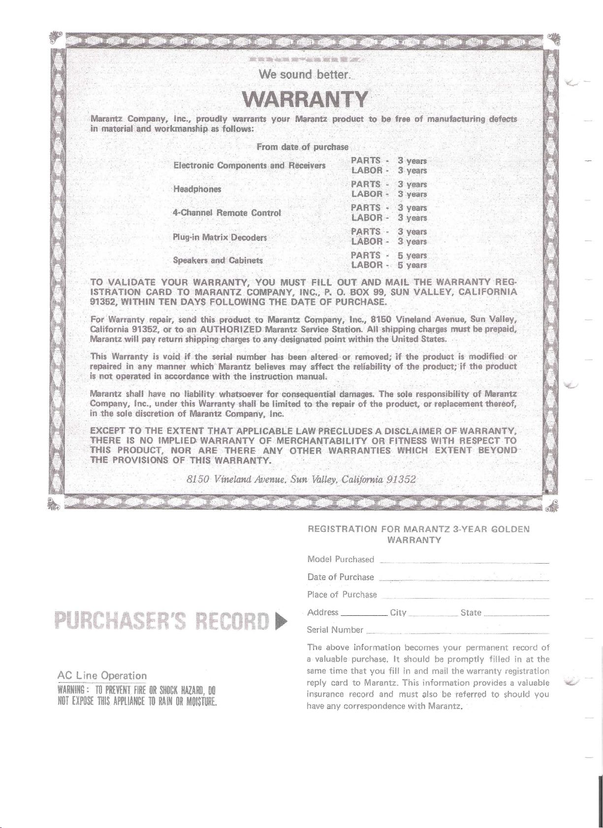
'WARRANTY'
'Marantz: Company. Inc., proudly warrants
inmateriafand
workman,ship
. .
Electronic Components and. Receivers .
·...eadphones
4-Channld-
P1ug~in
SpeakQfS afld Cabinets
as
follows: .
From
Remote Control
Matrix
Dec:oders
YO!-"
.date,
...
Ma
...
of
ntt
product
purchase .
"
to
.befree
PARTS·
LA"
BO'R"
PARTS"
LABOR,
PARTS.
LABOA- .
PARTS'·
LABOR'
PARTS·
LABOR - 5 years
ofmanufaeturing
3
_ years
Syears
3 years
3years
3 years
3 '1ears
3 years
-3
years
5 years
defects
TO VALIDATE YOUR WARRANTY;
ISTRATION CARD TO MARANTZ COMPANY.
91352, WITHIN TEN
F()r'
Warranty repair,
Cillifornia 91352,01'
Marantz·will pay returrishtpPlngehatges
VVarranty
This
repaired in any manne{ whicb Marantz believes may affect
is
not
OPerated in accordance witll
Marantz shall ha'le no liability whatsoever for consequential damages. The sole responsibility
Company, Inc., under this Warranty shall be linlited
in
the sole discretion
EXCEPT
THERE
THIS PRODUCT.
THE
TOTHE
IS
NO
PROVISIONS
DAYS
FOllOWING
send
this produ.ct,to Marantz COmpa"y, lnt:,
to
an AUTHORIZED. Matantz Service Station. AllShipping charges must
is
void if
IMPLIED WARRANTY OF MERCHANTABILITY OR FITNESS
the
serial number has been altered
of
Marantz C()mpariy.
EXTENT THATAPPLICABLE
NOR
ARE THERE
OFTHISWARRAN'tY.
8150
Vineland Avenue,
YOU
MUST
INC.~
THE DATE OF PURCHASE.
toanydeilignatedpoint
theinstruetion
ANY
manual,
InC.
LAW
OTHER WARRANTIES
. .
Sun.
Fill
OUT
AND
P.
O.BOX
within the United States. .
or
removed;
the
reliabitityof
to the repair
t'RECllJOES A DISCLAIMER OF WARRANTY,
Valley,
REGISTRATION FOR
Model Purchased
Calijor'nia
MAIL THE WARRANTY
99,
SUN
VALLEY, CALIFORNIA
8150
Vineland Avenue, Sun Valley,
if
the
prowctk
the
product;
of
the product. or replacement ther.eof,
WHICH
if
WITH
REsPECT .
EXTENT BEYOND'
91352'
MARANTZ
WARRANTY
3-YEAR GOLDEN
REG-
be
prepaid.
modified
the
product
of
Marantz
or
TO
AC
Line Operation
WARNING:
NOT
TO
EXPOSE
THIS
PREVENT
FIRE
APPLIANCE
OR
SHOCK
TO
RAIN
HAZARD,
00
OR
MOISTURE.
of
Date
Place
Address
Serial Number
The above
a valuable purchase.
same
reply card
insurance record and must also
have any correspondence
Purchase
of
Purchase
time
_..--_
~
information
that
you
fill
to
Marantz. This
City
_ _ State _
becomes
It
should
in and mail the warranty registration
information
with
Marafitz.
your
be
promptly
be
permanent record
filled
provides a valuable
referred
to
should you
in
at
of
the
I
FOR
To obtain
from
structions and
carefully.
This manual
covers installation and operation in simple, nontechnical
Model CD-400B in more technical detail.
For quick identification
nections, references
FACE
WORD
optimum
the Model CD-400B,
is
language.
TYPE.
performance and enjoyment
follow
the step-by-step procedures
divided
into
The second describes the
of
to
these
please
the controls
are
study these in-
two
parts. The
printed in BOLD-
and
first
con-
may institute a claim against the carrier
shipping
material
tion. Should
Company
claim.,
Please
Card
Golden Warranty
Marantz Company receives the registration card,
which
CD-400B.
TABLE
damage.
as
fill
as
soon
was
evidence
assistance
will
cooperate
out
and
as
packed
0
Save
the carton and all packing
of
damage
be
fully
mail the Warranty Registration
possible. The Marantz 3-year
will
not
go
in
the carton
C
NTENTS
for
their
required, the Marantz
in
assisting
into
effect until the
with
your
for
inspec-
your
Model
GENERA
Your
operate demodulator
channels from CD-4 records. The Model CD-400B
incorporates
cuit
frequency
carrier level control which selects the
carrier level for the cartridge being
4 records may
400B
CD·400B's controls do
play non-CD-4 records.
played and the MODE pushswitch
4 CH
illuminate
demodulated
AFTER
Marantz Model CD-400B
to
minimize record noise
response,
without
AUTO
and
DESCRIP
for
obtaining
an
Automatic Noise Reduction Cir-
and
an
also
be
played through the
affecting their performance. The
not
have
When
position, the
the record
into
four
RADAR
will
discrete channels.
UNPACKIN
10
is
a simple
four
without
automatic
to
CD·4 records
automatically
affecting
optimum
used.
NoncCD-
be
adjusted
is
indicator
to
discrete
30
kHz
CD-
to
are
in the
will
be
Connecting the CD-400B
Adjustments
Panei
Front
Power Indicator
Power Switch
Selector Switch
Mode Switch
Rear
Panel
CH
2
Phono I
Aux
4
CH
Chassis
Separation Controls
Line Cord
Operation Notes
Functional Description
General Specifications
Service Notes
Repairs
Features
Features
Direct Out Switch and Jacks
nput
Jacks
Input Jacks
Out Jacks
Ground
2
2
4
4
4
4
4
5
5
5
5
5
5
5
5
6
6
8
8
8
It
is
advisable
terial
transport
8
Please'inspect
signs
control and professional pride ensure
CD-400B
the
mediately
shipped
company with'out delay. Only you, the consignee,
for
repacking
of
unit
to
to
to
retain all original packing
prevent
or
ship the Demodulator (refer
shipping
left
is
notify
you directly,
damage
and
shipping instructions),
your
CD-400B carefully
damage.
the factory in perfect condition.
damaged
your dealer.
should'
Our very
or
fails
notify
to
If
the transportation
you wish
to
page
for
strict
quality
that
each
operate, im-
the
unit
ma-
to
any
If
was
LIST
1.
Connection Diagram
2.
Front
3.
Rear
Facilities and Controls
4.
Cartridge Mounting
5.
Functional Block Diagram
6.
Packing Instructions
FilL S
Panel
Switches
Panel
Connection
RATIONS
3
4
5
6
7
8
CONNECTING
Turn
off
the Model CD-400B and any equipment
that
will
be
connected
connections. The CD-400B must
turntable or changer equipped
designed
1.
Connect the turntable or changer
panel
cables recommended
facturer. Using any other cable may seriously
degrade the performance
TURNTABLE/CHANGER
LEFT
RIGHT
GROUNDING
2.
Using standard shielded audio cables
phono plugs make the following connections.
4·CHANNEL
FRONT
FRONT
REAR
REAR
PHONO
PHONO
3.
A discrete 4-channel playback device (0-8
cartridge player, 4-channel discrete reel-to-reel
tape deck, etc.) may
400B using standard shielded audio cables
phono plugs
DISCRETE
PLAYBACK
LEFT
CHANNEL
LEFT
CHANNEL 2 or
for
of
the CD-400B
OUTPUT
OUTPUT
WIRE
AMPLIFIER
CD·4/AUX
CD-4/AUX
CD-4/AUX
CD·4/AUX
IN
LEFT
IN
RIGHT
4-CHANN.El
DEVICE
FRONT
REAR
1
or
or
or
CD-4 records.
L
R
L
R
as
follows:
L F
or
TRACK
L R
or
TRACK
be
1
2
T E
to
it
with
by
of
connected
C.
before making any
be
with
the special audio
the cartridge
the CD·400B.
CD-400B
to
lEFT
to
RIGHT
to
CHASSIS
CD·400B
to 4
CHANNEL
FRONT
to
4 CHANNel
FRONT
to 4 CHANNEL
REAR
to
4 CHANNel
REAR
to
2 CHANNEl
RECT
to
2
CHANNEL
RECT
CD-400B
to
FRONT
to
REAR
-4008
used
a cartridge
to
the rear
PHONO
PHONO
GROUND
l
R
L
R
OUT
OUTRJGHT
to
the CD-
AUX
AUX
with
manu-
with
OUT
OUT
OUT
OUT
DI-
lEFT
01·
with
4.
Set the controls on the 4-channel amplifier in
a
accordance
tions.
5.
Set the CD-400B's
switch
6.
Set the
the PHONO position.
7. Set the rear panel DIRECT
with
to
the 4 CH
front
the manufacturer's instruc-
front
panel MODE push-
AUTO
panel SELECTOR pushswitch
position.
OUT
switch
to
to
OFF.
8.
Connect
providing the AC voltage and frequency specified on
Turn on the turntable,
amplifier.
ADJUSTMENTS
Before the Model CD·400B
ulate CD-4 records, a few simple adjustments
must
The following adjustment procedure should be
performed whenever a new cartridge or stylus
installed.
1.
Decrease
main amplifier
can
2.
Play the CD-4 ADJUSTMENT TONE band
the test record.
3. Adjust the rear panel
CONTROL
left
4.
Play the CD-4 ADJUSTMENT TONE band
the test record.
5.
Adjust the rear panel
CONTROL
rear speaker.
6.
PlaytheCHANNELBALANCE
TONE band
l
l
BALANCE
adjust
four
channel balance.
the
the
rear panel serial number nameplate.
be
made.
the
be
heard.
for
rear speaker.
for
of
CONTROLS
the
relative sound level
channels
AC line cord
front
minimum
to
channel volume on the
so
that
minimum sound
the test record and using
achieve a satisfactory
to
an
AC
CD-40GB
can
only
LEFT
sound level
RIGHT
of
and 4-channel
properly demod-
the rear speakers
SEPARATION
SEPARATION
from
ADJUSTMENT
the main amplifier,
of
each
outlet
of
from
the
of
the right
the
of
the
four
is
'....t
RIGHT
CHANNEL
RIGHT
FRONT
or
3 orTRACK 3
REAR
or
R
R R
For
or
CHANNEL 4 orTRACK
4
tp
FRONT
to
REAR
AUX
AUX
R
R
NOTE: The CD-400B contains a special
to
control
detector and thereby optimize its per·
formance. No adjustments
level (band
the
lock
range
of
2
of
the supplied test record)
the carrier
for
circuit
carrier
-.t
--
 Loading...