

Page 1
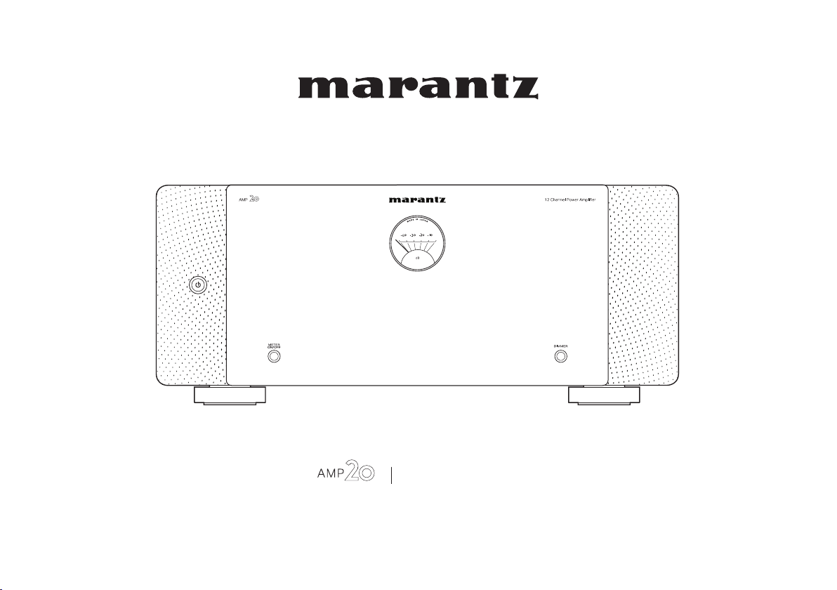
Power Amplifier
Owner’s Manual
1
Page 2
Contents Connections Playback Tips Appendix Specifications
Accessories
Features
High quality sound
High performance
Part names and functions
Front panel
Rear panel
4
Connections
5
Preparations
5
Speakers
5
Preamplifier
6
Example connection variation
6
Connecting a Preamplifier
8
Example of connections to Marantz AV 20 Preamplifier
Bi-amp connection
BTL connection
Connecting an external control device
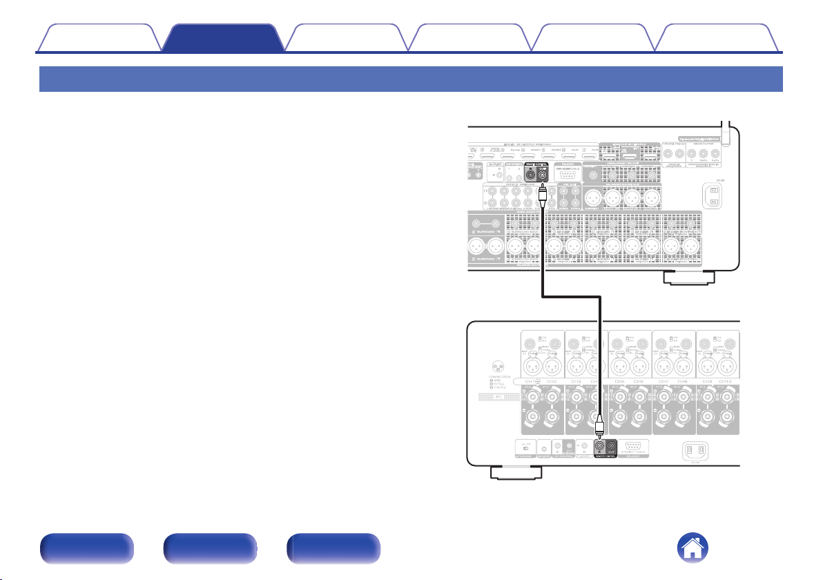
AMP CONTROL jacks
REMOTE CONTROL jacks
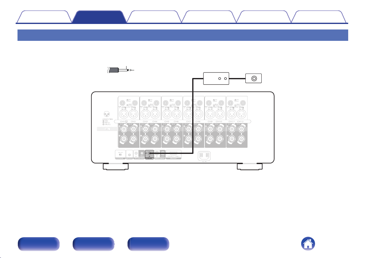
FLASHER IN jack
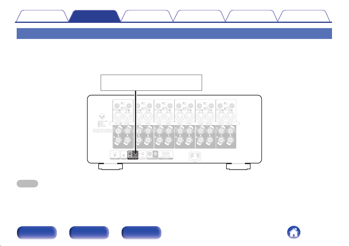
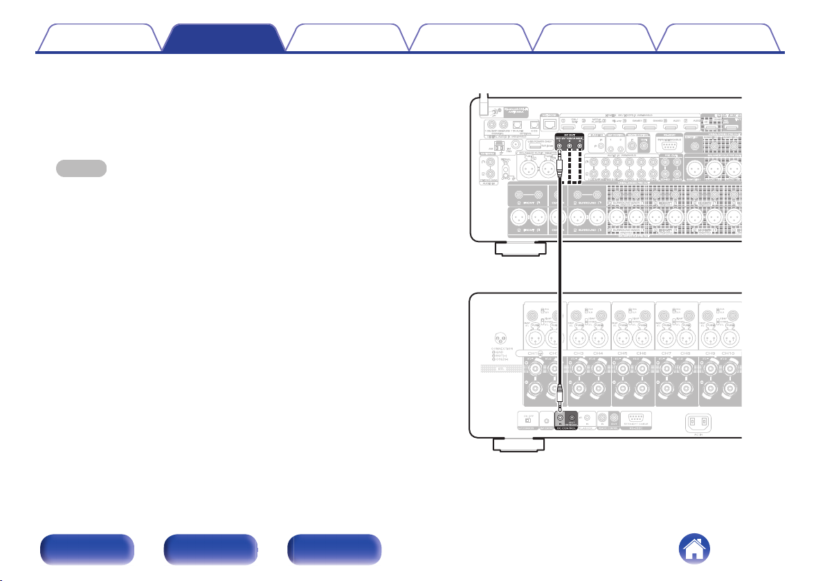
DC CONTROL jacks
Setting the auto standby function
Connecting the power cord
12
12
14
15
16
16
18
19
20
20
21
22
23
25
26
Front panel Rear panel Index
2
Page 3
Contents Connections Playback Tips Appendix Specifications
Playback
Basic operation
Turning the power on
Turning the power standby
Turning the level meter display on or off
Changing the brightness of the illumination
Tips
28
Troubleshooting
28
28
29
30
Power does not turn on / Power is turned off
No sound comes out
Resetting to the default values
Appendix
Explanation of terms
Specifications
Specifications
Index
31
32
33
34
35
36
38
Front panel Rear panel Index
3
Page 4
Remote control
connector cable
Safety InstructionsQuick Start Guide
AMP control
connector cable
Speaker terminal wrench
Power cord
Contents Connections Playback Tips Appendix Specifications
Thank you for purchasing this Marantz product.
To ensure proper operation, please read this owner’s manual carefully before using the product.
After reading this manual, be sure to keep it for future reference.
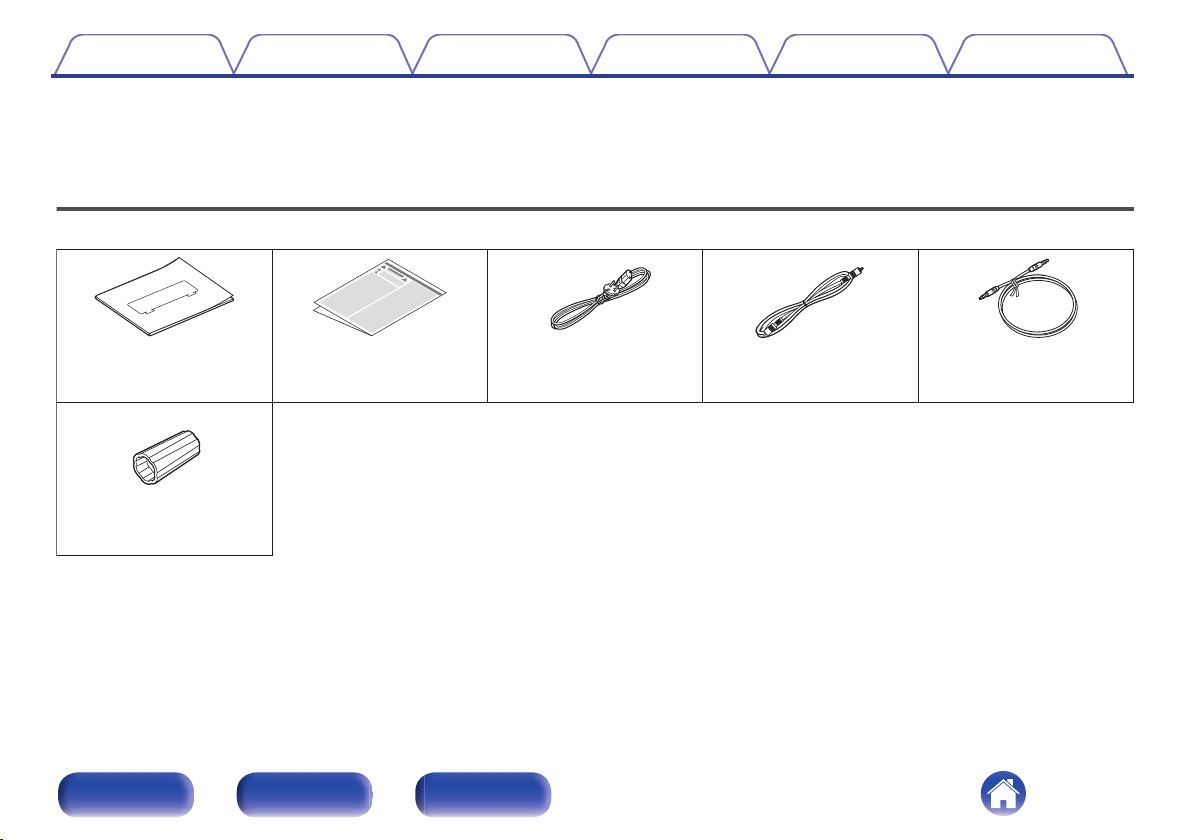
Accessories
Check that the following parts are supplied with the product.
Front panel Rear panel Index
4
Page 5
Contents
Features
Connections Playback Tips Appendix Specifications
High quality sound
12-channel switching power amplifier module
0
A switching power amplifier is used to achieve a high output of 200W
per channel (8Ω, 1kHz, T.H.D.: 0.05%, 2-channel operation). To ensure
excellent performance, minimal distortion occurs across all frequencies.
Additionally, there is little change in frequency characteristics due to
speaker impedance. This system is combined with a high-speed
preamplifier circuit with an HDAM for accurate reproduction of the fine
nuances of DSD and high-resolution audio sources.
Current feedback amplifier
0
This unit has a high-speed current feedback amplifier circuit for
accurate amplification of signals from HD audio devices such as Blu-ray
disc players. The high-speed current feedback amplifier also achieves
natural sound field reproduction.
High audio quality parts
0
Each part of the circuit is designed to ensure high audio quality,
including high audio quality MELF resistance and an electrolytic
capacitor.
Double-layered chassis
0
High-end machined brass speaker jacks
0
High performance
Switch between UNBALANCED RCA and BALANCED XLR
0
You can choose between two input channels: UNBALANCED RCA
input or BALANCED XLR input.
BI-AMP/BTL connection setting function
0
You can set a bi-amp connection and BTL connection for the power
amplifier of each of the two channels without needing to connect an
additional cable from the preamplifier.
The BI-AMP connection prevents interference from counterelectromotive force as the woofer and tweeter are powered by separate
power amplifiers. The BTL (Bridge) connection achieves a high drive
performance as the positive and negative terminals of the speakers are
directly powered according to the output levels of the power amplifier.
Additionally, the drive current of the speakers does not directly enter the
ground circuit. This stabilizes the ground potential that the amplitude is
based on, reducing noise and interference between circuits to achieve
an accurate amplitude.
AMP CONTROL function
0
By connecting this unit to a Marantz AV Preamplifier with an AMP
CONTROL jack using the included cable, you can control operation of
both units simultaneously, such as controlling the power or the
illumination display settings. The connection to the AV Preamplifier is a
ground floating connection that does not create an earth loop,
minimizing adverse impacts on audio quality.
Other Functions
0
Equipped with IR flash input that supports custom installations, and DC
trigger input and output terminals.
Front panel Rear panel Index
5
Page 6
q rw we yt
Contents
Connections Playback Tips Appendix Specifications
Part names and functions
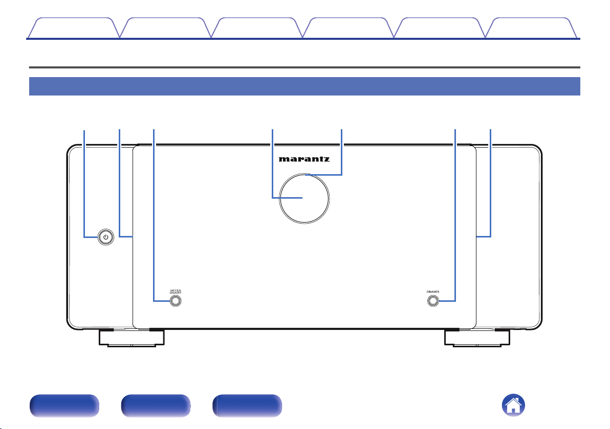
Front panel
For details, see the next page.
Front panel Rear panel Index
6
Page 7
w we t yq r
Contents Connections Playback Tips Appendix Specifications
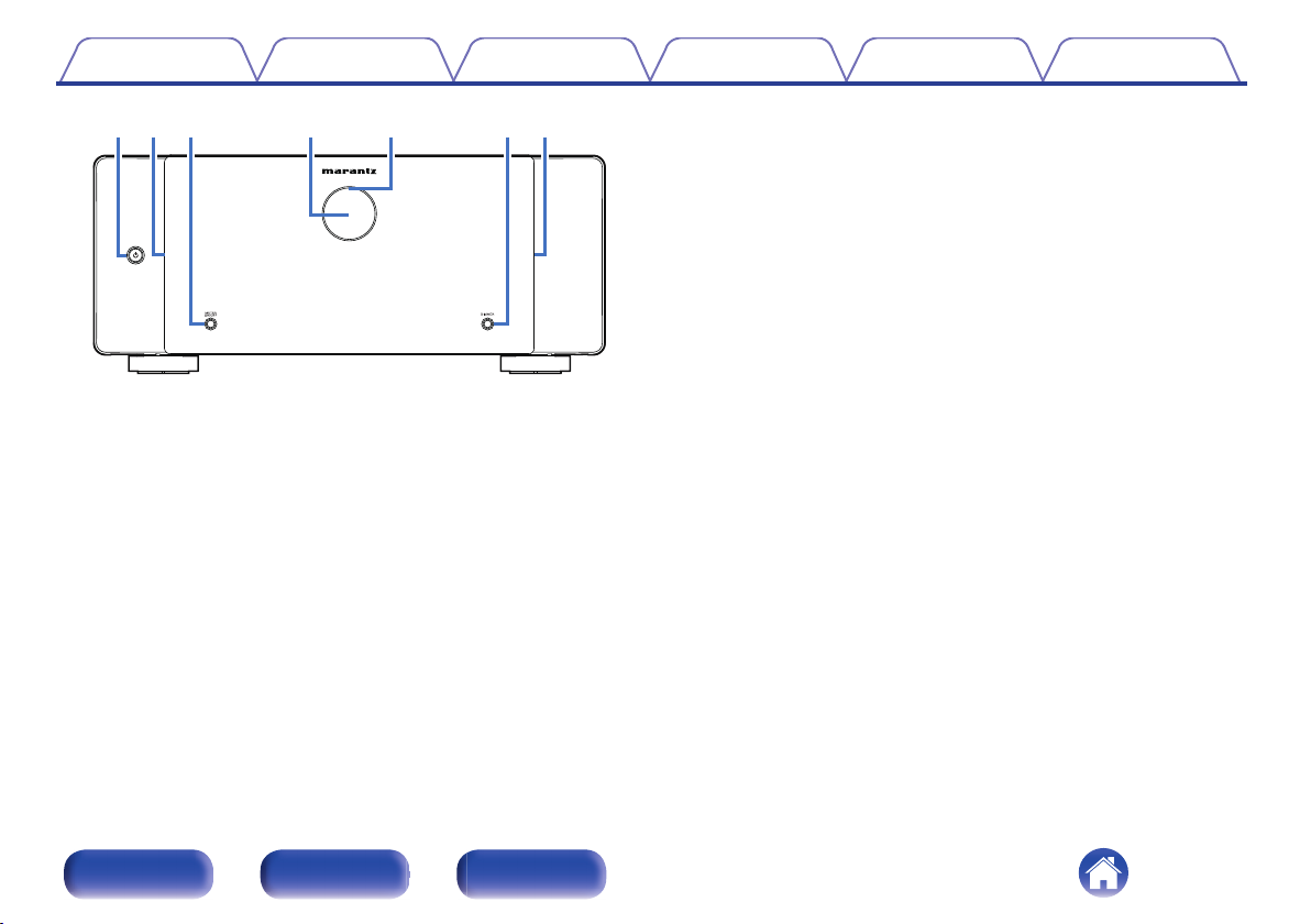
METER ON/OFF button
C
Turns the level meter display and meter lighting on or off. (v p. 29)
Level meter
D
Displays the level of the signal input through channel 1. This can be
turned off by pressing METER ON/OFF.
Protection circuit indicator
E
This blinks when the protection circuit has operated. (v p. 32)
DIMMER button
F
Press this button to change the brightness of the illumination.
(v p. 30)
Power operation button (X)
A
Used to turn the power on/off (standby). (v p. 28)
Illumination
B
Lit when the power is turned on. The brightness of the illumination can
be changed by pressing DIMMER.
Front panel Rear panel Index
7
Page 8
w
q
e
ytuioQ0 Q1r
Q2
Contents
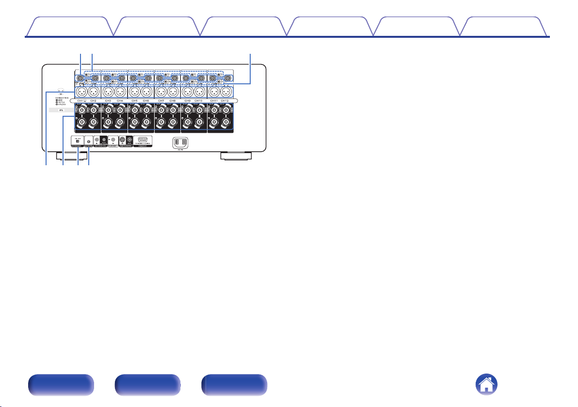
Rear panel
Connections Playback Tips Appendix Specifications
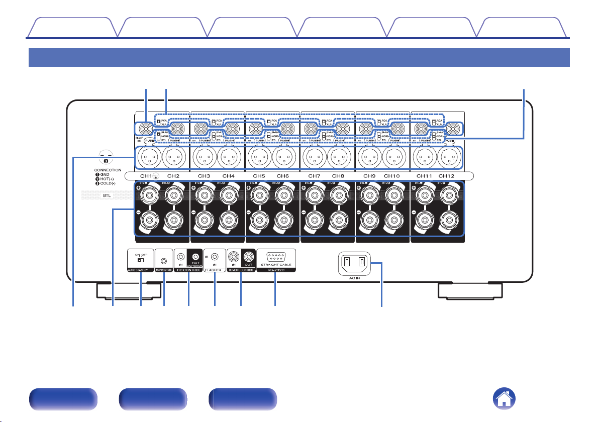
For details, see the next page.
Front panel Rear panel Index
8
Page 9
q
ryut
we
Contents
UNBALANCED RCA INPUT connectors
A
Used to connect a preamplifier with UNBALANCED RCA output
connectors.
RCA/XLR INPUT selector
B
Switches according to the jack used for connecting to the preamplifier
(UNBALANCED RCA or BALANCED XLR).
NORMAL/BI-AMP/BTL selector
C
You can set a bi-amp connection and BTL connection for the power
amplifier of each of the two channels.
Connections Playback Tips Appendix Specifications
BALANCED XLR INPUT connectors
D
Used to connect a preamplifier with BALANCED XLR output
connectors.
Speaker terminals (SPEAKERS)
E
Used to connect speakers. (v p. 16)
AUTO STANDBY selector
F
When the auto standby function is set to “ON”, the power of this unit
automatically enters standby after 15 minutes of no input signal and no
operations. (v p. 25)
AMP CONTROL jacks
G
Use these to connect to a Marantz preamplifier with AMP CONTROL
jacks. This enables operations to be performed simultaneously on this
unit and the preamplifier, such as turning the power on or placing it on
standby and adjusting the brightness of the illumination. (v p. 20)
Front panel Rear panel Index
9
Page 10
ioQ0 Q1 Q2
Contents Connections Playback Tips Appendix Specifications
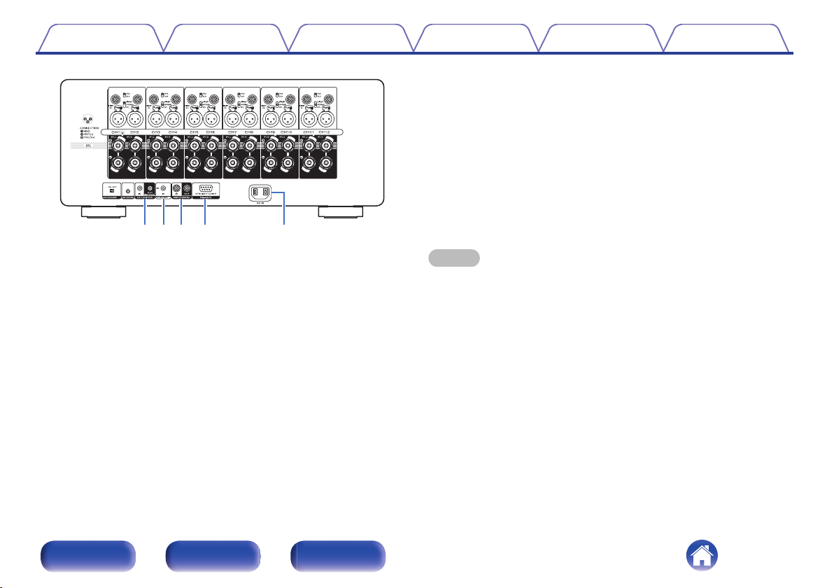
RS-232C connector
K
Used to connect home automation controller devices fitted with
RS-232C connectors. Consult the owner’s manual of the home
automation controller for more information about serial control of this
unit.
Perform the operation below beforehand.
Turn on the power of this unit.
A
Turn off the power of this unit from the external controller.
B
Check that the unit is in the standby mode.
C
AC inlet (AC IN)
L
Used to connect the power cord. (v p. 26)
DC CONTROL jacks
H
Used to connect devices equipped with the trigger function.
(v p. 23)
FLASHER IN jack
I
Used to connect commercially available (sold separately) IR repeaters.
(v p. 22)
REMOTE CONTROL jacks
J
Used to connect a Marantz product that is equipped with REMOTE
CONTROL terminals. Use this when you want to control this unit with a
remote control. (v p. 21)
Front panel Rear panel Index
NOTE
Do not touch the inner pins of the connectors on the rear panel. Electrostatic
0
discharge may cause permanent damage to the unit.
10
Page 11
R
L
R
L
Contents Connections Playback Tips Appendix Specifications
o
Contents
Preparations 12
Example connection variation 15
Connecting a Preamplifier 16
Connecting an external control device 20
Setting the auto standby function 25
Connecting the power cord 26
NOTE
Do not plug in the power cord until all connections have been completed.
0
Do not bundle power cords together with connection cables. Doing so can result in
0
noise.
o
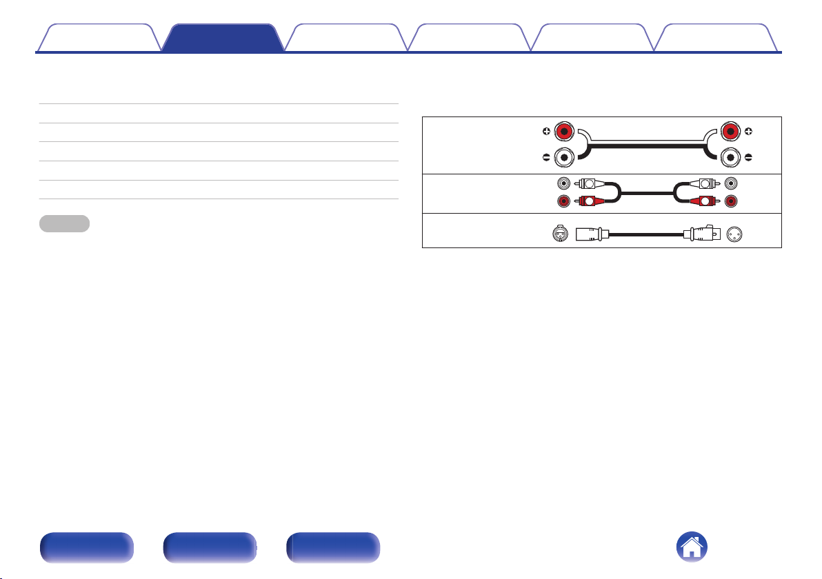
Cables used for connections
Provide necessary cables according to the devices you want to
connect.
Speaker cable
Audio cable
XLR cable
Front panel Rear panel Index
11
Page 12
Contents Connections Playback Tips Appendix Specifications
Preparations
Speakers
This section explains how to connect them using typical examples.
NOTE
Disconnect this unit’s power plug from the power outlet before connecting the
0
speakers.
Connect so that the speaker cable core wires do not protrude from the speaker
0
terminal. The protection circuit may be activated if the core wires touch the rear
panel or if the + and - sides touch each other. (“Protection circuit” (v p. 35))
Never touch the speaker terminals while the power supply is connected. Doing so
0
could result in electric shock.
Use speakers with an impedance of 4 – 16 Ω/ohms.
0
o
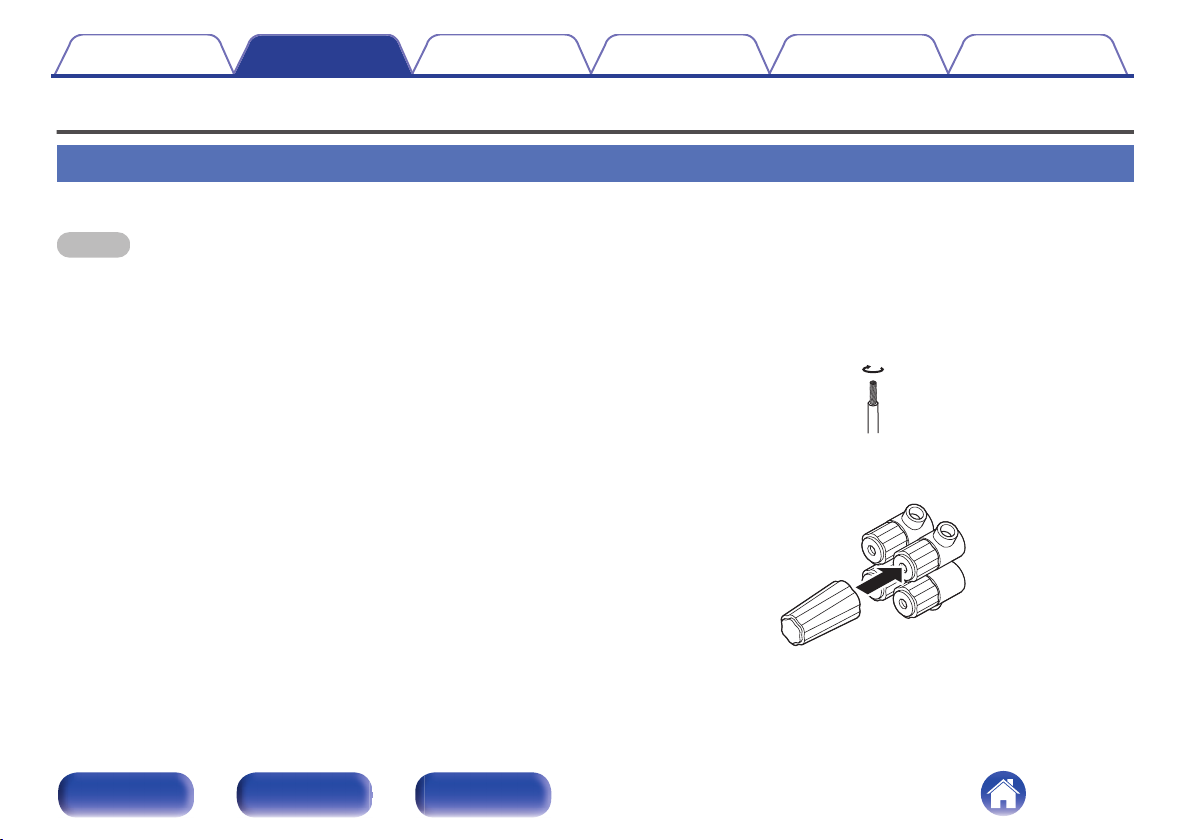
Connecting the speaker cables
Carefully check the left (L) and right (R) channels and + (red) and –
(black) polarities on the speakers being connected to this unit, and be
sure to connect the channels and polarities correctly.
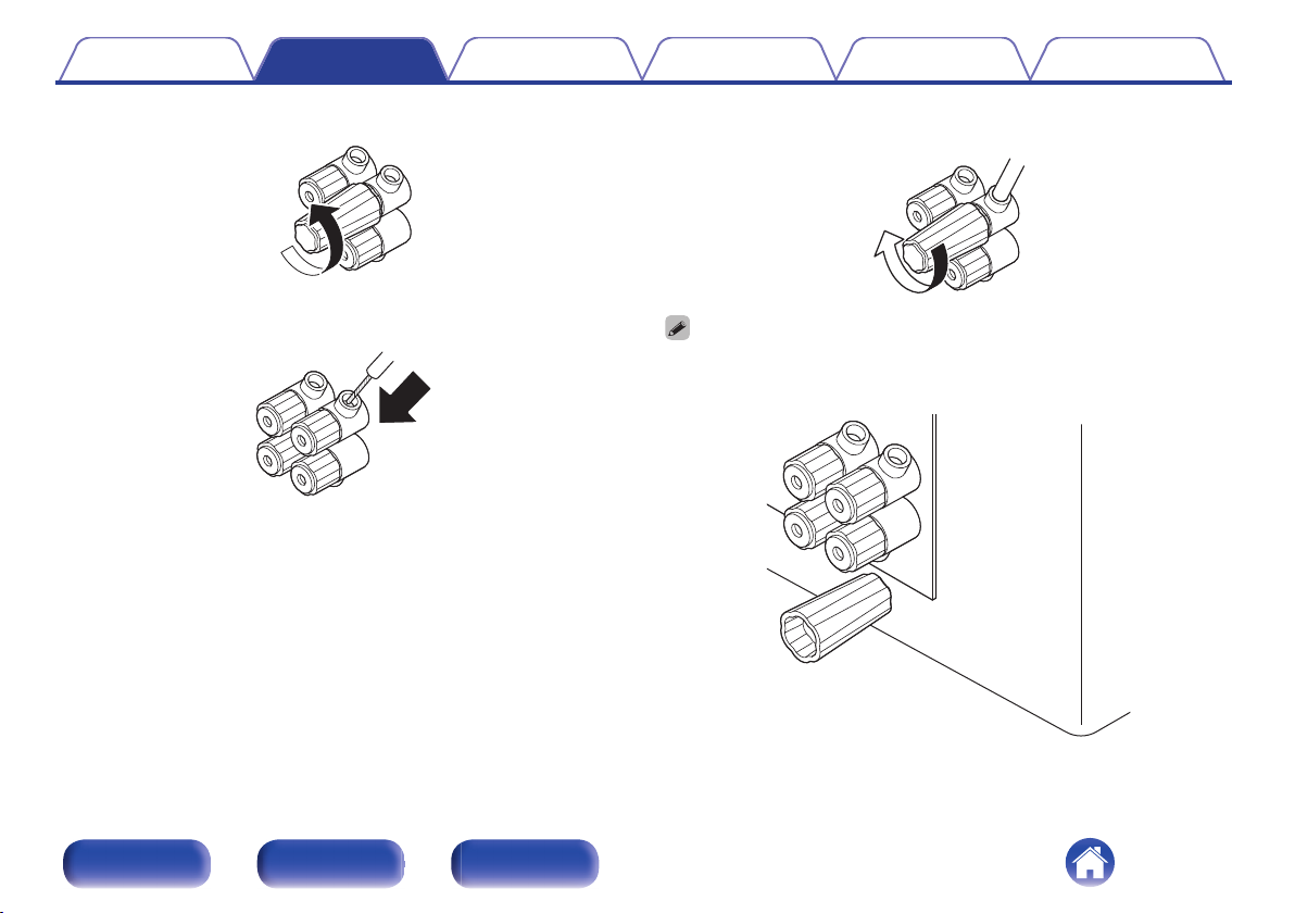
Peel off about 15 mm of sheathing from the tip of the
1
speaker cable, then either twist the core wire tightly or
terminate it.
Attach the included speaker terminal wrench to the
2
speaker terminal.
Front panel Rear panel Index
12
Page 13
Contents Connections Playback Tips Appendix Specifications
Turn the speaker terminal counterclockwise to loosen it.
3
Insert the speaker cable’s core wire to the hilt into the
4
speaker terminal.
Turn the speaker terminal clockwise to tighten it.
5
The speaker terminal wrench contains a built-in magnet that enables it to be
0
attached to the rear panel. After connecting speakers, store it in the included
accessory box or in another safe place.
Front panel Rear panel Index
13
Page 14
ew q
Contents
Connections Playback Tips Appendix Specifications
Preamplifier
Connect one end of the cable to the input terminals of this unit and the
0
other end to the output terminals of the preamplifier (sold separately).
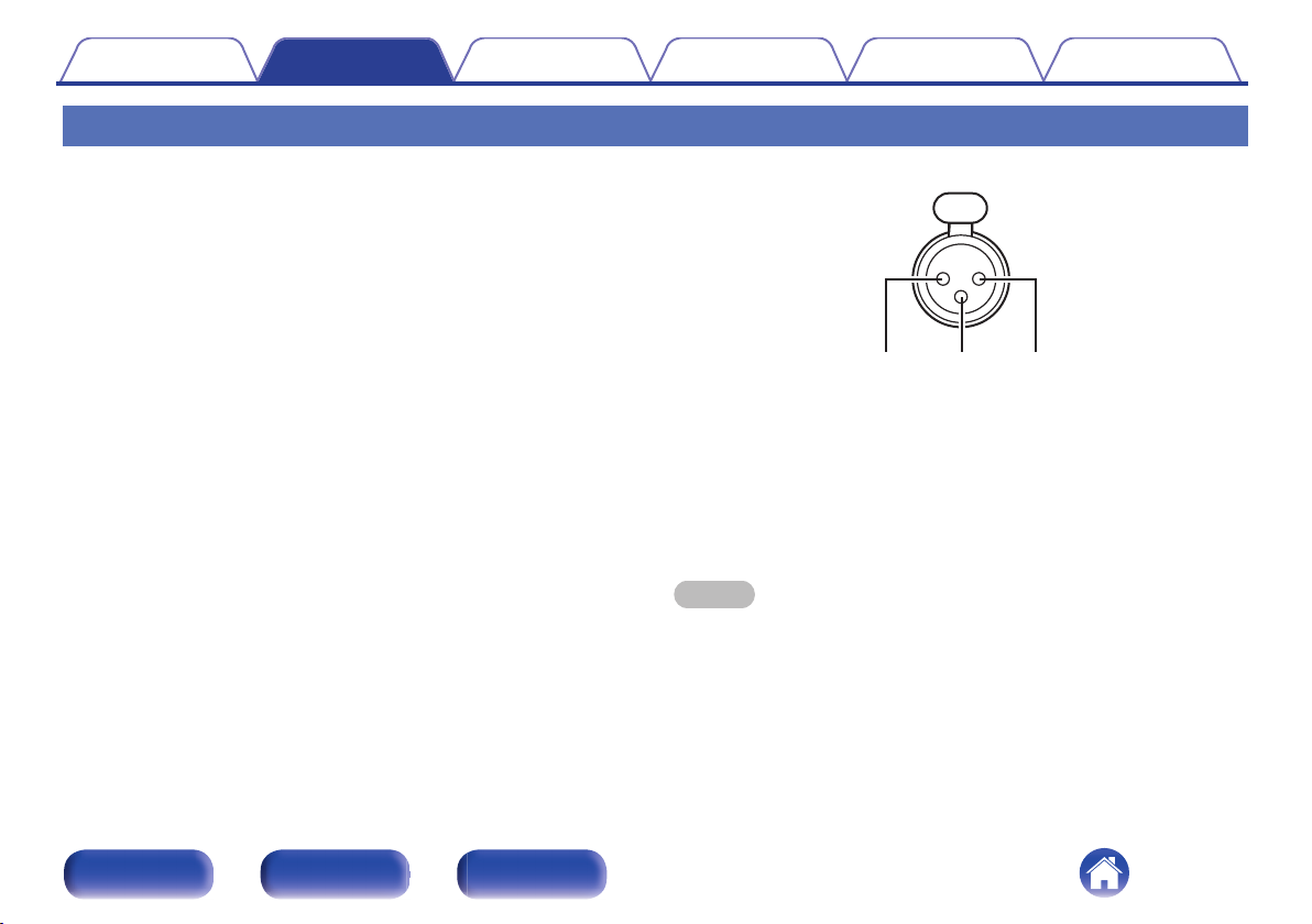
This unit has UNBALANCED RCA connectors and BALANCED XLR
0
connectors. Select the appropriate connectors for the preamplifier you
will use and change the setting of the RCA or XLR selector on this unit.
If the preamplifier has both types of connectors, either type can be
used.
GXLR connector PIN arrangementH
GND (Ground)
A
HOT (Hot)
B
COLD (Cold)
C
The PIN arrangement in this unit uses the European method.
In the USA method, B is COLD, and C is HOT.
When connecting a device that utilizes the USA type of PIN arrangement,
replace the B and C plugs on one side of the balanced cable.
NOTE
Do not short the HOT and GND or COLD and GND for use.
0
Remove the power plug of this unit from the outlet before connecting the
0
preamplifier. Turn off the power of the device being connected as well.
Front panel Rear panel Index
14
Page 15
FL
SW
SWSW
SW SWSWSW
FR SL SR SBL SBRC
FL FR SL SR SBL SBRC
FHL FHR
RHL RHR
TML TMR
FL FR SL SR SBL SBRC
CH TS
Z2L Z2R Z3L Z3R
FHL FHR
RHL RHR
FL
FR
C
SL
SW
SBL
SBR
FHL
FHR
RHL
TMR
CH
TS Z2L Z2R
Z3L
Z3R
RHR
SR
TML
This unit
This unit This unit
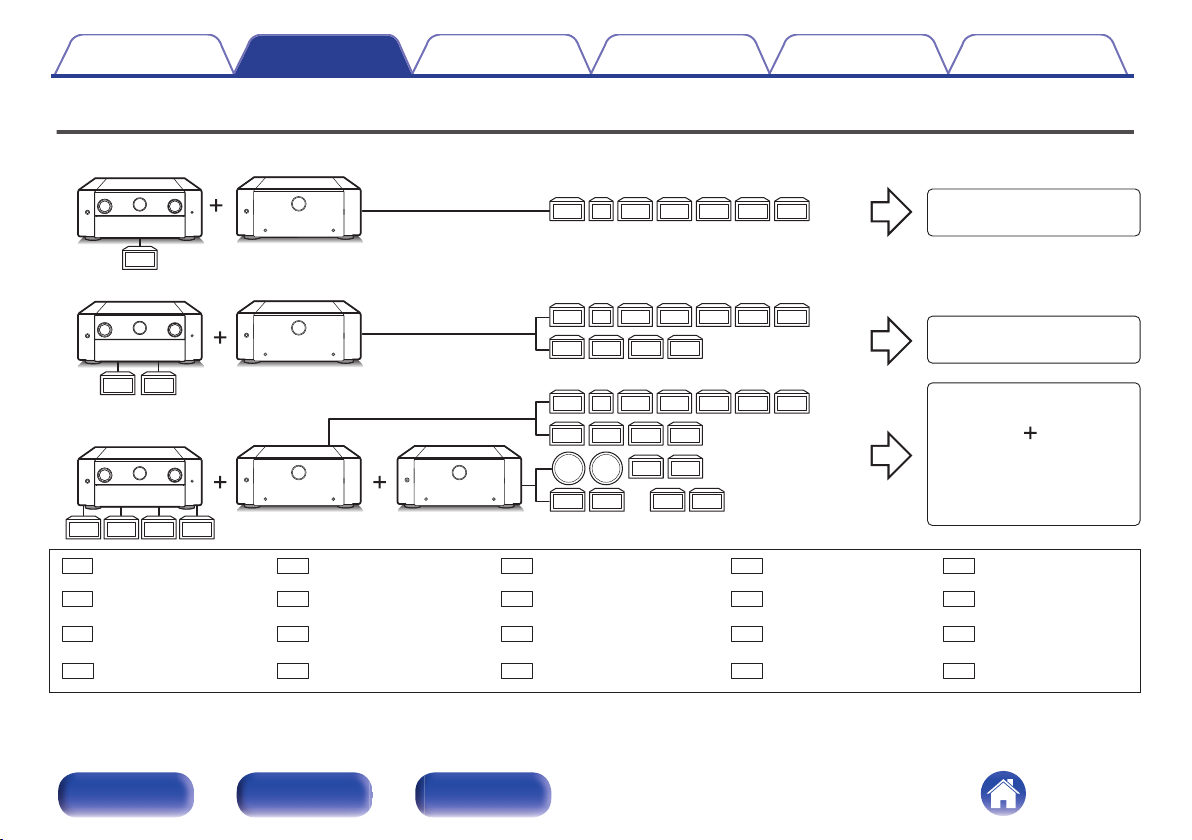
7.1ch connection
11.2ch Configuration
15.4ch Configuration
ZONE2 connection
or
ZONE3 connection
This unit[Example 1] AV 20
[Example 2] AV 20
[Example 3] AV 20
Front speaker (L) Front speaker (R) Center speaker Surround speaker (L)
Subwoofer Surround back speaker (L) Surround back speaker (R)
Front height speaker (L)
Front height speaker (R)
Rear height speaker (L)
Top middle speaker (R)
Center height speaker
Top surround speaker ZONE2 speaker (L) ZONE2 speaker (R)
ZONE3 speaker (L)
ZONE3 speaker (R)
Rear height speaker (R)
Surround speaker (R)
Top middle speaker (L)
Contents Connections Playback Tips Appendix Specifications
Example connection variation
Front panel Rear panel Index
15
Page 16
SR SLFR FL C TMR TML CH TS
RHR RHL
FHR FHL
SBLSBR
Marantz
AV 20
Marantz
AMP 20
Marantz
AMP 20
Second unit
Contents
Connections Playback Tips Appendix Specifications
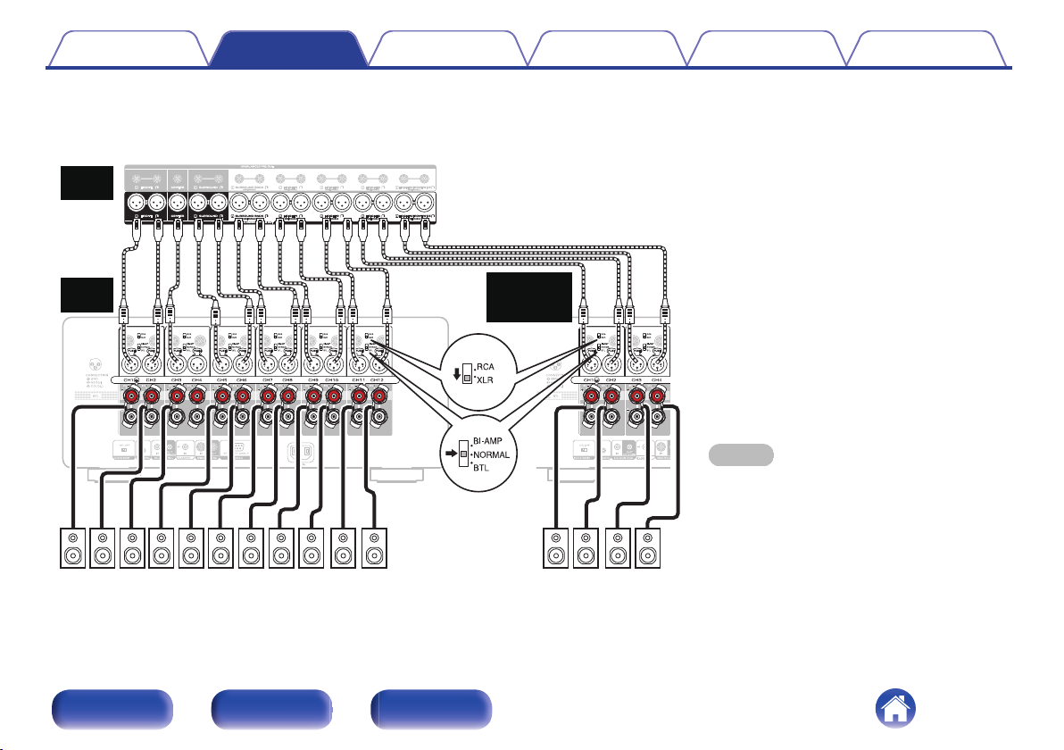
Connecting a Preamplifier
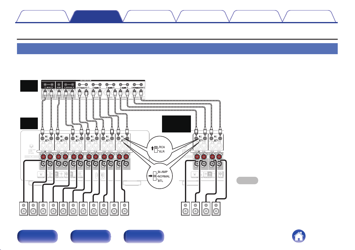
Example of connections to Marantz AV 20 Preamplifier
Connecting the UNBALANCED RCA PRE OUT connector
o
If using the UNBALANCED RCA connectors, switch the RCA/XLR INPUT selector setting to “RCA”. Set the NORMAL/BI-AMP/BTL selector to
“NORMAL”.
Front panel Rear panel Index
16
NOTE
Be sure to configure the RCA/XLR INPUT selector
0
and NORMAL/BI-AMP/BTL selector settings before
turning the power on. If you try to change these
settings after turning the power on, the settings will
not change.
Page 17
SR SLFR FL C RHR RHLFHR FHL
SBLSBR
TMR TML CH TS
Marantz
AV 20
Marantz
AMP 20
Marantz
AMP 20
Second unit
Contents
Connecting the BALANCED XLR PRE OUT connector
o
Connections Playback Tips Appendix Specifications
If using the BALANCED XLR connectors, switch the RCA/XLR INPUT selector setting of this unit to “XLR”. Set the NORMAL/BI-AMP/BTL selector to
“NORMAL”.
Front panel Rear panel Index
17
NOTE
Be sure to configure the RCA/XLR INPUT selector
0
and NORMAL/BI-AMP/BTL selector settings before
turning the power on. If you try to change these
settings after turning the power on, the settings will
not change.
Page 18
wq
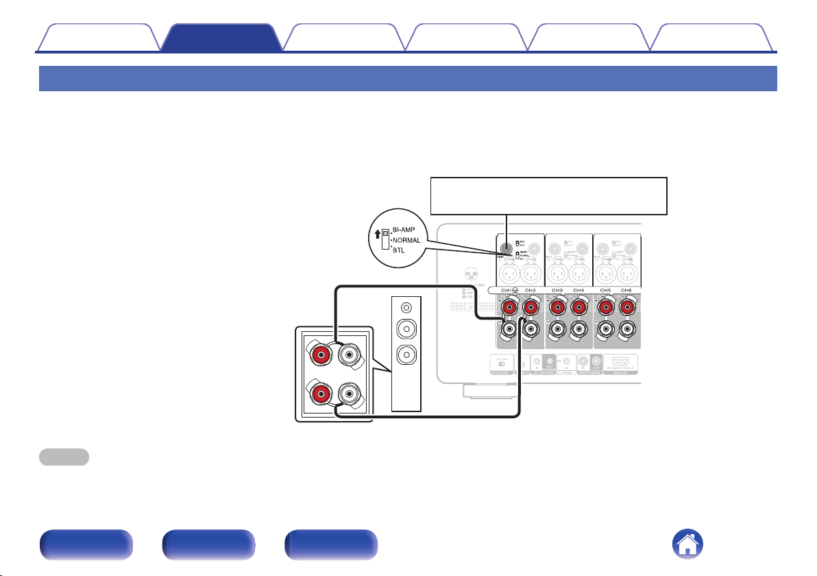
Switch the NORMAL/BI-AMP/BTL selector
setting to BI-AMP.
Connect one cable from
channel 1 to the tweeter of the
speaker and the other cable
from channel 2 to the woofer of
the speaker.
Input to the odd-numbered channel (channel 1).
Contents
Connections Playback Tips Appendix Specifications
Bi-amp connection
Bi-amp connection is a method to connect separate amplifiers to the tweeter terminal and woofer terminal of a speaker that supports bi-amplification. This
connection enables back EMF (power returned without being output) from the woofer to flow into the tweeter without affecting the sound quality, producing
a higher sound quality.
Example: Using channels 1 and 2 as a bi-amp
NOTE
When making bi-amp connections, be sure to remove the short-circuiting plate or wire between the speaker’s woofer and tweeter terminals.
0
Be sure to configure the and NORMAL/BI-AMP/BTL selector setting before turning the power on. If you try to change these settings after turning the power on, the settings
0
will not be applied.
Front panel Rear panel Index
18
Page 19
wq
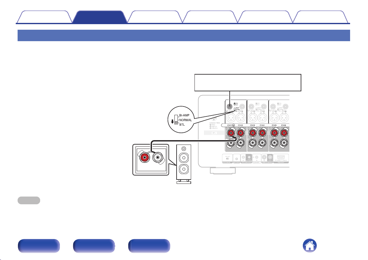
Input to the odd-numbered channel (channel 1).
Switch the NORMAL/BI-AMP/BTL
selector setting to BTL.
Connect one cable from the
positive (+) side of channel 1 to
the negative (-) side of the
speaker and the other cable from
the positive side of channel 2 to
the positive side of the speaker.
Contents Connections Playback Tips Appendix Specifications
BTL connection
A BTL connection uses two channels to power one speaker. Two power amplifiers are used to output antiphase signals from one input signal, achieving
powerful audio reproduction.
Example: Using channels 1 and 2 for a BTL connection
NOTE
Be sure to configure the and NORMAL/BI-AMP/BTL selector setting before turning the power on. If you try to change these settings after turning the power on, the settings
0
will not be applied.
Front panel Rear panel Index
19
Page 20
This unit
[Example] AV 20
Contents Connections Playback Tips Appendix Specifications
Connecting an external control device
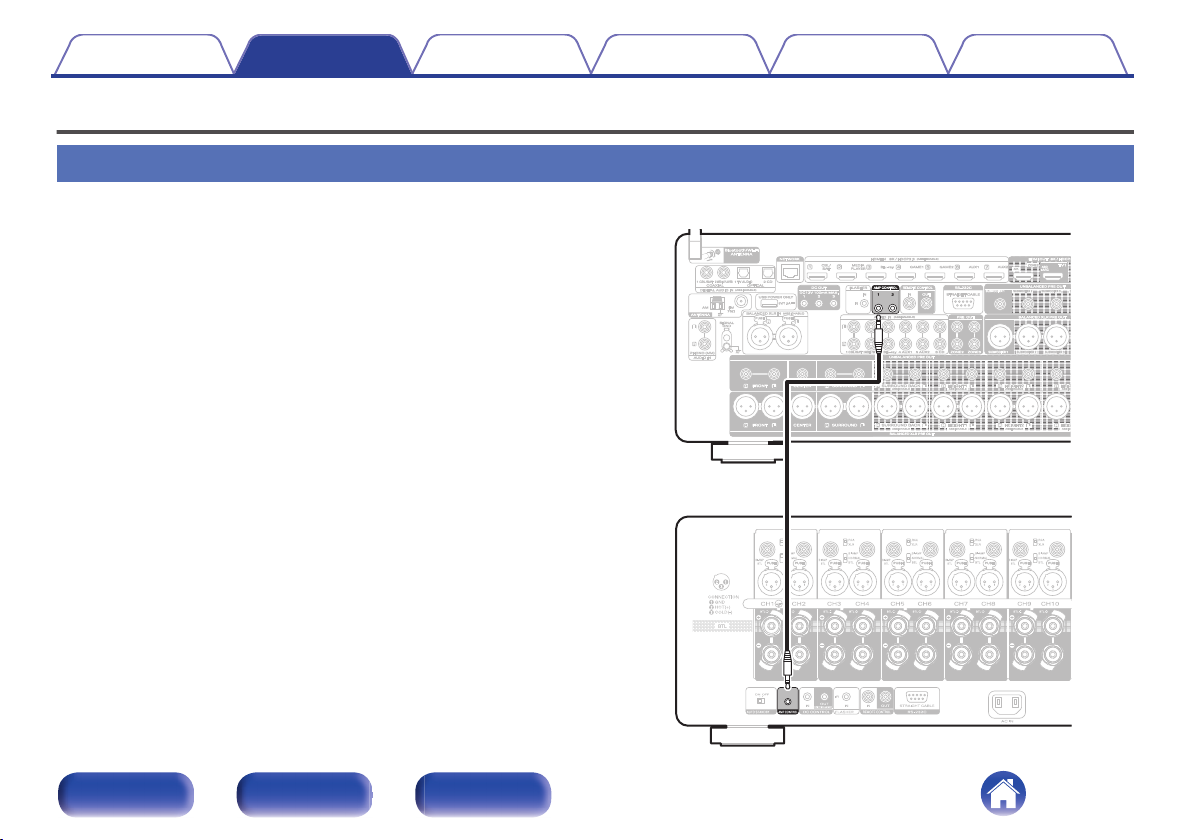
AMP CONTROL jacks
You can connect this unit to a Marantz AV Preamplifier with an AMP
CONTROL jack using the included control cable and perform the following
operations for both units simultaneously.
When the power of the preamplifier is turned on or placed on standby,
0
the power of this unit is turned on or placed on standby too.
When the brightness of the preamplifier’s display is adjusted, the same
0
setting is applied to the illumination of this unit
Front panel Rear panel Index
20
Page 21
This unit
[Example] AV 20
Contents Connections Playback Tips Appendix Specifications
REMOTE CONTROL jacks
When connecting a Marantz AV Preamplifier, you can switch the power of
this unit to ON/STANDBY together with the AV Preamplifier power supply.
For details, see the AV Preamplifier owner’s manual.
Front panel Rear panel Index
21
Page 22
GND
Signal
Monaural mini-plug cable
(Sold separately)
IR repeater IR receiver
Contents Connections Playback Tips Appendix Specifications
FLASHER IN jack
If a commercially available (sold separately) IR repeater is connected to the FLASHER IN jack of this unit, remote control operations can be performed
even if this unit is installed in a place where the remote control signal may not reach, such as in a cabinet.
Front panel Rear panel Index
22
Page 23
12 V DC/150 mA trigger-compatible device
Contents
Connections Playback Tips Appendix Specifications
DC CONTROL jacks
DC CONTROL OUT jack
o
When a device with DC CONTROL IN jack is connected, the connected device’s power on/standby can be controlled through linked operation to this
unit.
The DC CONTROL OUT jack outputs a maximum 12 V DC/150 mA electrical signal.
NOTE
Use a monaural mini-plug cable for connecting the DC OUT jacks. Do not use a stereo mini-plug cable.
0
If the permissible trigger input level for the connected device is larger than 12 V DC/150 mA, or has shorted, the DC OUT jack cannot be used. In this case, turn off the power
0
to the unit, and disconnect it.
Front panel Rear panel Index
23
Page 24
This unit
[Example] AV 20
Contents Connections Playback Tips Appendix Specifications
o
DC CONTROL IN jack
Used when connecting a unit that has a DC CONTROL OUT jack to
this device, and linking the power ON/STANDBY of the connected
device with the power ON/STANDBY of this unit.
For details, see the instruction manual of the connected device.
NOTE
When a 5 V – 15 V voltage is input to the DC CONTROL IN jack, the power of
0
this unit switches ON.
However, inputting voltage outside of this range will cause damage to this unit.
Front panel Rear panel Index
24
Page 25
Contents
Connections Playback Tips Appendix Specifications
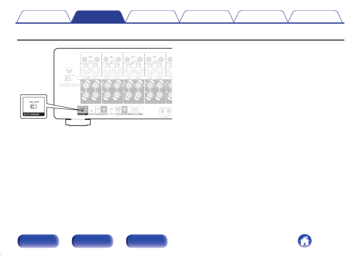
Setting the auto standby function
When the auto standby function is set to “ON”, the power of this unit
automatically enters standby after 15 minutes of no input signal and no
operations.
To use the auto standby function, set the AUTO STANDBY selector to
“ON”.
The factory setting is “ON”.
Front panel Rear panel Index
25
Page 26
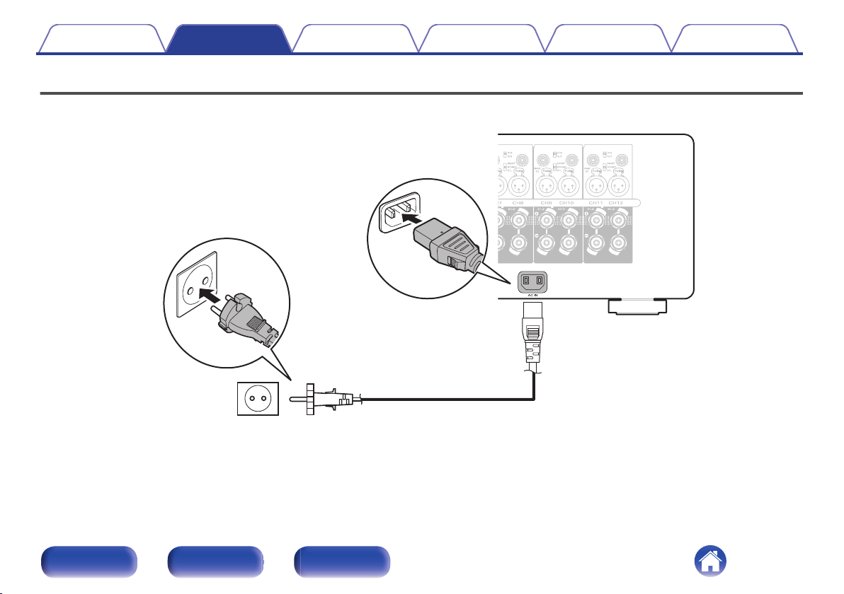
(AC 230 V, 50/60 Hz)
To household power outlet
Power cord (supplied)
Contents Connections Playback Tips Appendix Specifications
Connecting the power cord
After completing all the connections, insert the power plug into the power outlet.
Front panel Rear panel Index
26
Page 27
Contents Connections Playback Tips Appendix Specifications
o
Contents
Basic operation
Turning the power on 28
Turning the power standby 28
Convenience functions
Turning the meter display off 29
Changing the brightness of the illumination 30
Front panel Rear panel Index
27
Page 28
X
Illumination Illumination
Level meter
Contents Connections Playback Tips Appendix Specifications
Basic operation
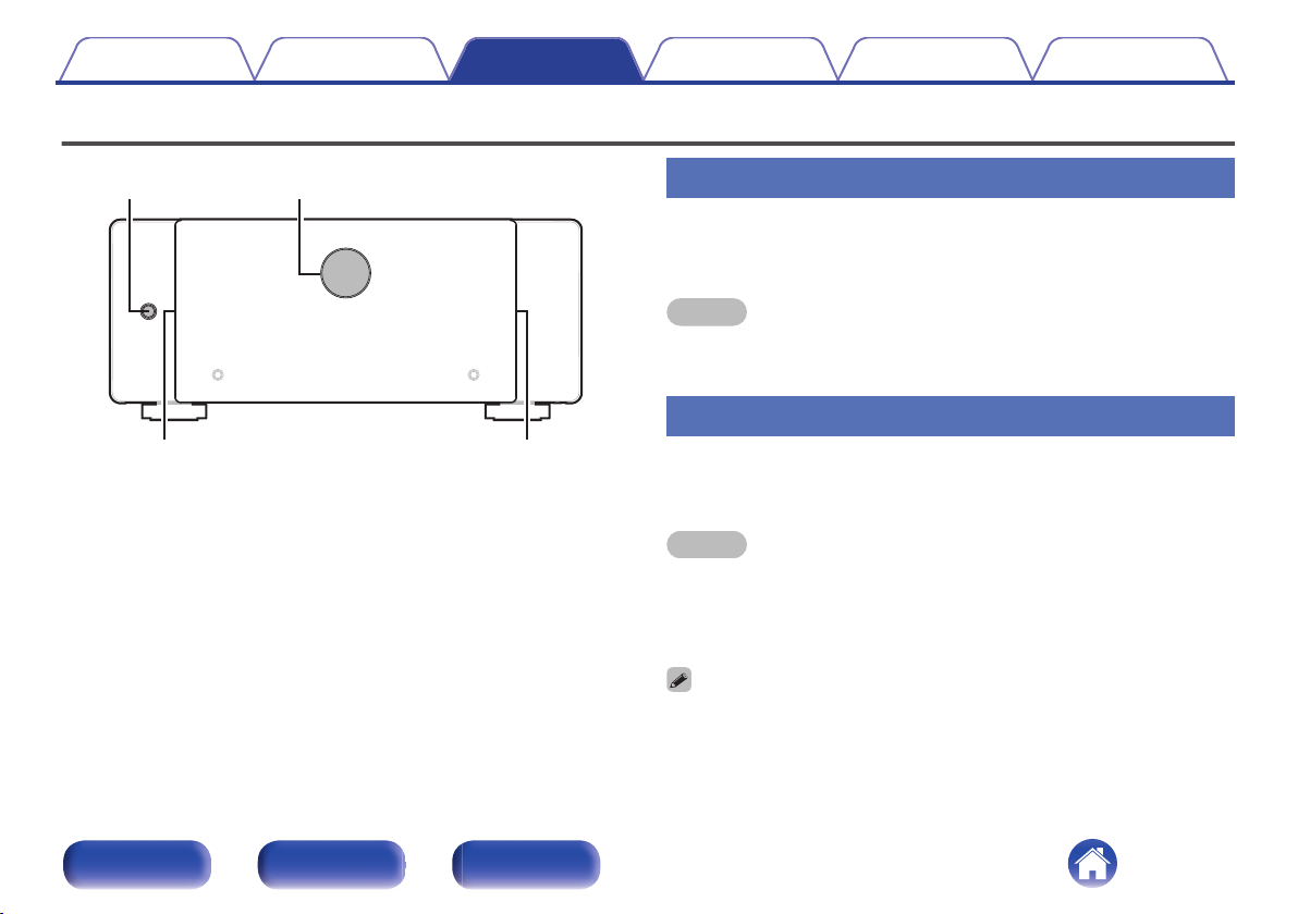
Turning the power on
Press X to turn on power to the unit.
1
The level meter and illumination are lit.
NOTE
When turning the power ON, turn the volume control of connected devices down to
0
the minimum.
Turning the power standby
Press X.
1
The unit switches to standby mode.
NOTE
Even if the unit is switched to standby, some of the circuits are still active. If you
0
will not be using this unit for a prolonged period (due to a holiday etc), remove the
power plug from the wall socket.
Furthermore, to prevent unexpected accidents, make sure the power plug is
located where it can be removed at any time.
Front panel Rear panel Index
You can connect this unit to a Marantz AV Preamplifier with an AMP CONTROL
0
jack using the included cable and perform operations for both units
simultaneously, such as turning the power on or off. (v p. 20)
28
Page 29
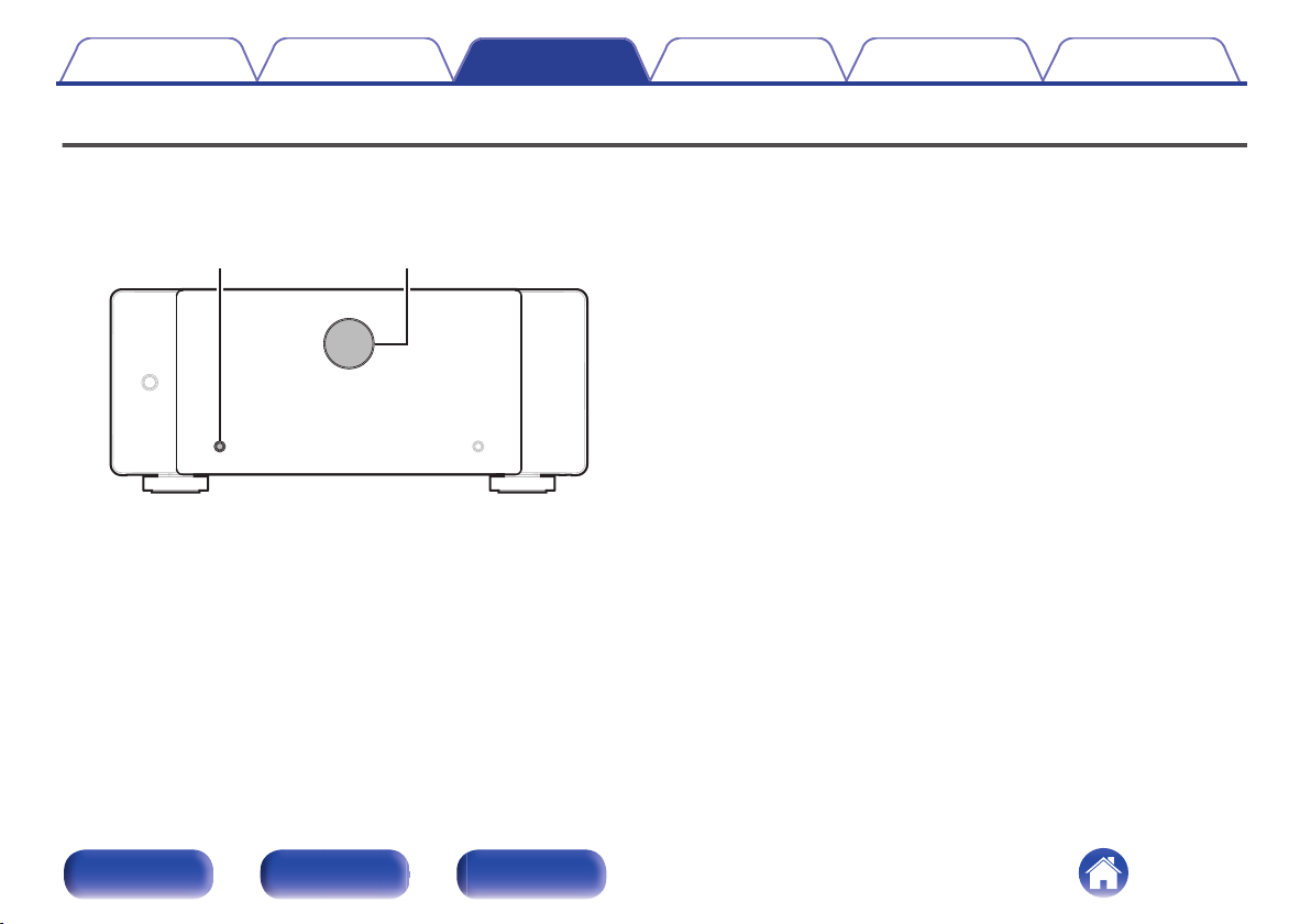
METER ON/OFF Level meter
Contents Connections Playback Tips Appendix Specifications
Turning the level meter display on or off
When the power of this unit is on, the backlight is lit and the level is displayed according to the channel 1 signal input. The meter display can be turned off
when you need darkness, such as when sleeping.
The factory setting is “On”.
Press METER ON/OFF.
1
This button toggles the level meter display on and off.
Front panel Rear panel Index
29
Page 30
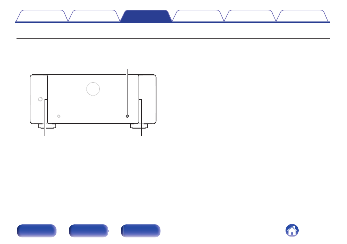
DIMMER
Illumination Illumination
Contents Connections Playback Tips Appendix Specifications
Changing the brightness of the illumination
The brightness of the illumination can be adjusted between four levels. Setting the illumination to off reduces noise that could affect playback, achieving
high audio quality.
The factory setting is the brightest illumination level.
Press DIMMER.
1
This button toggles through the illumination brightness levels.
0
Front panel Rear panel Index
30
Page 31
Contents Connections Playback Tips Appendix Specifications
Troubleshooting
If a problem should arise, first check the following:
1. Are the connections correct?
2. Is the set being operated as described in the owner’s manual?
3. Are the other devices operating properly?
If this unit does not operate properly, check the corresponding symptoms in this section.
If the symptoms do not match any of those described here, consult your dealer as it could be due to a fault in this unit. In this case, disconnect the power
immediately and contact the store where you purchased this unit.
Front panel Rear panel Index
31
Page 32
Contents
Connections Playback Tips Appendix Specifications
Power does not turn on / Power is turned off
Power does not turn on.
Check whether the power plug is correctly inserted into the power outlet. (v p. 26)
0
Power automatically turns off.
The auto standby function is set to “ON”. The unit enters standby after 15 minutes of no operation or input signal. To turn off the auto standby function,
0
set the AUTO STANDBY selector to OFF. (v p. 25)
The unit immediately turns off when the power is turned on.
The protection circuit has been activated. Unplug the unit from the power outlet, leave it for at least 1 minute and then plug it back in. (v p. 35)
0
The power turns off and the protection circuit indicator shows one long blink and four short blinks in orange.
The protection circuit has been activated due to a rise in temperature within this unit. Turn the power off, wait about an hour until this unit cools down
0
sufficiently, and then turn the power on again. (v p. 35)
Please re-install this unit in a place having good ventilation.
0
Use speakers that have the specified impedance. (v p. 12)
0
Check the speaker connections. The protection circuit may have been activated because speaker cable core wires came in contact with each other or a
0
core wire was disconnected from the connector and came in contact with the rear panel of this unit. After unplugging the power cord, take corrective
action such as firmly re-twisting the core wire or taking care of the connector, and then reconnect the wire. (v p. 12)
Turn the volume down on the amp connected to this unit, and insert the power plug again.
0
The power turns off and the protection circuit indicator shows one long blink and five short blink in orange
The protective circuit has operated. In this case, remove the power plug from the wall socket, re-examine the installation conditions of this unit, and
0
check the speaker cable connections. If the same situation occurs when the power is switched on again, contact the Marantz Service Center.
Front panel Rear panel Index
32
Page 33
Contents Connections Playback Tips Appendix Specifications
No sound comes out
No sound comes out of speakers.
Check the speaker connections and connections to the other devices. (v p. 16)
0
Alter the input selector to match the input connector (BALANCED or UNBALANCED) of the connected device. (v p. 16)
0
Insert connection cables all the way in.
0
Check that input connectors and output connectors are not reversely connected.
0
Check cables for damage.
0
0
Check that speaker cables are properly connected. Check that cable core wires come in contact with the metal part on speaker terminals. (v p. 12)
Securely tighten the speaker terminals. Check speaker terminals for looseness. (v p. 12)
0
Front panel Rear panel Index
33
Page 34
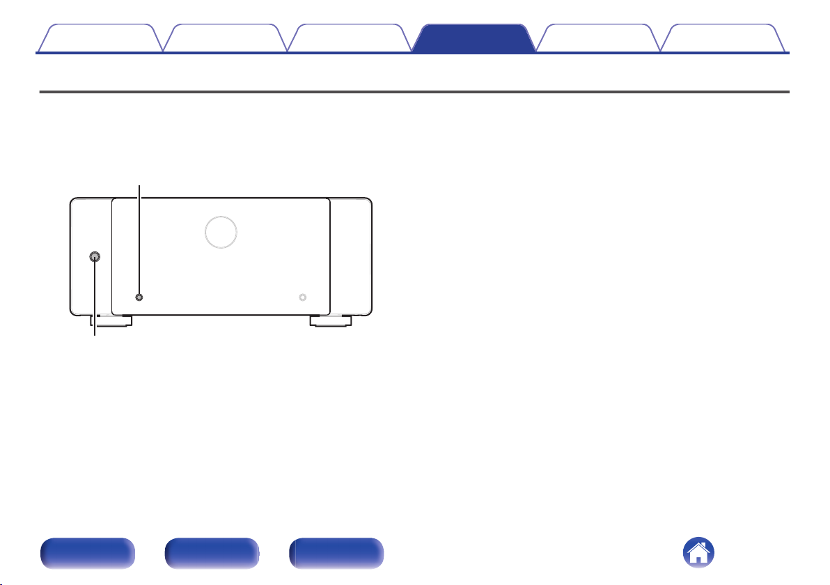
METER ON/OFF
X
Contents Connections Playback Tips Appendix Specifications
Resetting to the default values
If the unit cannot be operated, restarting the unit may improve the problem. We recommend restarting the unit before returning the settings to the default
settings.
If the operations are not improved by restarting the unit, follow the steps below.
Various settings are reset to the factory default values. Make settings again.
Turn off the power using X.
1
Press X while pressing and holding METER ON/OFF.
2
The Illumination and LEDs continue to blink while the button is being
held down.
Front panel Rear panel Index
34
Page 35
Contents Connections Playback Tips Appendix Specifications
Explanation of terms
Speaker impedance
This is certain-rated resistance of the speaker set to an alternating current
and expressed in ohms.
The smaller the impedance, the greater the output.
However, load on the amplifier is increased. Use speakers whose
impedance is supported by this unit.
Protection circuit
This is a function to prevent damage to devices within the power supply
when an abnormality such as an overload, excess voltage occurs or over
temperature for any reason.
Front panel Rear panel Index
35
Page 36
Contents
Specifications
Connections Playback Tips Appendix Specifications
Rated output: Normal, BI-AMP
Output connectors: 4 – 16 Ω/ohms (Normal, BI-AMP)
Frequency response (1 W, 8 Ω): 5 Hz – 70 kHz ±3 dB
Input sensitivity/impedance: 1.4 V / 47 kΩ/kohms (UNBALANCED)
Signal-to-noise ratio (IHF-A): 110 dB
Voltage amplification level: 29 dB
Operating temperature: 5 °C - 35 °C
Power supply: AC 230 V, 50/60 Hz
Power consumption: 400 W
Power consumption in standby mode: 0.2 W
For purposes of improvement, specifications and design are subject to change without notice.
200 W x 2 (8 Ω/ohms load, 1kHz, T.H.D. 0.05 %)
400 W x 2 (4 Ω/ohms load, 1kHz, T.H.D. 0.7 %)
BTL
400 W x 2 (8 Ω/ohms load, 1kHz, T.H.D. 0.05 %)
8 – 16 Ω/ohms (BTL)
2.8 V / 100 kΩ/kohms (BALANCED)
Front panel Rear panel Index
36
Page 37
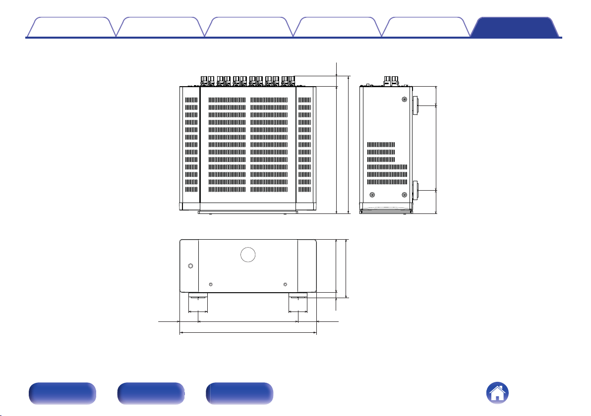
32
410
442
75 62273
172
189
17
60
60
322
442
6060
Contents Connections Playback Tips Appendix Specifications
Dimensions (Unit : mm)
o
Weight: 18.0 kg
o
Front panel Rear panel Index
37
Page 38
Contents Connections Playback Tips Appendix Specifications
Index
v Numerics
15.2-channel .................................................. 15
17.4-channel .................................................. 15
7.1-channel .................................................... 15
v A
AMP CONTROL ............................................. 20
Auto Standby ................................................. 25
v B
Bi-amp ............................................................ 18
BTL ................................................................ 19
v F
Front panel ....................................................... 6
v I
Illumination ..................................................... 30
v L
Level meter .................................................... 29
v R
Rear panel ........................................................ 8
v T
Troubleshooting ............................................. 31
v Z
ZONE2/ZONE3 .............................................. 15
v P
Protection circuit ............................................ 35
Front panel Rear panel Index
38
Page 39

© 2025 Masimo. All Rights Reserved.
3520 11011 00AS
39
 Loading...