


2500
TOROIDAL TRANSFORMER
For MARANTZ models 2500/2600
Eng. Antonio Pelli Neto
Marantz 2600 and Sansui G9000 (from my collection)
Service manuals for Marantz receivers are famous for their lack of information, or providing information that is
incorrect and/or incomplete. In the specific case of Marantz models 2500 and 2600, the manuals additionally
contain misleading information about the capacity and positioning of some electrolytic capacitors, and they do not
contain important data on voltage and current for the toroidal transformers accompanying the products. These
transformers were also famous for burning out, which presented problems in the construction of new units.
The purpose of this text is to allow electronic technicians, or even Marantz 2500/2600 owners with dead toroidal
transformers, to recover your receivers. Although my training is in Civil and Mechanical engineering, my hobby is
recovery and restoration of electronic equipment, especially equipment considered "vintage". I do not work as an
electronic technician, nor do I provide maintenance services for electronic equipment. This, as I’ve said, is just a
hobby, although I've been involved in it for over 40 years. So, I take no responsibility for the information provided
here, however I have successfully utilized it in the recovery of my own devices.
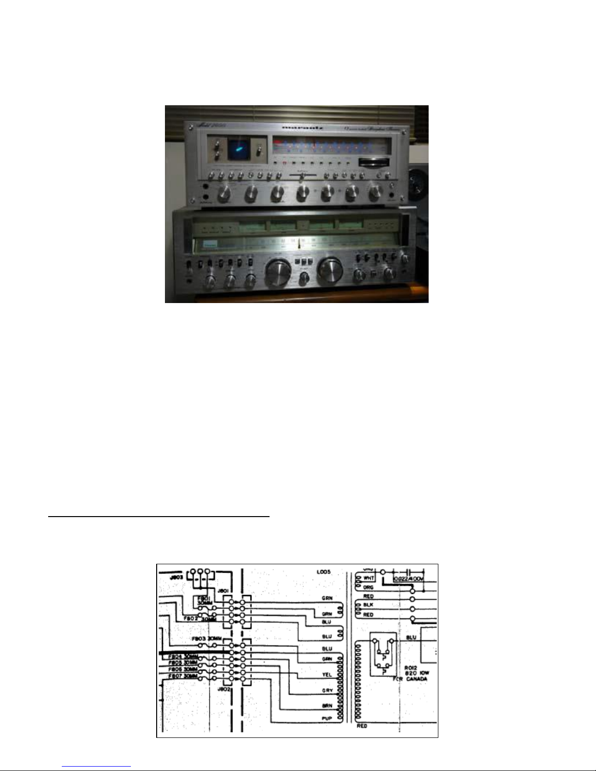
A POSSIBLE ERROR DETECTED IN SERVICE MANUAL
The Marantz 2500 and 2600 service manuals display the following diagram for connecting the toroidal
transformer:
Green
Green
Blue
Blue
Blue
Green
Yellow
Gray
Brown
Purple
Colors in the sequence
In the above schematic, the toroidal transformer has two secondaries for supplying the power amplifiers (one for
each channel) and three additional windings to supply the other components, which are connected to the P800
board. Below is a photo of this board:
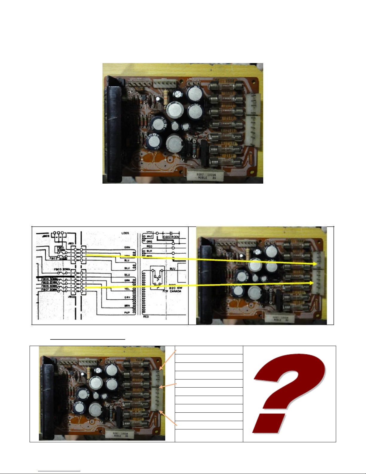
Note that this board has its original capacitors, as they hadn't yet been replaced at the time of the photo. In the
circuit shown in the Service Manual, the transformer is connected to the board using the two connectors below:
If the schematic was correct, then the connections would have the color sequence indicated below:
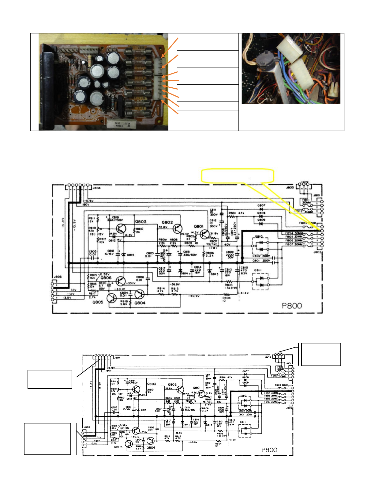
However, I have two machines, a 2600 and a 2500 - both came with the following color sequence installed:
Blue
A quick search on the Internet
shows the colors in this same
sequence.
Blue
Green
Green
Purple
Yellow
Brown
Blue
Gray
Green
Yellow (C.T.)
Dial lamp
panel
Tuner,
preamp &
phono
Oscilloscope
Considering the colors on the connectors and the power circuit of the P800 board, it is easy to see that the yellow
wire is connected to "Ground" (earth) and therefore will now be considered the CT (Center Tap) of this side:
The P800 board provides DC (direct current) and AC (alternating current) for all components of the receiver,
except for the power amplifier, which has its own side for each channel (L and R). The circuits are shown below:

Blue
8V
Blue
Green
6.3V
Green
Purple
430V
Yellow
C.T.
Brown
160V
Blue
160V
Gray
30V
Green
30V
6.3V A.C. for the C.R.T.
filament, plus 576V D.C.
In this circuit (P800), there is no indication of full voltage. The J804 connector provides DC and AC currents to the
oscilloscope, as shown below:
In the above schematic, the conclusion is that the J801 connector provides 7V AC for filaments (in green) and 8V
AC (blue), for the panel lights.
The J802 connector must therefore provide AC voltages to be rectified and generate 576V in DC, as well as 180V
and 41.4V DC supplies. Therefore, the pinout is as follows (all voltages in AC):
The 180V circuit is used to adjust the focus of the oscilloscope, ranging from 50V to 250V. This circuit is derived
from the Marantz 4400.
The current of each circuit is indicated on the board. Thus, the analysis is complete this side of the toroidal
transformer. For the amplifier, the currents and the voltages are listed on the next page:
 Loading...