

Page 1
S Model
Manitowoc
Ice Machines
Technician’s
Handbook
This manual is updated as new information and models
are released. Visit our website for the latest manual.
America’s #1 Selling Ice Machine
Part Number 80-1479-3 7/10
www.manitowocice.com
Page 2

Page 3
Safety Notices
!
Warning
!
Caution
Important
As you work on Manitowoc equipment, be sure to pay
close attention to the safety notices in this handbook.
Disregarding the notices may lead to serious injury
and/or damage to the equipment.
Throughout this handbook, you will see the following
types of safety notices:
Text in a Warning b ox alerts yo u to a p otential
personal injury si tuation. Be su re to read the
Warning st atement before proceeding, and work
carefully.
Text in a Caution bo x alerts you to a si tuation in
which you could damage the equipment. Be sure
to read the Caution statement before proceeding,
and work carefully.
Procedural Notices
As you work on Manitowoc equipment, be sure to read
the procedural notices in this handbook. These notices
supply helpful information which may assist you as
you work.
Throughout this handbook, you will see the following
types of procedural notices:
Text in an Impo rtant b ox provid es you wi th
information t hat ma y h elp yo u perform a
procedure more ef ficiently. Di sregarding thi s
information will not cause damage or injury, but it
may slow you down as you work.
Page 4
NOTE: Text set off as a Note provides you with simple,
!
Caution
Important
! Warning
We reserve the right to make product
improvements at any time. Specifications and
design are subject to change without notice.
but useful, extra information about the procedure you
are performing.
Read These Before Proceeding:
Proper i nstallation, ca re and ma intenance are
essential for maximum performance and troublefree op eration of you r Manitowo c eq uipment. If
you en counter prob lems not covered by this
handbook, do no t procee d, contact Ma nitowoc
Foodservice. We wi ll b e happy to p rovide
assistance.
Routine ad justments and main tenance
procedures outlin ed in thi s handbook are not
covered by the warranty.
PERSONAL INJURY POTENTIAL
Do n ot ope rate eq uipment that has b een
misused, ab used, ne glected, d amaged, o r
altered/modified from that of origi nal
manufactured specifications.
Page 5

Table of Contents
General Information
Model Numbers . . . . . . . . . . . . . . . . . . . . . 9
How to Read a Model Number . . . . . . 10
Ice Cube Sizes . . . . . . . . . . . . . . . . . . . . . 10
Model/Serial Number Location . . . . . . . . 11
Energy Efficient Ice Machine
Serial Breaks . . . . . . . . . . . . . . . . . . . . . . . 12
Ice Machine Warranty Information . . . . . 13
Owner Warranty Registration Card . . . 13
Commercial Warranty Coverage . . . . . 14
Residential Ice Machine Warranty . . . . 16
Installation
Location of Ice Machine . . . . . . . . . . . . . . 21
Ice Machine Clearance Requirements . . 22
Ice Machine Heat of Rejection . . . . . . . . . 23
Remote Condenser Line Set Installation
. . . . . . . . . . . . . . . . . . . . . . . . . . . . . . .24
Calculating Remote Condenser
Installation Distances . . . . . . . . . . . . . 25
Lengthening or Reducing Line Sets . . 27
Connecting A Line Set . . . . . . . . . . . . 28
Component Identification
S Model Single Evaporator Models . . . . . 29
S Model Quad Evaporator Models . . . . . 30
Maintenance
General . . . . . . . . . . . . . . . . . . . . . . . . . . . 31
Cleaning / Sanitizing Procedure . . . . . . . 32
Cleaning Procedure . . . . . . . . . . . . . . 32
Parts Removal for Cleaning/Sanitizing 34
Procedure to Clean Heavily Scaled
Ice Machines . . . . . . . . . . . . . . . . . . . . . . .40
General . . . . . . . . . . . . . . . . . . . . . . . . 40
Cleaning Procedure . . . . . . . . . . . . . . 40
Parts Removal for Cleaning/Sanitizing 43
Part Number 80-1479-3 7/10 5
Page 6

Removal from Service/Winterization . . . 57
Self-Contained Air-Cooled Ice Machines 57
Water-Cooled Ice Machines . . . . . . . . 58
Remote Ice Machines . . . . . . . . . . . . . 58
Sequence of Operation
Self Contained Air or Water Cooled . . . . 59
Single & Quad Evaporator Models . . . 59
Safety Timers . . . . . . . . . . . . . . . . . . . . . . 64
Safety Limits . . . . . . . . . . . . . . . . . . . . . . 65
Remotes . . . . . . . . . . . . . . . . . . . . . . . 72
Troubleshooting
Safety Limits . . . . . . . . . . . . . . . . . . . . . . 81
Quad Evaporator Machines Only . . . . 82
Analyzing Why a Safety Limit Stopped the
Ice Machine . . . . . . . . . . . . . . . . . . . . 84
Safety Limit #1 . . . . . . . . . . . . . . . . . . 85
Safety Limit #2 . . . . . . . . . . . . . . . . . . 86
Safety Limit #3 . . . . . . . . . . . . . . . . . . 87
Control Board Testing . . . . . . . . . . . . . . . 88
Control Board Test Cycle . . . . . . . . . . 88
Troubleshooting By Symptom . . . . . . . . 89
Symptom #1 Ice Machine will not run . 90
Compressor Electrical Diagnostics . . . 92
Symptom #2 Low Productionand/or Long
Freeze Cycle . . . . . . . . . . . . . . . . . . . . 94
Symptom #2 - Freeze Cycle Refrigeration
System Operational Analysis Tables . 96
Freeze Cycle Refrigeration System Opera-
tional Analysis Table Procedures . . . . 105
Harvest Problems . . . . . . . . . . . . . . . . . . 126
Symptom #3 Ice Will Not Harvest, Cubes
Are Not Melted . . . . . . . . . . . . . . . . . . 127
Symptom #3 - Traditional Remotes Only
. . . . . . . . . . . . . . . . . . . . . . . . . . . . . . 129
Symptom #4 Will Not Harvest, Cubes Are
Melted . . . . . . . . . . . . . . . . . . . . . . . . . 131
6 Part Number 80-1479-3 7/10
Page 7

Component Check Procedures
Electrical Components . . . . . . . . . . . . . . . 135
Main Fuse . . . . . . . . . . . . . . . . . . . . . . 135
ICE/OFF/CLEAN Toggle Switch . . . . . 136
Bin Switch . . . . . . . . . . . . . . . . . . . . . . 137
Cleaning the Ice Thickness or Water Level
Probe . . . . . . . . . . . . . . . . . . . . . . . . . . 140
Water Level Control Circuitry . . . . . . . 141
Ice Thickness Probe (Harvest Initiation)
. . . . . . . . . . . . . . . . . . . . . . . . . . . . . . .146
Harvest Assist Air Pump . . . . . . . . . . .151
Compressor Electrical Diagnostics . . . . 152
Diagnosing Start Components . . . . . . 154
Refrigeration Components . . . . . . . . . . . 158
High Pressure Cutout (HPCO) Control 158
Fan Cycle Control . . . . . . . . . . . . . . . . 159
Water Regulating Valve . . . . . . . . . . . 160
Harvest Pressure Regulating (HPR) System
Remotes Only . . . . . . . . . . . . . . . . . . . 161
Head Pressure Control Valve . . . . . . . 164
Low Pressure Cutout (LPCO) Control . 167
Harvest Pressure Solenoid Valve . . . . 168
Refrigerant Recovery/Evacuation . . . . . . 169
Normal Self-Contained Model Procedures
. . . . . . . . . . . . . . . . . . . . . . . . . . . . . . .169
Normal Remote Model Procedures . . . 173
System Contamination Clean-Up . . . . . . 178
Determining Severity Of Contamination 178
Cleanup Procedure . . . . . . . . . . . . . . . 180
Replacing Pressure Controls Without Re-
moving Refrigerant Charge . . . . . . . . . 183
Specifications
Main Fuse . . . . . . . . . . . . . . . . . . . . . . 185
Fan Cycle Control . . . . . . . . . . . . . . . . 185
High Pressure Cutout (HPCO) Control 185
Filter-Driers . . . . . . . . . . . . . . . . . . . . . 186
Total System Refrigerant Charge . . . . 187
Part Number 80-1479-3 7/10 7
Page 8

Charts
Cycle Times/24-Hour Ice Production/
Refrigerant Pressure Charts . . . . . . . . . . 191
S300 Series . . . . . . . . . . . . . . . . . . . . 192
S320 Series . . . . . . . . . . . . . . . . . . . . 196
S420 Series . . . . . . . . . . . . . . . . . . . . 198
S450 Series . . . . . . . . . . . . . . . . . . . . 202
S500 Series . . . . . . . . . . . . . . . . . . . . 206
S600 Series . . . . . . . . . . . . . . . . . . . . 215
S850 Series . . . . . . . . . . . . . . . . . . . . 218
S1000 Series . . . . . . . . . . . . . . . . . . . 227
S1200 Series . . . . . . . . . . . . . . . . . . . 236
S1400 Series . . . . . . . . . . . . . . . . . . . 242
S1600 Series . . . . . . . . . . . . . . . . . . . 253
S1800 Series . . . . . . . . . . . . . . . . . . . 256
S3300 Series . . . . . . . . . . . . . . . . . . . 265
Diagrams
Wiring Diagrams . . . . . . . . . . . . . . . . . . . 267
Wiring Diagram Legend . . . . . . . . . . . 267
Wiring Diagrams Before Energy Efficient &
EnergyStar Machines . . . . . . . . . . . . . 268
Wiring Diagrams for Energy Efficient & En-
ergyStar Machines . . . . . . . . . . . . . . . 279
Electronic Control Board . . . . . . . . . . . . 290
Single and Twin Evaporator . . . . . . . . 290
Single and Twin Evaporator With Test But-
ton . . . . . . . . . . . . . . . . . . . . . . . . . . . 291
Quad Evaporator Ice Machines . . . . . 292
Refrigeration Tubing Schematics . . . . . 293
Self-Contained Air- or
Water -Cooled Models . . . . . . . . . . . . 293
Remote Models . . . . . . . . . . . . . . . . . 295
8 Part Number 80-1479-3 7/10
Page 9

General Information
Model Numbers
This manual covers the following models:
Self-Contained
Air-Cooled
SD0302A
SY0304A
SD0322A
SY0324A
SR0420A
SD0422A
SY0424A
SD0452A
SY0454A
SR0500A
SD0502A
SY0504A
SD0602A
SY0604A
SR0850A
SD0852A
SY0854A
SR1000A
SD1002A
SY1004A
SD1202A
SY1204A
SD1402A
SY1404A
SR1600A
SD1602A
SY1604A
SR1800A
SD1802A
SY1804A
---
---
---
---
NOTE: Model numbers ending in 3 indicate a 3
phase unit. Example: SY1004A3.
Self-Contained
Water-Cooled
SD0303W
SY0305W
SD0323W
SY0325W
SR0421W
SD0423W
SY0425W
SD0453W
SY0455W
SR0501W
SD0503W
SY0505W
SD0603W
SY0605W
SR0851W
SD0853W
SY0855W
SR1001W
SD1003W
SY1005W
SD1203W
SY1205W
SD1403W
SY1405W
SR1601W
SD1603W
SY1605W
SR1801W
SD1803W
SY1805W
SD3303W
SD3303WHP
SY3305W
SY3305WHP
Remote
---
---
---
---
---
---
---
---
SD0592N
SY0594N
SD0692N
SY0694N
SR0890N
SD0892N
SY0894N
SR1090N
SD1092N
SY1094N
---
---
SD1492N
SY1494N
SR1690N
SD1692N
SY1694N
SR1890N
SD1892N
SY1894N
---
---
---
---
Part Number 80-1479-3 7/10 9
Page 10
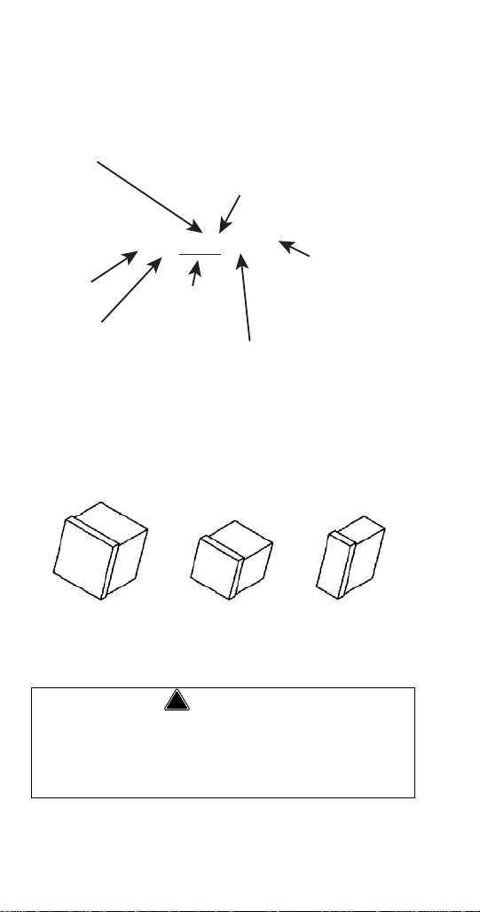
HOW TO READ A MODEL NUMBER
! Warning
S Y 1094 N SI
ICE MACHINE
MODEL
ICE CUBE SIZE
R REGULAR
D DICE
Y HALF DICE
# CUBE SIZE
0 REGULAR
1 REGULAR
2 DICE
3 DICE
4 HALF-DICE
5 HALF-DICE
CONDENSER TYPE
AIR-COOLED
WATER-COOLED
AIR-COOLED
WATER-COOLED
AIR-COOLED
WATER-COOLED
A SELF-CONTAINED AIR-COOLED
W SELF-CONTAINED WATER-COOLED
N REMOTE AIR-COOLED
9 REMOTE
AIR-COOLED
CONDENSER TYPE
ICE MACHINE
SERIES
ADDITIONAL SPECS
3 PHASE
M MARINE UNIT
HP HIGH PRESSURE
WATER VALVE
SI AUCS-SI INCLUDED
Ice Cube Sizes
Regular
1-1/8" x 1-1/8" x 7/8"
2.86 x 2.86 x 2.22 cm
2.22 x 2.22 x2.22 cm
Dice
7/8" x 7/8" x 7/8"
Half Dice
3/8" x 1-1/8" x 7/8"
0.95 x 2.86 x 2.22 cm
Personal Injury Potential
Do not operate equipment that has been misused,
abused, neglected, damaged, or altered/modified
from that of original manufactured specifications.
10 Part Number 80-1479-3 7/10
Page 11

! Warning
All Man itowoc ice ma chines re quire th e ice
storage system (bin, dispenser, etc.) to
incorporate an ice deflector.
48” w ide S Model ice mach ines re quire add ing
Manitowoc Ice Deflector Kit K00 349 w hen
installing wi th non-Manitowoc ice sto rage
systems.
30” w ide S Model ice mach ines re quire add ing
Manitowoc Ice Deflector Kit K00 347 w hen
installing wi th non-Manitowoc ice sto rage
systems.
Prior to using a non -Manitowoc ice sto rage
system with other Manitowoc ice machin es,
contact th e manufacturer to assu re th eir ice
deflector is comp atible wi th Mani towoc ice
machines.
Model/Serial Number Location
These numbers are required when requesting
information from your local Manitowoc Distributor,
service representative, or Manitowoc Ice, Inc. The
model and serial number are listed on the OWNER
WARRANTY REGISTRATION CARD. They are also
listed on the MODEL/SERIAL NUMBER DECAL
affixed to the ice machine.
Part Number 80-1479-3 7/10 11
Page 12
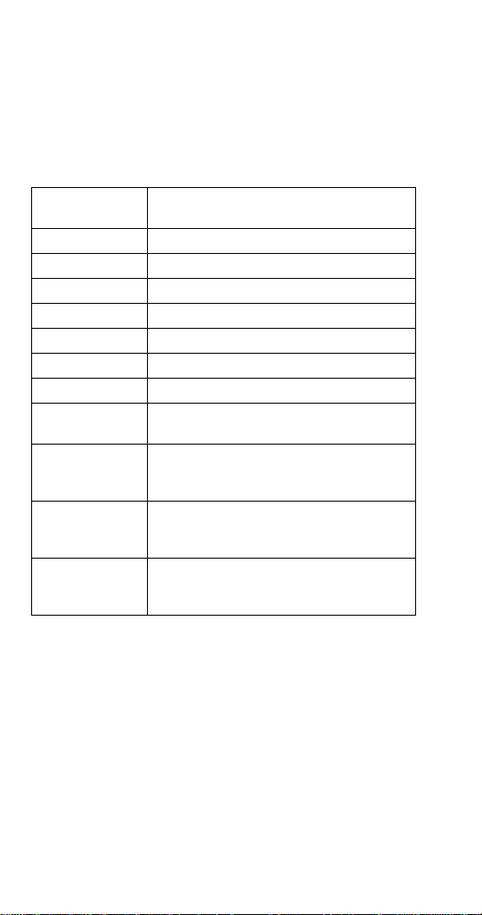
Energy Efficient Ice Machine Serial Breaks
Some specifications have changed with our release of
more Energy Efficient machines. The following
machines have a serial break to indicate when they
became more Energy Efficient.
Series Ice
Machine
S300 110704351
S420 110667970
S450 110670157
S500 110684316
S850 110683282
S1000 110697023
S1200 110707329
S1400W
S1400W
S1400A
S1400W
S1400N
S1800A
S1800W
S1800N
Serial Break/Manufacture Date for
Energy Efficient Machines
Manufacture Date After 0711
(November 2007)
Manufacture Date Between
0711 & 0905
(November 2007 & May 2009)
Manufacture Date After 0905
(May 2009)
Manufacture Date After 0910
(October 2009)
12 Part Number 80-1479-3 7/10
Page 13

Ice Machine Warranty Information
Important
OWNER WARRANTY REGISTRATION CARD
Warranty coverage begins the day the ice machine is
installed.
Complete and mail the OW NER WARRANTY
REGISTRATION C ARD as soon as p ossible to
validate the installation date.
If the OWNER WARRANTY REGISTRATION CARD is
not returned, Manitowoc will use the date of sale to the
Manitowoc Distributor as the first day of warranty
coverage for your new ice machine.
Part Number 80-1479-3 7/10 13
Page 14

COMMERCIAL WARRANTY COVERAGE
Manitowoc Ice, (hereinafter referred to as the
"COMPANY") warrants for a period of thirty-six months
from the installation date (except as limited below) that
new ice machines manufactured by the COMPANY
shall be free of defects in material or workmanship
under normal and proper use and maintenance as
specified by the COMPANY and upon proper
installation and start-up in accordance with the
instruction manual supplied with the ice machine.
The COMPANY'S warranty hereunder with respect to
the compressor shall apply for an additional twentyfour months, excluding all labor charges, and with
respect to the evaporator for an additional twenty-four
months, including labor charges.
The obligation of the COMPANY under this warranty is
limited to the repair or replacement of parts,
components, or assemblies that in the opinion of the
COMPANY are defective. This warranty is further
limited to the cost of parts, components or assemblies
and standard straight time labor charges at the
servicing location. Time and hourly rate schedules, as
published from time to time by the COMPANY, apply to
all service procedures.
Additional expenses including without limitation, travel
time, overtime premium, material cost, accessing or
removal of the ice machine, or shipping are the
responsibility of the owner, along with all maintenance,
adjustments, cleaning, and ice purchases.
Labor covered under this warranty must be performed
by a COMPANY Contracted Service Representative or
a refrigeration service agency as qualified and
authorized by the COMPANY'S local Distributor.
The COMPANY'S liability under this warranty shall in
no event be greater than the actual purchase price
paid by customer for the ice machine.
14 Part Number 80-1479-3 7/10
Page 15

The foregoing warranty shall not apply to (1) any part
or assembly that has been altered, modified, or
changed; (2) any part or assembly that has been
subjected to misuse, abuse, neglect, or accidents; (3)
any ice machine that has been installed and/or
maintained inconsistent with the technical instructions
provided by the COMPANY; or (4) any ice machine
initially installed more than five years from the serial
number production date. This warranty shall not apply
if the Ice Machine's refrigeration system is modified
with a condenser, heat reclaim device, or parts and
assemblies other than those manufactured by the
COMPANY, unless the COMPANY approves these
modifications for specific locations in writing.
THIS WARRANTY IS IN LIEU OF ALL OTHER
WARRANTIES OR GUARANTEES OF ANY
KIND, EXPRESSED OR IMPLIED, INCLUDING ANY
IMPLIED WARRANTY OF MERCHANTABILITY
OR FITNESS FOR A PARTICULAR PURPOSE.
In no event shall the COMPANY be liable for any
special, indirect, incidental or consequential damages.
Upon the expiration of the warranty period, the
COMPANY'S liability under this warranty shall
terminate. The foregoing warranty shall constitute the
sole liability of the COMPANY and the exclusive
remedy of the customer or user.
To secure prompt and continuing warranty service, the
warranty registration card must be completed and sent
to the COMPANY within five (5) days from the
installation date.
To obtain warranty service or information regarding
your Product, please contact us at:
MANITOWOC ICE
2110 So. 26th St. P.O. Box 1720,
Manitowoc, WI 54221-1720
Telephone: 920-682-0161 Fax: 920-683-7585
www.manitowocice.com
Part Number 80-1479-3 7/10 15
Page 16

RESIDENTIAL ICE MACHINE LIMITED WARRANTY
WHAT DOES THIS LIMITED WARRANTY COVER?
Subject to the exclusions and limitations below,
Manitowoc Ice, Inc. (“Manitowoc”) warrants to the
original consumer that any new ice machine
manufactured by Manitowoc (the “Product”) shall be
free of defects in material or workmanship for the
warranty period outlined below under normal use and
maintenance, and upon proper installation and startup in accordance with the instruction manual supplied
with the Product.
HOW LONG DOES THIS LIMITED WARRANTY
LAST?
Product Covered Warranty Period
Ice Machine
Twelve months from the
sale date
WHO IS COVERED BY THIS LIMITED WARRANTY?
This limited warranty only applies to the original
consumer of the Product and is not transferable.
16 Part Number 80-1479-3 7/10
Page 17

WHAT ARE MANITOWOC ICE’S OBLIGATIONS
UNDER THIS LIMITED WARRANTY?
If a defect arises and Manitowoc receives a valid
warranty claim prior to the expiration of the warranty
period, Manitowoc shall, at its option: (1) repair the
Product at Manitowoc’s cost, including standard
straight time labor charges, (2) replace the Product
with one that is new or at least as functionally
equivalent as the original, or (3) refund the purchase
price for the Product. Replacement parts are
warranted for 90 days or the balance of the original
warranty period, whichever is longer. The foregoing
constitutes Manitowoc’s sole obligation and the
consumer’s exclusive remedy for any breach of this
limited warranty. Manitowoc’s liability under this limited
warranty is limited to the purchase price of Product.
Additional expenses including, without limitation,
service travel time, overtime or premium labor
charges, accessing or removing the Product, or
shipping are the responsibility of the consumer.
HOW TO OBTAIN WARRANTY SERVICE
To obtain warranty service or information regarding
your Product, please contact us at:
MANITOWOC ICE
2110 So. 26th St.
P.O. Box 1720,
Manitowoc, WI 54221-1720
Telephone: 920-682-0161 Fax: 920-683-7585
www.manitowocice.com
Part Number 80-1479-3 7/10 17
Page 18

WHAT IS NOT COVERED?
This limited warranty does not cover, and you are
solely responsible for the costs of: (1) periodic or
routine maintenance, (2) repair or replacement of the
Product or parts due to normal wear and tear, (3)
defects or damage to the Product or parts resulting
from misuse, abuse, neglect, or accidents, (4) defects
or damage to the Product or parts resulting from
improper or unauthorized alterations, modifications, or
changes; and (5) defects or damage to any Product
that has not been installed and/or maintained in
accordance with the instruction manual or technical
instructions provided by Manitowoc. To the extent that
warranty exclusions are not permitted under some
state laws, these exclusions may not apply to you.
E
XCEPT AS STATED IN THE FOLLOWING SENTENCE, THIS
IMITED WARRANTY IS THE SOLE AND EXCLUSIVE
L
W
ARRANTY OF MANITOWOC WITH REGARD TO THE
P
RODUCT. ALL IMPLIED WARRANTIES ARE STRICTLY
IMITED TO THE DURATION OF THE LIMITED WARRANTY
L
A
PPLICABLE TO THE PRODUCTS AS STATED ABOVE,
I
NCLUDING BUT NOT LIMITED TO, ANY WARRANTY OF
ERCHANTABILITY OR OF FITNESS FOR A PARTICULAR
M
P
URPOSE.
Some states do not allow limitations on how long an
implied warranty lasts, so the above limitation may not
apply to you.
18 Part Number 80-1479-3 7/10
Page 19

IN NO EVENT SHALL MANITOWOC OR ANY OF ITS
A
FFILIATES BE LIABLE TO THE CONSUMER OR ANY
THER PERSON FOR ANY INCIDENTAL, CONSEQUENTIAL
O
O
R SPECIAL DAMAGES OF ANY KIND (INCLUDING,
W
ITHOUT LIMITATION, LOSS OF PROFITS, REVENUE OR
USINESS) ARISING FROM OR IN ANY MANNER
B
C
ONNECTED WITH THE PRODUCT, ANY BREACH OF THIS
L
IMITED WARRANTY, OR ANY OTHER CAUSE
HATSOEVER, WHETHER BASED ON CONTRACT, TORT
W
O
R ANY OTHER THEORY OF LIABILITY.
Some states do not allow the exclusion or limitation of
incidental or consequential damages, so the above
limitation or exclusion may not apply to you.
HOW STATE LAW APPLIES
This limited warranty gives you specific legal rights,
and you may also have rights that vary from state to
state or from one jurisdiction to another.
REGISTRATION CARD
To secure prompt and continuing warranty service, this
warranty registration card must be completed and sent
to Manitowoc within thirty (30) days from the sale date.
Complete the registration card and send it to
Manitowoc.
Part Number 80-1479-3 7/10 19
Page 20

20 Part Number 80-1479-3 7/10
This Page Intentionally Left Blan k
Page 21

Installation
!
Warning
PERSONAL INJURY POTENTIAL
Remove a ll i ce machi ne p anels before lifting a nd
installing.
Location of Ice Machine
The location selected for the ice machine head section
must meet the following criteria. If any of these criteria
are not met, select another location.
• The location must be free of airborne and other
contaminants.
• Self contained air and water cooled - The air
temperature must be at least 35°F (1.6°C), but
must not exceed 110°F (43.4°C).
• Remote air cooled - The air temperature must be
at least -20°F (-29°C), but must not exceed 120°F
(49°C)
• Ice Making Water Inlet - Water Pressure must be
at least 20 psi (1.38 bar), but must not exceed 80
psi (5.52 bar).
• Condenser Water Inlet - Water Pressure must be
at least 20 psi (1.38 bar), but must not exceed
150 psi (10.34 bar). S3300W-HP units allow water
pressure up to 350 psig (24.13 bar)
• The location must not be near heat-generating
equipment or in direct sunlight and protected from
weather.
• The location must not obstruct air flow through or
around the ice machine. Refer to chart below for
clearance requirements.
• The ice machine must be protected if it will be
subjected to temperatures below 32°F (0°C).
Failure caused by exposure to freezing
temperatures is not covered by the warranty. See
“Removal from Service/Winterization”
.
Part Number 80-1479-3 7/10 21
Page 22
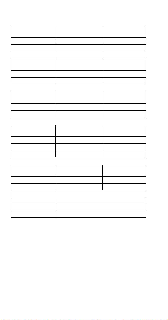
Ice Machine Clearance Requirements
S300
Top/Sides 16" (40.6 cm) 8" (20.3 cm)
Back 5" (12.7 cm) 5" (12.7 cm)
Self-Contained
Air-Cooled
Self-Contained
Water-Cooled
S320/S450/S500/
S600/S850/S1000
Top/Sides 8" (20.3 cm) 8" (20.3 cm)
Back 5" (12.7 cm) 5" (12.7 cm)
S420
Top/Sides 12" (30.5 cm) 8" (20.3 cm)
Back 5" (12.7 cm) 5" (12.7 cm)
S1200
To p 8" (20.3 cm) 8" (20.3 cm)
Sides 12" (30.5 cm) 8" (20.3 cm)
Back 5" (12.7 cm) 5" (12.7 cm)
S1400/S1600/
S1800
Top/Sides 24" (61.0 cm) 8" (20.3 cm)
Back 12" (30.5 cm) 5" (12.7 cm)
**
S3300
Top/Sides 8" (20.3 cm)
Back 24" (61.0 cm)
* There is no minimum clearance required for water-cooled or
remote ice machines. This value is recommended for efficient
operation and servicing only.
** S3300 - 24” on all sides is recommended to allow access without
moving the bin/ice machine.
Self-Contained
Air-Cooled
Self-Contained
Air-Cooled
Self-Contained
Air-Cooled
Self-Contained
Air-Cooled
Water-Cooled
Water-Cooled and
Remote*
Water-Cooled and
Remote*
Water-Cooled and
Remote*
Water-Cooled
and Remote*
*
22 Part Number 80-1479-3 7/10
Page 23
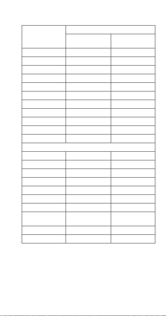
Ice Machine Heat of Rejection
Series Ice
Machine
S300 3,800 6,000
S320 3,800 6,000
S420/S450 7,000 9,600
S500 7,000 9,600
S600 9,000 13,900
S850 12,000 18,000
S1000 16,000 22,000
S1200 19,000 28,000
S1400 19,000 28,000
S1600 21,000 31,000
S1800 24,000 36,000
Energy Efficient Machines
S300 5,000 6,000
S420/S450 5,900 6,900
S500 6,100 6,900
S850 13,000 16,000
S1000 17,700 21,000
S1200 20,700 24,500
S1400W 25,000 28,000
S1400A/
S1400N
S1800 31,000 36,000
S3300 45,000 51,000
*BTU/Hour
Because the heat of rejection varies during the ice making
cycle, the figure shown is an average.
Heat of Rejection
Air
Conditioning*
23,500 27,000
Peak
Part Number 80-1479-3 7/10 23
Page 24
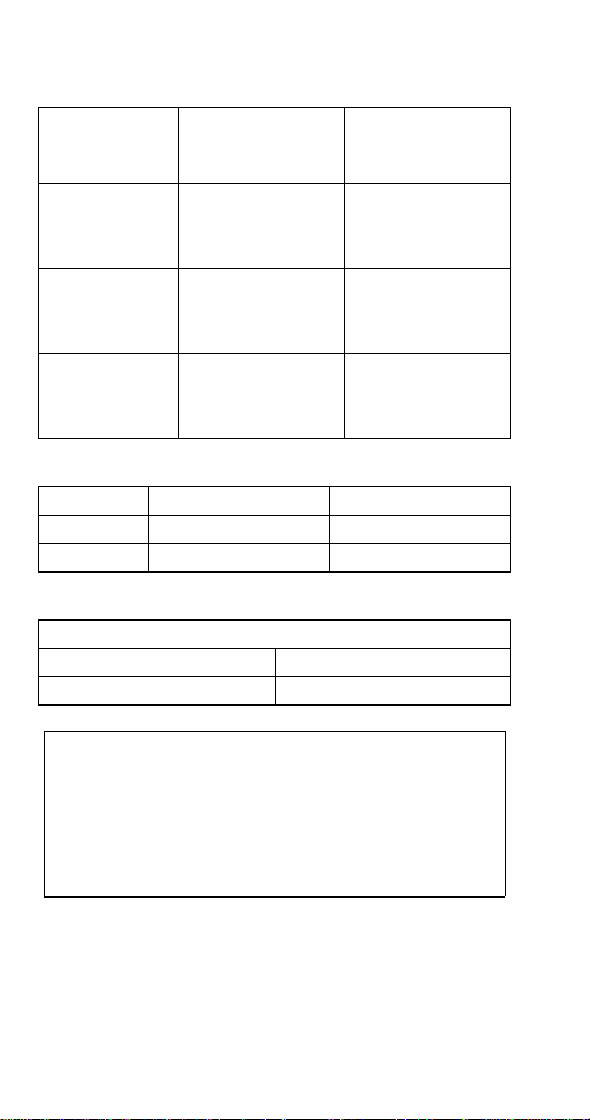
REMOTE CONDENSER LINE SET INSTALLATION
Important
Remote Single
Ice Machine
S500 JC0495
S600
S800
S1000
S1400
S1600
S1800
*Line Set Discharge Line Liquid Line
RT 1/2" (1.27 cm) 5/16" (.79 cm)
RL 1/2" (1.27 cm) 3/8" (.95 cm)
Air Temperature Around the Condenser
Minimum Maximum
-20°F (-29°C) 120°F (49°C)
Circuit
Condenser
JC0895
JC1395
Line Set*
RT-20-R404A
RT-35-R404A
RT-50-R404A
RT-20-R404A
RT-35-R404A
RT-50-R404A
RL-20-R404A
RL-35-R404A
RL-50-R404A
Manitowoc remote systems are only approved
and warranted as a complete new package.
Warranty on the refrigeration system will be
void if a new ice machine head section is
connected to pre-existing (used) tubing or
remote condensers or vice ve r sa .
24 Part Number 80-1479-3 7/10
Page 25
CALCULATING REMOTE CONDENSER
!
Caution
INSTALLATION DISTANCES
NOTE: Manitowoc warrants only complete new and
unused remote packages. Warranty on the
refrigeration system will be void if a new ice machine
head section is connected to existing (used) tubing or
condensers.
Line Set Length
The maximum length is 100' (30.5 m).
The ice machine compressor must have the proper oil
return. The receiver is designed to hold a charge
sufficient to operate the ice machine in ambient
temperatures between -20°F (-28.9°C) and 120°F
(49°C), with line set lengths of up to 100' (30.5 m).
Line Set Rise/Drop
The maximum rise is 35' (10.7 m).
The maximum drop is 15' (4.5 m).
If a li ne set has a rise followed by a drop, another
rise cann ot be mad e. Likew ise, if a li ne se t h as a
drop fo llowed by a rise, another drop cannot be
made.
Part Number 80-1479-3 7/10 25
Page 26

Calculated Line Set Distance
The maximum calculated distance is 150' (45.7 m).
Line set rises, drops, horizontal runs (or combinations
of these) in excess of the stated maximums will
exceed compressor start-up and design limits. This will
cause poor oil return to the compressor.
Make the following calculations to make sure the line
set layout is within specifications.
1. Insert the measured rise into the formula below.
Multiply by 1.7 to get the calculated rise.
(Example: A condenser located 10 feet above the
ice machine has a calculated rise of 17 feet.)
2. Insert the measured drop into the formula below.
Multiply by 6.6 to get the calculated drop.
(Example. A condenser located 10 feet below the
ice machine has a calculated drop of 66 feet.)
3. Insert the measured horizontal distance into the
formula below. No calculation is necessary.
4. Add together the calculated rise, calculated
drop, and horizontal distance to get the total
calculated distance. If this total exceeds 150'
(45.7 m), move the condenser to a new location
and perform the calculations again.
26 Part Number 80-1479-3 7/10
Page 27

Maximum Line Set Distance Formula
Step 1
Measured Rise ____ X 1.7 = ______Calculated Rise
(35 ft. Max)
Step 2
Measured Drop ____ X 6.6 = ______Calculated Drop
(15 ft. Max.)
Step 3
Measured Horizontal Distance = _________Horizontal
(100 ft. Max.) Distance
Step 4
Total Calculated Distance = ________Total Calculated
(150 ft. Max.) Distance
LENGTHENING OR REDUCING LINE SET LENGTHS
In most cases, by routing the line set properly,
shortening will not be necessary. When shortening or
lengthening is required, do so before connecting the
line set to the ice machine or the remote condenser.
This prevents the loss of refrigerant in the ice machine
or condenser.
The quick connect fittings on the line sets are
equipped with Schraeder valves. Use these valves to
recover any vapor charge from the line set. When
lengthening or shortening lines follow good
refrigeration practices, purge with nitrogen and
insulate all tubing. Do not change the tube sizes.
Evacuate the lines and place about 5 oz (143g) of
vapor refrigerant charge in each line.
Part Number 80-1479-3 7/10 27
Page 28

CONNECTING A LINE SET
1. Remove the dust caps from the line set,
condenser and ice machine.
2. Apply refrigeration oil to the threads on the quick
disconnect couplers before connecting them to
the condenser.
3. Carefully thread the female fitting to the
condenser or ice machine by hand.
4. Tighten the couplings with a wrench until they
bottom out.
5. Turn an additional 1/4 turn to ensure proper
brass-to-brass seating. Torque to the following
specifications:
Liquid Line Discharge Line
10-12 ft lb.
(13.5-16.2 N•m)
35-45 ft lb.
(47.5-61.0 N•m)
6. Check all fittings and valve caps for leaks.
7. Make sure Schraeder cores are seated and
Schraeder caps are on and tight.
28 Part Number 80-1479-3 7/10
Page 29
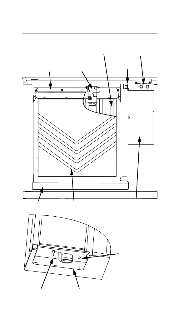
Component Identification
WATER CURTAIN
CONTROL BOX
WATER
DISTRIBUTION
TUBE
TOGGLE
SWITCH
WATER
TROUGH
REFRIGERATION
ACCESS VALVES
ICE
THICKNESS
CONTROL
EVAPORATOR
WA TER LEVEL
PROBE
WATER PUMP
WATER INLET
LOCATION, THE
WA TER INLET V ALVE
IS LOCATED IN THE
REFRIGERATION
COMPARTMENT
S Model Single Evaporator Models
Part Number 80-1479-3 7/10 29
Page 30
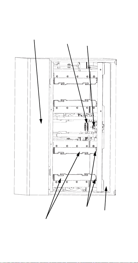
S Model Quad Evaporator Models
WATER
PUMPS
WA TER LEVEL
PROBE
EVAPORATORS
WATER
TROUGH
CONTROL
BOX
ICE DAMPERS
30 Part Number 80-1479-3 7/10
Page 31

Maintenance
General
Clean and sanitize the ice machine every six months
for efficient operation. If the ice machine requires more
frequent cleaning and sanitizing, consult a water care
professional to test the water quality and recommend
appropriate water treatment. An extremely dirty ice
machine must be taken apart for cleaning and
sanitizing.
Manitowoc Ice Machine Cleaner and Sanitizer are the
only products approved for use in Manitowoc ice
machines.
This Manitowoc Ice Machine has two separate
cleaning procedures.
Cleaning/Sanitizing Procedure
This procedure must be performed a minimum of once
every six months.
• The ice machine and bin must be disassembled
cleaned and sanitized
• All ice produced during the cleaning and sanitizing
procedures must be discarded
• Removes mineral deposits from areas or surfaces
that are in direct contact with water
Heavily Scaled Cleaning Procedure
Perform this procedure if you have some or all of these
symptoms.
• Ice machine stops on Safety Shutdown
• Your water has a high concentration of minerals
• The ice machine has not been on a regular
maintenance schedule.
Part Number 80-1479-3 7/10 31
Page 32

Cleaning / Sanitizing Procedure
!
Caution
!
Caution
!
Warning
!
Caution
Use on ly Mani towoc app roved Ice Machi ne
Cleaner and Sanitize r fo r this application
(Manitowoc Cleaner part number 94-0546-3 and
Manitowoc Sanitizer part number 94-0565-3). It is
a violation of Federal law to use these solutions in
a man ner inconsistent with the ir la beling. Re ad
and und erstand a ll l abels prin ted on bo ttles
before use.
CLEANING PROCEDURE
Do n ot mi x Clea ner a nd Sa nitizer sol utions
together. It is a viol ation of Fe deral law to use
these solutions in a manner inconsistent with their
labeling.
Wear rubbe r gloves an d safe ty go ggles (and/or
face shield) when handling ice machin e Cleaner
or Sanitizer.
Ice machine cleaner is used to remove lime scale and
mineral deposits. Ice machine sanitizer disinfects and
removes algae and slime.
Step 1 Remove front door and top cover. This will
allow easiest access for adding cleaning and
sanitizing solutions.
Step 2 Set the toggle switch to the OFF position after
ice falls from the evaporator at the end of a Harvest
cycle. Or, set the switch to the OFF position and allow
the ice to melt off the evaporator.
Never use anything to force i ce from the
evaporator. Damage may result.
32 Part Number 80-1479-3 7/10
Page 33

Step 3 Remove all ice from the bin.
!
Warning
Step 4 Place the toggle switch in the CLEAN
position. The water will flow through the water dump
valve and down the drain. Wait until the water trough
refills and water flows over the evaporator, then add
the proper amount of ice machine cleaner.
Model Amount of Cleaner
S300/S320/S420 3 ounces (90 ml)
S450/S500/S600/S850/
S1000/S1200
S1400/S1600/S1800 9 ounces (265 ml)
S3300 16 ounces (475 ml)
5 ounces (150 ml)
Step 5 Wait until the clean cycle is complete
(approximately *35 minutes). then place the toggle
switch in the OFF position and disconnect power to
the ice machine (and dispenser when used).
NOTE: *S3300 Only - 80 minutes..
Disconnect the electric power to the ice machine
at the electric service switch box.
Step 6 Remove parts for cleaning.
Please refer to the proper parts removal for your
ice machine.
Single Evaporator Ice Machines - page 34.
Quad Evaporator Ice Machines - page 35.
Part Number 80-1479-3 7/10 33
Page 34

PARTS REMOVAL FOR CLEANING/SANITIZING
A.
B.
C.
Single Evaporator Ice Machines
A. Remove the water curtain
• Gently flex the curtain in the center and remove it
from the right side.
• Slide the left pin out.
B. Remove the ice thickness probe
• Compress the hinge pin on the top of the ice
thickness probe.
• Pivot the ice thickness probe to disengage one pin
then the other. The ice thickness probe can be
cleaned at this point without complete removal. If
complete removal is desired, disconnect the ice
thickness control wiring from the control board.
C. Remove the water trough
• Depress tabs on right and left side of the water
trough.
• Allow front of water trough to drop as you pull
forward to disengage the rear pins.
NOTE: Proceed to page 37, Step 7.
34 Part Number 80-1479-3 7/10
Page 35

Quad Evaporator Ice Machines
A.Remove the water trough shield.
• Grasp the water trough shield in the center and the
left end.
• Flex the water trough shield in the center and pull
the left end forward until clear of the side wall.
Repeat for the right end.
• Pull water trough shield forward to remove.
B. Remove Splash Shields.
• Grasp the top center of splash shields.
• Lift up and then out.
C. Remove ice thickness probe.
• Compress the hinge pin on the top of the ice
thickness probe.
• Pivot the ice thickness probe to disengage one pin
then the other. The ice thickness probe can be
cleaned at this point without complete removal. If
complete removal is desired, disconnect the ice
thickness control wiring from the control board.
D. Remove the water pump assembly
• Disconnect the vinyl distribution tube from both
water pumps.
• Disconnect the water pump and water level probe
electrical connections.
• Remove two thumbscrews and lift the water pump
assembly out of the ice machine.
E. Remove the water trough.
• Depress the two tabs on the top of the water
trough.
• Turn left and right ice dampers down to clear water
trough.
• Pull forward on the water trough to remove.
NOTE: Proceed to page 37, Step 7.
Continued on next page …
Part Number 80-1479-3 7/10 35
Page 36

A
B
C
D
E
36 Part Number 80-1479-3 7/10
Page 37

Step 7 Mix a solution of cleaner and warm water.
Depending upon the amount of mineral buildup, a
larger quantity of solution may be required. Use the
ratio in the table below to mix enough solution to
thoroughly clean all parts.
Solution Type Water Mixed With
Cleaner 1 gal. (4 l)
16 oz (500 ml)
cleaner
Step 8 Use 1/2 of the cleaner/water mixture to clean
all components. The cleaner solution will foam when it
contacts lime scale and mineral deposits; once the
foaming stops use a soft-bristle nylon brush, sponge
or cloth (NOT a wire brush) to carefully clean the parts.
Soak parts for 5 minutes (15 - 20 minutes for heavily
scaled parts). Rinse all components with clean water.
Step 9 While components are soaking, use 1/2 of the
cleaner/water solution to clean all foodzone surfaces
of the ice machine and bin (or dispenser). Use a nylon
brush or cloth to thoroughly clean the following ice
machine areas:
• Side walls
• Base (area above water trough)
• Evaporator plastic parts - including top, bottom,
and sides
• Bin or dispenser
Rinse all areas thoroughly with clean water.
Continued on next page …
Step 10 Mix a solution of sanitizer and warm water.
Solution Type Water Mixed With
Sanitizer 6 gal. (23 l)
4 oz (120 ml)
sanitizer
Step 11 Use 1/2 of the sanitizer/water solution to
sanitize all removed components. Use a spray bottle
to liberally apply the solution to all surfaces of the
removed parts or soak the removed parts in the
sanitizer/water solution. Do not rinse parts after
sanitizing.
Part Number 80-1479-3 7/10 37
Page 38

Step 12 Use 1/2 of the sanitizer/water solution to
sanitize all foodzone surfaces of the ice machine and
bin (or dispenser). Use a spray bottle to liberally apply
the solution. When sanitizing, pay particular attention
to the following areas:
• Side walls
• Base (area above water trough)
• Evaporator plastic parts - including top, bottom and
sides
• Bin or dispenser
Do not rinse the sanitized areas.
Step 13 Replace all removed components.
Step 14 Wait 30 minutes.
38 Part Number 80-1479-3 7/10
Page 39

Step 15 Reapply power to the ice machine and place
the toggle switch in the CLEAN position.
Step 16 Wait until the water trough refills and water
flows over the evaporator (approximately 3 minutes).
Add the proper amount of Manitowoc Ice Machine
Sanitizer to the water trough by pouring between the
water curtain/splash shields and evaporator..
Model Amount of Sanitizer
S300/S320/S420 3 ounces (90 ml)
S450/S500/S600/S850/
S1000/S1200
S1400/S1600/S1800 6 ounces (180 ml)
S3300 25 ounces (740 ml)
3 ounces (90 ml)
Step 17 Move the toggle switch to the ICE position
and replace the front panel. The ice machine will
automatically start ice making after the sanitize cycle
is complete (approximately 35 minutes, S3300 - 80
minutes).
Part Number 80-1479-3 7/10 39
Page 40

Procedure to Clean Heavily Scaled
!
Caution
!
Caution
!
Warning
Ice Machines
Ice machines that are heavily scaled or have not been
cleaned on a regular basis will need to run this
procedure.
GENERAL
Clean and sanitize the ice machine every six months
for efficient operation. If the ice machine requires more
frequent cleaning and sanitizing, consult a qualified
service company to test the water quality and
recommend appropriate water treatment. The ice
machine must be taken apart for cleaning and
sanitizing.
Use o nly Ma nitowoc approved Ice Machine
Cleaner and Sanitizer fo r this app lication
(Manitowoc Cleaner part number 94-0546-3 and
Manitowoc Sanitizer part number 94-0565-3). It is
a violation of Federal law to use these solutions in
a manne r inconsistent wit h thei r la beling. Read
and u nderstand a ll labels printed on b ottles
before use.
CLEANING PROCEDURE
Do n ot mix Cle aner and Sani tizer solu tions
together. It is a vi olation of F ederal l aw to u se
these solu tions in a ma nner in consistent with
their labeling.
Wear rubb er gl oves an d safety gog gles (a nd/or
face shield) when handling ice machine Cleaner
or Sanitizer.
40 Part Number 80-1479-3 7/10
Page 41

Ice machine cleaner is used to remove lime scale and
!
Caution
mineral deposits. Ice machine sanitizer disinfects and
removes algae and slime.
Step 1 Set the toggle switch to the OFF position after
ice falls from the evaporator at the end of a Harvest
cycle. Or, set the switch to the OFF position and allow
the ice to melt off the evaporator.
Never use anythin g to fo rce ice fro m the
evaporator. Damage may result.
Step 2 Remove top cover. This will allow easiest
access for adding cleaning and sanitizing solutions.
Step 3 Remove all ice from the bin.
Step 4 Place the toggle switch in the CLEAN
position. The water will flow through the water dump
valve and down the drain. Wait until the water trough
refills and water flows over the evaporator, then add
the proper amount of ice machine cleaner.
Model Amount of Cleaner
S300/S320/S420 3 ounces (90 ml)
S450/S500/S600/S850/
S1000/S1200
S1400/S1600/S1800 9 ounces (265 ml)
S3300 16 ounces (475 ml)
5 ounces (150 ml)
Continued on next page …
Part Number 80-1479-3 7/10 41
Page 42

Step 5 Wait until the clean cycle is complete
!
Warning
(approximately *35 minutes). then place the toggle
switch in the OFF position and disconnect power to
the ice machine (and dispenser when used)
NOTE: *S3300 Only - 80 minutes..
Disconnect the electric power to the ice machine
at the electric service switch box.
Step 6 Remove parts for cleaning.
Please refer to the proper parts removal for your ice
machine.
Single Evaporator Ice Machines - page 43.
Quad Evaporator Ice Machines - page 46.
42 Part Number 80-1479-3 7/10
Page 43

PARTS REMOVAL FOR CLEANING/SANITIZING
Single Evaporator Ice Machines
A. Remove the water curtain
• Gently flex the curtain in the center and remove it
from the right side.
• Slide the left pin out.
B. Remove the ice thickness probe
• Compress the hinge pin on the top of the ice
thickness probe.
• Pivot the ice thickness probe to disengage one pin
then the other. The ice thickness probe can be
cleaned at this point without complete removal. If
complete removal is desired, disconnect the ice
thickness control wiring from the control board.
C. Remove the water distribution tube
NOTE: Distribution tube thumbscrews are retained to
prevent loss. Loosen thumbscrews but do not pull
thumbscrews out of distribution tube.
• Loosen the two outer screws (do not remove
screws completely they are retained to prevent
loss) and pull forward on the distribution tube to
release from slip joint.
• Disassemble distribution tube by loosening the two
(2) middle thumbscrews and dividing the
distribution tube into two pieces.
D. Remove the water trough
• Depress tabs on right and left side of the water
trough.
• Allow front of water trough to drop as you pull
forward to disengage the rear pins.
Part Number 80-1479-3 7/10 43
Page 44

E. Remove the water level probe
• Pull the water level probe straight down to
disengage.
• Lower the water level probe until the wiring
connector is visible.
• Disconnect the wire lead from the water level
probe.
• Remove the water level probe from the ice
machine.
F. Remove the water pump.
• Grasp pump and pull straight down on pump
assembly until water pump disengages and
electrical connector is visible.
• Disconnect the electrical connector.
• Remove the water pump assembly from ice
machine.
• Do not soak the water pump motor in cleaner or
sanitizer solution.
G. Remove the evaporator tray or water diverter
from the bottom of the evaporator.
• Loosen thumbscrew on left side of tray.
• Allow left side of tray to drop as you pull the tray to
the left side. Continue until the outlet tube
disengages from the right side.
NOTE: Proceed to page 49, Step 7.
44 Part Number 80-1479-3 7/10
Page 45

A.
B.
C.
D.
E.
F.
G.
Part Number 80-1479-3 7/10 45
Page 46

Quad Evaporator Ice Machines
A. Remove panels
• Remove both front panels
• Remove top panel
B. Remove front evaporator shield.
• Remove four quarter turn connectors
• Remove splash shield
C. Remove left and right evaporator top covers.
• Remove two thumbscrews from the front of each
evaporator top cover.
• Lift front of cover, pull forward to remove.
D. Remove Splash Shields.
• Grasp the top center of splash shields.
• Lift up and then out.
NOTE: Each evaporator has a splash shield that must
be removed - total of four splash shields.
E. Remove ice thickness probe.
• Compress the hinge pin on the top of the ice
thickness probe.
• Pivot the ice thickness probe to disengage one pin
then the other. The ice thickness probe can be
cleaned at this point without complete removal. If
complete removal is desired, disconnect the ice
thickness control wiring from the control board.
46 Part Number 80-1479-3 7/10
Page 47

F. Remove distribution tubes.
• Distribution tube thumbscrews are retained to
prevent loss. Loosen thumbscrews but do not pull
thumbscrews out of distribution tube.
• Loosen the two outer screws and pull forward on
the distribution tube to release from slip joint.
• Disassemble distribution tube by loosening the two
(2) middle thumbscrews and dividing the
distribution tube into two pieces.
NOTE: Each evaporator has a distribution tube that
must be removed - total of four distribution tubes.
G. Remove ice dampers.
• Grasp ice damper and apply pressure toward the
back mounting bracket.
• Apply pressure to the front mounting bracket with
thumb.
• Pull ice damper downward when the front ice
damper pin disengages.
NOTE: Each evaporator has an ice damper that must
be removed - total of four ice dampers.
H. Remove the water pump assembly.
• Disconnect the vinyl distribution tube from both
water pumps.
• Disconnect the water pump and water level probe
electrical connections.
• After the wires are disconnected remove the two
thumbscrews and lift the water pump assembly out
of the ice machine.
• Remove the thumbscrews securing the water
pumps (2 each pump) and remove water pumps.
Do not immerse the water pump motor in cleaner
or sanitizer solutions.
• Remove the water level probe from the assembly
housing.
I. Remove the water trough.
• Pull forward on the water trough to remove.
NOTE: Proceed to page 49, Step 7.
Part Number 80-1479-3 7/10 47
Page 48

A
A
B
C
D
E
F
G
H
I
48 Part Number 80-1479-3 7/10
Page 49

Step 7 Mix a solution of cleaner and warm water.
Depending upon the amount of mineral buildup, a
larger quantity of solution may be required. Use the
ratio in the table below to mix enough solution to
thoroughly clean all parts.
Solution Type Water Mixed With
Cleaner 1 gal. (4 l) 16 oz (500 ml) cleaner
Step 8 Use 1/2 of the cleaner/water mixture to clean
all components. The cleaner solution will foam when it
contacts lime scale and mineral deposits; once the
foaming stops use a soft-bristle nylon brush, sponge
or cloth (NOT a wire brush) to carefully clean the parts.
Soak parts for 5 minutes (15 - 20 minutes for heavily
scaled parts). Rinse all components with clean water.
Step 9 While components are soaking, use 1/2 of the
cleaner/water solution to clean all foodzone surfaces
of the ice machine and bin (or dispenser). Use a nylon
brush or cloth to thoroughly clean the following ice
machine areas:
• Side walls
• Base (area above water trough)
• Evaporator plastic parts - including top, bottom,
and sides
• Bin or dispenser
Rinse all areas thoroughly with clean water.
Step 10 Mix a solution of sanitizer and warm water.
Solution Type Water Mixed With
Sanitizer 6 gal. (23 l)
4 oz (120 ml)
sanitizer
Step 11 Use 1/2 of the sanitizer/water solution to
sanitize all removed components. Use a cloth or
sponge to liberally apply the solution to all surfaces of
the removed parts or soak the removed parts in the
sanitizer/water solution. Do not rinse parts after
sanitizing.
Step 12 Use 1/2 of the sanitizer/water solution to
sanitize all foodzone surfaces of the ice machine and
Part Number 80-1479-3 7/10 49
Page 50

bin (or dispenser). Use a cloth or sponge to liberally
!
Warning
apply the solution. When sanitizing, pay particular
attention to the following areas:
• Side walls
• Base (area above water trough)
• Evaporator plastic parts - including top, bottom and
sides
• Bin or dispenser
Do not rinse the sanitized areas.
Step 13 Replace all removed components.
Step 14 Reapply power to the ice machine and place
the toggle switch in the CLEAN position.
Step 15 Wait about two minutes or until water starts
to flow over the evaporator. Add the proper amount of
Manitowoc Ice Machine Sanitizer to the water trough
by pouring between the water curtain/splash shields
and evaporator.
Model Amount of Sanitizer
S300/S320/S420 3 ounces (90 ml)
S450/S500/S600/S850/
S1000/S1200
S1400/S1600/S1800 6 ounces (180 ml)
S3300 25 ounces (740 ml)
3 ounces (90 ml)
Step 16 The ice machine will stop after the sanitize
cycle (approximately *35 minutes). Place the toggle
switch in the OFF position and disconnect power to
the ice machine.
*S3300 Only - 80 minutes.
Disconnect the ele ctric po wer to th e ice
machine at the electric service switch box.
Step 17 Refer to step 6 and disassemble
components. After dissembling proceed to step 18.
Step 18 Mix a solution of sanitizer and warm water.
50 Part Number 80-1479-3 7/10
Page 51

Solution
Type
Sanitizer 6 gal. (23 l) 4 oz (120 ml) sanitizer
Water Mixed With
Step 19 Use 1/2 of the sanitizer/water solution to
sanitize all removed components. Use a cloth or
sponge to liberally apply the solution to all surfaces of
the removed parts or soak the removed parts in the
sanitizer/water solution. Do not rinse parts after
sanitizing.
Step 20 Use 1/2 of the sanitizer/water solution to
sanitize all foodzone surfaces of the ice machine and
bin (or dispenser). Use a cloth or sponge to liberally
apply the solution. When sanitizing, pay particular
attention to the following areas:
• Side walls
• Base (area above water trough)
• Evaporator plastic parts - including top, bottom and
sides
• Bin or dispenser
Do not rinse the sanitized areas.
Step 21 Install the removed parts, restore power and
place the toggle switch in the ICE position.
Part Number 80-1479-3 7/10 51
Page 52

Ice Thickness Probe & Water Level Probe
Clean the probes using the following procedure.
1. Mix a solution of Manitowoc ice machine cleaner
and water (2 ounces of cleaner to 16 ounces of
water) in a container.
2. Soak probes in container of cleaner/water solution
while disassembling and cleaning water circuit
components (soak probes for 10 minutes or
longer).
3. Clean all probe surfaces including all plastic parts
(do not use abrasives). Verify all cavities are
clean. Thoroughly rinse probes (including cavity)
with clean water, then dry completely. Incomplete
rinsing and drying of the ice thickness probe
can cause premature harvest.
4. Reinstall probes, then sanitize all ice machine and
bin/dispenser interior surfaces.
52 Part Number 80-1479-3 7/10
Page 53

Water Inlet Valve
!
Warning
4 Hex Head
Screws
The water inlet valve normally does not require
removal for cleaning. Refer to “Water System
Checklist” page 109, if you are troubleshooting water
related problems.
1. When the ice machine is off, the water inlet valve
must completely stop water flow into the machine.
Watch for water flow.
When the ice machine is on, the water inlet valve must
allow the proper water flow through it. Set the toggle
switch to ON. Watch for water flow into the ice
machine. If the water flow is slow or only trickles into
the ice machine, refer to water system checklist.
Disconnect the el ectric power to the ice machi ne
and dispenser at the electric service switch box and
turn off the water supply before proceeding.
Follow the procedure below to remove the water inlet
valve.
1. Remove the 1/4” hex head screws.
2. Remove, clean, and install the filter screen.
Part Number 80-1479-3 7/10 53
Page 54

Water Dump Valve
!
Warning
Important
The water dump valve normally does not require
removal for cleaning. To determine if removal is
necessary:
1. Locate the water dump valve.
2. Set the toggle switch to ICE.
3. While the ice machine is in the freeze mode,
check the water trough to determine if the dump
valve is leaking. If there is no or little water in the
water trough (during the freeze cycle) the dump
valve is leaking.
A. If the dump valve is leaking, remove,
disassemble and clean it.
B. If the dump valve is not leaking, do not
remove it. Instead, follow the “Ice Machine
Cleaning Procedure”.
Follow the procedure below to remove the dump
valve.
Disconnect the electric power to the ice machine
at the electric service switch bo x and turn of f the
water supply before proceeding.
4. If so equipped, remove the water dump valve
shield from its mounting bracket.
5. Leaving the wires attached, twist coil and rotate it
counter-clockwise1/4 turn.
6. Lift the coil assembly off the valve body.
7. Remove the spring, plunger, and nylon gasket
from the valve body.
NOTE: At this point, the water dump valve can easily
be cleaned. If complete removal is desired, continue
with step 5.
The plunger and the inside of the enclosing tube
must be completely dry before assembly.
54 Part Number 80-1479-3 7/10
Page 55

NOTE: During cleaning, do not stretch or damage the
SPRING
PLUNGER
DIAPHRAM
VALVE BODY
COIL
MOUNTING BRACKET
NYLON GASKET
spring.
1. Remove the tubing from the dump valve by
twisting the clamps off.
2. Remove the valve body, twist off.
Dump Valve Disassembly
Part Number 80-1479-3 7/10 55
Page 56

Drain Line Check Valve
CHECK VALVE
ASSEMBLY
CHECK VALVE
The drain line check valve (not used on all models)
should be inspected and cleaned, whenever the ice
machine is cleaned.
1. Remove check valve and tube assembly.
A. Tip assembly to right until tubing disengages.
B. Lift up on assembly to remove.
2. Remove insulation from check valve assembly.
3. Remove vinyl tubing from top of check valve.
4. Soak in cleaner solution 10 minutes, and then
flush with water to remove debris.
56 Part Number 80-1479-3 7/10
Page 57

Removal from Service/Winterization
!
Caution
General
Special precautions must be taken if the ice machine is
to be removed from service for an extended period of
time or exposed to ambient temperatures of 32°F
(0°C) or below.
If water is al lowed to remain in the ice machine in
freezing temperatures, se vere damag e to some
components could result. Damage of thi s nature is
not covered by the warranty.
Follow the applicable procedure below.
SELF-CONTAINED AIR-COOLED ICE MACHINES
1. Move the ICE/OFF/CLEAN switch ot OFF.
2. Disconnect the electric power at the circuit
breaker or the electric service switch.
3. Turn off the water supply.
4. Remove the water from the water trough.
5. Disconnect and drain the incoming ice-making
water line at the rear of the ice machine.
6. Energize the ice machine and wait one minute for
the water inlet valve to open.
7. Blow compressed air in both the incoming water
and the drain openings in the rear of the ice
machine until no more water comes out of the
water inlet lines or the drain.
8. Make sure water is not trapped in any of the water
lines, drain lines, distribution tubes, etc.
Part Number 80-1479-3 7/10 57
Page 58

WATER-COOLED ICE MACHINES
SV1624
1. Perform steps 1-6 under “Self-Contained AirCooled Ice Machines.”
2. Disconnect the incoming water and drain line from
the water-cooled condenser.
3. Insert a large screwdriver between the bottom
spring coils of the water regulating valve. Pry
upward to open the valve.
4. Hold the valve open and blow compressed air
through the condenser until no water remains.
REMOTE ICE MACHINES
1. Move the ICE/OFF/CLEAN switch to OFF.
2. “Frontseat” (shut off) the receiver service valve.
Hang a tag on the switch as a reminder to open
the valves before restarting.
3. Perform steps 1-6 under “Self-Contained AirCooled Ice Machines.”
58 Part Number 80-1479-3 7/10
Page 59

Sequence of Operation
Self Contained Air or Water Cooled
SINGLE & QUAD EVAPORATOR MODELS
NOTE: The toggle switch must be in the ice position
and the water curtain/ice dampers must be in place on
the evaporator before the ice machine will start.
Initial Start-Up or Start-Up After Automatic Shut-Off
1. Water Purge
Before the refrigerant compressor starts, the water
pump and water dump solenoid energize to purge the
ice machine of old water. This feature ensures that the
ice making cycle starts with fresh water.
Single evaporator models energize the harvest
valve(s) and air compressor (when used) at the end of
the water purge and they remain energized during
refrigeration startup.
Energized Control Board LightsSingle Evaporators = Left Bin (green)
Quad Evaporators = All Curtain Switches (green),
Dump Valve (red), Water Pump (red)
2. Refrigeration System Start-Up
The compressor, condenser fan motor and water fill
valve energize and 5 seconds later the harvest
valve(s) and air compressor(s) de-energize.
The fan motor is wired through a fan cycle pressure
control and will cycle on and off when the room
temperatures is below 70°F (21°C) .
Energized Control Board LightsSingle Evaporators = Left Bin (green)
Quad Evaporators = All Curtain Switches (green),
Water Solenoid (red), Liquid Solenoid (red)
Part Number 80-1479-3 7/10 59
Page 60

Freeze Sequence
3. Prechill
The compressor lowers the temperature of the
evaporator(s) before the water pump is energized. The
water fill valve will remain energized until water
contacts the water level probe.
Energized Control Board LightsSingle Evaporators = Left Bin (green)
Quad Evaporators = All Curtain Switches (green),
Water Solenoid (red), Liquid Solenoid (red)
4. Freeze
The water pump(s) energizes and water flows over the
evaporator. After water contacts the water level probe
the water fill valve de-energizes. The water fill valve
will cycle on and off one more time.
The freeze cycle continues until the six minute freeze
lock expires and enough ice has formed to allow water
to contact the ice thickness probe. After approximately
10 seconds of continual water contact, the harvest
sequence is initiated.
NOTE: Freeze lock is bypassed after moving the
toggle switch from OFF to ICE position for the first
cycle only.
Energized Control Board LightsSingle Evaporators = Left Bin (green), water probe
(green), Harvest (red when water contacts the ice
thickness probe)
Quad Evaporators = All Curtain Switches (green),
Water Level (green), Water Solenoid (red), Liquid
Solenoid (red), Water Pump (red), Harvest (red when
water contacts the ice thickness probe)
60 Part Number 80-1479-3 7/10
Page 61

Harvest Sequence
5. Water Purge
The air compressor (when used) and the harvest
valve(s) open at the beginning of the water purge to
divert hot refrigerant gas into the evaporator.
The water pump continues to run, and the water dump
valve energizes to purge the water in the water trough.
Single evaporator models energize the water fill valve
for the last 15 seconds of the water purge cycle.
Energized Control Board LightsSingle Evaporators = Left Bin (green), Harvest (red)
Quad Evaporators = All Curtain Switches (green),
Liquid Solenoid (red), Dump Valve (red), Water Pump
(red), Harvest (red), All Harvest Valves (red)
Part Number 80-1479-3 7/10 61
Page 62

6. Harvest
The air compressor (when used) remains energized
and the harvest valve(s) remains open. The refrigerant
gas warms the evaporator causing the cubes to slide,
as a sheet, off the evaporator and into the storage bin.
Energized Control Board LightsSingle Evaporators = Left Bin (green), Harvest (red)
Quad Evaporators = All Curtain Switches (green),
Liquid Solenoid (red), Harvest (red), All Harvest Valves
(red)
Single evaporator models - The sliding sheet of
cubes opens the water curtain and bin switch.
The momentary opening and re-closing of the bin
switch terminates the harvest sequence and return to
the freeze sequence (Step 3 - 4.)
Quad evaporator models - The sliding sheet of
cubes opens the ice damper and bin switch. The
momentary opening and re-closing of the bin switch
de-energized the harvest valve for the evaporator.
When all of the bin switches have opened and closed
the ice machine will terminate the harvest sequence
and return to the freeze sequence (Step 3 - 4.)
Energized Control Board Lights (once ice drops)-
Single Evaporators = Left Bin (green flashes once)
Quad Evaporators = All Curtain Switches (green
flashes once), Liquid Solenoid (red)
62 Part Number 80-1479-3 7/10
Page 63

Automatic Shut-Off
7. Automatic Shut-Off
When the storage bin is full at the end of a harvest
sequence, the sheet of cubes fails to clear the water
curtain/ice damper and will hold it open. After the
water curtain/ice damper is held open for 30 seconds,
the ice machine shuts off. The ice machine remains off
for 3 minutes before it can automatically restart.
The ice machine remains off until enough ice has been
removed from the storage bin to allow the ice to fall
clear of the water curtain or all of the ice dampers. As
the water curtain/ice dampers swing back to the
closed position, the bin switch re-closes and the ice
machine restarts (steps 1 - 2), provided the 3 minute
delay period is complete.
Energized Control Board LightsSingle Evaporators = No Lights
Quad Evaporators = Depending on which damper is
open, the closed dampers will be lit (green)
Part Number 80-1479-3 7/10 63
Page 64

Safety Timers
The control board has the following non-adjustable
safety timers:
• The ice machine is locked into the freeze cycle for
6 minutes before a harvest cycle can be initiated.
Freeze lock is bypassed after moving the toggle
switch from OFF to ICE position for the first cycle
only.
• The maximum freeze time is 60 minutes at which
time the control board automatically initiates a
harvest sequence (steps 5 & 6).
• The maximum harvest time is 3.5 minutes for
single evaporators and 7 minutes for Quad
evaporator model. The control board automatically
initiates a freeze sequence (steps 3 & 4) when
these times are exceeded.
64 Part Number 80-1479-3 7/10
Page 65

Safety Limits
Safety limits are stored and indicated by the control
board after three cycles. The number of cycles
required to stop the ice machine varies for each safety
limit.
• Safety Limit 1 - If the freeze time reaches 60
minutes, the control board automatically initiates a
harvest cycle. If 6 consecutive 60-minute freeze
cycles occur, the ice machine stops
• Safety Limit 2 single evaporator models - If the
harvest time reaches 3.5 minutes, the control
board automatically returns the ice machine to the
freeze cycle. If three 500 consecutive 3.5 minute
harvest cycles occur, the ice machine stops.
• Safety Limit 2 Quad evaporator models - If the
harvest time reaches 7 minutes, the control board
automatically returns the ice machine to the freeze
cycle. If 500 consecutive 7 minute harvest cycles
occur, the ice machine stops.
• Safety Limit 3 Quad evaporator models - If the low
refrigerant pressure control opens, the ice
machine shuts off and starts a 5 minute delay
period. If 3 consecutive low pressure events occur
the ice machine stops and flashes the safety/
harvest light.
Use the following procedures to determine if the
control board contains a safety limit indication.
1. Move the toggle switch to OFF.
2. Move the toggle switch back to ICE. Watch the
safety limit/harvest lights on the control board. If a
safety limit has been recorded, the corresponding
light will flash once, twice or three times to
indicate which safety limit stopped the ice
machine.
Part Number 80-1479-3 7/10 65
Page 66

Safety Limit Stand-By Mode (Quad Evaporators Only)
The first time a safety limit shut down occurs, (three
consecutive long freeze or harvest cycles) the ice
machine will turn off for 60 minutes (Stand-By Mode).
During the Stand-By Mode the harvest light will be
flashing continuously and a safety limit indication can
be viewed. After 60 minutes the ice machine will
automatically restart to see if the problem re-occurs. If
the same safety limit is reached a second time (three
more consecutive long freeze or harvest cycles) the
ice machine will initiate a safety limit shut down and
remain off until it is manually restarted. During a safety
limit shut down the harvest light will be flashing
continuously.
66 Part Number 80-1479-3 7/10
Page 67

Warm Water Rinse Cycle
Single evaporator models only - Closing the back of
the evaporator allows ice to build up on the rear of the
evaporator and the plastic evaporator frame parts.
After 200 freeze/harvest cycles have been completed
the control board will initiate a warm water rinse.
After the 200th harvest cycle ends:
• The Clean and Harvest LEDs energize to indicate
the ice machine is in a warm water rinse.
• The compressor and harvest valve remain
energized.
• The water pump energizes.
• The water inlet valve energizes until water
contacts the water level probe.
• The compressor and harvest valve warm the water
for 5 minutes, then de-energize.
• The water pump remains energized for an
additional 5 minutes (10 minute total on time) then
de-energizes.
NOTE: The warm water rinse cycle can be terminated
by moving the toggle switch to the OFF position, then
back to ICE.
Part Number 80-1479-3 7/10 67
Page 68

68 Part Number 80-1479-3 7/10
Ice Making
Sequence of
Operation
Start-Up
1. Water Purge
2. Refrigeration
System Start-up
Freeze Sequence
3. Prechill
4. Freeze
Self Contained Air & Water-Cooled
Single Evaporator Model Energized Parts Chart
Water
Pump
Harvest
Valve(s)
On On
Air
Pump(s)*
35 sec.
Off
10 sec.
On
Water
Valve
Off On Off On Off On On
Cycle
Off Off Off
On Off Off
On/Off
during
pre-chill
Cycles
Off then
On one
more
Water
Dump
Valve
Contactor
Coil
Compressor
Inlet
Off On Off Off Off
May
Off On On
Off On On
time
Condenser
Fan Motor
May Cycle
On/Off
May Cycle
On/Off
May Cycle
On/Off
Length
of Time
45 Seconds
5 Seconds
Initial Start-Up is
60 Seconds
30 Seconds thereafter
Unil 10 Sec.
Water Contact
w/Ice Thickness Probe
Page 69

Part Number 80-1479-3 7/10 69
Ice Making
Sequence of
Operation
Harvest Sequence
5. Water Purge
6. Harvest
7. Automatic
Shut-Off
* NOT USED ON ALL MODELS
Self Contained Air & Water-Cooled
Single Evaporator Model Energized Parts Chart (Continued)
Water
Pump
Harvest
Valve(s)
Pump(s)*
On On On
Air
Water
Valve
30 sec.
15 sec.
Off On On Off Off On On
Off Off Off Off Off Off Off Off
Inlet
Off
On
Water
Contactor
Dump
Valve
Coil
Compressor
On On On
Condenser
Fan Motor
May Cycle
On/Off
May Cycle
On/Off
Length
of Time
Factory
Set at
45 Seconds
Bin Switch
Activation
Until Bin Switch
Re-closes & 3 min.
delay
Page 70

70 Part Number 80-1479-3 7/10
Sequence of
Start-Up
1. Water Purge
2. Refrigeration
System Start-up
Freeze Sequence
3. Prechill
4. Freeze
Ice Making
Operation
Self Contained Water-Cooled
Quad Evaporator Model Energized Parts Chart
Water
Pumps
Harvest
Valves
Air
Pumps
Water
Inlet Valve
On Off Off Off On Off Off
Off Off Off On Off On On
May Cycle
Off Off Off
On Off Off
On/Off
during
pre-chill
Cycles Off
then On
up to two
more
times
Water
Dump
Valves
Contactor
Coil
Compressor
Off On On
Off On On
Length
of Time
Initial Start-Up is
45 Seconds
30 Seconds thereafter
5 Seconds
30 Seconds thereafter
Unil 10 Sec.
Water Contact
w/Ice Thickness Probe
Page 71

Part Number 80-1479-3 7/10 71
Ice Making
Sequence of
Operation
Harvest Sequence
5. Water Purge
6. Harvest
7. Automatic
Shut-Off
Self Contained Water-Cooled
Quad Evaporator Model Energized Parts Chart (Continued)
Water
Pumps
On On On
Harvest
Valves
Air
Pumps
Water
Inlet Valve
On
from 30-45
seconds
Off On On Off Off On On
Off Off Off Off Off Off Off
Water
Dump
Valves
Contactor
Coil
Compressor
On On On
Length
of Time
Factory
Set at
30 Seconds
Bin Switch
Activation
Until Bin Switch
Re-closes & 3 min. delay
expires
Page 72

REMOTES
Single Evaporator Models
NOTE: The toggle switch must be in the ice position
and the water curtain must be in place on the
evaporator before the ice machine will start.
Initial Start-Up or Start-Up After Automatic Shut-Off
1. Water Purge
Before the compressor starts, the water pump and
water dump solenoid are energized for 45 seconds, to
completely purge the ice machine of old water. This
feature ensures that the ice making cycle starts with
fresh water.
The harvest valve and harvest pressure regulating
(HPR) solenoid valves also energize during water
purge, although they stay on for an additional 5
seconds (50 seconds total on time) during the initial
refrigeration system start-up.
When Used - The air pump energizes for the last 10
seconds of the cycle.
Energized Control Board LightsLeft Bin (green)
72 Part Number 80-1479-3 7/10
Page 73

2. Refrigeration System Start-Up
The compressor and liquid line solenoid valve
energize after the 45 second water purge and remain
on throughout the entire Freeze and Harvest
Sequences. The water fill valve is energized at the
same time as the compressor. It remains on until the
water level sensor closes for 3 continuous seconds, or
until a six-minute time period has expired. The harvest
valve and HPR solenoid valves remain on for 5
seconds during initial compressor start-up and then
shut off.
The remote condenser fan motor starts at the same
time the compressor starts and remains on throughout
the entire Freeze and Harvest Sequences.
Energized Control Board LightsLeft Bin (green)
Part Number 80-1479-3 7/10 73
Page 74

Freeze Sequence
3. Prechill
The compressor is on for 30 seconds (60 seconds
initial cycle) prior to water flow, to prechill the
evaporator.
Energized Control Board LightsLeft Bin (green)
4. Freeze
The water pump restarts after the prechill. An even
flow of water is directed across the evaporator and into
each cube cell, where it freezes. The water fill valve
will cycle on and then off one more time to refill the
water trough.
When sufficient ice has formed, the water flow (not the
ice) contacts the ice thickness probe. After
approximately 10 seconds of continual water contact,
the harvest sequence is initiated. The ice machine
cannot initiate a harvest sequence until a 6 minute
freeze lock has been surpassed.
Energized Control Board LightsLeft Bin (green), water probe (green), Harvest (red
when water contacts the ice thickness probe)
74 Part Number 80-1479-3 7/10
Page 75

Harvest Sequence
5. Water Purge
The water pump continues to run, and the water dump
valve energizes for 45 seconds to purge the water in
the sump trough. The water fill valve energizes (turns
on) and de-energizes (turns off) strictly by time. The
water fill valve energizes for the last 15 seconds of the
45-second water purge. The water purge must be at
the factory setting of 45 seconds for the fill valve to
energize during the last 15 seconds of the Water
Purge. If set at less than 45 seconds the water fill
valve does not energize during the water purge.
After the 45 second water purge, the water fill valve,
water pump and dump valve de-energize. (Refer to
“Water Purge Adjustment”) The harvest valve(s) and
HPR solenoid valve also open at the beginning of the
water purge.
Energized Control Board LightsLeft Bin (green), Harvest (red)
6. Harvest
The HPR valve and the harvest valve(s) remain open
and the refrigerant gas warms the evaporator causing
the cubes to slide, as a sheet, off the evaporator and
into the storage bin. The sliding sheet of cubes swings
the water curtain out, opening the bin switch. The
momentary opening and re-closing of the bin switch
terminates the harvest sequence and returns the ice
machine to the freeze sequence (Step 3 - 4.)
When Used - The air pump energizes after 35 seconds
and remains energized throughout the entire harvest
cycle. The air pump will automatically energize after
60 seconds when the harvest cycle time exceeded 75
seconds the previous cycle
Energized Control Board LightsLeft Bin (green), Harvest (red) - when the ice drops the
harvest light turns off
Part Number 80-1479-3 7/10 75
Page 76

Automatic Shut-Off
7. Automatic Shut-Off
When the storage bin is full at the end of a harvest
sequence, the sheet of cubes fails to clear the water
curtain and will hold it open. After the water curtain is
held open for 30 seconds, the ice machine shuts off.
The ice machine remains off for 3 minutes before it
can automatically restart.
The ice machine remains off until enough ice has been
removed from the storage bin to allow the ice to drop
clear of the water curtain. As the water curtain swings
back to the operating position, the bin switch re-closes
and the ice machine restarts (steps 1 - 2) provided the
3 minute delay period is complete.
Energized Control Board LightsNo Lights
76 Part Number 80-1479-3 7/10
Page 77

Part Number 80-1479-3 7/10 77
Ice Making
Sequence of
Operation
Initial Start-Up
1. Water Purge
2. Refrigeration
System Startup
Freeze Sequence
3. Prechill
4. Freeze
Remote Air-Cooled
Single Evaporator Model Energized Parts Chart
Harvest
Water
Pump
On On On
Off On On On On Off On On On
Off Off Off Off
On Off Off Off
Val ve
(Left)
HPR
Val ve
Harvest
Val ve
(Right)
(When
Used)
Air
Comp.
(When
Used)
35 sec.
Off
10 sec.
On.
Water
Dump
Val ve
Contactor
Coil
Liquid Line
Solenoid
Compressor
Condenser
Wate r
Inlet
Val ve
Off On Off Off Off
May
Cycle
On/Off
during
pre-chill
Cycles
Then On
more
Off On On On
Off
Off On On On
one
time
Fan Motor
Length
of Time
45 Seconds
5 Seconds
Initial Start-Up is
60 Seconds
30 Seconds thereafter
Unil 10 Sec.
Water Contact
w/Ice Thickness Probe
Page 78

78 Part Number 80-1479-3 7/10
Remote Air-Cooled
Single Evaporator Model Energized Parts Chart (Continued)
Ice Making
Sequence of
Operation
Water
Pump
Harvest
Harvest Sequence
On On On
5. Water Purge
6. Harvest Off On On On Off Off On On On
7. Automatic
Shut-Off
Off Off Off Off Off Off Off Off Off
Val ve
(Left)
HPR
Val ve
Harvest
Val ve
(Right)
(When
Used)
Air
Comp.
(When
Used)
On
After
35 sec.
Wate r
Inlet
Val ve
30 sec.
Off
15 sec.
On
Contactor
Water
Dump
Val ve
Coil
Liquid Line
Solenoid
Compressor
On On On On
Condenser
Fan Motor
Length
of Time
Factory
Set at
45 Seconds
Bin Switch
Activation
Until Bin Switch
Re-closes & 3 min.
delay
Page 79

Part Number 80-1479-3 7/10 79
This Page Intentionally Left Blan k
Page 80

80 Part Number 80-1479-3 7/10
This Page Intentionally Left Blan k
Page 81

Troubleshooting
Safety Limits
In addition to standard safety controls, the control
board has built in safety limit controls which protect the
ice machine from major component failures.
Use the following procedures to determine if the
control board contains a safety limit indication.
1. Move the toggle switch to OFF.
2. Move the toggle switch back to ICE.
3. Watch the safety limit lights/harvest light on the
control board. If a safety limit has been recorded,
the corresponding light will flash once, twice or
three times to indicate which safety limit stopped
the ice machine.
Safety limits are stored and indicated by the control
board after three cycles. The number of cycles
required to stop the ice machine varies for each safety
limit.
• Safety Limit 1 all models - If the freeze time
reaches 60 minutes, the control board
automatically initiates a harvest cycle. If 6
consecutive 60-minute freeze cycles occur, the ice
machine stops
• Safety Limit 2 single evaporator models - If the
harvest time reaches 3.5 minutes, the control
board automatically returns the ice machine to the
freeze cycle. If 500 consecutive 3.5 minute harvest
cycles occur, the ice machine stops.
• Safety Limit 2 quad evaporator models - If the
harvest time reaches 7 minutes, the control board
automatically returns the ice machine to the freeze
cycle. If 500 consecutive 7 minute harvest cycles
occur, the ice machine stops.
• Safety Limit 3 quad evaporator models - If the
low refrigerant pressure control opens, the ice
machine shuts off and starts a 5 minute delay
period. If 3 consecutive low pressure events occur
the ice machine stops and flashes the harvest
light.
Part Number 80-1479-3 7/10 81
Page 82

QUAD EVAPORATOR MACHINES ONLY
When a safety limit condition causes the ice machine
to stop, the harvest light on the control board
continually flashes on and off. Use the following
procedures to determine which safety limit has
stopped the ice machine.
1. Move the toggle switch to OFF.
2. Move the toggle switch back to ICE.
3. Watch the harvest light. It will flash one or two
times, corresponding to safety limits 1 and 2, to
indicate which safety limit stopped the ice
machine.
After safety limit indication, the ice machine will restart
and run until a safety limit is exceeded again.
When a safety limit condition is exceeded for 3
consecutive cycles the control board enters the limit to
memory and the ice machine continues to run. Use the
following procedure to determine if the control board
contains a safety limit indication.
1. Move the toggle switch to OFF.
2. Move the toggle switch back to ICE.
3. Watch the harvest light. It will flash one or two
times, corresponding to safety limits 1 and 2, to
indicate which safety limit stopped the ice
machine.
When a safety limit condition is exceeded (6
consecutive cycles for safety limit #1 or 500 cycles for
safety limit #2) the ice machine stops, and the harvest
light on the control board flashes on and off. Use the
following procedure to determine which safety limit
has stopped the ice machine.
1. Move the toggle switch to OFF.
2. Move the toggle switch back to ICE.
3. Watch the harvest light. It will flash one or two
times, corresponding to safety limits 1 and 2, to
indicate which safety limit stopped the ice
machine.
After safety limit indication, the ice machine will restart
and run until a safety limit is exceeded again.
82 Part Number 80-1479-3 7/10
Page 83

Safety Limit Stand-By Mode:
The first time a safety limit shut down occurs, (three
consecutive long freeze or harvest cycles) the ice
machine will turn off for 60 minutes (Stand-By Mode).
During the Stand-By Mode the harvest light will be
flashing continuously and a safety limit indication can
be viewed. After 60 minutes the ice machine will
automatically restart to see if the problem re-occurs. If
the same safety limit is reached a second time (three
more consecutive long freeze or harvest cycles) the
ice machine will initiate a safety limit shut down and
remain off until it is manually restarted. During a safety
limit shut down the harvest light will be flashing
continuously.
Part Number 80-1479-3 7/10 83
Page 84

ANALYZING WHY A SAFETY LIMIT STOPPED THE ICE MACHINE
According to the refrigeration industry, a high
percentage of compressors fail as a result of external
causes. These can include: flooding or starving
expansion valves, dirty condensers, water loss to the
ice machine, etc. The safety limits protect the ice
machine (primarily the compressor) from external
failures by stopping ice machine operation before
major component damage occurs.
The safety limit system is similar to a high pressure
cut-out control. It stops the ice machine, but does not
tell what is wrong. The service technician must
analyze the system to determine what caused the high
pressure cut-out, or a particular safety limit, to stop the
ice machine.
The safety limits are designed to stop the ice machine
prior to major component failures, most often a minor
problem or something external to the ice machine.
This may be difficult to diagnose, as many external
problems occur intermittently.
Example: An ice machine stops intermittently on safety
limit #1 (long freeze times). The problem could be a
low ambient temperature at night, a water pressure
drop, the water is turned off one night a week, etc.
Refrigeration and electrical component failures will
cause a safety limit trip. Eliminate all electrical
components and external causes first. If it appears
that the refrigeration system is causing the problem,
use Manitowoc’s Freeze Cycle Refrigeration System
Operational Analysis Table, along with detailed charts,
checklists, and other references to determine the
cause.
The following checklists are designed to assist the
service technician in analysis. However, because
there are many possible external problems, do not
limit your diagnosis to only the items listed.
84 Part Number 80-1479-3 7/10
Page 85

SAFETY LIMIT #1
Water System
1. Water supply to machine is being interrupted
2. Water leaking down the drain during freeze (dump
valve or water tracking into condensate tray)
3. Water tracking into bin
4. Uneven water flow over evaporator
5. Water pump not pumping
Electrical System
1. Improper voltage (low)
2. Ice thickness probe adjustment too thick
3. Water level probe open / dirty
4. Water inlet valve failure
5. Contactor failure
6. Compressor failure / start component failure
page 146
Refrigeration System
1. Dirty condenser
2. Low on Refrigerant
3. Starving TXV
4. Head Pressure Control Valve stuck in Bypass
5. Harvest valve leaking through or stuck open
6. Inefficient compressor
Part Number 80-1479-3 7/10 85
Page 86

SAFETY LIMIT #2
Water System
1. Ice thickness control probe is dirty causing a
premature harvest with no ice on the plate.
page 149
2. Dirty evaporator causing a long harvest and ice
melt out. page 131
Electrical System
1. Ice thickness probe adjustment too close
2. Bin switch failed closed
3. Harvest valve not energizing
4. Quad Evaporator Only - Harvest pressure
solenoid valve not energizing.
Refrigeration System
1. Non-Manitowoc components
2. Incorrect refrigerant charge
3. TXV flooding
4. Defective harvest valve
5. Defective fan cycle control - will not open
(page 167)
6. Defective Head Pressure Control Valve - will not
bypass (page 164)
7. Quad Evaporator Only - Harvest pressure
solenoid valve not energizing.
86 Part Number 80-1479-3 7/10
Page 87

SAFETY LIMIT #3
Water System
1. Water supply to machine is being interrupted
2. Water leaking down the drain during freeze (dump
valve or water tracking into condensate tray)
3. Water tracking into bin
4. Uneven water flow over evaporator
5. Water pump not pumping
Electrical System
1. Water level probe prematurely statisfied
2. Water inlet valve failure
3. Water pump failure
Refrigeration System
1. Low on Refrigerant
2. Starving TXV
Part Number 80-1479-3 7/10 87
Page 88

Control Board Testing
All replacement S Model control boards and ice
machines with serial numbers larger than 110924847
have a control board that includes a diagnostic test
cycle. The control board can be identified by the blue
printed circuit board and a push button switch on the
bottom left corner labeled “service mode”.
CONTROL BOARD TEST CYCLE
1. Place the toggle switch in the ice position.
2. Press and hold the test button for 5 seconds.
3. The control board memory is cleared.
A. All safety limits are cleared
B. Resets to factory default settings
C. Calibration is cleared for ice thickness &
water level probe.
4. The control board relays close at 1 second
intervals and energize the corresponding control
board light.
5. The relays remain closed and the lights remain
energized for 3.5 minutes to allow time to test
voltage at components.
6. After 3.5 minutes the ice machine automatically
exits the test cycle.
7. An ice making cycle will automatically start
(unless the toggle switch is moved to OFF).
8. Water level and ice thickness probe calibration
are processed and stored in control board
memory during the second
The test cycle can be terminated at anytime by moving
the toggle switch from ICE to OFF, or by disconnecting
and reapplying line voltage to the ice machine.
ice making cycle.
88 Part Number 80-1479-3 7/10
Page 89

Troubleshooting By Symptom
The troubleshooting procedures follow flow charts.
There are four symptoms, the symptom that you are
experiencing will determine which flow chart to use.
The flow chart asks yes and no questions to determine
the problem. The flow chart will direct you to a
procedure to correct the problem. Traditional remote
and self contained models use seperate charts.
SYMPTOM #1
Ice Machine Stops Running
T oggle Switch is in the ICE position
or
Has a History of Shutting Down
• Refer to Ice Machine Stops Running Flow Chart
(page 90)
SYMPTOM #2
Ice Machine has a Long Freeze Cycle.
Ice Formation is Thick
or
Thin Ice Fill on Top or Bottom of Evaporator
or
Low Production
Safety Limit #1 (possible)
• Refer to Freeze Cycle Refrigeration System
Operational Analysis Table
(page 105)
SYMPTOM #3
Ice Machine Will Not Harvest - Freeze Cycle is
Normal and Ice Cube s are Not Me lted After Harvest
Safety Limit #2 (possible)
• Refer to Refrigeration Harvest Flow Chart
(page 127)
Symptom #4
Ice Machine Will Not Harvest - Freeze Cycle is
Normal and Ice Cubes are Melted After Harvest
• Refer to Ice Meltout Flow Chart
(page 131)
Part Number 80-1479-3 7/10 89
Page 90

90 Part Number 80-1479-3 7/10
SYMPTOM #1 ICE MACHINE WILL NOT RUN
Ice Machine Stops Running or Has a History of Shutting Down
Does ice machine run in CLEAN?
NO
Refer to
“Diagnosing an
Ice Machine that Will Not Run”
YES
NO
Control board has
energized lights?
NO
YES
ice machine start when toggle switch is
Does the
moved to ICE?
YES
Continued on Next Page...
Page 91

Part Number 80-1479-3 7/10 91
YES
YES
NO
NO
Are
Water Curtain/Ice Dampers
in place?
YES
YES
SL1/
Harvest (once)
Run machine &
check for
Normal Operation
Refer to Bin
Switch Diagnostics
Are
Water Curtain/Ice Damper
magnets attached?
Install
Water Curtain/
Ice Dampers
Replace the Water Curtain/
Ice Dampers
SL2/
Harvest (twice)
Harvest (3 times)
Which light flashed immediately after
resetting the toggle switch?
Refer to Safety Limit #1
Long Freeze Cycle
Refer to Safety Limit #2
Long Harvest Cycle
Refer to Safety Limit #3
Low Pressure
Page 92

COMPRESSOR ELECTRICAL DIAGNOSTICS
The compressor does not start or will trip repeatedly
on overload.
Check Resistance (Ohm) Values
NOTE: Compressor windings can have very low ohm
values. Use a properly calibrated meter.
Perform the resistance test after the compressor
cools. The compressor dome should be cool enough
to touch (below 120°F/49°C) to assure that the
overload is closed and the resistance readings will be
accurate.
SINGLE PHASE COMPRESSORS
1. Disconnect power then remove the wires from the
compressor terminals.
2. The resistance values between C and S and
between C and R, when added together, should
equal the resistance value between S and R.
3. If the overload is open, there will be a resistance
reading between S and R, and open readings
between C and S and between C and R. Allow the
compressor to cool, then check the readings
again.
THREE PHASE COMPRESSORS
1. Disconnect power and remove the wires from the
compressor terminals.
2. The resistance values between L1 and L2,
between L2 and L3, and between L3 and L1
should all be equal.
3. If the overload is open, there will be open
readings between L1 and L2, between L2 and L3,
and between L3 and L1. Allow the compressor to
cool, then check the readings again.
92 Part Number 80-1479-3 7/10
Page 93

CHECK MOTOR WINDINGS TO GROUND
Check continuity between all three terminals and the
compressor shell or copper refrigeration line. Scrape
metal surface to get good contact. If continuity is
present, the compressor windings are grounded and
the compressor should be replaced.
COMPRESSOR DRAWING LOCKED ROTOR
To determine if the compressor is seized, check the
amp draw while the compressor is trying to start.
The two likely causes of this are a defective starting
component and a mechanically seized compressor.
To determine which you have:
1. Install high and low side gauges.
2. Try to start the compressor.
3. Watch the pressures closely.
A. If the pressures do not move, the compressor
is seized. Replace the compressor.
B. If the pressures move, the compressor is
turning slowly and is not seized. Check the
capacitors and relay.
COMPRESSOR DRAWING HIGH AMPS
The continuous amperage draw on start-up should not
be near the maximum fuse size indicated on the serial
tag.
Part Number 80-1479-3 7/10 93
Page 94

SYMPTOM #2 LOW PRODUCTION, LONG FREEZE
Ice Machine has a Long Freeze Cycle.
Ice Formation is Thick
or
Thin Ice Fill on Top or Bottom of Evaporator
or
Low Production
How to Use the Freeze Cycle Refrigeration System
Operational Analysis Table
GENERAL
These tables must be used with charts, checklists and
other references to eliminate refrigeration components
not listed on the tables and external items and
problems which can cause good refrigeration
components to appear defective.
The tables list five different defects that may affect the
ice machine’s operation.
NOTE: A low-on-charge ice machine and a starving
expansion valve have very similar characteristics and
are listed under the same column.
NOTE: Before starting, see “Before Beginning
Service” for a few questions to ask when talking to the
ice machine owner.
94 Part Number 80-1479-3 7/10
Page 95

PROCEDURE
Step 1 Complete the “Operation Analysis”
column.
Read down the left “Operational Analysis” column.
Perform all procedures and check all information
listed. Each item in this column has supporting
reference material to help analyze each step.
While analyzing each item separately, you may find an
“external problem” causing a good refrigerant
component to appear bad. Correct problems as they
are found. If the operational problem is found, it is not
necessary to complete the remaining procedures.
Step 2 Enter check marks (
Each time the actual findings of an item in the
“Operational Analysis” column matches the published
findings on the table, enter a check mark.
Example: Freeze cycle suction pressure is determined
to be low. Enter a check mark in the “low” column.
Step 3 Add the check marks listed under each of
the four columns. Note the column number with
the highest total and proceed to “Final Analysis.”
).
NOTE: If two columns have matching high numbers,
a procedure was not performed properly, supporting
material was not analyzed correctly or the problem
component is not covered by the analysis table.
Part Number 80-1479-3 7/10 95
Page 96

96 Part Number 80-1479-3 7/10
SYMPTOM #2 - FREEZE CYCLE REFRIGERATION SYSTEM OPERATIONAL ANALYSIS TABLES
Operational Analysis 1 2 3 4
Ice Production
Installation and Water
System
Ice Formation Pattern
Freeze Cycle
Discharge Pressure
_______ ______ ______
1 minute Middle End
into cycle
S MODELS SINGLE EXPANSION VALVE
Air-Temperature Entering Condenser_____________
Water Temperature Entering Ice Machine_________
Published 24 hour ice production________________
Calculated (actual) ice production_______________
NOTE: The ice machine is operating properly if the ice fill patterns is normal and ice
production is within 10% of charted capacity.
All installation and water related problems must be corrected before proceeding with chart.
Ice formation is extremely
thin on outlet of
evaporator
No ice formation on the
If discharge pressure is High or Low refer to freeze cycle high or low discharge pressure problem checklist
page 112 to eliminate problems and/or components not listed on this table before proceeding.
-or-
entire evaporator
Ice formation is
extremely thin on outlet
of evaporator
-or-
No ice formation on
entire evaporator
Ice formation normal
-or-
Ice formation is
extremely thin on inlet of
evaporator
-or-
No ice formation on
entire evaporator
Ice formation normal
-or-
No ice formation on
entire evaporator
Page 97

Part Number 80-1479-3 7/10 97
Operational Analysis 1 2 3 4
Freeze Cycle
Suction Pressure
_______ ______ _____
1 minute Middle End
Wait 5 minutes into the
freeze cycle.
Compare temperatures of
evaporator inlet and
evaporator outlet.
Inlet _____________° F (°C)
Outlet ___________ ° F (°C)
Difference________ ° F (°C)
S MODELS SINGLE EXPANSION VALVE
If suction pressure is High or Low refer to freeze cycle high or low suction pressure problem checklist
page 115 to eliminate problems and/or components not listed on this table before proceeding.
Suction pressure is High
Inlet and outlet
within 7° F (4°C)
of each other
Suction pressure is
Low or Normal
Inlet and outlet
within 7° F (4°C)
not
of each other
-and-
Inlet is colder than
outlet
Suction pressure is
High
Inlet and outlet
within 7°F (4°C)
of each other
-or-
Inlet and outlet
within 7°F (4°C)
not
of each other
-and-
Inlet is warmer than
outlet
Suction pressure is
High
Inlet and outlet
within 7°F (4°C)
of each other
Page 98

98 Part Number 80-1479-3 7/10
Operational Analysis 1 2 3 4
Wait 5 minutes into the
freeze cycle.
Compare temperatures of
compressor discharge line
and harvest valve inlet.
Discharge Line
Temperature
Record freeze cycle
discharge line temperature at
the end of the freeze cycle
_________°F (°C)
Final Analysis
Enter total number of boxes
checked in each column.
S MODELS SINGLE EXPANSION VALVE
The harvest valve inlet is
or higher at the end of the
--------------------------------
140°F (60°C) or higher at
Hot
-and-
approaches the
temperature of a Hot
compressor discharge
line.
Discharge line temp.
150°F (65°C)
freeze cycle
S850/S1000
Air & Water Only
Discharge line temp.
the end of the freeze
cycle
Harvest Valve
Leaking
The harvest valve inlet
is Cool enough to hold
hand on
-and-
the compressor
discharge line is Hot.
Discharge line temp.
150°F (65°C)
or higher at the end of
the freeze cycle
-----------------------------S850/S1000
Air & Water Only
Discharge line temp.
140°F (60°C)
or higher at the end of
the freeze cycle
Low On Charge
-Or-
TXV Starving
The harvest valve inlet
is Cool enough to hold
hand on
-and-
the compressor
discharge line is Cool
enough to hold hand on.
Discharge line temp.
less than
150°F (65°C) at the end
of the freeze cycle
-------------------------------S850/S1000
Air & Water Only
Discharge line temp.
less than
140°F (60°C) at the end
of the freeze cycle
TXV Flooding Compressor
The harvest valve inlet
is Cool enough to hold
the compressor
discharge line is Hot.
Discharge line temp.
150°F (65°C) or higher
at the end of the freeze
-------------------------------S850/S1000
Air & Water Only
Discharge line temp.
140°F (60°C)
or higher at the end of
the freeze cycle
hand on
-and-
cycle
Page 99

Part Number 80-1479-3 7/10 99
Operational Analysis 1 2 3 4
Ice Production
Installation and Water
System
Ice Formation Pattern
Left Side_______________
Right Side______________
Freeze Cycle
Discharge Pressure
_______ ______ ______
1 minute Middle End
into cycle
Freeze Cycle Refrigeration System Operational Analysis Tables
S MODELS DUAL EXPANSION VALVE
Air-Temperature Entering Condenser_____________
Water Temperature Entering Ice Machine_________
Published 24 hour ice production________________
Calculated (actual) ice production_______________
NOTE: The ice machine is operating properly if the ice fill patterns is normal and ice
production is within 10% of charted capacity.
All installation and water related problems must be corrected before proceeding with table.
Ice formation is extremely
thin on outlet of
evaporator
No ice formation on the
If discharge pressure is High or Low refer to freeze cycle high or low discharge pressure problem checklist
-or-
one side of evaporator
page 112 to eliminate problems and/or components not listed on this table before proceeding.
Ice formation is
extremely thin on outlet
of one side of
evaporator
-or-
No ice formation on
entire evaporator
Ice formation normal
-or-
Ice formation is
extremely thin at inlet of
one side of evaporator
-or-
No ice formation on
entire evaporator
Ice formation normal
No ice formation on
entire evaporator
-or-
Page 100

100 Part Number 80-1479-3 7/10
Operational Analysis 1 2 3 4
Freeze Cycle
Suction Pressure
_______ ______ _____
1 minute Middle End
Wait 5 minutes into the
freeze cycle.
Compare temperatures of
compressor discharge line
and both harvest valve
inlets.
S MODELS DUAL EXPANSION VALVE
If suction pressure is High or Low refer to freeze cycle high or low suction pressure problem checklist
page 115 to eliminate problems and/or components not listed on this table before proceeding.
Suction pressure is High Suction pressure is Low
The harvest valve inlet is
Hot
-and-
approaches the
temperature of a Hot
compressor discharge
line.
or Normal
The harvest valve inlet
is Cool enough to hold
hand on
-and-
the compressor
discharge line is Hot.
Suction pressure is
High
The harvest valve inlet
is Cool enough to hold
hand on
-and-
the compressor
discharge line is Cool
enough to hold hand on.
Suction pressure is
High
The harvest valve inlet
is Cool enough to hold
hand on
-and-
the compressor
discharge line is Hot.
 Loading...