

Page 1
Manitowoc
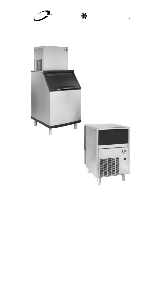
R Model
Flake & Nugget
Technician’s
Handbook
This manual is updated as new information and models
are released. Visit our website for the latest manual.
America’s #1 Selling Ice Machine
Part Number 000007661 6/13
www.manitowocice.com
Page 2

Page 3
Safety Notices
!
Warning
!
Caution
As you work on Manitowoc equipment, be sure to pay
close attention to the safety notices in this handbook.
Disregarding the notices may lead to serious injury
and/or damage to the equipment.
Throughout this handbook, you will see the following
types of safety notices:
Text in a Warning box alerts you to a potential
personal injury situation. Be sure to read the
Warning statement before proceeding, and work
carefully.
Text in a Caution box alerts you to a situation in
which you could damage the equipment. Be sure
to read the Caution statement before proceeding,
and work carefully.
Page 4

Procedural Notices
Important
As you work on Manitowoc equipment, be sure to read
the procedural notices in this handbook. These notices
supply helpful information which may assist you as
you work.
Throughout this handbook, you will see the following
types of procedural notices:
Text in an Important box provides you with
information that may help you perform a
procedure more efficiently. Disregarding this
information will not cause damage or injury, but it
may slow you down as you work.
NOTE: T ext set off as a Note provides you with simple,
but useful, extra information about the procedure you
are performing.
Page 5
Read These Before Proceeding:
!
Caution
Important
!
Warning
!
Warning
! Warning
Proper installation, care and maintenance are
essential for maximum performance and troublefree operation of your equipment. Visit our
website www.manitowocfsg.com for manual
updates, translations, or contact information for
service agents in your area.
Routine adjustments and maintenance
procedures outlined in this handbook are not
covered by the warranty.
Read this manual thoroughly before operating,
installing or performing maintenance on the
equipment. Failure to follow instructions in this
manual can cause property damage, injury or
death.
Do not use electrical appliances or accessories
other than those supplied by Manitowoc for your ice
machine model.
Two or more people or a lifting device are
required to lift this appliance.
Page 6
! Warning
This equipment contains high voltage electricity
! Warning
!
Warning
!
Warning
and refrigerant charge. Installation and repairs are
to be performed by properly trained technicians
aware of the dangers of dealing with high voltage
electricity and refrigerant under pressure.The
technician must also be certified in proper
refrigerant handling and servicing procedures. All
lockout and tag out procedures must be followed
when working on this equipment.
Do not damage the refrigeration circuit when
installing, maintaining or servicing the unit.
Do not operate equipment that has b een misused,
abused, neglected, damaged, or altered/modified
from that of original manufactured specifications.
This appliance is not intended for use by persons
(including children) with reduced physical, sensory
or mental capabilities, or lack of experience and
knowledge, unless they have been given
supervision concerning use of the appliance by a
person responsible for their safety. Do not allow
children to play with this appliance.
All covers and access panels must be in place
and properly secured, before operating this
equipment.
Page 7
!
Warning
Do not obstruct machine vents or openings.
! Warning
! Warning
! Warning
! Warning
Do not store gasoline or other flammable vapors
or liquids in the vicinity of this or any other
appliance.
Do not clean with water jet.
It is the responsibility of the equipment owner to
perform a Personal Protective Equipment Hazard
Assessment to ensure adequate protection
during maintenance procedures.
Two or more people are required to move this
equipment to prevent tipping.
Page 8
! Warning
When using electric appliances, basic
precautions must always be followed, including
the following:
a. Read all the instructions before using
the appliance.
b. To reduce the risk of injury, close
supervision is necessary when an
appliance is used near children.
c. Do not contact moving parts.
d. Only use attachments recommended or
sold by the manufacturer.
e. Do not use outdoors.
f. For a cord-connected appliance, the
following must be included:
• Do not unplug by pulling on cord. To
unplug, grasp the plug, not the cord.
• Unplug from outlet when not in use
and before servicing or cleaning.
• Do not operate any appliance with a
damaged cord or plug, or after the
appliance malfunctions or is dropped
or damaged in any manner. Contact
the nearest authorized service facility
for examination, repair, or electrical
or mechanical adjustment.
g. Follow applicable lock out tag out
procedures before working on
equipment.
h. Connect to a properly grounded outlet
only.
Page 9

Table of Contents
General Information
Model Numbers . . . . . . . . . . . . . . . . . . . . .15
Self Contained
Air & Water-Cooled Models . . . . . . . . .15
QuietQube Models with Remote
Condensing Units . . . . . . . . . . . . . . . .16
Rack Units . . . . . . . . . . . . . . . . . . . . . .16
Model/Serial Number . . . . . . . . . . . . . . . .17
Manitowoc Cleaner and Sanitizer . . . . . .17
Ice Machine Warranty Information . . . . .17
Installation
Installation Requirements . . . . . . . . . . . .19
Potable Water Requirements . . . . . . . . . .20
Drain Connections . . . . . . . . . . . . . . . . . .20
Ice Machine Clearance Requirements . .21
Cooling Tower Applications . . . . . . . . . .21
Electrical Service . . . . . . . . . . . . . . . . . . .22
Voltage . . . . . . . . . . . . . . . . . . . . . . . .22
Fuse/Circuit Breaker . . . . . . . . . . . . . . 22
Ground Fault Interrupter Circuit (GFIC) 22
Operation
Ice Making Sequence of Operation . . . . .23
RF0244/RNS0244/RF0266/RF0385/
RFS0385/RNS0385/RF0388/RF0399 . 23
RF0300 . . . . . . . . . . . . . . . . . . . . . . . .24
RFS0300/RNS0308 . . . . . . . . . . . . . .25
RF0644/RF0650/RF1200/RFS1200/
RF2300/RFS2300 . . . . . . . . . . . . . . . .26
RF1200C/RF2300C . . . . . . . . . . . . . .27
RF1200C/RF2300C . . . . . . . . . . . . . .28
RN0400 . . . . . . . . . . . . . . . . . . . . . . . .29
RN1000/RN1400 . . . . . . . . . . . . . . . . .36
RN1000C/RN1200C . . . . . . . . . . . . . .39
Thermostat Settings . . . . . . . . . . . . . . . . .43
Part Number 000007661 6/13 9
Page 10

Maintenance
Cleaning and Sanitizing . . . . . . . . . . . . . 45
Exterior Cleaning . . . . . . . . . . . . . . . . 45
RF/RFS/RNS Models Cleaning/Sanitizing
Procedures . . . . . . . . . . . . . . . . . . . . . 46
Parts removal for Cleaning/Sanitizing 52
Ice Chute Removal - RFS & RNS Models
. . . . . . . . . . . . . . . . . . . . . . . . . . . . . . 54
Ice Chute Removal - RF Models . . . . 56
Ice Chute Switch Actuator Removal . . 57
RN Models Cleaning/Sanitizing Procedure
. . . . . . . . . . . . . . . . . . . . . . . . . . . . . . 58
Cleaning the Air filter and Condenser . 60
Removal from Service/Winterization . . . 61
Troubleshooting
RF0244/RF0266/RF0385/RFS0385/RF0388/
RF0399 Troubleshooting . . . . . . . . . . . . . 63
Self-Contained Air-Cooled . . . . . . . . . 63
Electrical Diagnostic Flowchart . . . . . . 64
RF0300 Troubleshooting . . . . . . . . . . . . . 69
Self-Contained Air-Cooled . . . . . . . . . 69
Electrical Diagnostic Flowchart . . . . . . 70
RFS0300/RNS0308 Troubleshooting . . . 75
Self-Contained Air-Cooled . . . . . . . . . 75
Electrical Diagnostic Flowchart . . . . . . 76
RF0644/RF0650/RF1200/RFS1200
Troubleshooting . . . . . . . . . . . . . . . . . . . 81
Self-Contained Air-Cooled . . . . . . . . . 81
Rotation Sensor Operation . . . . . . . . . 81
Electrical Diagnostic Flowchart . . . . . . 82
RF1200C/RFS1200C Troubleshooting . . 87
QuietQube Remote Air-cooled Models with
Remote Condensing Unit . . . . . . . . . . 87
Electrical Diagnostic Flowchart . . . . . . 88
10 Part Number 000007661 6/13
Page 11

RF1200R/RFS1200R Troubleshooting . .94
Head Section For Rack Refrigeration
Systems . . . . . . . . . . . . . . . . . . . . . . .94
Rotation Sensor Operation . . . . . . . . .94
Electrical Diagnostic Flowchart . . . . . .95
RF2300/RFS2300 Troubleshooting . . . . .101
Self-Contained Air-Cooled . . . . . . . . . . 101
Rotation Sensor Operation . . . . . . . . .101
Electrical Diagnostic Flowchart . . . . . . 102
RF2300C/RFS2300C Troubleshooting . .108
QuietQube Remote Air-cooled Models with
Remote Condensing Unit . . . . . . . . . .108
Electrical Diagnostic Flowchart . . . . . . 109
RF2300R/RFS2300R Troubleshooting . .116
Head Section For Rack Refrigeration
systems . . . . . . . . . . . . . . . . . . . . . . . .116
Rotation Sensor Operation . . . . . . . . .116
Electrical Diagnostic Flowchart . . . . . . 117
RN0400 Troubleshooting . . . . . . . . . . . . .124
Over-Torque Failure . . . . . . . . . . . . . . 124
Water Loss Failure . . . . . . . . . . . . . . .127
Electrical Diagnostic Flowchart . . . . . . 128
RN1000/RN1400 Troubleshooting . . . . . . 133
Indicator Light Operation . . . . . . . . . . .133
Control Board Errors . . . . . . . . . . . . . .136
Electrical Diagnostic Flowchart . . . . . . 138
RN1000C/RN1200C Troubleshooting . . . 146
Indicator Light Operation . . . . . . . . . . .146
Control Board Errors . . . . . . . . . . . . . .149
Electrical Diagnostic Flowchart . . . . . 151
Refrigeration Troubleshooting . . . . . . . .161
Capillary Tube Models . . . . . . . . . . . . .161
Thermostatic Expansion Valve Models 162
Part Number 000007661 6/13 11
Page 12

Charts
Total System Refrigerant Charge . . . . . . 163
Ice Production & Refrigerant Pressure . 164
Flake Models . . . . . . . . . . . . . . . . . . . . . . 165
RF0244A & RFS0244 . . . . . . . . . . . . . 165
RF0266A . . . . . . . . . . . . . . . . . . . . . . 166
RF0300A & RFS0300A . . . . . . . . . . . 167
RF0385A . . . . . . . . . . . . . . . . . . . . . . 168
RF0388A . . . . . . . . . . . . . . . . . . . . . . 169
RF0399A . . . . . . . . . . . . . . . . . . . . . . 170
RF0644A . . . . . . . . . . . . . . . . . . . . . . 171
RF0650A & RFS0650 . . . . . . . . . . . . . 172
RF0650W . . . . . . . . . . . . . . . . . . . . . . 173
RF1200A & RFS1200A . . . . . . . . . . . 174
RF1200W & RFS1200W . . . . . . . . . . 175
RF1278C & RFS1278C With RCU1075 176
RF2300A . . . . . . . . . . . . . . . . . . . . . . 177
RF2300W . . . . . . . . . . . . . . . . . . . . . . 178
RF2378C & RFS2378C with RCU2375 179
Nugget Models . . . . . . . . . . . . . . . . . . . . . 180
RNS0244A . . . . . . . . . . . . . . . . . . . . . 180
RNS0308A . . . . . . . . . . . . . . . . . . . . . 181
RNS0385A . . . . . . . . . . . . . . . . . . . . . 182
RN0408A . . . . . . . . . . . . . . . . . . . . . . 183
RN1008A . . . . . . . . . . . . . . . . . . . . . . 184
RN1009W . . . . . . . . . . . . . . . . . . . . . . 185
RN1408A . . . . . . . . . . . . . . . . . . . . . . 186
RN1409W . . . . . . . . . . . . . . . . . . . . . . 187
RN1078C With RCU1075 . . . . . . . . . . 188
RN1278C With RCU1275 . . . . . . . . . . 189
Rack Models . . . . . . . . . . . . . . . . . . . . . . . 190
RF1279R . . . . . . . . . . . . . . . . . . . . . . 190
RFS1279R . . . . . . . . . . . . . . . . . . . . . 191
RF2379R . . . . . . . . . . . . . . . . . . . . . . 192
RFS2379R . . . . . . . . . . . . . . . . . . . . . 193
12 Part Number 000007661 6/13
Page 13

Diagrams
Wiring Diagrams . . . . . . . . . . . . . . . . . . . .195
Flake Models . . . . . . . . . . . . . . . . . . . . . . .196
RF0244/RNS0244/RF0266/RF0385/
RNS0385/RF0388/RF0399 Air-Cooled 196
RF0300 Air-Cooled . . . . . . . . . . . . . . .198
RFS0300 Air-Cooled . . . . . . . . . . . . . .200
RF0650/RF1200/RFS1200 Air-Cooled 202
RF1200/RFS1200 Water-Cooled . . . .204
RF1200C/RFS1200C QuietQube Head
Section . . . . . . . . . . . . . . . . . . . . . . . .206
RF2300/RFS2300 Air-Cooled & Water-
cooled . . . . . . . . . . . . . . . . . . . . . . . . .208
RF2378C/RFS2378C QuietQube Head
Section . . . . . . . . . . . . . . . . . . . . . . . .210
Condensing Units . . . . . . . . . . . . . . . . . . .212
RCU Condensing Unit 1ph . . . . . . . . . 212
RCU Condensing Unit 3ph . . . . . . . . . 213
Rack Models . . . . . . . . . . . . . . . . . . . . . . .214
RF1279R/RFS1279R Head Section . . 214
RF2379R/RFS2379R Head Section . . 216
Nugget Models . . . . . . . . . . . . . . . . . . . . .218
RNS0244/RNS0385 Air-Cooled . . . . .218
RNS0308 Air-Cooled . . . . . . . . . . . . . .220
RN0400 115v/60hz/1ph . . . . . . . . . . .222
RN0400 230v/60hz/1ph . . . . . . . . . . .223
RNS1000 Air-Cooled . . . . . . . . . . . . . .224
RN1000/RN1400 Air & Water Cooled .226
RN1000C/RN1200C QuietQube Head
Section . . . . . . . . . . . . . . . . . . . . . . . .227
Part Number 000007661 6/13 13
Page 14

Refrigeration Tubing Schematics . . . . . 228
Flake Models . . . . . . . . . . . . . . . . . . . . . . 228
RF0244/RFS0244/RF0266/RF0300/
RF0385/RF0388/RF0399/RF0644/RF0650
. . . . . . . . . . . . . . . . . . . . . . . . . . . . . . 228
RF1200/RFS1200 Air-cooled . . . . . . . 230
RF1200/RFS1200 Water-cooled . . . . 232
RF2300/RFS2300 Air-cooled . . . . . . . 234
RF2300/RFS2300 Water-cooled . . . . 236
RF1200C/RFS1200C QuietQube Head
Section & RCU1075 Condensing Unit 238
RF2300C/RFS2300 QuietQube Head
Section & RCU2375 Condensing Unit 240
Nugget Models . . . . . . . . . . . . . . . . . . . . . 242
RN0244/RNS0244/RN0385/RNS0385
Air & Water-cooled . . . . . . . . . . . . . . . 242
RNS0308 . . . . . . . . . . . . . . . . . . . . . . 244
RN0400/RN1000/RN1400 Air & Water-
cooled . . . . . . . . . . . . . . . . . . . . . . . . . 246
RN1000C/RN1200C QuietQube Head
Section & RCU1075/RCU1275 Condensing
Unit . . . . . . . . . . . . . . . . . . . . . . . . . . . 248
14 Part Number 000007661 6/13
Page 15
General Information
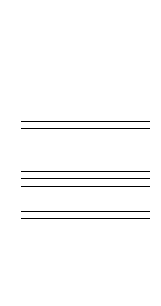
Model Numbers
SELF CONTAINED
AIR & WATER-COOLED MODELS
Flake Models
Self Storage
Air-Cooled
RF0244A – – –
RF0266A – – –
RF0385A – – –
RF0388A – – –
RF0399A – – –
– – RF0300A –
– – RFS0300A –
RF0644A – –
– – RF0650A RF0650W
– – RFS0650A RFS0650W
– – RF1200A RF1200W
– – RFS1200A RFS1200W
– – RF2300A RF2300W
Self Storage
Water-Cooled
Nugget Models
Self Storage
Air-Cooled
RNS0244A – – –
-- – RNS0308A –
RNS0385A – – –
RN0408A – – –
– – RNS1008A –
– – RN1008A RN1009W
– – RN1408A RN1409W
Self Storage
Water-Cooled
Modular
Air-Cooled
Modular
Air-Cooled
Modular
Water-
Cooled
Modular
Water-
Cooled
Part Number 000007661 6/13 15
Page 16
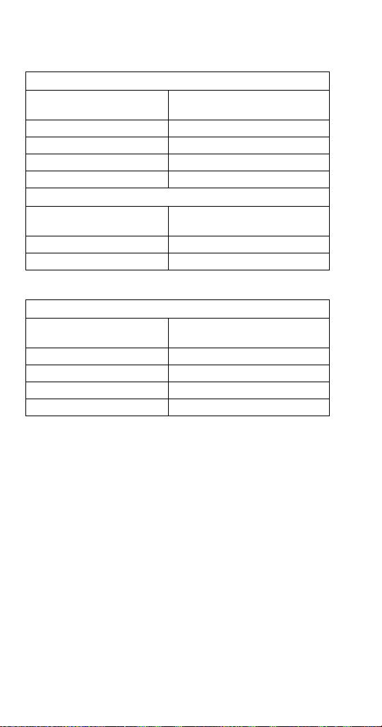
QUIETQUBE MODELS WITH REMOTE CONDENSING UNITS
Flake Models
QuietQube Head
RF1278C RCU1075
RFS1278C RCU1075
RF2378C RCU2375
RFS2378C RCU2375
RCU Remote
Condensing Unit
Nugget Models
QuietQube Head
RN1078C RCU1075
RN1278C RCU1275
RCU Remote
Condensing Unit
RACK UNITS
Flake Models
Head Section
RF1279R Supplied by Others
RFS1279R Supplied by Others
RF2379R Supplied by Others
RFS2379R Supplied by Others
Rack Remote
Condensing Unit
NOTE: Rack units share a common refrigeration circuit
with other equipment, such as display cases and glass
door freezer displays. Rack units have been modified
to function with rack systems and will not function
correctly with RCU condensing units.
16 Part Number 000007661 6/13
Page 17

Model/Serial Number
These numbers are required when requesting
information from your local Manitowoc Distributor, or
Manitowoc Ice. The model and serial number are
listed on the MODEL/SERIAL NUMBER DECAL
affixed to the ice machine.
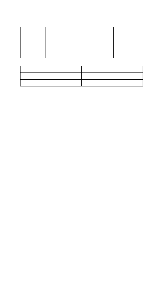
Manitowoc Cleaner and Sanitizer
Manitowoc Ice Machine Cleaner and Sanitizer are
available in 16 oz. (473 ml) bottles. These are the only
cleaner and sanitizer approved for use with Manitowoc
products.
Cleaner Part Number Sanitizer Part Number
16 oz. 000000084 16 oz. 9405653
1 gal N/A 1 gal. 9405813
Ice Machine Warranty Information
Warranty information for all ice machine models is
available on our website at www.manitowocice.com.
Part Number 000007661 6/13 17
Page 18

18 Part Number 000007661 6/13
This Page Intentionally Left Blan k
Page 19

Installation
Installation Requirements
The location selected for the ice machine must meet
the following criteria. If any of these criteria are not
met, select another location.
• Air temperature:
RF or RFS Flake Models - Minimum 50°F (10°C),
Maximum 110°F (43°C)
RN Nugget Models - Minimum 50°F (10°C),
Maximum 100°F (38°C)
RNS Nugget Models - Minimum 45°F (7°C),
Maximum 110°F (43°C)
• The location must be free of airborne and other
contaminants.
• The location must not be near heat-generating
equipment or in direct sunlight.
• The location must be capable of supporting the
weight of the ice machine and a full bin of ice.
• The location must allow enough clearance for
water, drain and electrical connections in the rear
of the ice machine.
• The location must not obstruct airflow through or
around the ice machine.
• The ice machine and bin must be level.
• Routine adjustments and maintenance procedures
outlined in this manual are not covered by the
warranty.
Part Number 000007661 6/13 19
Page 20

Potable Water Requirements
• Plumbing must conform to local codes.
• Water temperature: Minimum 40°F (4°C),
Maximum 90°F (32°C).
• Do not connect the ice machine to a hot water
supply. Be sure all hot water restrictors installed for
other equipment are working. (Check valves on
sink faucets, dishwashers, etc.)
• If water pressure exceeds maximum pressure
(70
psig [483 kPa] RN1000; 80 psig [552 kPa] for
all other models) obtain a water pressure regulator
from your Manitowoc distributor.
• A water shut-off valve is required to clean the ice
machine.
• A union for both the ice making and condenser
water lines is required.
• Water inlet lines require insulation to prevent
condensation.
• RF/RFS/RFN Models: A back flow preventer is
required on water inlet lines.
Drain Connections
• Drain lines must have a 1.5 inch drop per 5 feet of
run (2.5 cm per meter), and must not create traps.
• The floor drain must be large enough to
accommodate drainage from all drains.
• Bin drain termination must have an air gap.
• Separate insulated bin and water-cooled
condenser drain lines are required.
• The bin and ice machine drains require a vent.
20 Part Number 000007661 6/13
Page 21
Ice Machine Clearance Requirements
Head
Sections
Back 5" (12.7 cm) 5" (12.7 cm) 0" (0 cm)
Sides/Top 8" (20.3 cm) 8" (20.3 cm) 0" (20 cm)
* Water-Cooled Only - There is no minimum clearan ce required. This
value is recommended for efficient operation and servicing only.
Self-
Contained
Air-Cooled
RCU Units Remote Condensing Unit*
Front/Back 24" (61.0 cm)
Sides/Top 6" (15.2 cm)*
Self-
Contained
Water-Cooled*
QuietQube
Air-Cooled
NOTE: Allowance must be made for removal when the
ice machine is built-in. Monthly removal of the top
panel is required for cleaning and sanitizing.
Cooling Tower Applications
A water cooling tower installation does not require
modification of the ice machine. The water regulator
valve for the condenser continues to control the
refrigeration discharge pressure.
It is necessary to know the amount of heat rejection,
and pressure drop through the condenser and water
valves (inlet and outlet) when using a cooling tower on
an ice machine.
• Water entering the condenser must not be lower
than 37°F (3°C) or exceed 90°F (32°C).
• Water flow through the condenser must not
exceed 5 gal. (19 L) per minute.
• Allow for a pressure drop of 7 psi (48 kPa)
between the condenser water inlet and the outlet
of the ice machine.
• Water exiting the condenser must not exceed
110°F (43°C).
Part Number 000007661 6/13 21
Page 22
Electrical Service
!
Warning
!
Warning
All wiring must conform to local, state and national
codes.
VOLTAGE
The maximum allowable voltage variation is ± 10% of
the rated voltage on the ice machine model/serial
number plate at compressor start-up.
FUSE/CIRCUIT BREAKER
A separate fuse/circuit breaker must be provided for
each ice machine. Circuit breakers must be H.A.C.R.
rated (does not apply in Canada).
The ice machine must be grounded in accordance
with national and local electrical codes.
GROUND FAULT INTERRUPTER CIRCUIT (GFIC)
A GFCI/GFI circuit protection is not recommended
with our equipment. If a GFCI/GFI is required by code
a GFCI/GFI breaker rather than outlet must be used to
avoid intermittent nuisance trips.
22 Part Number 000007661 6/13
Page 23

Operation
Ice Making Sequence of Operation
NOTE: Flake ice machines use an auger to remove
ice from the evaporator. Occasional noises (creaks,
groans, squeaks, or pops) are a normal part of the ice
making process.
RF0244/RNS0244/RF0266/RF0385/RFS0385/ RNS0385/RF0388/RF0399
Self-Contained Air-Cooled
When the toggle switch is placed in the “ON” position
the following controls must be in the closed position
before the ice machine will start:
A. Bin Thermostat
B. Low Evaporator Temperature Thermostat
C. Low Water Level Switch
Placing the toggle switch in the ON position starts the
gear motor and refrigeration system. The float valve
controls the water inlet valve and water level. The
freeze cycle ends when ice contacts the bin
thermostat. The ice machine w ill restart when ice no
longer contacts the bin thermostat.
Part Number 000007661 6/13 23
Page 24

RF0300
Self-Contained Air-Cooled
When the toggle switch is placed in the “ON” position
the following controls must be in the closed position
before the ice machine will start:
A. Bin Thermostat
B. Ice Chute Safety Switch
C. Low Water Level Switch
D. Low Evaporator Temperature Thermostat
Placing the toggle switch in the ON position starts the
gear motor and a 10 minute compressor time delay.
The compressor starts and the float valve controls the
water inlet valve and water level. The freeze cycle
ends when ice contacts the bin thermostat. The ice
machine remains off until ice no longer contacts the
bin thermostat.
24 Part Number 000007661 6/13
Page 25

RFS0300/RNS0308
Self-Contained Air-Cooled
When the toggle switch is placed in the “ON” position
the following controls must be in the closed position
before the ice machine will start:
A. Bin Thermostat
B. Ice Chute Safety Switch
C. Low Water Level Switch
D. High Pressure Cut-out Switch
E. Low Pressure Cut-Out Switch
Placing the toggle switch in the ON position starts the
gear motor and a 10 minute compressor time delay.
The compressor starts and the float valve controls the
water inlet valve and water level. The freeze cycle
ends when ice contacts the bin thermostat. The ice
machine remains off until ice no longer contacts the
bin thermostat.
Part Number 000007661 6/13 25
Page 26

RF0644/RF0650/RF1200/RFS1200/RF2300/ RFS2300
Self-Contained Air-Cooled
When the toggle switch is placed in the ON position
the following controls must be in the closed position
before the ice machine will start:
A. Bin Thermostat
B. High Pressure Cut-out Switch
C. Ice Chute Safety Switch
D. Low Pressure Switch
E. Low Water Level Switch
Placing the toggle switch in the ON position starts the
gear motor. After the rotation speed sensor verifies
10 minutes of correct rotation the time delay ends and
the compressor starts.The ice machine will continue to
make ice until ice contacts the bin thermostat. The ice
machine remains off until ice no longer contacts the
bin thermostat.
26 Part Number 000007661 6/13
Page 27

RF1200C/RF2300C
QuietQube Remote Air-cooled Models with
Remote Condensing Unit
When the toggle switch is placed in the ON position
the following controls must be in the closed position
before the ice machine will start:
A. Bin Thermostat
B. High Pressure Cut-out Switch
C. Ice Chute Safety Switch
D. Low Pressure Switch
E. Low Water Level Switch
Placing the toggle switch in the ON position starts the
gear motor. After the rotation speed sensor verifies
10
minutes of correct rotation the time delay ends and
the liquid line solenoid valve opens.
• When the refrigerant pressure is high enough to
close the low-pressure control the contactor coil
energizes and the compressor starts.
• The refrigerant pressure will increase and close
the fan cycling pressure control and the condenser
fan motor starts.
The ice machine will continue to make ice until ice
contacts the bin thermostat and the liquid line solenoid
valve closes and the refrigeration system pumps
down.
• The refrigerant pressure drops and the fan cycling
pressure control opens stopping the condenser fan
motor.
• When the refrigerant pressure is low enough to
open the low pressure control, the contactor coil is
de-energized and the compressor stops.
The ice machine remains off until ice no longer
contacts the bin thermostat.
Part Number 000007661 6/13 27
Page 28

RF1200C/RF2300C
Head Section with Rack Refrigeration system
When the toggle switch is placed in the ON position
the following controls must be in the closed position
before the ice machine will start:
A. Bin Thermostat
B. Ice Chute Safety Switch
C. Low Water Level Switch
Placing the toggle switch in the ON position starts the
gear motor. After the rotation speed sensor verifies
10 minutes of correct rotation the time delay ends and
the liquid line and suction solenoid valves energize.
The ice machine will continue to make ice until ice
contacts the bin thermostat and the liquid line and
suction solenoid valves close.
The ice machine remains off until ice no longer
contacts the bin thermostat.
28 Part Number 000007661 6/13
Page 29

RN0400
Self-Contained Air-Cooled & Water-Cooled
NOTE: Ice machines use an auger to remove ice from
the evaporator. Occasional noises (creaks, groans,
squeaks, or pops) are a normal part of the ice making
process.
Operation
The ice machine will not start until:
A. The compressor rocker switch is moved to
“ON”.
B. Ice does not contact the bin thermostat bulb.
C. The water reservoir is full of water.
With power supplied and the compressor rocker
switch in the ON position, the gear motor and
refrigeration system start. The float valve controls the
water inlet valve and water level. The freeze cycle
ends when ice contacts the bin thermostat. A
20
minute delay period initiates. The ice machine will
restart when ice no longer contacts the bin thermostat
and the 20 minute delay period expires.
Part Number 000007661 6/13 29
Page 30
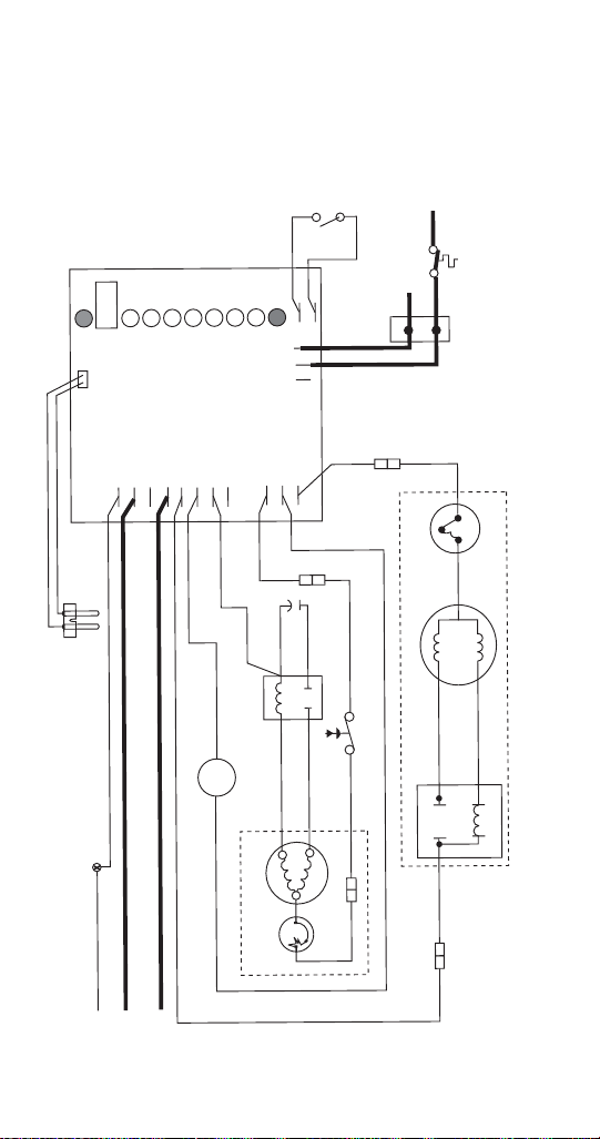
Step 1 Initial Startup
GRD
L1
L1
L2
L2
L2
L2
L2
COMPRESSOR
FA N
DRIVE
DR
C
20M
60M
2ND
WTR
B-T
B-E
RESET
GRD
G
B
W
FA N
BLACK
WHITE
BL
ACK
BLACK
R
ORANGE
S
S
L
COMPRESSOR
C
RED
BLACK
BLACK
WH
ITE
INPUT
POWER
WATER
SENSOR
CONTRO L
BOARD
K
C
A
LB
GEARMOTOR
24V
N
O
MM
O
C
C
A
V
E
N
I
L
RED
RED
WH
I
T
E
BIN T
-ST
A
T
W
HIT E
RED
WHITE
M
1
CO
MPRESSOR
SW
ITCH
PWR
BL
ACK
T
.
O.L.
BLACK
RED
HIGH PRESSURE
SAFETY SWITCH
4
2
3
RU N
START
T
.
O.L .
E
U
LB
YEL
L
O
W
BLACK
WHITE
M
BLA
CK
With power supplied to the control board the PWR
(power) light is energized. The bin thermostat closes
(BE light on) and the water level probe checks for
water.
30 Part Number 000007661 6/13
Page 31

Step 2 Gear Motor & Compressor Startup
GRD
L1
L1
L2
L2
L2
L2
L2
COMPRESSOR
FA N
DRIVE
DR
C
20M
60M
2ND
WTR
B-T
B-E
RESET
GRD
G
B
W
FA N
BLACK
WHITE
BL
ACK
BLACK
R
ORANGE
S
S
L
COMPRESSOR
C
RED
BLACK
BLACK
WHITE
INPUT
POWER
WATER
SENSOR
CONTRO L
BOARD
K
C
A
LB
GEARMOTOR
24V
N
O
MM
O
C
CA
V
E
N
I
L
RED
RED
WH
I
T
E
BIN T
-ST
A
T
W
HIT E
RED
WHITE
M
1
CO
MPRESSOR
SW
ITCH
PWR
BL
ACK
T
.
O.L.
BLACK
RED
HIGH PRESSURE
SAFETY SWITCH
4
2
3
RU N
START
T
.
O.L .
E
U
LB
YEL
L
O
W
BLACK
WH
ITE
M
BLA
CK
The WTR light energizes and the gear motor,
compressor and fan motor start.Two additional lights
energize DR (drive) and C (compressor).
Part Number 000007661 6/13 31
Page 32

Step 3 When the current to the compressor and gear
GRD
L1
L1
L2
L2
L2
L2
L2
COMPRESSOR
FA N
DRIVE
DR
C
20M
60M
2ND
WTR
B-T
B-E
RESET
GRD
G
B
W
FA N
BLACK
WHITE
BL
ACK
BLACK
R
ORANGE
S
S
L
COMPRESSOR
C
RED
BLACK
BLACK
WH
ITE
INPUT
POWER
WATER
SENSOR
CONTRO L
BOARD
K
C
A
LB
GEARMOTOR
24V
N
O
MM
O
C
CA
V
E
N
I
L
RED
RED
WH
I
T
E
BIN T-ST
A
T
W
HIT E
RED
WHITE
M
1
CO
MPRESSOR
SW
ITCH
PWR
BL
ACK
T
.
O.L.
BLACK
RED
HIGH PRESSURE
SAFETY SWITCH
4
2
3
RU N
START
T
.
O.L .
E
U
LB
YEL
L
O
W
BLACK
WH
ITE
M
BLA
CK
motor drops, the current relays open. The PWR, DR,
C, WTR and BE lights remain energized throughout
the freeze cycle.
32 Part Number 000007661 6/13
Page 33

Step 4 The bin/dispenser fills and the bin thermostat
GRD
L1
L1
L2
L2
L2
L2
L2
COMPRESSOR
FA N
DRIVE
DR
C
20M
60M
2ND
WTR
B-T
B-E
RESET
GRD
G
B
W
FA N
BLACK
WHITE
BL
ACK
BLACK
R
ORANGE
S
S
L
COMPRESSOR
C
RED
BLACK
BLACK
WHITE
INPUT
WATER
SENSOR
CONTRO L
BOARD
K
C
A
LB
GEARMOTOR
24V
N
O
MM
O
C
CA
V
E
N
I
L
RED
RED
WH
I
T
E
BIN T-STA
T
W
HIT E
RED
WHITE
M
1
CO
MPRESSOR
SW
ITCH
PWR
BL
ACK
T
.
O.L.
BLACK
RED
HIGH PRESSURE
SAFETY SWITCH
4
2
3
RU N
START
T
.
O.L .
E
U
LB
YEL
L
O
W
BLACK
WH
ITE
M
BLA
CK
opens. The BE light de-energizes and 10 seconds
later the BT light energizes and the C light deenergizes. The compressor and fan motor stop,
although the gear motor will run for an additional 60
seconds.
Part Number 000007661 6/13 33
Page 34

Step 5 The BT light is energized for 20 minutes to
GRD
L1
L1
L2
L2
L2
L2
L2
COMPRESSOR
FA N
DRIVE
DR
C
20M
60M
2ND
WTR
B-T
B-E
RESET
GRD
G
B
W
FA N
BLACK
WHITE
BL
ACK
BLACK
R
ORANGE
S
S
L
COMPRESSOR
C
RED
BLACK
BLACK
WH
ITE
INPUT
POWER
WATER
SENSOR
CONTRO L
BOARD
K
C
A
LB
GEARMOTOR
24V
N
O
MM
O
C
CA
V
E
N
I
L
RED
RED
WH
I
T
E
BIN T-STA
T
W
HIT E
RED
WHITE
M
1
CO
MPRESSOR
SW
ITCH
PWR
BL
ACK
T
.
O.L.
BLACK
RED
HIGH PRESSURE
SAFETY SWITCH
4
2
3
RU N
START
T
.
O.L .
E
U
LB
YEL
L
O
W
BLACK
WH
ITE
M
BLA
CK
indicate the machine is in the 20 minute time delay
period. Pressing the control board reset button
cancels the time delay.
34 Part Number 000007661 6/13
Page 35

Step 6 After 20 minutes the BT light de-energizes.
GRD
L1
L1
L2
L2
L2
L2
L2
COMPRESSOR
FA N
DRIVE
DR
C
20M
60M
2ND
WTR
B-T
B-E
RESET
GRD
G
B
W
FA N
BLACK
WHITE
BL
ACK
BLACK
R
ORANGE
S
S
L
COMPRESSOR
C
RED
BLACK
BLACK
WHITE
INPUT
POWER
WATER
SENSOR
CONTRO L
BOARD
K
C
A
LB
GEARMOTOR
24V
N
O
MM
O
C
CA
V
E
N
I
L
RED
RED
WH
I
T
E
BIN T
-ST
A
T
W
HIT E
RED
WHITE
M
1
CO
MPRESSOR
SW
ITCH
PWR
BL
ACK
T
.
O.L.
BLACK
RED
HIGH PRESSURE
SAFETY SWITCH
4
2
3
RU N
START
T
.
O.L .
E
U
LB
YEL
L
O
W
BLACK
WH
ITE
M
BLA
CK
The PWR and WTR lights remain energized. When
the bin thermostat closes the ice machine starts at
step 1.
Part Number 000007661 6/13 35
Page 36

RN1000/RN1400
Self-Contained Air-Cooled & Water-Cooled
NOTE: Ice machines use an auger to remove ice from
the evaporator. Occasional noises (creaks, groans,
squeaks, or pops) are a normal part of the ice making
process.
Operation
The ice machine will not start until:
A. The rocker switch is moved to ON.
B. The transport tube shuttle switch is closed.
C. The water reservoir is full of water.
Placing the toggle switch in the ON position starts the
gear motor and refrigeration system. The water level
sensor controls the water inlet valve and water level.
The freeze cycle ends when ice contact opens the
transport tube switch. A 60 minute time delay period
initiates. The ice machine will restart when the ice
transport tube switch closes and the 60 minute time
delay period expires.
Flush Cycle
The ice machine will automatically flush the
evaporator.
The refrigeration system will shut down and the gear
motor will continue to run. After the flush is complete,
the machine will refill and start the refrigeration system
without a time delay.
Continued on next page …
36 Part Number 000007661 6/13
Page 37

RN1000/RN1400 Indicator lights
ON OFF ON or OFF FLASHING
PURGE (Y)
POWER (G)
LOW BIN (G)
AUGER ON (G)
REFRIG ON (G)
CLEANING (Y)
SERVICE (R)
HI AMPS (R)
HI PRESS (R)
LO PRESS (R)
DRAIN CLOG (R)
TIME DELAY (Y)
LO WATER (R)
CPU (G)
HI WATER (R)
INDICATOR LIGHT LEGEND
• With line voltage supplied the green Power light is
on and the CPU light flashing a heartbeat indicates
the central processing unit is working.
• Yellow lights indicate normal off conditions.
• Red lights indicate an alarm condition.
The sequence below is for normally operating
machines. For alarm conditions refer to
troubleshooting which starts on page 133.
Step 1 Freeze cycle normal light operation
The CPU light flashes and the Refrigeration, Auger on,
Low bin and Power lights are on.
Part Number 000007661 6/13 37
Page 38

Step 2 Time delay cycle normal light operation
PURGE (Y)
POWER (G)
LOW BIN (G)
AUGER ON (G)
REFRIG ON (G)
CLEANING (Y)
SERVICE (R)
HI AMPS (R)
HI PRESS (R)
LO PRESS (R)
DRAIN CLOG (R)
TIME DELAY (Y)
LO WATER (R)
CPU (G)
HI WATER (R)
PURGE (Y)
POWER (G)
LOW BIN (G)
AUGER ON (G)
REFRIG ON (G)
CLEANING (Y)
SERVICE (R)
HI AMPS (R)
HI PRESS (R)
LO PRESS (R)
DRAIN CLOG (R)
TIME DELAY (Y)
LO WATER (R)
CPU (G)
HI WATER (R)
The bin fills with ice, the Low Bin light de-energizes
and the Time delay light energizes. The compressor
and gear motor immediately turn off and the
condenser fan continues to run for 10 minutes before
turning off. When the time delay ends and the Low bin
light energizes the ice machine will restart.
Step 3 Purge cycle normal light operation
After 1 to 2 hours of ice making the control board will
initiate a purge cycle. The compressor de-energizes
and the gear motor and condenser fan motor continue
to run. After the purge cycle is complete the ice
machine starts without a time delay period.
38 Part Number 000007661 6/13
Page 39

RN1000C/RN1200C
QuietQube Remote Air-cooled Model with Remote
Condensing Unit
NOTE: Ice machines use an auger to remove ice from
the evaporator. Occasional noises (creaks, groans,
squeaks, or pops) are a normal part of the ice making
process.
Operation
The ice machine will not start until:
A. The rocker switch is moved to ON.
B. The transport tube switch is closed.
C. The water reservoir is full of water.
Placing the toggle switch in the ON position starts the
gear motor and energizes the liquid line solenoid
valve. The refrigerant pressure at the condensing unit
increases and the low pressure switch closes and
starts the refrigeration system. The water level sensor
controls the water inlet valve and water level. The
freeze cycle ends when ice contact opens the
transport tube switch. The liquid line solenoid valve
closes and the refrigerant pressure at the condensing
unit drops. The low pressure switch opens and turns
off the refrigeration system. A 60
minute time delay
period initiates. The ice machine will restart when the
ice transport tube switch closes and the 60 minute
time delay period expires.
Part Number 000007661 6/13 39
Page 40

RN1000/RN1400 Indicator lights
ON OFF ON or OFF FLASHING
PURGE (Y)
POWER (G)
LOW BIN (G)
AUGER ON (G)
REFRIG ON (G)
CLEANING (Y)
SERVICE (R)
HI AMPS (R)
HI PRESS (R)
LO PRESS (R)
DRAIN CLOG (R)
TIME DELAY (Y)
LO WATER (R)
CPU (G)
HI WATER (R)
INDICATOR LIGHT LEGEND
• With line voltage supplied the green Power light is
on and the CPU light flashing a heartbeat indicates
the central processing unit is working.
• Yellow lights indicate normal off conditions.
• Red lights indicate an alarm condition.
The sequence below is for normally operating
machines. For alarm conditions refer to
troubleshooting which starts on page 133.
Step 1 Freeze cycle normal light operation
The CPU light flashes and the Refrigeration, Auger on,
Low bin and Power lights are on.
40 Part Number 000007661 6/13
Page 41

Step 2 Time delay cycle normal light operation
PURGE (Y)
POWER (G)
LOW BIN (G)
AUGER ON (G)
REFRIG ON (G)
CLEANING (Y)
SERVICE (R)
HI AMPS (R)
HI PRESS (R)
LO PRESS (R)
DRAIN CLOG (R)
TIME DELAY (Y)
LO WATER (R)
CPU (G)
HI WATER (R)
PURGE (Y)
POWER (G)
LOW BIN (G)
AUGER ON (G)
REFRIG ON (G)
CLEANING (Y)
SERVICE (R)
HI AMPS (R)
HI PRESS (R)
LO PRESS (R)
DRAIN CLOG (R)
TIME DELAY (Y)
LO WATER (R)
CPU (G)
HI WATER (R)
The bin fills with ice, the Low Bin light de-energizes
and the Time delay light energizes. The compressor
and gear motor immediately turn off and the
condenser fan continues to run for 10 minutes before
turning off. When the time delay ends and the Low bin
light energizes the ice machine will restart.
Step 3 Purge cycle normal light operation
After 1 to 2 hours of ice making the control board will
initiate a purge cycle. The compressor de-energizes
and the gear motor and condenser fan motor continue
to run. After the purge cycle is complete the ice
machine starts without a time delay period.
Part Number 000007661 6/13 41
Page 42

Ice Production/Quality Check
QUALITY CHECK
Ice quality varies with ambient and water
temperatures, and is measured by the amount of
water in the ice. Generally speaking, higher incoming
water temperature results in lower ice quality. Lower
water temperature results in higher ice quality.
ICE PRODUCTION CHECK
NOTE: Ice production checks that are within 10% of
the charted capacity are considered normal due to
variances in air and water temperatures. Actual
temperatures will seldom match the chart exactly.
1. Run the ice machine a minimum of 10 minutes to
allow the system to stabilize.
2. Catch the ice in a non-perforated container for
7
minutes and 12 seconds or for more accuracy
minutes and 24 seconds.
14
3. Weigh the container and ice, then deduct the
weight of the container.
4. Convert ounces to pounds.
5. Example: 3 lbs. 12 oz. converts to 3.75 lbs.
6. (12 oz. ÷ 16 oz. =.75 lb.)
7. Determine the 24-hour ice production capacity.
A. 7 minutes 12 seconds = Multiply the total ice
weight by 200.
B. 14 minutes 24 seconds = Multiply the total ice
weight by 100.
42 Part Number 000007661 6/13
Page 43

Thermostat Settings
1
2
3
4
5
6
7
1
2
3
4
5
6
7
Bin Thermostat
Small Numbers = Less ice in bin
Large Numbers = More ice in bin
Start at Chart Setting, then adjust as
required
Evaporator Low Temperature
Safety Thermostat
Refer to chart for setting
Incorrect settings will cause ice machine to
shut off prematurely
Bin Thermostat:
The bin thermostat sensing bulb is located in the ice
chute on modular models and in the bin thermostat
holder on the right side of the bin on self storage
models. The bin thermostat turns the ice machine on
and off as the level of ice in the bin changes. Use the
indicator on the ice machine label as the initial setting
and adjust as required.
Evaporator Low Temperature Safety Thermostat:
The evaporator low temperature safety thermostat
protects the ice machine if the evaporator temperature
is too cold. Refer to chart for correct setting.
Part Number 000007661 6/13 43
Page 44

Thermostat Setting Chart
NOTE: Settings are for reference only. Factory setting
is indicated on control label and overrides information
listed on this page.
Bin
Model
RF0244 5 5
RFS0244 5 6
RNS0244 5 5
RF0266 5 5
RF0300 4 7
RFS0300 3 N/A
RNS0308 3 6
RF0385 5 7
RNS0385 5 7
RF0388 5 7
RF0399 5 7
RF0644 5 N/A
RF0650 3 N/A
RFS0650 3 N/A
RF1200 4 N/A
RFS1200 3 N/A
RF2300 3 N/A
RFS2300 3 N/A
Thermostat
Setting
Evaporator
Thermostat
Setting
44 Part Number 000007661 6/13
Page 45

Maintenance
!
Caution
!
Warning
Cleaning and Sanitizing
Maintenance procedures covered in this manual are
not covered by the warranty.
Use only Manitowoc approved Ice Machine
Cleaner (part number 000000084) and Sanitizer
(part number 9405653). Do not mix Cleaner and
Sanitizer solutions together. It is a violation of
Federal law to use these solutions in a manner
inconsistent with their labeling. Read and
understand all labels printed on bottles before
use.
Wear rubber gloves and safety goggles (and/or
face shield) when handling ice machine Cleaner
or Sanitizer.
EXTERIOR CLEANING
Remove dust and dirt off exterior surfaces with mild
household dish-washing detergent and warm water.
Wipe dry with a clean, soft cloth.
Part Number 000007661 6/13 45
Page 46

RF/RFS/RNS MODELS CLEANING/SANITIZING PROCEDURES
Cleaning/Sanitizing Procedure
This procedure must be performed once every month.
• All ice must be removed from the bin
• The ice machine and bin must be disassembled
cleaned and sanitized
• The ice machine produces ice with the cleaner and
sanitizer solutions
• All ice produced during the cleaning and sanitizing
procedure must be discarded
Procedure to Clean/Sanitize
Use Ice Machine Cleaner part number 000000084.
Use Ice Machine Sanitizer part number 9405653.
Step 1 Remove front and top covers and set the
toggle switch to the OFF position.
Step 2 Remove all ice from the bin.
Step 3 Turn off the ice making water supply and drain
water from evaporator and reservoir.
Step 4 Remove the top cover from water reservoir.
Step 5 Follow the chart and premix cleaner and
water.
Amount of Water
1 gallon (4 Liters) 3 ounces (90 ml)
Amount of Cleaner
Part Number 000000084
46 Part Number 000007661 6/13
Page 47

Step 6 Fill the evaporator and reservoir with cleaning
Prop Float Up to Prevent Low
Water Level Shutdown
solution.
Step 7 Move the toggle switch to the ON position.
The ice machine will make ice with the cleaning
solution and deposit the ice in the bin. Add the
remaining cleaner/water solution as the water level in
the reservoir drops.
NOTE: Do not allow the cleaner/water level to drop
below the minimum water level. The ice machine will
discontinue the cleaning cycle if the water float switch
opens.
Step 8 After all of the cleaner/water solution has
been added turn on the ice making water supply.
Continue the freeze cycle for 10 minutes to remove
the cleaning solution from the water circuit.
Part Number 000007661 6/13 47
Page 48

Step 9 Place the toggle switch in the OFF position.
Step 10 Refer to disassembly for cleaning/sanitizing
and remove parts for hand cleaning/sanitizing.
• Hand clean all parts
• Rinse all parts with clear potable water
• Sanitize all parts - do not rinse after sanitizing
• Spray all interior bin surfaces with sanitizer (do not
rinse sanitized areas).
• Spray evaporator discharge spout
Step 11 Reassemble ice machine.
Step 12 Turn off the ice making water supply.
48 Part Number 000007661 6/13
Page 49

Step 13 Refer to chart and premix water and
sanitizer.
Amount of Water Amount of Sanitizer
1 Gallons (4 L) Water 1/2 ounce (15 ml)
Step 14 Fill the evaporator and reservoir with
sanitizer/water solution.
Step 15 Move the toggle switch to the ON positi on.
The ice machine will make ice with the sanitizer/water
solution and deposit the ice in the bin. Add the
remaining sanitizer/water solution when the water
level in the reservoir drops.
NOTE: Do not allow the sanitizer/water level to drop
below the minimum water level. The ice machine will
discontinue the cleaning cycle if the water float switch
opens.
Step 16 After all of the sanitizer/water solution has
been added to the reservoir, turn on the ice making
water supply.
Step 17 Continue the freeze cycle for 30 minutes and
then discard all ice produced.
Part Number 000007661 6/13 49
Page 50

Heavily Scaled Cleaning Procedure
Perform this procedure if you have some or all of these
symptoms.
• Excessive grinding, popping or squealing noises
from the evaporator
• Grinding noise from gearbox
• Ice machine trips speed sensor
NOTE: A Cleaning/Sanitizing Procedu re mu st be
performed after this procedure.
Procedure to Clean Heavily Scaled Flake Ice Machines
Step 1 Remove front and top covers and set the
toggle switch to the OFF position.
Step 2 Remove all ice from the bin.
Step 3 Turn off the ice making water supply.
Step 4 Remove the top cover from water reservoir.
50 Part Number 000007661 6/13
Page 51

Step 5 Refer to chart below:
Premix cleaner with lukewarm water in a
non-metallic container.
Mix Cleaner and Water
Use Ice machine nickel safe
cleaner, part number
000000084 only
Cleaner Water
Model
RF0244
RNS0244
RF0266
RNS0308
RF0385
RNS0385
RF0388
RF0399
RF0644
RF0300
RNS0308
RF0650
Water
Reservoir
Capacity
14 oz (400 ml) 9 oz (266 ml) 5 oz (148 ml)
17 oz (500 ml) 11 oz (325 ml) 6 oz (177 ml)
RF1200
RFS1200
RF2300
RFS2300
34 oz (1 L) 23 oz (680 ml) 11 oz (325 ml)
68 oz (2 L) 46 oz (1.3 L) 22 oz (650 ml)
Step 6 Remove all water from the evaporator and
water reservoir. Add the entire cleaner/water solution
and re-install the reservoir cover.
Leave the cleaner/water solution in the evaporator
for a minimum of 4 hours.
Step 7 Remove all cleaner/water from the evaporator
and water reservoir.
Step 8 Follow the standard cleaning and sanitizing
procedures.
Part Number 000007661 6/13 51
Page 52

PARTS REMOVAL FOR CLEANING/SANITIZING
!
Warning
!
Caution
Disconnect electric power to the ice machine at
the electric switch box and wear rubber gloves
and safety goggles (or face shield) while handling
cleaner or sanitizer.
Do not mix Cleaner and Sanitizer solutions
together. It is a violation of Federal law to use
these solutions in a manner inconsistent with
their labeling.
1. Turn off the water supply to the ice machine at the
water service valve.
2. Remove the components listed on the following
pages for cleaning and sanitizing.
3. Soak the removed part(s) in a properly mixed
solution of cleaner and water.
Solution Type Water Mixed With
Cleaner 1 gal. (4 L) 16 oz (500 ml) cleaner
Part Number 000000084
52 Part Number 000007661 6/13
Page 53

4. Use a soft-bristle brush or sponge (NOT a wire
brush) to carefully clean the parts.
5. Use the solution and a brush or sponge to clean
all disassembled components and the inside of
the bin.
6. Rinse all cleaned parts with clear water.
7. Mix a solution of sanitizer and water.
Solution Type Water Mixed With
Sanitizer 3 gal. (11 L) 2 oz (60 ml) sanitizer
Part Number 94-0565-3
8. Soak the parts in the sanitizer/water solution for
minutes. Use the sanitizer/water solution and a
10
sponge to sanitize all removed components and
the inside of the bin. Do not rinse the sanitized
parts.
9. Continue with step 11 of the cleaning/sanitizing
procedure.
Part Number 000007661 6/13 53
Page 54

ICE CHUTE REMOVAL - RFS & RNS MODELS
RFS0300/RNS0308/RFS1200/RFS2300
NOTE: A limited number of RF models have this type
of ice chute also.
1. Place the toggle switch in the OFF position, turn
off the water supply and disconnect electrical
power to the ice machine.
2. Disconnect water supply.
3. Remove water reservoir cover.
4. Remove microswitch and bin thermostat from the
ice chute.
5. Remove retainer, ice chute elbow and ice chute.
54 Part Number 000007661 6/13
Page 55

Part Number 000007661 6/13 55
Page 56

ICE CHUTE REMOVAL - RF MODELS
LOOSEN
SUPPORT BOLTS
TIP TOP OF ICE
CHUTE BACK AND
LIFT TO REMOVE
RF0300/RF0650/RF1200/RF2300
NOTE: A limited number of these models have the ice
chute listed on the previous page.
1. Place the toggle switch in the OFF position, turn
off the water supply and disconnect electrical
power to the ice machine.
2. Disconnect water supply.
3. Remove water reservoir cover.
4. Remove bin thermostat from ice chute.
5. Loosen bolts holding cross member.
6. Lift cross member and remove ice chute.
56 Part Number 000007661 6/13
Page 57

ICE CHUTE SWITCH ACTUATOR REMOVAL
INCORRECT REASSEMBLY CAN
RESULT IN AN ICE MACHINE
THAT WILL NOT RUN
RFS0300/RF0650/RF1200/RFS1200/RF2300/
RFS2300
1. Pull to remove nylon end cap.
2. Slide pin to remove.
3. Remove both sections of the pressure switch
bracket.
Part Number 000007661 6/13 57
Page 58

RN MODELS CLEANING/SANITIZING PROCEDURE
Use Ice Machine Cleaner part number 000000084.
Use Ice Machine Sanitizer part number 94-0565-3.
Step 1 Remove all ice from the bin/dispenser.
Step 2 Remove front and top covers.
Step 3 Mix a solution of cleaner and water.
Amount of
Luke Warm Water
1 gallon (4 Liters) 4 ounces (120 ml)
Amount of Cleaner
Part Number 000000084
Step 4 To start a cleaning cycle, depress the CLEAN
switch to drain the water from the evaporator. Wait for
the LOW WATER light to energize.
Step 5 Remove cover from the cleaning cup and add
cleaner/water solution until the HI WATER light
energizes, then replace cleaning cup cover. The
machine will clean and then flush three times in
approximately twelve minutes.
Step 6 While the ice machine is in the clean cycle,
prepare for the sanitizing cycle by mixing a solution of
sanitizer and water.
Amount of
Luke Warm Water
1 gallon (4 L) Water 1/2 ounce (15 ml)
Amount of Sanitizer
Part Number 94-0565-3
Step 7 To start a sanitize cycle, depress the clean
switch to drain the water from the evaporator. Wait for
the LOW WATER light to energize.
Step 8 Remove cover from the cleaning cup and add
sanitizer/water solution until the HI WATER light
energizes, then replace cleaning cup cover. The
machine will sanitize and then flush three times in
approximately twelve minutes.
58 Part Number 000007661 6/13
Page 59

Step 9 Press the OFF switch, then unscrew the ice
chute connector.
Step 10 Using disposable food service grade gloves
insert one dry sponge into the transport tube going to
the evaporator (NOT the tube going to the bin), then
insert one sponge soaked in the sanitizer water
solution. With the pusher tube supplied with the
sponge kit, push sponges all the way down the
transport tube 16 inches (41 cm) or the length of the
pusher tube.
Step 11 Reconnect chute connector and press the
ON switch. Allow the ice machine to run for 10
minutes, then press the OFF switch. Catch and
remove all sponges and ice from the bin/dispenser.
Step 12 Clean and sanitize the bin/dispenser :
• Disconnect power to the dispenser to prevent
injury.
• Use the cleaner and sanitizer ratios from the
charts on the previous page.
• Heavy accumulations of scale will require removal
of components for cleaning and sanitizing.
• Rinse parts with clear water after cleaning - do not
rinse parts after sanitizing.
Step 13 Spray all interior bin/dispenser surfaces with
sanitizer (do not rinse sanitized areas).
Step 14 Place rocker switch in the ON position and
reinstall all removed panels.
4. Lift out ice damper.
5. Remove ice deflector.
A. Remove the two thumbscrews.
Part Number 000007661 6/13 59
Page 60

CLEANING THE AIR FILTER AND CONDENSER
!
Warning
!
Warning
Disconnect electric power to the ice machine at the
electric service switch before cleaning the
condenser. The condenser fins are sharp. Use care
when cleaning them.
Air-Cooled Condenser
Clean the condenser at least every six months. Follow
the steps below.
1. Some models ha ve a washable filter. Clean the
filter with a mild soap and water solution.
2. Shine a flashlight through the condenser to check
for dirt between the fins. Blow compressed air
through the condenser fins from the inside or use
a commercial condenser coil cleaner. Follow the
directions and cautions supplied with the cleaner.
3. Straighten any bent condenser fins with a fin
comb.
4. Carefully wipe off the fan blades and motor with a
soft cloth. Do not bend the fan blades. If the fan
blades are excessively dirty, wash with warm,
soapy water and rinse thoroughly.
If you are cleaning the condenser fan blades with
water, cover the fan motor to prevent water damage.
60 Part Number 000007661 6/13
Page 61

Removal from Service/Winterization
!
Caution
If water is allowed to remain in the ice machine in
freezing temperatures, severe damage to some
components could result. Damage of this nature is
not covered by the warranty.
Follow the procedure below.
1. Disconnect the electric power at the circuit
breaker or the electric service switch.
2. Turn off the water supply.
3. Disconnect and drain the incoming ice-making
water line at the rear of the ice machine.
4. Disconnect drain tubing and drain water into
container and discard.
5. Make sure water is not trapped in any of the water
or drain lines.
6. Water cooled - Use compressed air to remove all
water from the condenser.
Part Number 000007661 6/13 61
Page 62

62 Part Number 000007661 6/13
This Page Intentionally Left Blan k
Page 63

Troubleshooting
Diagnostic troubleshooting for the ice machine
involves following flowcharts that are dependent on
symptoms of the failed machine.
Follow the flowcharts for the failure symptom and
model you are working on.
NOTE: Refer to the sequence of operation to
determine where in the sequence the ice machine has
failed. An example would be an ice machine that
energizes the gear motor, but the compressor does
not energize. Following the electrical flowchart will
quickly and easily eliminate non issues.
RF0244/RF0266/RF0385/RFS0385/ RF0388/RF0399 Troubleshooting
SELF-CONTAINED AIR-COOLED
Normal Operation
When the toggle switch is placed in the “ON” position
the following controls must be in the closed position
before the ice machine will start:
A. Bin Thermostat
B. Low Evaporator Temperature Thermostat
C. Low Water Level Switch
NOTE: Placing the toggle switch in the ON position
starts the gear motor and refrigeration system. The
float valve controls the water inlet valve and water
level. The freeze cycle ends when ice contacts the bin
thermostat. The ice machine w ill restart when ice no
longer contacts the bin thermostat.
Part Number 000007661 6/13 63
Page 64

64 Part Number 000007661 6/13
Power Supplied to Ice
Machine?
Toggle Switch In ON
Position?
Move Switch To ON Position
Plug In Ice Machine, Reset BreakerNO
YES
NO
YES
Electrical Flowchart - RF0244/RF0266/RF0385/RFS0385
RF0388/RF0399 AIR & WATER
Switch Illuminated?
NO
YES
Replace Switch
ELECTRICAL DIAGNOSTIC FLOWCHART
Page 65

Part Number 000007661 6/13 65
YES
Bin Thermostat
Closed?
NO
Replace Thermostat
Ice Contacting
Thermostat?
Remove Ice - Allow
To Warm And Retest
Adjusting Closes
Thermostat?
Verify New Setting Cycles
Machine On/Off
Yes
No No
Yes
Evaporator Safety
Thermostat Closed?
NO
Evaporator Cold?
Replace Thermostat
Allow Evaporator To
Warm And Retest
Adjusting Closes
Thermostat?
Verify New Setting Cycles
Machine On/Off
Yes
No
No
Yes
YES
YES
Page 66

66 Part Number 000007661 6/13
Low Water Level
Switch Closed?
YES
YES
NO
Reservoir Full Of
Water?
NO
Restore Water Supply / Replace Water Inlet Valve
Power To Water
Inlet Valve?
Yes
Water Level
Switch Closed?
No
No
Repair WiringYes
YES
Replace Switch or Float Assembly
Replace Switch or Float Assembly
Page 67

Part Number 000007661 6/13 67
Wiring From
Gearmotor Intact?
Line Voltage To
Compressor Relay
Coil?
Gear Motor Runs? NO
YES
NO
YES
Line Voltage To
Gear motor?
Repair WiringNo
Remove Auger
From Evaporator
Ice In Evaporator?
Gear Motor Runs?
Replace Gear Motor
Yes
No
Rebuild
Evaporator
Thaw Evaporator
Yes
Yes
No
Replace Gear Motor
Repair Wiring
Yes
No
Page 68

68 Part Number 000007661 6/13
Relay Closed?
Line Voltage To
Compressor?
YES
YES
NO
YES
NO
Verify:
Compressor Overload is Closed
Start Components Function
Fan Cycling Control Functions
Condenser Fan Motor Functions
Water cooled only:
Water Regulating Valve Functions
Repair Wiring
Replace Relay
Page 69

RF0300 Troubleshooting
SELF-CONTAINED AIR-COOLED
Normal Operation
When the toggle switch is placed in the “ON” position
the following controls must be in the closed position
before the ice machine will start:
A. Bin Thermostat
B. Low Evaporator Temperature Thermostat
C. Ice Chute Safety Switch
D. Low Water Level Switch
Placing the toggle switch in the ON position starts the
gear motor and a 10 minute compressor time delay.
The compressor starts and the float valve controls the
water inlet valve and water level. The freeze cycle
ends when ice contacts the bin thermostat. The ice
machine remains off until ice no longer contacts the
bin thermostat.
Part Number 000007661 6/13 69
Page 70

70 Part Number 000007661 6/13
Power Supplied to Ice
Machine?
Toggle Switch In ON
Position?
Move Switch To ON Position
Plug In Ice Machine, Reset BreakerNO
YES
NO
YES
Electrical Flowchart - RF0300
Switch Illuminated?
NO
YES
Replace Switch
ELECTRICAL DIAGNOSTIC FLOWCHART
Page 71

Part Number 000007661 6/13 71
Bin Thermostat
Closed?
NO
Replace Thermostat
YES
Evaporator Safety
Thermostat Closed?
NO
Chute Switch
Closed?
NO
YES
Ice Contacting
Thermostat?
Remove Ice - Allow
To Warm And Retest
Adjusting Closes
Thermostat?
Verify New Setting Cycles
Machine On/Off
Yes
No No
Yes
Evaporator Cold?
Replace Thermostat
Allow Evaporator To
Warm And Retest
Adjusting Closes
Thermostat?
Verify New Setting Cycles
Machine On/Off
Yes
No
No
Yes
Adjust Or Replace
Actuator
Ice Contacting
Actuator?
Remove Ice And
Retest
Actuator Functions?
Replace Switch
Yes
No No
Yes
Yes
Yes
Page 72

72 Part Number 000007661 6/13
Low Water Level
Switch Closed?
YES
YES
NO
Reservoir Full Of
Water?
NO
Restore Water Supply / Replace Water Inlet Valve
Replace Switch or Float Assembly
Power To Water
Inlet Valve?
Yes
Water Level
Switch Closed?
No
No
Repair WiringYes
YES
Replace Switch or Float Assembly
Page 73

Part Number 000007661 6/13 73
Gear Motor Runs? NO
YES
Line Voltage To
Gear motor?
Repair WiringNo
Disconnect
Evaporator From
Gear Motor
Ice In Evaporator?
Gear Motor Runs?
Replace Gear Motor
Yes
No
Rebuild
Or
Replace Evaporator
Thaw Evaporator
Yes
Yes
No
Yes
Gear Motor
Centrifugal Switch
Closed?
Line Voltage To
Compressor Time
Delay?
NO
Repair Wiring
Replace Gear Motor
Yes
No
YES
Page 74

74 Part Number 000007661 6/13
Contactor Closed?
Line Voltage To
Compressor?
YES
YES
NO
YES
NO
Verify:
Compressor Overload is Closed
Start Components Function
Fan Cycling Control Functions
Condenser Fan Motor Functions
Water cooled only:
Water Regulating Valve Functions
Repair Wiring
Replace Contactor
Line Voltage To
Compressor Contactor
Coil?
NO
Repair Wiring
Replace Time Delay Relay
No
10 Minute Time
Delay Expired?
NO
Wait 10 Minutes - Do Not Install
Compressor Time Delay Jumper
Yes
Power To Contactor Coil?
Yes
Install
Compressor Time
Delay Jumper
Yes
Page 75

RFS0300/RNS0308 Troubleshooting
SELF-CONTAINED AIR-COOLED
When the toggle switch is placed in the “ON” position
the following controls must be in the closed position
before the ice machine will start:
A. Bin Thermostat
B. Ice Chute Safety Switch
C. Low Water Level Switch
D. High Pressure Cut-out Switch
E. Low Pressure Cut-Out Switch
Placing the toggle switch in the ON position starts the
gear motor and a 10 minute compressor time delay.
The compressor starts and the float valve controls the
water inlet valve and water level. The freeze cycle
ends when ice contacts the bin thermostat. The ice
machine remains off until ice no longer contacts the
bin thermostat.
Part Number 000007661 6/13 75
Page 76

76 Part Number 000007661 6/13
Power Supplied to Ice
Machine?
Toggle Switch In ON
Position?
Move Switch To ON Position
Plug In Ice Machine, Reset BreakerNO
YES
NO
YES
Electrical Flowchart - RF603005)6
Switch Illuminated?
NO
YES
Replace Switch
ELECTRICAL DIAGNOSTIC FLOWCHART
Page 77

Part Number 000007661 6/13 77
Bin Thermostat
Closed?
NO
Replace Thermostat
YES
/RZ3UHVVXUH
6ZLWFK Closed?
NO
Chute Switch
Closed?
NO
YES
Ice Contacting
Thermostat?
Remove Ice - Allow
To Warm And Retest
Adjusting Closes
Thermostat?
Verify New Setting Cycles
Machine On/Off
Yes
No No
Yes
Evaporator Cold?
Replace /3&2
Allow Evaporator To
Warm And Retest
5HIULJHUDQW3UHVVXUH
%HORZ&XWRXW?
5HSDLU5HIULJHUDQW/HDN
(YDFXDWH5HFKDUJH
Yes
No
No
Yes
Adjust Or Replace
Actuator
Ice Contacting
Actuator?
Remove Ice And
Retest
Actuator Functions?
Replace Switch
Yes
No No
Yes
Yes
Yes
Page 78

78 Part Number 000007661 6/13
Low Water Level
Switch Closed?
YES
YES
NO
Reservoir Full Of
Water?
NO
Restore Water Supply / Replace Water Inlet Valve
Replace Switch or Float Assembly
Power To Water
Inlet Valve?
Yes
Water Level
Switch Closed?
No
No
Repair WiringYes
YES
Replace Switch or Float Assembly
Page 79

Part Number 000007661 6/13 79
Gear Motor Runs? NO
YES
Line Voltage To
Gear motor?
Repair WiringNo
Disconnect
Evaporator From
Gear Motor
Ice In Evaporator?
Gear Motor Runs?
Replace Gear Motor
Yes
No
Rebuild
Or
Replace Evaporator
Thaw Evaporator
Yes
Yes
No
Yes
Gear Motor
Centrifugal Switch
Closed?
Line Voltage To
Compressor Time
Delay?
NO
Repair Wiring
Replace Gear Motor
Yes
No
YES
Page 80

80 Part Number 000007661 6/13
Contactor Closed?
Line Voltage To
Compressor?
YES
YES
NO
YES
NO
Verify:
Compressor Overload is Closed
Start Components Function
Fan Cycling Control Functions
Condenser Fan Motor Functions
Water cooled only:
Water Regulating Valve Functions
Repair Wiring
Replace Contactor
Line Voltage To
Compressor Contactor
Coil?
NO
Repair Wiring
Replace Time Delay Relay
No
10 Minute Time
Delay Expired?
NO
Wait 10 Minutes - Do Not Install
Compressor Time Delay Jumper
Yes
Power To Contactor Coil?
Yes
Install
Compressor Time
Delay Jumper
Yes
Page 81

RF0644/RF0650/RF1200/RFS1200 Troubleshooting
SELF-CONTAINED AIR-COOLED
Normal Operation
When the toggle switch is placed in the ON position
the following controls must be in the closed position
before the ice machine will start:
A. Bin Thermostat
B. High Pressure Cut-out Switch
C. Ice Chute Safety Switch
D. Low Pressure Switch
E. Low Water Level Switch
NOTE: Placing the toggle switch in the ON position
starts the gear motor. After the rotation speed sensor
verifies 10
ends and the compressor starts.The ice machine will
continue to make ice until ice contacts the bin
thermostat. The ice machine re ma ins off until ice no
longer contacts the bin thermostat.
ROTATION SENSOR OPERATION
Yellow Blinking Tim e Delay Period
minutes of correct rotation the time delay
light Definition
Yellow Solid Normal Operation Sensing
Red Blinking Fault Time Delay Period
Red Solid
Lockout - 8 Consecutive Faults
Remove/Restore Power To Reset
Part Number 000007661 6/13 81
Page 82

82 Part Number 000007661 6/13
Power Supplied to Ice
Machine?
Toggle Switch In ON
Position?
Move Switch To ON Position
Plug In Ice Machine, Reset BreakerNO
YES
NO
YES
Electrical Flowchart – RF0644/RF0650/RF1200/RFS1200
AIR & WATER
Switch Illuminated?
NO
YES
Replace Switch
ELECTRICAL DIAGNOSTIC FLOWCHART
Page 83

Part Number 000007661 6/13 83
Bin Thermostat
Closed?
NO
Replace Thermostat
YES
Low Pressure
Control Closed?
NO
YES
Ice Contacting
Thermostat?
Remove Ice - Allow
To Warm And Retest
Adjusting Closes
Thermostat?
Verify New Setting Cycles
Machine On/Off
Yes
No No
Yes
Evaporator Cold?
Replace LPCO
Allow Evaporator To
Warm And Retest
Refrigerant Pressure
Below Cut-out?
Repair Refrigerant Leak,
Evacuate, Recharge
Yes
No
No
Yes
Yes
High Pressure
Control Closed?
NO
YES
Resets?
Replace HPCO
Clean Condenser,
Check Fan Motor
Check Fan Cycle Control
Refrigerant Pressure
Above Cut-out?
Clean Condenser,
Check Fan Motor,
Check FCC & Refrigeration System
Resets
&
Trips
No
No
Yes
Page 84

84 Part Number 000007661 6/13
Low Water Level
Switch Closed?
YES
NO
Reservoir Full Of
Water?
NO
Restore Water Supply / Replace Water Inlet Valve
Replace Switch or Float Assembly
Power To Water
Inlet Valve?
Yes
Water Level
Switch Closed?
No No
Repair WiringYes
YES
Replace Switch or Float Assembly
Chute Switch
Closed?
NO
Adjust Or Replace
Actuator
Ice Contacting
Actuator?
Remove Ice And
Retest
Actuator Functions?
Replace Switch
Yes
No No
Yes
Yes
YES
Page 85

Part Number 000007661 6/13 85
Gear Motor Runs? NO
YES
Line Voltage To
Gear motor?
Repair Wiring
No
Disconnect
Evaporator From
Gear Motor
Ice In Evaporator?
Gear Motor Runs?
Replace Gear Motor
Yes
No
Rebuild
Or
Replace Evaporator
Thaw Evaporator
Yes
Yes
No
Yes
YES
10 Minute Time
Delay Expired?
NO
Wait 10 Minutes - Do Not Install
Compressor Time Delay Jumper
Page 86

86 Part Number 000007661 6/13
Contactor Closed?
Line Voltage To
Compressor?
YES
YES
NO
YES
NO
Verify:
Compressor Overload is Closed
Start Components Function
Fan Cycling Control Functions
Condenser Fan Motor Functions
Water cooled only:
Water Regulating Valve Functions
Repair Wiring
Replace Contactor
Line Voltage To
Compressor Contactor
Coil?
NO
Repair Wiring
Replace Rotation Sensor/Time Delay Relay
No
Yes
Power To Contactor Coil?
Yes
Install
Compressor Time
Delay Jumper
Page 87

RF1200C/RFS1200C Troubleshooting
QUIETQUBE REMOTE AIR-COOLED MODELS WITH REMOTE CONDENSING UNIT
Normal Operation
When the toggle switch is placed in the ON position
the following controls must be in the closed position
before the ice machine will start:
A. Bin Thermostat
B. High Pressure Cut-out Switch
C. Ice Chute Safety Switch
D. Low Pressure Switch
E. Low Water Level Switch
Placing the toggle switch in the ON position starts the
gear motor. After the rotation speed sensor verifies
10 minutes of correct rotation the time delay ends and
the liquid line solenoid valve opens.
• When the refrigerant pressure is high enough to
close the low-pressure control the contactor coil
energizes and the compressor starts.
• The refrigerant pressure will increase and close
the fan cycling pressure control and the condenser
fan motor starts.
The ice machine will continue to make ice until ice
contacts the bin thermostat and the liquid line solenoid
valve closes and the refrigeration system pumps
down.
• The refrigerant pressure drops and the fan cycling
pressure control opens stopping the condenser fan
motor.
• When the refrigerant pressure is low enough to
open the low pressure control, the contactor coil is
de-energized and the compressor stops.
NOTE: The ice machine remains off until ice no longer
contacts the bin thermostat.
Part Number 000007661 6/13 87
Page 88

88 Part Number 000007661 6/13
Power Supplied
to Ice Machine?
Toggle Switch In
ON Position?
Move Switch To ON Position
Restore Power, Reset BreakerNO
NO
YES
(OHFWULFDO)ORZFKDUW 5)&5)6&4XLHW4XEH
Switch
Illuminated?
NO
YES
Replace Switch
Immediately
Trips?
YES
YES
NO
Toggle Switch In
Off Position?
Isolate And Ohm Each
Component - Then Each
Wire If Required
NO
TRIPS
YES
Isolate And Ohm Switch
Check Wiring From Panel
Test Run
YES
ELECTRICAL DIAGNOSTIC FLOWCHART
Page 89

Part Number 000007661 6/13 89
Bin Thermostat
Closed?
NO
Replace Thermostat
YES
Ice Contacting
Thermostat?
Remove Ice - Allow
To Warm And Retest
Adjusting Closes
Thermostat?
Verify New Setting Cycles
Machine On/Off
YES
NO NO
YES
YES
Chute Switch
Closed?
NO
Adjust Or Replace
Actuator
Ice Contacting
Actuator?
Remove Ice And
Retest
Actuator Functions?
Replace SwitchYES
NO NO
YES
Yes
YES
Reservoir Full Of
Water?
NO
Restore Water Supply / Replace Water Inlet Valve
Power To Water
Inlet Valve?
YES
Water Level
Switch Closed?
NO NO
Repair Wiring
Replace Switch or
Float Assembly
YES
Page 90

90 Part Number 000007661 6/13
Low Water Level
Switch Closed?
NO
Replace Switch or
Float Assembly
Gear Motor Runs? NO
Line Voltage To
Gear motor?
Repair WiringNO
Disconnect
Evaporator From
Gear Motor
Gear Motor
Runs?
Replace Gear Motor
YES
NO
YES
YES
Ice In
Evaporator?
Rebuild
Or
Replace Evaporator
Thaw EvaporatorYES
NO
YES
YES
YES
10 Minute Time
Delay Expired?
NO
Wait 10 Minutes - Do Not Install
Compressor Time Delay Jumper
Page 91

Part Number 000007661 6/13 91
YES
NO
Replace Relay
NO
Repair Wiring
Replace Rotation
Sensor/Time Delay
NO
Power To Left Time
Delay Relay Coil?
Install
Compressor Time
Delay Jumper On
Left Evaporator
Delay Relay Contacts
Closed?
Delay Relay Contacts
Closed?
Yes
NO
YES
YES
Line Voltage To
Left Delay Relay Coil?
YES
Replace Relay
Page 92

92 Part Number 000007661 6/13
Low Pressure
Control Closed?
Line Voltage At
Liquid Line Solenoid
Valve?
NO
NO
YES
Verify:
Refrigerant Pressure is Higher Than
LPCO Cut-in
Both Shut-off Valves are Open
Repair/Replace Liquid Line Solenoid
Locate and Repair Refrigerant Leak
Replace LPCO Switch
Replace Relay
YES
High Pressure
Control Closed?
NO Resets?
Replace HPCO
Clean Condenser,
Check Fan Motor
Check Fan Cycle Control
Refrigerant Pressure
Above Cut-out?
Clean Condenser,
Check Fan Motor,
Check Fan Cycle Control &
Refrigeration System
Resets
&
Trips
NO NO
YES
NO
Line Voltage To
Compressor
Contactor Coil?
YES
YES
YES
Repair Wiring
Page 93

Part Number 000007661 6/13 93
Contactor
Closed?
NO
Replace Contactor
Line Voltage To
Compressor?
YES
YES
NO
Verify:
Compressor Overload is Closed
Start Components Function
Fan Cycling Control Functions
Condenser Fan Motor Functions
Repair Wiring
YES
Page 94

RF1200R/RFS1200R Troubleshooting
HEAD SECTION FOR RACK REFRIGERATION SYSTEMS
Normal Operation
When the toggle switch is placed in the ON position
the following controls must be in the closed position
before the ice machine will start:
A. Bin Thermostat
B. Ice Chute Safety Switch
C. Low Water Level Switch
Placing the toggle switch in the ON position starts the
gear motor. After the rotation speed sensor verifies
10
minutes of correct rotation the time delay ends and
the liquid line and suction solenoid valves energize.
The ice machine will continue to make ice until ice
contacts the bin thermostat and the liquid line and
suction solenoid valves close.
The ice machine remains off until ice no longer
contacts the bin thermostat.
ROTATION SENSOR OPERATION
light Definition
Yellow Blinking Tim e Delay Period
Yellow Solid Normal Operation Sensing
Red Blinking Fault Time Delay Period
Red Solid
Lockout - 8 Consecutive Faults
Remove/Restore Power To Reset
94 Part Number 000007661 6/13
Page 95

Part Number 000007661 6/13 95
Power Supplied
to Ice Machine?
Toggle Switch In
ON Position?
Move Switch To ON Position
Restore Power, Reset BreakerNO
NO
YES
Electrical Flowchart – RF1200R/RFS1200R
Switch
Illuminated?
NO
YES
Replace Switch
Immediately
Trips?
Yes
Ohm Toggle Switch, Time
Delays, Gear Motors,
Water Inlet Valve
Yes
No
Toggle Switch In
Off Position?
Isolate And Ohm Each
Component - Then Each
Wire If Required
Yes
No
Trips
ELECTRICAL DIAGNOSTIC FLOWCHART
Page 96

96 Part Number 000007661 6/13
Bin Thermostat
Closed?
NO
Replace Thermostat
YES
Ice Contacting
Thermostat?
Remove Ice - Allow
To Warm And Retest
Adjusting Closes
Thermostat?
Verify New Setting Cycles
Machine On/Off
Yes
No No
Yes
Yes
Chute Switch
Closed?
NO
Adjust Or Replace
Actuator
Ice Contacting
Actuator?
Remove Ice And
Retest
Actuator Functions?
Replace Switch
Yes
No No
Yes
Yes
Page 97

Part Number 000007661 6/13 97
YES
Reservoir Full Of
Water?
NO
Restore Water Supply / Replace Water Inlet Valve
Power To Water
Inlet Valve?
Yes
Float Switch
Closed?
No
No
Repair Wiring
Replace Switch or Float Assembly
Yes
Low Water Level
Switch Closed?
NO
Replace Switch or Float Assembly
YES
Yes
Page 98

98 Part Number 000007661 6/13
Gear Motor Runs? NO
YES
Line Voltage To
Gear motor?
Repair WiringNo
Disconnect
Evaporator From
Gear Motor
Ice In Evaporator?
Gear Motor Runs?
Replace Gear Motor
Yes
No
Rebuild
Or
Replace Evaporator
Thaw Evaporator
Yes
Yes
No
YES
10 Minute Time
Delay Expired?
NO
Wait 10 Minutes - Do Not Install
Compressor Time Delay Jumper
YES
Page 99

Part Number 000007661 6/13 99
YES
NO
Replace Relay
Line Voltage To
Delay Relay Coil?
NO
Repair Wiring
Replace Rotation
Sensor/Time Delay
No
Power To Time
Delay Relay Coil?
Install
Compressor Time
Delay Jumper
Delay Relay
Contacts Closed?
Delay Relay
Contacts Closed?
Yes
No Yes
YES
YES
YES
Line Voltage To
Contactor Coil?
NO Repair Wiring
YES
Contactor Closed?
NO
Replace Contactor
Page 100

100 Part Number 000007661 6/13
YES
Line Voltage To
Suction Line Solenoid?
YES
NO
Check Contactor Contacts On Both Contactors
Repair Wiring
Line Voltage To Liquid
Line Solenoid?
YES
NO
Repair Wiring
Determine Refrigeration System Issue
Suction And Liquid Line
Solenoid Valves Open?
YES
NO
Replace Defective Valve
 Loading...