

Page 1

Q Model
QuietQube
® Ice Machines
with CVD® Technology
Models Q0600C/Q0800C/Q1000C
Q1400C/QDUALC
IB0600C/IB0800C/IB1000C
Service
Manual
Thank you for selecting a Manitowoc Ice Machine, the dependability leader in ice making equipment and related products.
With proper installation, care and maintenance, your new Manitowoc Ice Machine will provide you with many years of
reliable and economical performance.
This manual is updated as new information and models
are released. Visit our website for the latest manual.
www.manitowocice.com
Part Number 80-1206-3
5/2005
Page 2

Safety Notices
Procedural Notices
As you work on a QuietQube®-Series Ice Machine, be
sure to pay close attention to the safety notices in this
manual. Disregarding the notices may lead to serious
injury and/or damage to the ice machine.
Throughout this manual, you will see the following types
of safety notices:
!
Warning
PERSONAL INJURY POTENTIAL
Do not operate equipment that has been misused,
abused, neglected, damaged, or altered/modified
from that of original manufactured specifications.
Warning
!
Text in a Warning box alerts you to a potential
personal injury situation. Be sure to read the
Warning statement before proceeding, and work
carefully.
Caution
!
Text in a Caution box alerts you to a situation in
which you could damage the ice machine. Be sure
to read the Caution statement before proceeding,
and work carefully.
As you work on a QuietQube®-Series Ice Machine, be
sure to read the procedural notices in this manual.
These notices supply helpful information which may
assist you as you work.
Throughout this manual, you will see the following types
of procedural notices:
Important
Text in an Important box provides you with
information that may help you perform a procedure
more efficiently. Disregarding this information will
not cause damage or injury, but it may slow you
down as you work.
NOTE: Text set off as a Note provides you with simple,
but useful, extra information about the procedure you
are performing.
Read These Before Proceeding:
Caution
!
Proper installation, care and maintenance are
essential for maximum ice production and troublefree operation of you Manitowoc Ice Machine.
Read and understand this manual. It contains
valuable care and maintenance information. If you
enounter problems not covered by this manual, do
not proceed, contact Manitowoc Ice, Inc. We will be
happy to provide assistance.
Important
Routine adjustments and maintenance procedures
outlined in this manual are not covered by the
warranty.
We reserve the right to make product improvements at any time.
Specifications and design are subject to change without notice.
Page 3

Section 1
General Information
Model Numbers . . . . . . . . . . . . . . . . . . . . . . . . . . . . . . . . . . . . . . . . . . . . . . . . . . 1-1
How to Read a Model Number . . . . . . . . . . . . . . . . . . . . . . . . . . . . . . . . . . . . . . 1-1
Remote Condensing Unit . . . . . . . . . . . . . . . . . . . . . . . . . . . . . . . . . . . . . . . . . . 1-1
Ice Cube Sizes . . . . . . . . . . . . . . . . . . . . . . . . . . . . . . . . . . . . . . . . . . . . . . . . . . . 1-1
Model/Serial Number Location . . . . . . . . . . . . . . . . . . . . . . . . . . . . . . . . . . . . . . 1-2
Owner Warranty Registration Card . . . . . . . . . . . . . . . . . . . . . . . . . . . . . . . . . . 1-3
Warranty Coverage . . . . . . . . . . . . . . . . . . . . . . . . . . . . . . . . . . . . . . . . . . . . . . . 1-3
Section 2
Installation Instructions
Ice Machine Dimensions . . . . . . . . . . . . . . . . . . . . . . . . . . . . . . . . . . . . . . . . . . . 2-1
Condensing Unit Dimensions . . . . . . . . . . . . . . . . . . . . . . . . . . . . . . . . . . . . . . 2-3
Location of Ice Machine . . . . . . . . . . . . . . . . . . . . . . . . . . . . . . . . . . . . . . . . . . . 2-4
Ice Machine Head Section Clearance Requirements . . . . . . . . . . . . . . . . . . . . 2-4
Stacking Two Ice Machines on a Single Storage Bin . . . . . . . . . . . . . . . . . . . . 2-4
Securing the Ice Machine to the Dispenser
IB0600C/IB0800C/IB1000C Only . . . . . . . . . . . . . . . . . . . . . . . . . . . . . . . . . . . . . 2-4
Location of CVD Condensing Unit . . . . . . . . . . . . . . . . . . . . . . . . . . . . . . . . . . . 2-6
Condensing Unit Clearance Requirements . . . . . . . . . . . . . . . . . . . . . . . . . . . . 2-6
Condensing Unit Heat of Rejection . . . . . . . . . . . . . . . . . . . . . . . . . . . . . . . . . . 2-6
Leveling the Ice Storage Bin . . . . . . . . . . . . . . . . . . . . . . . . . . . . . . . . . . . . . . . 2-7
Air-Cooled Baffle . . . . . . . . . . . . . . . . . . . . . . . . . . . . . . . . . . . . . . . . . . . . . . . . . 2-7
Electrical Service . . . . . . . . . . . . . . . . . . . . . . . . . . . . . . . . . . . . . . . . . . . . . . . . . 2-8
Table of Contents
General . . . . . . . . . . . . . . . . . . . . . . . . . . . . . . . . . . . . . . . . . . . . . . . . . . . . . 1-3
General . . . . . . . . . . . . . . . . . . . . . . . . . . . . . . . . . . . . . . . . . . . . . . . . . . . . . 1-3
Parts . . . . . . . . . . . . . . . . . . . . . . . . . . . . . . . . . . . . . . . . . . . . . . . . . . . . . . . 1-3
Labor . . . . . . . . . . . . . . . . . . . . . . . . . . . . . . . . . . . . . . . . . . . . . . . . . . . . . . . 1-3
Exclusions . . . . . . . . . . . . . . . . . . . . . . . . . . . . . . . . . . . . . . . . . . . . . . . . . . . 1-3
Authorized Warranty Service . . . . . . . . . . . . . . . . . . . . . . . . . . . . . . . . . . . . 1-3
Service Calls . . . . . . . . . . . . . . . . . . . . . . . . . . . . . . . . . . . . . . . . . . . . . . . . . 1-3
Q0600C/Q0800C/Q1000C Ice Machines . . . . . . . . . . . . . . . . . . . . . . . . . . . 2-1
IB0800C Ice Machine . . . . . . . . . . . . . . . . . . . . . . . . . . . . . . . . . . . . . . . . . . 2-1
IB0600c Ice Machine . . . . . . . . . . . . . . . . . . . . . . . . . . . . . . . . . . . . . . . . . . 2-1
IB1000C Ice Machine . . . . . . . . . . . . . . . . . . . . . . . . . . . . . . . . . . . . . . . . . . 2-1
SU1000C Ice Machines . . . . . . . . . . . . . . . . . . . . . . . . . . . . . . . . . . . . . . . . 2-2
Q1400C Ice Machines . . . . . . . . . . . . . . . . . . . . . . . . . . . . . . . . . . . . . . . . . 2-2
QDUALC Ice Machine . . . . . . . . . . . . . . . . . . . . . . . . . . . . . . . . . . . . . . . . . . 2-2
CVD0675/CVD0875/CVD1075/CVD1285/CVD1375/CVD1475 Air-Cooled . 2-3
CVD1875/CVD2075 Air-Cooled . . . . . . . . . . . . . . . . . . . . . . . . . . . . . . . . . . 2-3
CVD1476 Water-Cooled . . . . . . . . . . . . . . . . . . . . . . . . . . . . . . . . . . . . . . . . 2-3
Typical ICe Beverage on a Dispenser . . . . . . . . . . . . . . . . . . . . . . . . . . . . . 2-5
General . . . . . . . . . . . . . . . . . . . . . . . . . . . . . . . . . . . . . . . . . . . . . . . . . . . . . 2-8
Voltage . . . . . . . . . . . . . . . . . . . . . . . . . . . . . . . . . . . . . . . . . . . . . . . . . . . . . 2-8
Fuse/Circuit Breaker . . . . . . . . . . . . . . . . . . . . . . . . . . . . . . . . . . . . . . . . . . . 2-8
Minimum Circuit Ampacity . . . . . . . . . . . . . . . . . . . . . . . . . . . . . . . . . . . . . . 2-8
Part No. 80-1206-3 1
Page 4

Table of Contents (continued)
Electrical Requirements . . . . . . . . . . . . . . . . . . . . . . . . . . . . . . . . . . . . . . . . . . . 2-9
QuietQube® Ice Machine Head Section Electrical Wiring Connections . . . . . 2-10
QuietQube® Ice Machine Head Section 115/1/60 or 208-230/1/60 . . . . . . . 2-10
QuietQube® Ice Machine Head Section 230/1/50 . . . . . . . . . . . . . . . . . . . . . 2-10
For United Kingdom Only . . . . . . . . . . . . . . . . . . . . . . . . . . . . . . . . . . . . . . . . . . 2-10
Remote Electrical Wiring Connections . . . . . . . . . . . . . . . . . . . . . . . . . . . . . . . 2-11
CVD Condensing Unit
208-230/1/60 . . . . . . . . . . . . . . . . . . . . . . . . . . . . . . . . . . . . . . . . . . . . . . . . . 2-11
208-230/3/60 . . . . . . . . . . . . . . . . . . . . . . . . . . . . . . . . . . . . . . . . . . . . . . . . . 2-11
230/1/50 . . . . . . . . . . . . . . . . . . . . . . . . . . . . . . . . . . . . . . . . . . . . . . . . . . . . . 2-11
Ice Machine Head Section Water Supply and Drains . . . . . . . . . . . . . . . . . . . . 2-12
Potable Water Supply . . . . . . . . . . . . . . . . . . . . . . . . . . . . . . . . . . . . . . . . . . 2-12
Potable Water Inlet Lines . . . . . . . . . . . . . . . . . . . . . . . . . . . . . . . . . . . . . . . 2-12
Drain Connections . . . . . . . . . . . . . . . . . . . . . . . . . . . . . . . . . . . . . . . . . . . . . 2-12
Water Cooled Condenser Water Supply and Drains . . . . . . . . . . . . . . . . . . . . . 2-13
Condenser Water Supply . . . . . . . . . . . . . . . . . . . . . . . . . . . . . . . . . . . . . . . 2-13
Water Cooled Condenser Lines . . . . . . . . . . . . . . . . . . . . . . . . . . . . . . . . . . 2-13
Condensing Unit Drain Connections . . . . . . . . . . . . . . . . . . . . . . . . . . . . . . . 2-13
Refrigeration System Installation . . . . . . . . . . . . . . . . . . . . . . . . . . . . . . . . . . . . 2-14
Usage With Non-Manitowoc Condensing Units . . . . . . . . . . . . . . . . . . . . . . . 2-14
Refrigeration Line Set Installation . . . . . . . . . . . . . . . . . . . . . . . . . . . . . . . . . . . 2-15
General . . . . . . . . . . . . . . . . . . . . . . . . . . . . . . . . . . . . . . . . . . . . . . . . . . . . . 2-15
A. Line Set Length . . . . . . . . . . . . . . . . . . . . . . . . . . . . . . . . . . . . . . . . . . . . . 2-15
B. Line Set Rise or Drop . . . . . . . . . . . . . . . . . . . . . . . . . . . . . . . . . . . . . . . . 2-15
C. Suction Line Oil Traps . . . . . . . . . . . . . . . . . . . . . . . . . . . . . . . . . . . . . . . . 2-16
Electronic Bin Thermostat Instructions . . . . . . . . . . . . . . . . . . . . . . . . . . . . . . . 2-21
Positioning . . . . . . . . . . . . . . . . . . . . . . . . . . . . . . . . . . . . . . . . . . . . . . . . . . . 2-21
Section 3
Maintenance
Component Identification . . . . . . . . . . . . . . . . . . . . . . . . . . . . . . . . . . . . . . . . . . 3-1
Ice Machine Head Section . . . . . . . . . . . . . . . . . . . . . . . . . . . . . . . . . . . . . . . 3-1
CVD Condensing Unit . . . . . . . . . . . . . . . . . . . . . . . . . . . . . . . . . . . . . . . . . . 3-3
Operational Checks . . . . . . . . . . . . . . . . . . . . . . . . . . . . . . . . . . . . . . . . . . . . . . . 3-4
General . . . . . . . . . . . . . . . . . . . . . . . . . . . . . . . . . . . . . . . . . . . . . . . . . . . . . 3-4
Water Level . . . . . . . . . . . . . . . . . . . . . . . . . . . . . . . . . . . . . . . . . . . . . . . . . . 3-4
Ice Thickness Check . . . . . . . . . . . . . . . . . . . . . . . . . . . . . . . . . . . . . . . . . . . 3-5
Harvest Sequence Water Purge . . . . . . . . . . . . . . . . . . . . . . . . . . . . . . . . . . 3-5
Interior Cleaning and Sanitizing . . . . . . . . . . . . . . . . . . . . . . . . . . . . . . . . . . . . . 3-6
Manitowoc’s Patented Cleaning or Sanitizing Technology . . . . . . . . . . . . . . 3-6
AlphaSan . . . . . . . . . . . . . . . . . . . . . . . . . . . . . . . . . . . . . . . . . . . . . . . . . . . . 3-6
Cleaning Procedure . . . . . . . . . . . . . . . . . . . . . . . . . . . . . . . . . . . . . . . . . . . . 3-7
Sanitizing Procedure . . . . . . . . . . . . . . . . . . . . . . . . . . . . . . . . . . . . . . . . . . . 3-8
Procedure To Cancel A Cleaning or Sanitizing Cycle After It Has Started . . 3-8
Automatic Cleaning System (AuCS) . . . . . . . . . . . . . . . . . . . . . . . . . . . . . . . 3-9
Removal of Parts For Cleaning/Sanitizing . . . . . . . . . . . . . . . . . . . . . . . . . . . 3-10
Removal from Service/Winterization . . . . . . . . . . . . . . . . . . . . . . . . . . . . . . . . . 3-20
General . . . . . . . . . . . . . . . . . . . . . . . . . . . . . . . . . . . . . . . . . . . . . . . . . . . . . 3-20
CVD 1476 Water Cooled Condensing Unit . . . . . . . . . . . . . . . . . . . . . . . . . . 3-20
AuCS Accessory . . . . . . . . . . . . . . . . . . . . . . . . . . . . . . . . . . . . . . . . . . . . . . 3-20
2 Part No. 80-1206-3
Page 5

Table of Contents (continued)
Section 4
Ice Machine Sequence of Operation
Q0600C/IB0600C/Q0800C/IB0800C/Q1000C/IB1000C/SU1000C . . . . . . . . . . . 4-1
Initial Start-Up or Start-Up After Automatic Shut-Off . . . . . . . . . . . . . . . . . . . 4-1
Freeze Sequence . . . . . . . . . . . . . . . . . . . . . . . . . . . . . . . . . . . . . . . . . . . . . 4-1
Harvest Sequence . . . . . . . . . . . . . . . . . . . . . . . . . . . . . . . . . . . . . . . . . . . . 4-2
Automatic Shut-Off . . . . . . . . . . . . . . . . . . . . . . . . . . . . . . . . . . . . . . . . . . . . 4-2
Q1400C . . . . . . . . . . . . . . . . . . . . . . . . . . . . . . . . . . . . . . . . . . . . . . . . . . . . . . . . . 4-3
Initial Start-Up or Start-Up After Automatic Shut-Off . . . . . . . . . . . . . . . . . . . 4-3
Freeze Sequence . . . . . . . . . . . . . . . . . . . . . . . . . . . . . . . . . . . . . . . . . . . . . 4-3
Harvest Sequence . . . . . . . . . . . . . . . . . . . . . . . . . . . . . . . . . . . . . . . . . . . . 4-3
Automatic Shut-Off . . . . . . . . . . . . . . . . . . . . . . . . . . . . . . . . . . . . . . . . . . . . 4-3
QDUALC . . . . . . . . . . . . . . . . . . . . . . . . . . . . . . . . . . . . . . . . . . . . . . . . . . . . . . . . 4-4
Initial Start-Up or Start-Up After Automatic Shut-Off . . . . . . . . . . . . . . . . . . . 4-4
Freeze Sequence . . . . . . . . . . . . . . . . . . . . . . . . . . . . . . . . . . . . . . . . . . . . . 4-4
Harvest Sequence . . . . . . . . . . . . . . . . . . . . . . . . . . . . . . . . . . . . . . . . . . . . 4-4
Automatic Shut-Off . . . . . . . . . . . . . . . . . . . . . . . . . . . . . . . . . . . . . . . . . . . . 4-5
Section 5
Water System Ice Making Sequence of Operation
Q0600C/IB0600C/Q0800C/IB0800C/Q1000C/IB1000C/QDUALC . . . . . . . . . . . 5-1
Initial Start-Up or Start-Up After Automatic Shut-Off . . . . . . . . . . . . . . . . . . . 5-1
Freeze Cycle . . . . . . . . . . . . . . . . . . . . . . . . . . . . . . . . . . . . . . . . . . . . . . . . . 5-1
Water Inlet Valve Safety Shut-Off . . . . . . . . . . . . . . . . . . . . . . . . . . . . . . . . . 5-1
Harvest Cycle . . . . . . . . . . . . . . . . . . . . . . . . . . . . . . . . . . . . . . . . . . . . . . . . 5-2
Automatic Shut-Off . . . . . . . . . . . . . . . . . . . . . . . . . . . . . . . . . . . . . . . . . . . . 5-2
Q1400C/SU1000C . . . . . . . . . . . . . . . . . . . . . . . . . . . . . . . . . . . . . . . . . . . . . . . . . 5-3
Initial Start-Up or Start-Up After Automatic Shut-Off . . . . . . . . . . . . . . . . . . . 5-3
Freeze Cycle . . . . . . . . . . . . . . . . . . . . . . . . . . . . . . . . . . . . . . . . . . . . . . . . . 5-3
Harvest Cycle . . . . . . . . . . . . . . . . . . . . . . . . . . . . . . . . . . . . . . . . . . . . . . . . 5-4
Automatic Shut-Off . . . . . . . . . . . . . . . . . . . . . . . . . . . . . . . . . . . . . . . . . . . . 5-4
Section 6
Electrical System
Part No. 80-1206-3
Energized Parts Charts . . . . . . . . . . . . . . . . . . . . . . . . . . . . . . . . . . . . . . . . . . . . 6-1
Q0600C/IB0600C/Q0800C/IB0800C/Q1000C/IB1000c/SU1000C . . . . . . . . 6-1
Q1400C . . . . . . . . . . . . . . . . . . . . . . . . . . . . . . . . . . . . . . . . . . . . . . . . . . . . . 6-2
QDUALC . . . . . . . . . . . . . . . . . . . . . . . . . . . . . . . . . . . . . . . . . . . . . . . . . . . . 6-3
Wiring Diagrams . . . . . . . . . . . . . . . . . . . . . . . . . . . . . . . . . . . . . . . . . . . . . . . . . 6-4
Wiring Diagram Legend . . . . . . . . . . . . . . . . . . . . . . . . . . . . . . . . . . . . . . . . 6-4
Ice Machine Head Section . . . . . . . . . . . . . . . . . . . . . . . . . . . . . . . . . . . . . . 6-5
Ice Machine Head Section . . . . . . . . . . . . . . . . . . . . . . . . . . . . . . . . . . . . . . 6-6
Condensing Unit . . . . . . . . . . . . . . . . . . . . . . . . . . . . . . . . . . . . . . . . . . . . . . 6-10
Electronic Control Boards . . . . . . . . . . . . . . . . . . . . . . . . . . . . . . . . . . . . . . . . . 6-12
3
Page 6

Table of Contents (continued)
Component Specifications and Diagnostics . . . . . . . . . . . . . . . . . . . . . . . . . . . 6-13
Control Board . . . . . . . . . . . . . . . . . . . . . . . . . . . . . . . . . . . . . . . . . . . . . . . . 6-13
Electronic Bin Thermostat . . . . . . . . . . . . . . . . . . . . . . . . . . . . . . . . . . . . . . . 6-14
Control Settings . . . . . . . . . . . . . . . . . . . . . . . . . . . . . . . . . . . . . . . . . . . . . . . 6-14
Main Fuse . . . . . . . . . . . . . . . . . . . . . . . . . . . . . . . . . . . . . . . . . . . . . . . . . . . 6-16
Bin Switch . . . . . . . . . . . . . . . . . . . . . . . . . . . . . . . . . . . . . . . . . . . . . . . . . . . 6-16
ICE/OFF/CLEAN Toggle Switch . . . . . . . . . . . . . . . . . . . . . . . . . . . . . . . . . . 6-18
How The Probe Works . . . . . . . . . . . . . . . . . . . . . . . . . . . . . . . . . . . . . . . . . 6-19
Ice Thickness Check . . . . . . . . . . . . . . . . . . . . . . . . . . . . . . . . . . . . . . . . . . . 6-19
Diagnosing Ice Thickness Control Circuitry . . . . . . . . . . . . . . . . . . . . . . . . . . 6-20
Water Level Control Circuitry . . . . . . . . . . . . . . . . . . . . . . . . . . . . . . . . . . . . . . . 6-22
Water Level Probe Light . . . . . . . . . . . . . . . . . . . . . . . . . . . . . . . . . . . . . . . . 6-22
Water Inlet Valve Safety Shut-Off . . . . . . . . . . . . . . . . . . . . . . . . . . . . . . . . . 6-22
Freeze Cycle Circuitry . . . . . . . . . . . . . . . . . . . . . . . . . . . . . . . . . . . . . . . . . . 6-22
Harvest Cycle Circuitry . . . . . . . . . . . . . . . . . . . . . . . . . . . . . . . . . . . . . . . . . 6-22
Diagnosing Water Level Control Circuitry . . . . . . . . . . . . . . . . . . . . . . . . . . . 6-23
Diagnosing An Ice Machine That Will Not Run . . . . . . . . . . . . . . . . . . . . . . . . . 6-26
Ice Machine Head Section . . . . . . . . . . . . . . . . . . . . . . . . . . . . . . . . . . . . . . . 6-26
Diagnosing A Condensing Unit That Will Not Run . . . . . . . . . . . . . . . . . . . . . . 6-26
Condensing Unit . . . . . . . . . . . . . . . . . . . . . . . . . . . . . . . . . . . . . . . . . . . . . . 6-26
Compressor Electrical Diagnostics . . . . . . . . . . . . . . . . . . . . . . . . . . . . . . . . 6-27
Section 7
Refrigeration System
QuietQube® Tubing Schematic . . . . . . . . . . . . . . . . . . . . . . . . . . . . . . . . . . . . . 7-1
Q0600C/Q0800C/Q1000C . . . . . . . . . . . . . . . . . . . . . . . . . . . . . . . . . . . . . . 7-1
IB0600C/IB0800C/IB1000C/SU1000C . . . . . . . . . . . . . . . . . . . . . . . . . . . . . 7-2
Q1400C/QDUALC . . . . . . . . . . . . . . . . . . . . . . . . . . . . . . . . . . . . . . . . . . . . . 7-3
Refrigeration System Diagnostics . . . . . . . . . . . . . . . . . . . . . . . . . . . . . . . . . . . 7-4
General . . . . . . . . . . . . . . . . . . . . . . . . . . . . . . . . . . . . . . . . . . . . . . . . . . . . . 7-4
Refrigeration System Operation . . . . . . . . . . . . . . . . . . . . . . . . . . . . . . . . . . 7-4
Before Beginning Service . . . . . . . . . . . . . . . . . . . . . . . . . . . . . . . . . . . . . . . 7-6
Ice Production Check . . . . . . . . . . . . . . . . . . . . . . . . . . . . . . . . . . . . . . . . . . 7-6
Installation/Visual Inspection Checklist . . . . . . . . . . . . . . . . . . . . . . . . . . . . . 7-7
Water System Checklist . . . . . . . . . . . . . . . . . . . . . . . . . . . . . . . . . . . . . . . . 7-7
Ice Formation Pattern . . . . . . . . . . . . . . . . . . . . . . . . . . . . . . . . . . . . . . . . . . 7-8
Safety Limits . . . . . . . . . . . . . . . . . . . . . . . . . . . . . . . . . . . . . . . . . . . . . . . . . 7-10
Analyzing Discharge PressureDuring Freeze or Harvest Cycle . . . . . . . . . . 7-15
Analyzing Suction Pressure During Freeze Cycle . . . . . . . . . . . . . . . . . . . . . 7-16
Analyzing Freeze Cycle Suction Line Temperature . . . . . . . . . . . . . . . . . . . 7-18
Cool Vapor Valve . . . . . . . . . . . . . . . . . . . . . . . . . . . . . . . . . . . . . . . . . . . . . . 7-19
Refrigeration Component Diagnostic Chart . . . . . . . . . . . . . . . . . . . . . . . . . . 7-20
Headmaster Control Valve . . . . . . . . . . . . . . . . . . . . . . . . . . . . . . . . . . . . . . 7-23
Pressure Control Specifications and Diagnostics . . . . . . . . . . . . . . . . . . . . . . 7-27
Water Regulating Valve . . . . . . . . . . . . . . . . . . . . . . . . . . . . . . . . . . . . . . . . . 7-27
Fan Cycle Control . . . . . . . . . . . . . . . . . . . . . . . . . . . . . . . . . . . . . . . . . . . . . 7-27
Low Pressure Cutout (LPCO) Control . . . . . . . . . . . . . . . . . . . . . . . . . . . . . . 7-28
High Pressure Cut-Out (HPCO) Control . . . . . . . . . . . . . . . . . . . . . . . . . . . . 7-28
4 Part No. 80-1206-3
Page 7

Table of Contents (continued)
Cycle Time/24 Hour Ice Production/Refrigerant Pressure Charts . . . . . . . . . 7-29
Q0600C/CVD0675 Series Remote Air Cooled . . . . . . . . . . . . . . . . . . . . . . . 7-30
IB0600C/CVD0675 Series Remote Air Cooled . . . . . . . . . . . . . . . . . . . . . . . 7-30
Q0800C/CVD0875 Series Remote Air Cooled . . . . . . . . . . . . . . . . . . . . . . . 7-31
IB0800C/CVD0875 Series Remote Air Cooled . . . . . . . . . . . . . . . . . . . . . . . 7-31
Q1000C/CVD1075/CVD1285 Series Remote Air Cooled . . . . . . . . . . . . . . . 7-32
IB1000C/CVD1075/CVD1285 Series Remote Air Cooled . . . . . . . . . . . . . . 7-32
SU1000C/CVD1075/CVD1285 Series Remote Air Cooled . . . . . . . . . . . . . . 7-33
Q1400C/CVD1475 Series Remote Air Cooled . . . . . . . . . . . . . . . . . . . . . . . 7-34
Q1400C/CVD1476 Series Remote Water Cooled . . . . . . . . . . . . . . . . . . . . 7-34
QDUALC/CVD1875 Series Remote Air Cooled . . . . . . . . . . . . . . . . . . . . . . 7-35
QDUALC/CVD2075 Series Remote Air Cooled . . . . . . . . . . . . . . . . . . . . . . 7-35
Refrigerant Recovery/Evacuation and Recharging . . . . . . . . . . . . . . . . . . . . . 7-36
Connections . . . . . . . . . . . . . . . . . . . . . . . . . . . . . . . . . . . . . . . . . . . . . . . . . 7-36
Refrigerant Recovery Connections . . . . . . . . . . . . . . . . . . . . . . . . . . . . . . . . 7-36
Charging Procedures . . . . . . . . . . . . . . . . . . . . . . . . . . . . . . . . . . . . . . . . . . 7-37
System Contamination Clean-Up . . . . . . . . . . . . . . . . . . . . . . . . . . . . . . . . . 7-38
General . . . . . . . . . . . . . . . . . . . . . . . . . . . . . . . . . . . . . . . . . . . . . . . . . . . . . 7-38
Replacing Pressure Controls Without Removing Refrigerant Charge . . . . . 7-41
Filter-Driers . . . . . . . . . . . . . . . . . . . . . . . . . . . . . . . . . . . . . . . . . . . . . . . . . . 7-43
Total System Refrigerant Charges . . . . . . . . . . . . . . . . . . . . . . . . . . . . . . . . 7-44
Refrigerant Definitions . . . . . . . . . . . . . . . . . . . . . . . . . . . . . . . . . . . . . . . . . 7-44
Refrigerant Re-Use Policy . . . . . . . . . . . . . . . . . . . . . . . . . . . . . . . . . . . . . . 7-45
Part No. 80-1206-3
5
Page 8

Table of Contents (continued)
6 Part No. 80-1206-3
Page 9

Section 1
D
E
General Information
Model Numbers
This manual covers the following models:
Ice Machine Head Section CVD® Condensing Unit*
QR0670C
QD0672C
QY0674C
IB0624YC
IB0622DC
QR0870C
QD0872C
QY0874C
IB0824YC
IB0822DC
QR1070C
QD1072C
QY1074C
IB1024YC
IB1022DC
SU1024YC/SerVend
UC300 Dispenser
QR1470C
QD1472C
QY1474C
QRDUALC
QDDUALC
QYDUALC
CVD675
CVD675
CVD875
CVD875
CVD1075
CVD1285
CVD1075
CVD1285
CVD1375
CVD1475
CVD1476
CVD1875
CVD2075
How to Read a Model Number
9 REMOTE
AIR-COOLED
# CUBE SIZE
0 REGULAR
1 REGULAR
2 DICE
3 DICE
4 HALF-DICE
5 HALF-DICE
CONDENSER TYPE
AIR-COOLED
WATER-COOLED
AIR-COOLED
WATER-COOLED
AIR-COOLED
WATER-COOLED
Q Y 0674 C
ICE MACHINE
MODEL
ICE CUBE SIZE
R REGULAR
D DICE
Y HALF DICE
ICE MACHINE
SERIES
CONDENSER TYPE
A SELF-CONTAINED AIR-COOLED
W SELF-CONTAINED WATER-COOLE
N REMOTE AIR-COOLED
C CVD REMOTE AIR-COOLED
Remote Condensing Unit
CVD 0675 3
CONDENSING
UNIT MODEL
CONDENSING
UNIT SERIES
3 PHAS
Ice Cube Sizes
SV3106
SV3107
For 3 phase electrical option: add the number “3” to the
end of model number (CVD06753).
!
Warning
PERSONAL INJURY POTENTIAL
Do not operate equipment that has been misused,
abused, neglected, damaged, or altered/modified
Regular
1-1/8" x 1-1/8" x 7/8"
2.86 x 2.86 x 2.22 cm
Dice
7/8" x 7/8" x 7/8"
2.22 x 2.22 x 2.22 cm
3/8" x 1-1/8" x 7/8"
0.95 x 2.86 x 2.22 cm
SV3105
Half Dice
from that of original manufactured specifications.
Important
!
Warning
When installing with non-Manitowoc ice storage
systems or Manitowoc F style bins. Manitowoc
QuietQube® ice machines require the ice storage
bin, to incorporate an ice deflector.
Prior to using a non-Manitowoc ice storage system
with Manitowoc ice machines, contact the
manufacturer to assure their ice deflector is
compatible with Manitowoc ice machines.
Part No. 80-1206-3 1-1
The ice machine sequence of operation for QuietQube®
ice machines will differ. Verify the correct sequence of
operation is followed for the model you are working on.
Important
The SU1024YC is designed for installation on a SerVend
UC-300 dispenser only. Refer to the SerVend UC-300
Installation, Use and Care Manual for dimensions,
installation requirements and additional cleaning/
sanitizing procedures.
Page 10

General Information Section 1
Model/Serial Number Location
These numbers are required when requesting
information from your local Manitowoc distributor,
service representative, or Manitowoc Ice, Inc.
Condensing Unit
SV1746
MODEL / SERIAL NUMBERS DECAL
(CVD CONDENSING UNIT)
The model and serial number are listed on the OWNER
WARRANTY REGISTRATION CARD. They are also
listed on the MODEL/SERIAL NUMBER DECAL affixed
to the ice machine head section and condensing unit.
Both model/serial numbers must be referenced to obtain
warranty or service information.
Q0600C/Q0800C/Q1000C
MODEL /
SERIAL
NUMBERS
DECAL
(ICE
MACHINE)
SV1600A
INSIDE FRONT COVER
(ICE MACHINE HEAD
SECTION)
MODEL /
SERIAL
NUMBERS
DECAL
(BIN)
SV1749
MODEL / SERIAL
NUMBERS DECAL
(CVD CONDENSING
UNIT)
IB0600C/IB0800C/IB1000C
CVD1476
SV3077
Q1400C/QDUALC
MODEL / SERIAL
NUMBERS DECAL
(RIGHT SIDE OF
ICE MACHINE
ELECTRICAL
CONTROL BOX)
SV1770A
SU1024YC/SerVend UC-300 Dispenser
INSIDE FRONT COVER
(ICE MACHINE HEAD
SECTION)
1-2
SV3092
MODEL / SERIAL
NUMBERS DECAL
(ICE MACHINE HEAD
SV3088
MODEL / SERIAL
NUMBERS DECAL
(ICE MACHINE HEAD
SECTION)
Part No. 80-1206-3
SV3003
Page 11

Section 1 General Information
Owner Warranty Registration Card
GENERAL
Warranty coverage begins the day the ice machine is
installed.
Important
Complete and mail the OWNER WARRANTY
REGISTRATION CARD as soon as possible to
validate the installation date.
If the OWNER WARRANTY REGISTRATION CARD is
not returned, Manitowoc will use the date of sale to the
Manitowoc Distributor as the first day of warranty
coverage for your new ice machine.
Warranty Coverage
GENERAL
The following Warranty outline is provided for your
convenience. For a detailed explanation, read the
warranty bond shipped with each product.
Contact your local Manitowoc Distributor or Manitowoc
Ice, Inc. if you need further warranty information.
Important
This product is intended exclusively for commercial
application. No warranty is extended for personal,
family, or household purposes.
PARTS
1. Manitowoc warrants the ice machine against defects
in materials and workmanship, under normal use
and service for three (3) years from the date of
original installation.
2. The evaporator and compressor are covered by an
additional two (2) year (five years total) warranty
beginning on the date of the original installation.
LABOR
1. Labor required to repair or replace defective
components is covered for three (3) years from the
date of original installation.
2. The evaporator is covered by an additional two (2)
year (five years total) labor warranty beginning on
the date of the original installation.
EXCLUSIONS
The following items are not included in the ice machine’s
warranty coverage:
1. Normal maintenance, adjustments and cleaning as
outlined in this manual.
2. Repairs due to unauthorized modifications to the ice
machine or use of non-standard parts without prior
written approval from Manitowoc Ice, Inc.
3. Damage caused by improper installation of the ice
machine, electrical supply, water supply or drainage,
or damage caused by floods, storms, or other acts of
God.
4. Premium labor rates due to holidays, overtime,
etc.; travel time; flat rate service call charges;
mileage and miscellaneous tools and material
charges not listed on the payment schedule.
Additional labor charges resulting from the
inaccessibility of equipment are also excluded.
5. Parts or assemblies subjected to misuse, abuse,
neglect or accidents.
6. Damage or problems caused by installation,
cleaning and/or maintenance procedures
inconsistent with the technical instructions provided
in this manual.
7. This product is intended exclusively for commercial
application. No warranty is extended for personal,
family, or household purposes.
AUTHORIZED WARRANTY SERVICE
To comply with the provisions of the warranty, a
refrigeration service company qualified and authorized
by a Manitowoc distributor, or a Contracted Service
Representative must perform the warranty repair.
NOTE: If the dealer you purchased the ice machine from
is not authorized to perform warranty service; contact
your Manitowoc distributor or Manitowoc Ice, Inc. for the
name of the nearest authorized service representative.
SERVICE CALLS
Normal maintenance, adjustments and cleaning as
outlined in this manual are not covered by the warranty.
If you have followed the procedures listed in this manual,
and the ice machine still does not perform properly, call
your Local Distributor or the Service Department at
Manitowoc Ice, Inc.
Part No. 80-1206-3 1-3
Page 12

General Information Section 1
THIS PAGE INTENTIONALLY LEFT BLANK
1-4
Part No. 80-1206-3
Page 13

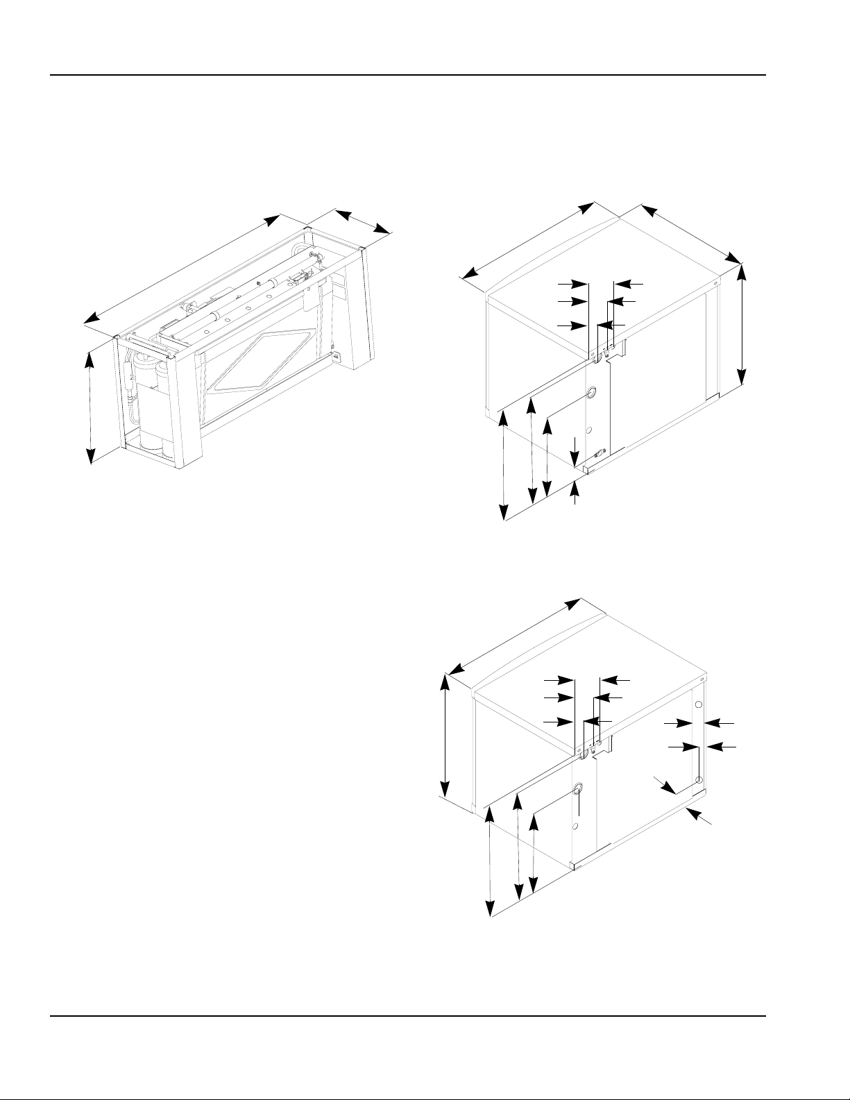
Installation Instructions
Ice Machine Dimensions
Q0600C/Q0800C/Q1000C ICE MACHINES
Ice Machine Dimension H
Q0600C 21.5 in (54.6 cm)
Q0800C 26.5 in (67.3 cm)
Q1000C 29.5 in (74.9 cm)
Section 2
Important
Failure to follow these installation guidelines may
affect warranty coverage.
IB0600C ICE MACHINE
30”
(76.2 CM)
(33 CM)
22”
(56 CM)
2.13”
(5.4 CM)
5.13”
(13.03 CM)
IB0800C ICE MACHINE
22”
(55.8 CM)
13”
8”
(20.3 CM)
4.5”
(11.4 CM)
5.5”
(14 CM)
24.5”
(62.23 CM)
H
SV1752
22”
(55.8 CM)
3”
(7.62 CM)
21”
(54.6 CM)
5.5”
(14 CM)
3”
(7.62 CM)
14”
(35.56 CM)
IB1000C ICE MACHINE
22”
(55.8 CM)
5.9”
(15 CM)
8.25”
(21 CM)
10”
(25.4 CM)
19.5”
(48.9 CM)
SV3093
26.5”
(67.31 CM)
3”
(7.62 CM)
5.5”
(14 CM)
3”
(7.62 CM)
14”
(35.56 CM)
5.9”
(15 CM)
8.25”
(21 CM)
12.7”
(32.26 CM)
21.8”
(55.4 CM)
SV3093
30.5”
(77.47 CM)
3”
(7.62 CM)
5.5”
(14 CM)
3”
(7.62 CM)
14”
(35.56 CM)
5.9”
(15 CM)
8.25”
(21 CM)
17.25”
(243.81 CM)
26”
(66 CM)
SV3093
Part No. 80-1206-3 2-1
Page 14
Installation Instructions Section 2
SU1000C ICE MACHINES
The SU1024YC is designed for installation on a SerVend
UC-300 dispenser only. Refer to the Servend UC-300
Installation Use and Care Manual for exterior
dimensions.
Q1400C ICE MACHINES
19”
(48.26 cm)
42”
(106.68 cm)
SV3003
12”
(30.48 cm)
30”
(76.2 cm)
6.87”
(17.45 cm)
3.24”
(8.23 cm)
14.77”
(37.52 cm)
20.96”
(53.24 cm)
21.21”
(53.87 cm)
QDUALC ICE MACHINE
2.02”
(5.13 cm)
5.37”
(13.64 cm)
24.5”
(62.23 cm)
(60.96 cm)
SV1766
24”
29.5”
(74.93 cm)
26.76”
(67.97 cm)
30”
(76.2 cm)
(17.45 cm)
3.24”
(8.23 cm)
26.54”
(67.4 cm)
6.87”
19.77”
(50.22 cm)
2”
(5.08 cm)
5.37”
(13.64 cm)
(5.31 cm)
(4.27 cm)
2.02”
(5.14 cm)
SV1766
2.09”
1.68”
2-2
Part No. 80-1206-3
Page 15

Section 2 Installation Instructions
Condensing Unit Dimensions
CVD0675/CVD0875/CVD1075/CVD1285/CVD1375/CVD1475
Air-Cooled
24.13”
(53.7 CM)
FRONT VIEW
25.75”
(65.4 CM)
14.5”
(36.8 CM)
34”
(86.4 CM)
14.5”
(36.8 CM)
9.5”
(24.1 CM)
CVD1476
Water-Cooled
21.87”
(55.5 CM)
12.6”
(32 CM)
4.26”
(10.8 CM)
8.54”
(21.6 CM)
24.53”
(62.3 CM)
20.64”
(52.4 CM)
CVD1875/CVD2075
Air-Cooled
26”
(66.04 CM)
10.25”
(26.04 CM)
13.5”
(34.3 CM)
10”
(25.4 CM)
(27.3 CM)
8”
(20.32 CM)
10.75”
5”
(12.7 CM)
52.5”
(133.35 CM)
6.5”
(16.5 CM)
(36.8 CM)
9”
10”
SV1758
(28.58 CM)
14.5”
11.5”
5.25”
(13.34 CM)
26”
(66.04 CM)
FRONT VIEW
8.70”
(22.1 CM)
PT1307
SV3076
Part No. 80-1206-3 2-3
Page 16

Installation Instructions Section 2
Location of Ice Machine
The location selected for the ice machine must meet the
following criteria. If any of these criteria are not met,
select another location.
• The location must be free of airborne and other
contaminants.
• The air temperature must be at least 35°F (1.6°C),
but must not exceed 110°F (43.4°C).
• The location must not be near heat-generating
equipment or in direct sunlight.
Ice Machine Head Section Clearance
Requirements
Q0600C/Q0800C/Q1000C/Q1400C/QDUALC:
Top/Sides 5” (127 mm) is recommended for efficient
operation and servicing. There is no minimum clearance
required.
Back 1” (25.4 mm) required when routing electrical inlet,
water inlet and refrigeration tubing out of the top of the
unit.
5” (127 mm) required when routing all connections out
the back.
IB0600C/IB0800C/IB1000C:
Top 2” (51 mm) required clearance for cleaning
procedures and servicing.
Back 5” (127 mm) required when routing all connections
out the back.
Sides 8” (203 mm) required for servicing.
SU1000C/SerVend UC-300:
Top 40” (101.6 cm) required clearance for cleaning
procedures and servicing.
Back 12” (30.5 cm) required for cleaning procedures
and servicing.
Caution
!
The ice machine head section must be protected if it
will be subjected to temperatures below 32°F (0°C).
Failure caused by exposure to freezing
temperatures is not covered by the warranty. See
“Removal from Service/Winterization”.
Stacking Two Ice Machines on a Single
Storage Bin
Q0600C/Q0800C/Q1000C Ice Machines:
A stacking kit is required for stacking two ice machines.
Installation instructions are supplied with the stacking kit.
IB0600C/IB0800C/IB1000C/Q1400C/QDUAL:
Ice Beverage, Q1400C and QDUAL ice machines
cannot be stacked. However an adapter is available that
allows two Q1400C or QDUALC ice machines to be
placed side by side on a 60” Manitowoc F style bin.
Securing the Ice Machine to the Dispenser
IB0600C/IB0800C/IB1000C Only
Important
Manitowoc Ice/Beverage Ice Machines require an
adapter for mounting. Adapters are not included
with the ice machine, dispenser or bin and must be
ordered separately. When a non-Manitowoc adapter
is used, verify the adapter is compatible with
Manitowoc Ice/Beverage Ice Machines prior to
installation.
Standard with IB ice machines and packaged in head
section is the dispenser thermostat kit, K-00209. It is
required that this kit be installed with all IB ice machines.
The thermostat kit must be installed before the adapter
and ice machine head section is installed.
The purpose of the thermostat kit is to reduce machine
overfill and condensation problems in high humidity
locations. It is recommended that bin level control be
used on all dispenser applications with timed agitation to
allow for better agitation in the bin.
The ice machine and adapter plate must be secured to
the dispenser to prevent tipping.
• Two holes are located in the front bottom rail of the
ice machine, to allow attachment to the adapter
plate.
• The adapter cover must be secured to the dispenser
to prevent ice from dislodging the cover during
agitation.
2-4
Warning
!
The ice machine and adapter plate must be secured
to the dispenser to prevent tipping.
Part No. 80-1206-3
Page 17

Section 2 Installation Instructions
TYPICAL ICE BEVERAGE ON A DISPENSER
Important
DO NOT REMOVE the label on bin adapters. The
retainer clips and brackets must be used.
1. Install bin level thermostat bracket.
2. Set adapter on dispenser. Position the adapter so
that the front flange of the adapter will be up against
the front lip of the dispenser. Adapter may have to
be moved towards the back of the dispenser.
3. Using the slotted holes in the adapter as a template,
drill four (4) 9/64” diameter holes at the bottom of the
slots. Note: Do not drill deeper than 1/4” past the
sheet metal. Use a drill stop!
4. Fasten the adaptor to dispenser using the four (4) #8
screws supplied with the adaptor kit.
5. Set the ice machine on top of the adapter. Align
holes in ice machine front angle with threaded
bosses on the adapter.
BIN
COVER
ADAPTER
6. Secure the ice machine to the adaptor with two (2)
#8-32 screws supplied with the kit.
7. Set the bin cover on the adapter, move backwards
until the cover hits the stop, and lower the plastic
cover insuring that the latch locks.
8. To remove the bin cover, twist the knob, lift up, and
pull forward.
PLACE A LARGE FILLET OF
FOOD GRADE RTV INSIDE
EDGE ALONG BOTH SIDES
WHERE ADAPTER
TOUCHES BIN
SV3121
SCREWS
SV3122
DEFLECTOR MUST
STAY IN PLACE
SV3120
Part No. 80-1206-3 2-5
Page 18

Installation Instructions Section 2
Location of CVD Condensing Unit
The location selected for the CVD Condensing Unit must
meet the following criteria. If any of these criteria are not
met, select another location.
• The air temperature must be at least -20°F (-28.9°C)
but must not exceed 130°F (54.4°C).
• CVD1476 Only - The air temperature must be at
least 50°F (10°C) but must not exceed 110°F (43°C).
• CVD1875/CVD2075 Only - The air temperature must
be at least -20°F (-28.9°C) but must not exceed
120°F (48.9°C).
• The location must not allow exhaust fan heat and/or
grease to enter the condenser.
• The location must not obstruct airflow through or
around the condensing unit. Refer to the chart below
for clearance requirements.
Condensing Unit Clearance Requirements
Top/Sides
There is no minimum clearance required, although 6”
(152 mm) is recommended for efficient operation and
servicing only.,
Front/Back
48” (122 cm)
CVD1476 ONLY
Top - 5” (127 mm) is recommended for efficient
operation and servicing only.
Front/Back/Sides - 12” (305 mm)
Condensing Unit Heat of Rejection
Series
Condensing Unit
CVD675 9,000 13,900
CVD875 12,400 19,500
CVD1075 16,000 24,700
CVD1285 19,000 28,000
CVD1475 24,000 35,500
CVD1476 24,000 35,500
CVD1875 28,000 42,000
CVD2075 39,000 53,000
B.T.U./Hour
Because the heat of rejection varies during the ice making cycle,
the figure shown is an average.
Air Conditioning**
Heat of Rejection*
QuietQube® ice machine head sections add an
insignificant amount of load to a conditioned space.
Peak
2-6
Part No. 80-1206-3
Page 19

Section 2 Installation Instructions
Leveling the Ice Storage Bin
1. Screw the leveling legs onto the bottom of the bin.
2. Screw the foot of each leg in as far as possible.
Caution
!
The legs must be screwed in tightly to prevent them
from bending.
3. Move the bin into its final position.
4. Level the bin to assure that the bin door closes and
seals properly. Use a level on top of the bin. Turn
each foot as necessary to level the bin.
NOTE: An optional caster assembly is available for use
in place of the legs. Installation instructions are supplied
with the casters.
Air-Cooled Baffle
The air-cooled baffle prevents condenser air from
recirculating. To install:
1. Remove the back panel screws next to the
condenser.
2. Align the mounting holes in the air baffle with the
screw holes and reinstall the screws.
SCREWS
AIR
BAFFLE
THREAD ‘FOOT’ IN AS
FAR AS POSSIBLE
Leveling Leg and Foot
THREAD LEVELING
LEG INTO BASE OF
CABINET
SV1606
SV1607
Air Baffle
Part No. 80-1206-3 2-7
Page 20

Installation Instructions Section 2
Electrical Service
GENERAL
Warning
!
All wiring must conform to local, state and national
codes.
VOLTAG E
The maximum allowable voltage variation is ±10% of the
rated voltage at ice machine start-up (when the electrical
load is highest).
Warning
!
The ice machine must be grounded in accordance
with national and local electrical codes.
FUSE/CIRCUIT BREAKER
A separate fuse/circuit breaker must be provided for
each ice machine. Circuit breakers must be H.A.C.R.
rated (does not apply in Canada).
MINIMUM CIRCUIT AMPACITY
The minimum circuit ampacity is used to help select the
wire size of the electrical supply. (Minimum circuit
ampacity is not the ice machine’s running amp load.)
The wire size (or gauge) is also dependent upon
location, materials used, length of run, etc., so it must be
determined by a qualified electrician.
2-8
Part No. 80-1206-3
Page 21

Section 2 Installation Instructions
Electrical Requirements
QuietQube® Ice Machine Head Section
Vol tag e
Ice Machine
Q0600C IB0600C
Q0800C IB0800C
Q1000C IB1000C
SU1000C (UC-300 Dispenser)
Q1400C QDUALC
CVD® Condensing Unit
Condensing Unit
CVD0675
CVD0875
CVD1075
CVD1285
CVD1475
CVD1476
CVD1875
CVD2075
Phase
Cycle
115/1/60
208-230/1/60
230/1/50
Important
The QuietQube® Ice Machine Head Section and
CVD Condensing Unit are wired independently from
each other.
Voltage Phase
Cycle
208-230/1/60
208-230/3/60
230/1/50
208-230/1/60 20 11. 7
208-230/3/60
230/1/50
208-230/1/60 25 15.6
208-230/3/60
230/1/50
208-230/1/60 25 14.7
208-230/3/60
230/1/50
208-230/1/60
208-230/3/60
230/1/50
208-230/1/60 30 15.3
208-230/3/60 20 10.8
208-230/1/60 40 24.3
208-230/3/60 30 16.1
230/1/50 40 23.2
208-230/1/60 50 27.1
208-230/3/60 40 19.9
230/1/50 50 29.9
Maximum Fuse/
Circuit Breaker
15 amp
15 amp
15 amp
Maximum Fuse/Circuit
Breaker
15 9.6
15 7.3
15 9.0
15 8.2
20 11. 3
20 10.6
25 13.8
20 10.6
25 11. 7
35 19.6
25 14.1
35 19.8
Total Amps
1.1
0.6
0.6
Minimum Circuit Amps
Part No. 80-1206-3 2-9
Page 22

Installation Instructions Section 2
QuietQube® Ice Machine Head Section Electrical Wiring Connections
!
Warning
These diagrams are not intended to show proper
wire routing, wire sizing, disconnects, etc., only the
correct wire connections.
All electrical work, including wire routing and
grounding, must conform to local, state and national
electrical codes.
Though wire nuts are shown in the drawings, the ice
machine field wiring connections may use either
wire nuts or screw terminals.
QUIETQUBE® ICE MACHINE HEAD SECTION
115/1/60 OR 208-230/1/60
L
1
N=115V
OR
L2=208-230V
GROUND
GROUND
QUIETQUBE® ICE MACHINE HEAD SECTION
230/1/50
L
1
N
GROUND
GROUND
L
1
ICE MACHINE
CONNECTIONS
TO SEPARATE
FUSE/BREAKER.
DISCONNECT ALL
POLES.
L
1
N
SV1191
ICE MACHINE
CONNECTIONS
SV1258
For United Kingdom Only
As the colours of the wires in the mains lead of the appliance may not correspond with the coloured markings
identifying the terminals in your plug, proceed as follows:
• The wire which is coloured green and yellow
the letter E or by the earth ground symbol or coloured green or green and yellow.
• The wire coloured blue
• The wire coloured brown
must be connected to the terminal which is marked with the letter N or coloured black.
must be connected to the terminal which is marked with the letter L or coloured red.
must be connected to the terminal in the plug which is marked with
2-10
Part No. 80-1206-3
Page 23

Section 2 Installation Instructions
Remote Electrical Wiring Connections
!
Warning
These diagrams are not intended to show proper
wire routing, wire sizing, disconnects, etc., only the
correct wire connections.
All electrical work, including wire routing and
grounding, must conform to local, state and national
electrical codes.
Though wire nuts are shown in the drawings, the ice
machine field wiring connections may use either
wire nuts or screw terminals.
CVD CONDENSING UNIT
208-230/1/60
L
1
L
L2
CVD CONDENSING UNIT
208-230/3/60
L
L
L
GROUND
SV1190
1
2
3
L
1
L
2
L
3
GROUND
CONDENSING
UNIT
CONNECTIONS
1
CVD CONDENSING UNIT
TO SEPARATE
FUSE/BREAKER
230/1/50
L
1
L
1
GROUND
CONDENSING UNIT
CONNECTIONS
GROUND
TO SEPARATE
FUSE/BREAKER
SV1258
N
GROUND
CONDENSING UNIT
CONNECTIONS
N
GROUND
TO SEPARATE
FUSE/BREAKER.
DISCONNECT ALL
POLES.
SV1191
Part No. 80-1206-3 2-11
Page 24

Installation Instructions Section 2
Ice Machine Head Section Water Supply
and Drains
POTABLE WATER SUPPLY
Local water conditions may require treatment of the
water to inhibit scale formation, filter sediment, and
remove chlorine odor and taste.
Important
If you are installing a Manitowoc water filter system,
refer to the Installation Instructions supplied with the
filter system for ice making water inlet connections.
POTABLE WATER INLET LINES
Follow these guidelines to install water inlet lines:
• Do not connect the ice machine to a hot water
supply. Be sure all hot water restrictors installed for
other equipment are working. (Check valves on sink
faucets, dishwashers, etc.)
• If water pressure exceeds the maximum
recommended pressure, obtain a water pressure
regulator from your Manitowoc distributor.
Float Valve - 80 psig (551.5 kPA)
Water Inlet Valve - 90 psig (620.4 kPA)
• Install a water shut-off valve for ice making potable
water.
• Insulate water inlet lines to prevent condensation.
DRAIN CONNECTIONS
Follow these guidelines when installing drain lines to
prevent drain water from flowing back into the ice
machine and storage bin:
• Drain lines must have a 1.5 inch drop per 5 feet of
run (2.5 cm per meter), and must not create traps.
• The floor drain must be large enough to
accommodate drainage from all drains.
• Run separate bin and ice machine drain lines.
Insulate them to prevent condensation.
• Vent the bin and ice machine drain to the
atmosphere. The ice machine drain requires an 18”
vent.
• Drains must have a union or other suitable means to
allow in place disconnection from the ice machine
when servicing is required.
• The SU1024YC is designed for installation on a
SerVend UC300 dispenser only. Refer to the
SerVend UC300 Installation, Use and Care Manual
for additional drain requirements.
• A 3’ service loop or disconnect (union) must be
installed at the ice machine head section on Ice
Beverage models.
2-12
Part No. 80-1206-3
Page 25

Section 2 Installation Instructions
Water Cooled Condenser Water Supply and
Drains
CONDENSER WATER SUPPLY
Local water conditions may require treatment of the
water to inhibit scale formation, filter sediment, and
remove chlorine odor and taste.
WATER COOLED CONDENSER LINES
Follow these guidelines to install water lines:
• Contact your distributor if your water pressure is
greater than 150 psig (1034 kPA). A special order
condensing unit is available that allows water
pressure up to 350 psig (2413 kPA).
• Install a shutoff valve (inlet and outlet on cooling
tower or closed loop circuits) to allow isolation of the
water system.
• Water entering the condenser must not exceed 90°F
(32.2°C).
• Water flow through the condenser must not exceed 5
gallons (19 liters) per minute.
• Allow for a pressure drop of 8 psig (55 kPA) between
the condenser water inlet and outlet.
• Water exiting the condenser must no exceed 110°F
(43.3°C).
CONDENSING UNIT DRAIN CONNECTIONS
The condensing unit drain is provided to remove any
condensate produced by the suction accumulator.
Condensate amounts will vary depending on
temperature and humidity.
• The condensing unit must be level front to back and
side to side to allow the condensate to drain.
• Drain lines must have a 1.5-inch drop per 5 feet of
run (2.5 cm per meter), and must not create traps.
• Drain termination must meet applicable costs.
!
Warning
Water pressure at the condenser cannot exceed
150 psig (1034 kPA) with the standard water
regulating valve. Contact your distributor if your
water pressure is greater than 150 psig (1034 kPA).
A special order condensing unit is available that
allows water pressure up to 350 psig (2413 kPA).
Part No. 80-1206-3 2-13
Page 26

Installation Instructions Section 2
Refrigeration System Installation
QuietQube®
Ice Machine
Q1000C
IB1000C
SU1000C/UC300
Q1400C
Q0600C
IB0600C
Q0800C
IB0800C
QDUALC
Line Set Suction Line Liquid Line
RC 20/30/50 3/4 inch
RC 21/31/51
RC 22/32/52
USAGE WITH NON-MANITOWOC
CONDENSING UNITS
Manitowoc CVD Condensing Units are specifically
designed for usage with a QuietQube® Ice Machine
Head Section. Non-Manitowoc condensing units will not
operate a QuietQube® Ice Machine Head Section.
SU1000C/Servend UC-300 Dispenser
Refrigeration system installation must meet the
requirements and follow the procedures listed in this
section.
Installation of a QuietQube® Condensing Unit may
require the use of special equipment for placement.
Trained and qualified personnel are required for
proper rigging and lifting.
Remote Single
Condenser
CVD1075
CVD1285
CVD1475
CVD1476
CVD675
CVD875
CVD875
CVD1875
CVD2075
(19.1 mm)
5/8 inch
(15.9 mm)
7/8 inch
(22.2 mm)
!
Circuit
(12.7 mm)
(9.5 mm)
(15.9 mm)
Warning
1/2 inch
3/8 inch
5/8 inch
Line Set*
RC-20
RC-30
RC-50
RC-21
RC-31
RC-51
RC-22
RC-32
RC-52
Insulation
Thickness
1/2”(13mm)
Suction Line
1/4” (7mm)
Liquid Line
3/4” (19mm)
Suction Line
1/4” (7mm)
Liquid Line
Factory Equipment Refrigeration Amounts
ICE MACHINE HEAD SECTION
Q0600C/IB0600C/Q0800C/IB0800C/Q1000C/IB1000C/
SU1000C/Q1400C
Each ice machine head section ships from the factory
with a R-404A refrigerant charge appropriate for the
entire system operation. The serial tag on the ice
machine indicates the refrigerant charge. The refrigerant
charge is sufficient to operate the ice machine in
ambient temperatures between -20°F (-28.9°C) and
130°F (54.4°C)*. With line set lengths of up to 100 feet
(30.5 m).
*CVD1476: -50°F to 110°F (-46°C to 43°C)
QDUALC
Each QDUALC ice machine head section ships from the
factory with an R-404A refrigerant charge appropriate for
installations with up to 50’ of refrigeration tubing. The
serial tag on the ice machine indicates the refrigerant
charge. For line set runs longer than 50’ 1 lb. of
additional refrigerant must be added for each 10’ of line
set run. The receiver is designed to hold a charge
sufficient to operate the ice machine in ambient
temperatures between -20°F (-28.9°C) and 120°F
(49°C), with line set lengths of up to 100 feet (30.5 m).
!
Warning
The ice machine head section contains the refrigerant
charge. Installation and brazing of the line sets must
be performed by a properly trained and EPA certified
refrigeration technician aware of the dangers of
dealing with refrigerant charged equipment.
Caution
!
Never add more than nameplate charge to the
refrigeration system for any application.
Caution
!
The 60-month compressor warranty (including the
36-month labor replacement warranty) will not apply if
the Manitowoc Ice Machine and Manitowoc CVD
Condensing Unit are not installed according to
specifications. This warranty also will not apply if the
refrigeration system is modified with a condenser,
heat reclaim device, or other parts or assemblies not
manufactured by Manitowoc Ice, Inc.
2-14
Part No. 80-1206-3
Page 27

Section 2 Installation Instructions
Refrigeration Line Set Installation
GENERAL
Refrigeration line set installations consist of vertical and
horizontal line set distances between the ice machine
and the condensing unit. The following guidelines,
drawings and calculation methods must be followed to
assure proper oil return and CVD condensing unit/ice
machine operation
!
Warning
The following instructions are provided as a general
overview of a typical QuietQube® installation. Refer
to the Installation, Use and Care Manual for each
specific model for step by step installation
instructions.
Step 1 Verify Ice Machine and CVD Condensing
Unit Locations Are Within Guidelines.
Prior to installation of the ice machine head section and
CVD condensing unit be sure that the distance between
then is within the line set routing guidelines outlined in
this manual.
Roof/Wall Penetration
If required, cut a 3-inch (76.2 mm) circular hole in the
wall or roof for routing of refrigeration tubing. A qualified
person must perform all roof penetrations.
Step 2 Route Refrigeration Tubing
Properly route refrigeration tubing between the ice
machine head section and the CVD condensing unit.
B. LINE SET RISE OR DROP
35’ (10.7 M)
MAX.
DISTANCE
SV1751
35 feet (10.7 m) Rise: The maximum distance the CVD
condensing unit can be above the ice machine.
15’ (4.5 M)
MAX.
DISTANCE
SV1750
A. LINE SET LENGTH
100 feet (30.5 m) Length: The maximum measured
length the line set can be.
Important
QuietQube® ice machines will not function with line
sets greater than 100 feet (30.5 m). Do not attempt to
go beyond this distance and add refrigerant charge to
compensate!
15 feet (4.5 m) Drop: The maximum distance the CVD
condensing unit can be below the ice machine.
Part No. 80-1206-3 2-15
Page 28

Installation Instructions Section 2
C. SUCTION LINE OIL TRAPS
Caution
!
Do not form unwanted traps in refrigeration lines.
Never coil excess refrigeration tubing.
0 to 20 feet (0 to 6.1 m) Rise: The ice machine head
section has one oil trap built in which allows for a
maximum condenser rise of 20 feet (6.1 m) without
additional traps in the suction line.
21 to 35 feet (6.4 to 10.7 m) Rise: The suction line
requires an additional Oil Trap (“S” type) to be installed.
Install the trap as close as possible to midpoint between
the ice machine head section and CVD condensing unit.
S-Trap Kits are available from Manitowoc (refer to chart).
21’ OR MORE
RISE
ADDITIONAL
TRAP KIT
REQUIRED
Service Loop
A service loop in the line set permits easy access to the
ice machine for cleaning and service.
A service loop is an installation requirement on Ice
Beverage Ice Machines. (IB0600C/IB0800C/IB1000C)
SERVICE LOOP
SV3088
• The supplied service loop is an installation
requirement. Excess tubing length must be
sufficient to allow 180° rotation of the ice
machine.
• A service loop is not considered an oil trap.
• The service loop is not included when calculating
length, rise or drop of the tubing run.
• Do not use hard rigid copper for the service loop.
Manitowoc S-Trap Kit
Model S-Trap Kit
Q0600C
IB0600C
Q0800C
IB0800C
Q1000C
IB1000C
SU1000C
Q1400C
QDUALC K000164
Number
K00172
K00166
Tubing Size
5/8 inch
(15.9 mm)
3/4 inch
(19.1 mm)
7/8 inch
(22.2 mm)
SV1751
SV1760
Caution
!
If a line set has a rise followed by a drop, another rise
cannot be made. Likewise, if a line set has a drop
followed by a rise, another drop cannot be made.
Step 3 Lengthening or Reducing Line Set Lengths
Caution
!
Do not form unwanted traps in refrigeration lines.
Never coil excess refrigeration tubing.
When the line set required shortening or lengthening, do
so before connecting the line set to the ice machine
head section or the CVD condensing unit.
2-16
Part No. 80-1206-3
Page 29

Section 2 Installation Instructions
Step 4 Connecting the line set.
To prevent oxidation of the copper, purge line set and
condensing unit with dry nitrogen while brazing.
Connect The Line Set To The Ice Machine Head
Section
!
Warning
The ice machine head section contains refrigerant
charge. The ice machine head section contains three
(3) refrigeration valves that must remain closed until
proper installation of the line sets is completed.
The line set shut off valves at the back of the ice
machine must remain closed and be protected from heat
during the brazing process. Wrap the valves in a wet rag
or other type of heat sink prior to brazing. Cool braze
joint with water immediately after brazing to prevent heat
migration to the valve.
Connect The Line Set To The CVD Condensing Unit
The compressor oil rapidly absorbs moisture. Be
prepared to complete line set installation and start your
evacuation process in order to minimize the time the
compressor is exposed to the atmosphere. (Maximum
amount of time the system can be exposed to the
atmosphere is 15 minutes). The line set can be routed
for entry through the front or left side of the condensing
unit.
• Remove knockout for preferred location.
• Insert supplied plastic bushings in knockout holes to
prevent tubing from contacting sheet metal.
• Use the supplied 90° elbows to route tubing.
• Cut the tubing ends of the suction and liquid lines
and braze the line sets to the condensing unit.
SUCTION
FILTER
VALVES MUST REMAIN
CLOSED AND BE
PROTECTED FROM
HEAT WHEN BRAZING
(WRAP WITH WET RAG)
Q600C/Q800C/Q1000C
Warning
!
SHOWN
SV1757
The condensing unit ships from the factory
pressurized with a 50/50 mixture of nitrogen/helium.
Bleed off pressure from both suction and liquid line
access ports prior to cutting into refrigeration lines.
SUCTION
LINE
MINIMIZE THE TIME THE REFRIGERATION
SYSTEM IS EXPOSED TO THE ATMOSPHERE
LIQUID
LINE
SUCTION
LINE
(15 MINUTES MAXIMUM)
CVD1476
SV2085
SV3077
Part No. 80-1206-3 2-17
Page 30

Installation Instructions Section 2
Step 5 Pressure Test and Evacuate The Line Set
and CVD Condensing Unit
Schrader valve core removal tools that allow for removal
and installation of the valve cores without removing
manifold gauge set hoses are recommended to
decrease the evacuation time.
Leave the line set shut off valves closed (front seated).
Pressure test the line sets and CVD condensing unit
with 150 psig of dry nitrogen. Add nitrogen at the line set
shut off valves located at the back of the ice machine.
Complete the pressure test, verify no leaks are present
and remove the nitrogen from the system before
connecting the vacuum pump. Connect a vacuum pump
to both of the line set shut off valves located at the back
of the ice machine head section. Evacuate to 250
microns (or less). To completely evacuate the CVD
condensing unit, continue the evacuation for 30 minutes
after reaching the 500 micron point.
ALTERNATE CONNECTIONS AT
CONDENSING UNIT SCHRADER VALVES
Step 6 Open The Valves Prior To Starting The Ice
Machine.
A. Slowly backseat (open-turn counterclockwise)
the suction line shut off valve.
B. Slowly backseat (open-turn counterclockwise)
the liquid line shut off valve.
C. Slowly backseat (open-turn counterclockwise)
the receiver service valve.
NOTE: You will not hear refrigerant flow when the valves
are opened. Refrigerant will not flow until the toggle
switch is placed in the ice position and the liquid line
solenoid valve opens.
USE ALLEN WRENCH TO OPEN
(TURN COUNTERCLOCKWISE)
LIQUID AND SUCTION LINE
SHUT OFF VALVES
OPEN SUCTION AND LIQUID LINE SHUT OFF VALVES
Q0600C/Q0800C/Q1000C
SV1762
SV2085
If required, the line set and condensing unit can be
evacuated from the schrader valves located in the CVD
condensing unit. Schrader valve core removal tools (that
allow for putting the cores back in without removing
vacuum pump hoses) must be used if evacuating from
the condensing unit side.
Isolate the vacuum pump from the line set shut off
valves and/or condensing unit access ports prior to
proceeding. Open refrigeration system shut off valves.
The suction line, liquid line and receiver service valves
are closed during shipment and installation.
CONNECT
VACUUM PUMP TO
LINE SET SHUT
OFF VALVES
SV1757
USE ALLEN WRENCH TO OPEN
(TURN COUNTERCLOCKWISE)
LIQUID AND SUCTION LINE SHUT
OFF VALVES
SV1769C
OPEN SUCTION AND LIQUID LINE SHUT OFF VALVES
Q1400C/QDUALC
USE ALLEN WRENCH
TO OPEN (TURN
COUNTERCLOCKWISE)
LIQUID AND SUCTION
LINE SHUT OFF
VALV ES
SV3051
OPEN SUCTION AND LIQUID LINE SHUT OFF VALVES
IB0600C/IB0800C/IB1000C
2-18
Part No. 80-1206-3
Page 31

Section 2 Installation Instructions
Verify O-ring in schrader valve caps are intact and
reinstall on shut off valves to prevent refrigerant leakage.
Replace shut off valve access caps and torque to the
following specifications.
Torque Value’s
Stem 18-20 ft. lbs.
Caps 12-15 ft. lbs.
Schrader Core 1.5-3 in. lbs.
Replace cap on receiver service valve and tighten.
TURN
COUNTERCLOCKWISE
RECEIVER SERVICE VALVE CAP
(TURN COUNTERCLOCKWISE
TO REMOVE)
SV1756
Open Receiver Service Valve
There is a liquid line solenoid valve at the outlet of the
receiver; refrigerant will not flow to the condensing unit
until the ice machine head section is started. Connect
power to both the ice machine head section and the
CVD condensing unit. Place the ICE/OFF/CLEAN toggle
switch into the ICE position, this will allow refrigerant to
enter the line set and condensing unit.
Important
All refrigeration valve caps must be reinstalled to
prevent future refrigeration leaks.
Step 7 Leak Check The Refrigeration System
Leak check the new line set connections at the ice
machine head section, condensing unit and S trap as
well as all factory joints throughout the entire system.
Disconnect power to the CVD condensing unit. Place the
ICE/OFF/CLEAN toggle switch into the ICE position.
This allows the low side and high side pressures to
equalize. Place the ICE/OFF/CLEAN toggle switch in the
OFF position. Connect power to the CVD condensing
unit and allow system to pump down.
Step 8 Insulation Requirements
To prevent condensation the entire suction line including
the shut-off valve must be insulated. All insulation must
be airtight and sealed at both ends.
The following insulation requirements prevent
condensation at 90°F (32.2°C) ambient 90% Relative
Humidity. If higher humidity is expected, increase
insulation thickness.
The entire suction line set, including the suction service
valve located on the back of the ice machine requires:
Suction Line Liquid Line Min. Insulation
Thickness
3/4 inch
(19.1 mm)
5/8 inch
(15.9 mm)
7/8 inch
(22.2 mm)
1/2 inch
(12.7 mm)
3/8 inch
(9.5 mm)
5/8 inch
(15.9 mm)
1/2”(13mm)
Suction Line
1/4” (7mm)
Liquid Line
3/4” (19mm)
Suction Line
1/4” (7mm)
Liquid Line
Important
To prevent condensation the entire suction line
including the shut off valve must be insulated. All
insulation must be airtight and sealed at both ends.
The minimum requirements are for conditions at or
below 90% humidity and 90°F (32.2°C) ambient.
When higher humidity will be experienced, insulation
wall thickness will need to be increased.
Part No. 80-1206-3 2-19
Page 32

Installation Instructions Section 2
Suction Shut Off Valve Insulation
The pre-formed suction shut-off valve insulation is
located in the plastic bag taped to the water curtain.
A. Verify valve and schrader caps are tightened to
specifications (see Step 6).
PRE-FORMED
INSULATION
TIGHTEN VALVE CAPS
TO SPECIFICATIONS
SV3084
B. Place insulation over schrader valve cap and left
side of valve. Position the tab between the
mounting bracket and rear panel.
PLACE TAB BETWEEN
VALVE BODY AND PANEL
3 Phase Scroll Compressor Rotation
CVD2075 Only
A trained and qualified technician must verify
compressor rotation at equipment startup or compressor
warranty will be void. Incorrect rotation of a scroll
compressor can be identified by:
• Noisy compressor operation
• Elevated suction pressure
• Low discharge pressure
• Compressor trips on overload protector
To change compressor rotation, reverse (exchange
locations) any two incoming power supply leads.
Test run ice machine in the freeze and harvest cycles,
then place toggle switch in OFF position and verify
condensing unit cycles off.
SV3085
C. Fold insulation and hold against right hand side
of valve while securing with electrical tape. Seal
the line set insulation to the shut off valve
insulation with electrical tape.
FOLD INSULATION OVER
RIGHT SIDE OF VALVE AND
SECURE WITH
ELECTRICAL TAPE
SV3086
2-20
Part No. 80-1206-3
Page 33

Section 2 Installation Instructions
Electronic Bin Thermostat Instructions
POSITIONING
1. Remove screws.
2. Remove backing on 2 sided tape.
3. Rotate and position vertically. Re-install both
screws.
FINAL
POSITION
SHIPS
HORIZONTAL
TO PROTECT
PROBE
Bin Thermostat Location
Control Location
CONTROL
LOCATION
Part No. 80-1206-3 2-21
Page 34

Installation Instructions Section 2
THIS PAGE INTENTIONALLY LEFT BLANK
2-22
Part No. 80-1206-3
Page 35

Component Identification
5
ICE MACHINE HEAD SECTION
Q0600C/Q0800C/Q1000C
Section 3
Maintenance
COOL
VAPOR
VALVE
WATER
INLET
VALVE
WATER DUMP
VALVE
DRAIN
HOSE
LIQUID LINE
SHUT-OFF VALVE
ICE MACHINE HEAD SECTION
IB0600C/IB0800C/IB1000C
ELECTRICAL
COMPARTMENT
OFF/ICE/CLEAN
TOGGLE
SWITCH
iCE
THICKNESS
PROBE
LIQUID
LINE SOLENOID
VALVE
RECEIVER
SERVICE
VALVE
RECEIVER
SUCTION LINE
SHUT-OFF VALVE
WATER
DISTRIBUTION TUBE
SV1754
SHUT OFF
VALVES
DISTRIBUTION
TUBE
WATER CURTAIN
DISCHARGE
LINE
CHECK
VALVE
ICE THICKNESS
PROBE
WATER TROUGH
EVAPORATOR
WATER PUMP
ELECTRICAL
COMPARTMENT
FLOW CLAMP USED
ON REGULAR SIZE
CUBE ONLY
ICE/OFF.CLEAN
SWITCH
SV160
RECEIVER
SERVICE
VALVE
WATER
INLET
VALVE
LIQUID
LINE
DRYER
WATER
CURTAIN
WATER
TROUGH
DUMP
VALVE
SV3087
RECEIVERS
LIQUID LINE
SOLENOID
VALVE
COOL
VAPOR
VALVE
SV3051a
Part No. 80-1206-3 3-1
Page 36

Maintenance Section 3
ICE MACHINE HEAD SECTION
SU1000C - SERVEND UC-300 DISPENSER
WATER
DISTRIBUTION
TUBE
SERVICE VALVE
WATER
CURTAIN
RECEIVER
SHUT-OFF VALVES
ICE
THICKNESS
PROBE
WATER
TROUGH
OFF/ICE/CLEAN
TOGGLE
SWITCH
ELECTRICAL
COMPARTMENT
DUMP
VALVE
WATER
PUMP
WATER FLOAT
VALVE
COOL VAPOR
SOLENOID
VALVE
LIQUID LINE
SOLENOID
VALVE
ICE MACHINE HEAD SECTION
Q1400C/QDUALC
EVAPORATOR
WATER
PUMP
DISTRIBUTION
TUBE
SV2080
WATER PUMP /
FLOA T VALVE
ACCESS PANELS
SUCTION LINE
SHUT-OFF
VALVE
LIQUID LINE
SHUT-OFF
VALVE
COOL
VAPOR
VALVE
SV2081
3-2
WATER
CURTAIN
WATER
TROUGH
SV1780
RECEIVER
SERVICE
VALVE
RECEIVER
LIQUID LINE
SOLENOID
VALVE
WATER
DUMP VALVE
SV1770RH
Part No. 80-1206-3
Page 37

Section 3 Maintenance
E
A
ICE MACHINE HEAD SECTION
Q1400C/QDUALC
COOL VAPOR
VALVE
ICE
THICKNESS
PROBE
ICE/OFF/CLEAN
FLOAT VALVE
(WATER INLET)
TOGGLE
WITCH
SV1770LH
CVD CONDENSING UNIT
CVD0675/CVD0875/CVD1075/CVD1285/CVD1475
ACCESS
VALVES
ELECTRICAL
COMPARTMENT
LIQUID LINE AND
SUCTION LINE
CONNECTION
POINTS
ACCUMULATOR
SUCTION
CONDENSER
FAN MOTOR
COMPRESSOR
AIR
CONDENSER
PRESSUR
CONTROL
HEAD
VALVE
SV2085
CVD CONDENSING UNIT
CVD1476
LIQUID LINE
AND
SUCTION LINE
CONNECTION
POINTS
WATER
REGULATING
VALVE
SUCTION
ACCUMULATOR
HEAD PRESSURE
CONTROL VALVE
COMPRESSOR
ELECTRICAL
COMPARTMENT
WATER
COOLED
CONDENSER
CVD CONDENSING UNIT
CVD1875/CVD2075
ACCESS
VALVES
ELECTRICAL
COMPARTMENT
LIQUID LINE
AND
SUCTION LINE
CONNECTION
POINTS
CONDENSER
FAN MOTOR
SUCTION
ACCUMULATOR
AIR
CONDENSER
HEAD PRESSURE
CONTROL VALVE
COMPRESSOR
PT1306
CVD1875 Shown - CVD2075 has same layout with
PT1382
Part No. 80-1206-3 3-3
two condenser fan motors
Page 38

Maintenance Section 3
Operational Checks
GENERAL
Manitowoc ice machines are factory-operated and
adjusted before shipment. Normally , a newly inst alled ice
machine does not require any adjustment.
To ensure proper operation, always follow the
Operational Checks:
• when starting the ice machine for the first time
• after a prolonged out of service period
• after cleaning and sanitizing
NOTE: Routine adjustments and maintenanc e
procedures outlined in this manual are not covered by
the warranty.
Important
CVD2075 Condensing Units
A scroll compressor must be operated for a
minimum break in period of 72 hours before full ice
production capacity will be reached.
WATER LEVEL
Q0600C/Q0800C/Q1000C/QDUALC
The water level sensor is set to maintain the proper
water level above the water pump housing. The water
level is not adjustable.
If the water level is incorrect, check the water level probe
for damage (probe bent, etc.). Repair or replace the
probe as necessary.
WATER LEVEL
Q1400C/SU1000C
1. Check the water level while the ice machine is in the
freeze mode and the water pump is running. The
correct water level is:
• Q1400C - 1/8” - 1/2” (3-12.5 mm)
• SU1000C - 1/8” - 1/4” (3-6.35 mm)
2. The float valve is factory set for the proper water
level. If adjustments are necessary:
A. SU1000C Only-Remove the thumbscrews and
access panels from the float valve/water pump
chimney (located behind the evaporator).
B. Loosen the two screws on the float valve
bracket.
C. Raise or lower the float valve assembly as
necessary then tighten the screws.
D. If further adjustment is required, carefully bend
the float arm to achieve the correct water level.
WATER PUMP
IMPELLER
HOUSING
SV1616
3-4
Water Level Probe
SV1616A
Q1400C Shown
WATER LEVEL
IB0600C/IB0800C/IB1000C
The water level sensor is set to maintain the proper
water level above the water pump housing. The water
level is not adjustable. Correct water level is
approximately 2.5” (63.5 mm). If the water level is
incorrect, check the water level probe for damage (probe
bent, etc.). Repair or replace the probe as necessary.
WATER
LEVEL
PROBE
WATER
LEVEL
SV3090
Part No. 80-1206-3
Page 39

Section 3 Maintenance
ICE THICKNESS CHECK
After a harvest cycle, inspect the ice cubes in the ice
storage bin. The ice thickness probe is factory-set to
maintain the ice bridge thickness at 1/8" (3.2 mm).
NOTE: Make sure the water curtain is in place when
performing this check. It prevents water from splashing
out of the water trough.
1. Inspect the bridge connecting the cubes. It should
be about 1/8" (3.2 mm) thick.
2. If adjustment is necessary, turn the ice thickness
probe adjustment screw clockwise to increase
bridge thickness, counterclockwise to decrease
bridge thickness.
NOTE: Turning the adjustment 1/3 of a turn will change
the ice thickness about 1/16" (1.5 mm).
ADJUSTING SCREW
HARVEST SEQUENCE WATER PURGE
Q0600C/IB0600C/Q0800C/IB0800C/
Q1000C/IB1000C/QDUAL
The harvest sequence water purge adjustment may only
be used when the ice machine is hooked up to special
water systems, such as a de-ionized water treatment
system.
Important
The harvest sequence water purge is factory-set at
45 seconds. A shorter purge setting (with standard
water supplies such as city water) is not
recommended. This can increase water system
cleaning and sanitizing requirements.
• The harvest sequence water purge may be set to 15,
30, or 45 seconds.
• During the harvest sequence water purge, the water
fill valve energizes and de-energizes by time. The
water purge must be at the factory setting of 45
seconds for the water fill valve to energize during the
last 15 seconds of the water purge. If it is set to less
than 45 seconds, the water fill valve will not energize
during the water purge.
1/8” ICE BRIDGE THICKNESS
SV3114
Ice Thickness Check
3. Make sure the ice thickness probe wire and the
bracket do not restrict movement of the probe.
CONTROL
BOARD
WATER PURGE
ADJUSTMENT
30
15
45
SV1617
Water Purge Adjustment
Part No. 80-1206-3 3-5
Page 40

Maintenance Section 3
Interior Cleaning and Sanitizing
Clean and sanitize the ice machine every six months for
efficient operation. If the ice machine requires more
frequent cleaning and sanitizing, consult a qualified
service company to test the water quality and
recommend appropriate water treatment or installation
of AuCS
required, an extremely dirty ice machine may be taken
apart for cleaning and sanitizing.
NOTE: The SU1024YC is designed for installation
on a SerVend UC-300 dispenser only. Refer to the
SerVend UC-300 Installation, Use and Care Manual
for dispenser cleaning/sanitizing procedures.
®
accessory (Automatic Cleaning System). If
Caution
!
Use only Manitowoc approved Ice Machine Cleaner
(part number 94-0546-3) and Sanitizer (p ar t number
94-0565-3). It is a violation of Federal law to use
these solutions in a manner inconsistent with their
labeling. Read and understand all labels printed on
bottles before use.
Caution
!
Do not mix Cleaner and Sanitizer solutions together.
It is a violation of Federal law to use these solutions
in a manner inconsistent with their labeling.
!
Warning
Wear rubber gloves and safety goggles ( and/or face
shield) when handling ice machine Cleaner or
Sanitizer.
MANITOWOC’S PATENTED CLEANING OR
SANITIZING TECHNOLOGY
Manitowoc Ice Machines include technology that allows
the initiation and completion of a cleaning or sanitizing
cycle at the flip of a switch. This cycle will permit
cleaning or sanitizing of all surfaces that come in contact
with the water distribution system. Periodic maintenance
must be performed that includes sanitizing the bin (or
dispenser) and adjacent surface areas, which cannot be
contacted by the water distribution system.
This technology will also allow initiation and completion
of a clean or sanitize cycle, after which the ice machine
automatically starts ice making again.
Refer to the cleaning or sanitizing procedure for
complete details.
The AuCS Accessory can be set to automatically start
and finish a clean or sanitize cycle every 2, 4, or 12
weeks. This accessory monitors ice-making cycles and
initiates a cleaning or sanitizing cycle automatically.
Refer to Automatic Cleaning System (AuCS) Accessory
for further details.
ALPHASAN
The goal of AlphaSan is to keep the plastic surfaces of
an ice machine cleaner, by reducing or delaying the
formation of biofilm. The active ingredient in AlpahSan
is the element silver in the form of silver ions (Ag+).
AlphaSan slowly releases silver ions via an ion
exchange mechanism. When AlphaSan is compounded
directly into a plastic part, a controlled release of silver
ions from the surface is regulated to maintain an
effective concentration at or near the surface of the
plastic ice machine part. AlphaSan’s unique ability to
effectively control the releas of silver not only protects
against undesired discoloration of the plastice, but also
will last the life of the plastice part. Although AlphaSan
helps prevent biofilm build up it does not eliminate the
need for periodic cleaning and maintenance. AlphaSan
has no adverse efect on the taste of the ice or beverage.
®
3-6
Part No. 80-1206-3
Page 41

Section 3 Maintenance
CLEANING PROCEDURE
Ice machine cleaner is used to remove lime scale or
other mineral deposits. It is not used to remove algae or
slime. Refer to the “Sanitizing Procedure” for removal of
algae and slime. To initiate a cleaning cycle using
Manitowoc’s Patented Cleaning Technology use the
following procedure.
Step 1 Set the toggle switch to the OFF position after
ice falls from the evaporator at the end of a Harvest
cycle. Or, set the switch to the OFF position and allow
the ice to melt off the evaporator.
Caution
!
Never use anything to force ice from the evaporator.
Damage may result.
Step 2 To start cleaning, place the toggle switch in the
CLEAN position. The water will flow through the water
dump valve and down the drain. The Clean light* will
turn on to indicate the ice machine is in the Cleaning
mode.
Step 3 Wait about one minute or until water starts to
flow over the evaporator.
Step 4 Add the proper amount of Manitowoc Ice
Machine Cleaner to the water trough.
QuietQube® Model Amount of Cleaner
Q0600C IB0600C
Q0800C IB0800C
IB1000C SU1000C
Q1400C
Q1000C QDUALC 9 ounces (270 ml)
5 ounces (150 ml)
Step 5 The ice machine will automatically time out a
ten minute cleaning cycle, followed by six rinse cycles,
and stop. This entire cycle lasts approximately 25
minutes.
Step 6 When the cleaning process stops, move the
toggle switch to OFF position. Refer to “Sanitizing
Procedure” on the next page.
Step 7**
A. The ice machine may be set to star t and finish a
cleaning procedure then automatically start ice
making again.
B. You must wait about one minute into the
cleaning cycle (until water starts to flow over the
evaporator) then move the switch from CLEAN
to ICE position.
C. When the cleaning cycle is completed, the
CLEAN light will turn off and an ice making
sequence will start automatically.
Important
After the toggle switch is moved to the ICE position,
opening the curtain (bin switch) will interrupt the
cleaning sequence. The sequence will resume from
the point of interruption when the curtain (bin
switch) closes.
* The Q1400C ice machine control board does not
energize a clean light.
** The Q1400C ice machine control board cannot
perform Step 7 and must remain in the CLEAN
position until the clean cycle is finished. Moving the
toggle switch to the ICE position will initiate a freeze
cycle.
NOTE: The SU1024YC is designed for installation
on a SerVend UC-300 dispenser only. Refer to the
SerVend UC-300 Installation, Use and Care Manual
for dispenser cleaning/sanitizing procedures.
NOTE: Periodic cleaning must be performed on adjacent
surface areas not contacted by the water distribution
system.
Part No. 80-1206-3 3-7
Page 42

Maintenance Section 3
SANITIZING PROCEDURE
Use sanitizer to remove algae or slime. Do not use it to
remove lime scale or other mineral deposits.
Step 1 Set the toggle switch to the OFF position after
ice falls from the evaporator at the end of a Harvest
cycle. Or, set the switch to the OFF position and allow
the ice to melt off the evaporator.
Caution
!
Never use anything to force ice from the evaporator.
Damage may result.
Warning
!
Disconnect electric power to the ice machine (and
dispenser if applicable) at the electric switch box
before proceeding.
Step 2 Remove the water curtain, water distribution
tube, and the components you want to clean or sanitize.
Disassemble the water distribution tube. See the
following pages for removal/disassembly procedures for
these parts.
Step 3 Mix a solution of water and sanitizer.
Solution Type Water Mixed With
Sanitizer 6 gal. (23 l) 4 oz. (118 ml) sanitizer
Step 7 Wait about two minutes or until water starts to
flow over the evaporator.
Step 8 Add the proper amount of Manitowoc Ice
Machine sanitizer to the water trough.
QuietQube® Model Amount of Sanitizer
Q600C/Q800C/Q1000C/IB600C 3 ounces (90 ml)
IB800C/IB1000C/Q1400C 3.5 ounces (104 ml)
QDUALC 7.5 ounces (222 ml)
Step 9 The ice machine will automatically time out a
ten minute sanitizing cycle, followed by six rinse cycles,
and stop. The Clean light* will turn off to indicate the
Cleaning cycle is completed. This entire cycle lasts
approximately 30 minutes.
Step 10 Move toggle switch from CLEAN to OFF, then
back to CLEAN. Repeat steps 7, 8 and 9.
Step 11 When the sanitizing process stops, move the
toggle switch to ICE position.
Important
After the toggle switch is moved to the ICE position,
opening the curtain (bin switch) will interrupt the
sanitizing sequence. The sequence will resume
from the point of interruption when the curtain (bin
switch) closes.
Step 4 Use the sanitizing solution and a sponge or
cloth to sanitize (wipe) all parts and interior surfaces of
the ice machine. Sanitize the following areas:
A. Side walls
B. Base (area above water trough)
C. Evaporator plastic parts
D. Water Distribution tube exterior and interior
surfaces. Remove water distribution tube Orings then sanitize o-rings and distribution tube
E. Water pump discharge tubing
F. Exterior plastic of water pump
G. Ice thickness probe and water level probe
H. Bin or dispenser
Step 5 Rinse all sanitized areas with clear water.
Step 6 Install the removed parts, restore power and
place toggle switch in the clean position. The water will
flow through the water dump valve and down the drain.
The Clean light* will turn on to indicate the ice machine
is in the Cleaning mode.
* The Q1400C ice machine control board does not
energize a clean light.
NOTE: The SU1024YC is designed for installation
on a SerVend UC-300 dispenser only. Refer to the
SerVend UC-300 Installation, Use and Care Manual
for dispenser cleaning/sanitizing procedures.
PROCEDURE TO CANCEL A CLEANING OR
SANITIZING CYCLE AFTER IT HAS STARTED
If less than 45 seconds into cycle:
Move the toggle switch to the OFF positio n. The cycle is
canceled.
If more than 45 seconds into cycle:
Step 1 Move toggle switch to OFF position.
Step 2 Move toggle switch to ICE position.
Step 3 Move toggle switch to OFF position.
The cycle is canceled.
3-8
Part No. 80-1206-3
Page 43

Section 3 Maintenance
AUTOMATIC CLEANING SYSTEM (AuCS®)
This accessory monitors ice making cycles and initiates
cleaning (or sanitizing) procedures automatically. The
®
AuCS
Accessory can be set to automatically clean or
sanitize the ice machine every 2, 4, or 12 weeks.
Periodic maintenance must be performed that includes
cleaning of sanitizing the bin (or dispenser) and adjacent
surface areas, which cannot be contacted by the water
distribution system.
Caution
!
Refer to the AuCS® Accessory Installation - Use
and Care Manual for complete details on the
installation, operation, maintenance and cautionary
statements of this accessory.
Automatic Operation
The following occurs when the toggle switch is in the ICE
position:
• The ice machine control board counts the number of
ice harvest cycles.
•The AuCS
®
accessory interrupts the ice making
mode and starts the cleaning (or sanitizing) mode
when the harvest count equals the “Frequency of
Cleaning” setting of the AuCS
®
.
• When the automatic cleaning (or sanitizing) cycle is
complete (approximately 25 minutes), ice making
resumes automatically, and the “Harvest Count” is
reset to zero.
Important
Opening the curtain switch will interrupt the cleaning
or sanitizing sequence. The sequence will resume
from the point of interruption when the curtain recloses.
Manual Start Operation
Step 1 Set the toggle switch to the OFF position after
ice falls from the evaporator at the end of a Harvest
cycle. Or, set the switch to the OFF position and allow
the ice to melt off the evaporator.
Caution
!
Never use anything to force ice from the evaporator.
Damage may result.
Step 2 To start the automatic cleaning system, move
the toggle switch to the CLEAN position. The water will
flow through the water dump valve and down the drain.
The Clean light* will turn on to indicate the ice machine
is in the Self Cleaning mode. The AuCS
®
then
automatically adds cleaner or sanitizer to the ice
machine.
Step 3 The ice machine will automatically time out a
ten minute cleaning or sanitizing cycle, followed by six
rinse cycles, de-energize the Clean light* and stop. This
entire cycle lasts approximately 25 minutes.
Step 4 After the cleaning or sanitizing cycle stops,
move the toggle switch to ICE position.
Step 5**
A. The ice machine may be set to star t and finish a
cleaning or sanitizing cycle, then automatically
start ice making again.
B. You must wait about one minute into the
cleaning cycle (until water starts to flow over the
evaporator), then move the toggle switch from
CLEAN to ICE position.
C. When the cleaning or sanitizing cycle is
completed, the clean light will turn off and an ice
making sequence will start automatically.
* The Q1400C ice machine control board does not
energize a clean light.
** The Q1400C ice machine control board cannot
perform Step 7 and must remain in the CLEAN
position until the clean cycle is finished. Moving the
toggle switch to the ICE position will initiate the rinse
cycles. The six rinse cycles must be completed
before a freeze cycle can be initiated.
Part No. 80-1206-3 3-9
Page 44

Maintenance Section 3
REMOVAL OF PARTS FOR CLEANING/SANITIZING
!
Warning
Disconnect electric power to the ice machine at the
electric switch box before proceeding.
Warning
!
Wear rubber gloves and safety goggles ( and/or face
shield) when handling Ice Machine Cleaner or
Sanitizer.
Caution
!
Do not mix Cleaner and Sanitizer solutions together.
It is a violation of Federal law to use these solutions
in a manner inconsistent with their labeling.
1. Turn off the water supply to the ice machine at the
water service valve.
2. Remove the water curtain and the components you
want to clean or sanitize. See the following pages for
removal procedures for these parts.
3. Soak the removed part(s) in a properly mixed
solution.
4. Use a soft-bristle brush or sponge (NOT a wire
brush) to carefully clean the parts.
Caution
!
Do not immerse the water pump motor in the
cleaning or sanitizing solution.
5. Use the solution and a brush to clean the top, sides,
and bottom evaporator extrusions; the inside of the
ice machine panels; and the entire inside of the bin.
6. Thoroughly rinse all of the parts and surfaces with
clean water.
7. Install the removed parts.
NOTE: Incomplete rinsing of the ice thickness probe or
water level probe may leave a residue. This could cause
the ice machine to malfunction. For best result s, brush or
wipe the probes off while rinsing it. Thoroughly dry the
probes before installing them.
8. Turn on the water and electrical supply.
9. Verify the ice thickness probe is properly adjusted.
Solution Type Water Mixed With
Cleaner 1 gal. (4 l) 16 oz (500 ml) cleaner
Sanitizer 4 gal. (15 l) 1 oz (30 ml) sanitizer
3-10
Part No. 80-1206-3
Page 45

Section 3 Maintenance
Splash Shield
Q1400C/QDUAL
1. Pull forward on left and right nylatch connectors
until disengaged from ice machine (connectors
remain attached to splash shield).
2. Remove panel from front of ice machine by lifting
forward and up.
Splash Shield
IB0600C/IB0800C/IB1000C
1. Remove quarter turn connector from the right side
of splash shield.
2. Gently bow the center of the splash shield and lift up
and forward to remove.
NYLATCH CONNECTORS
PULL FORWARD TO
DISENGAGE
SV1771A
Important
Splash Shield must be reinstalled to prevent water
leakage.
2. BOW IN CENTER
AND REMOVE
1. REMOVE 1/4 TURN
THUMBSCREW
SV3089
Important
Splash Shield must be reinstalled to prevent water
leakage.
Part No. 80-1206-3 3-11
Page 46

Maintenance Section 3
Wat er Curta in
1. Gently flex the curtain in the center and remove it
from the right side.
STEP 1
STEP 2
Water Curtain Removal
2. Slide the left pin out.
SV1213
Ice Thickness Probe
1. Compress the side of the ice thickness probe near
the top hinge pin and remove it from the bracket.
DISCONNECT
WIRE LEAD
COMPRESS
HINGE PIN TO
REMOVE
ICE
THICKNESS
PROBE
SV1591
Ice Thickness Probe Removal
NOTE: At this point, the ice thickness probe can easily
be cleaned. If complete removal is desired, continue with
step 2 below.
Warning
!
Disconnect the electric power to the ice machine at
the electric service switch box.
2. Disconnect the wire lead from the control board
inside the electrical control box.
Ice Thickness Probe Cleaning
1. Mix a solution of Manitowoc ice machine cleaner
and water (2 ounces of cleaner to 16 ounces of
water) in a container.
2. Soak ice thickness probe in container of cleaner/
water solution while disassembling and cleaning
water circuit components (soak ice thickness probe
for 10 minutes or longer).
3. Clean all ice thickness probe surfaces including all
plastic parts (do not use abrasives). Verify the ice
thickness probe cavity is clean. Thoroughly rinse ice
thickness probe (including cavity) with clean water,
then dry completely. Incomplete rinsing and
drying of the ice thickness probe can cause
premature harvest.
4. Reinstall ice thickness probe, then sanitize all ice
machine and bin/dispenser interior su rfaces.
3-12
Part No. 80-1206-3
Page 47

Section 3 Maintenance
Wat er Pump
Q0600C/Q0800C/Q1000C/Q1400C/QDUALC
!
Warning
Disconnect the electric power to the ice machine at
the electric service switch box and turn off the water
supply.
1. Disconnect the water pump power cord.
POWER
CORD
WATER
PUMP
LOOSEN
SCREWS
Water Pump
IB0600C/IB0800C/IB1000C
Warning
!
Disconnect the electric power to the ice machine at
the electric service switch box and turn off the water
supply.
1. Remove water level probe; screw and water trough.
2. Note position of water pump outlet, and then
disconnect vinyl hose from the pump outlet.
3. Rotate the thumbscrew th at secures the pump to the
bulkhead 1/4 turn clockwise.
4. Rotate the water pump assembly 1/4 turn
counterclockwise.
5. Lower the pump assembly into the evaporator
compartment.
6. Disconnect the water pump power cord.
7. Remove water pump assembly from ice machine.
SV1618
(Q0600C/Q0800C/Q1000C SHOWN)
2. Disconnect the hose from the pump outlet.
3. Loosen the screws securing the pump mounting
bracket to the bulkhead.
4. Lift the pump and bracket assembly off the screws.
WATER
PUMP
1/4 TURN
FASTENER
PUMP
OUTLET
SV3091
Part No. 80-1206-3 3-13
Page 48

Maintenance Section 3
Wat er Pump
SU1000C/SerVend UC-300 Dispenser
Warning
!
Disconnect the electric power to the ice machine at
the electric service switch box and turn off the water
supply.
1. Remove top and back access panels from the wate r
pump chimney.
2. Disconnect the water pump power cord.
3. Disconnect the hose from the pump outlet.
4. Loosen the screws securing the pump-mounting
bracket to the bulkhead.
5. Lift the pump and bracket assembly off the screws.
LOOSEN
SCREWS AND
LIFT PUMP
Water Distribution Tube
!
Warning
Disconnect the electrical power to the ice machine
at the electrical disconnect before proceeding.
1. Remove the clamp from the vinyl water hose on the
right side of the distribution tube.
1. LIFT UP
2. SLIDE BACK
3. SLIDE TO RIGHT
DISTRIBUTION
TUBE
3
THUMBSCREW
2
1
THUMBSCREW
LOCATING
PIN
SV1620
REMOVE
PANELS
SV2081
Water Distribution Tube Removal
2. Loosen the two thumbscrews which secure the
distribution tube.
SU1024YC - Loosen the three thumbscrews, which
secure the distribution tube.
3. Lift the right side of the distribution tube up, and th en
rotate it backward and to the right until the left side
of the distribution tube disengages the thumbscrew.
Caution
!
Do not force this removal. Be sure the locating tab is
clear before rotating the distribution tube back.
4. Pull the vinyl hose off the distribution tube.
5. Disassemble for cleaning.
A. Twist both of the inner tube ends until the tabs
line up with the keyways.
B. Pull the inner tube ends outward.
3-14
Part No. 80-1206-3
Page 49

Section 3 Maintenance
Water Level Probe
Q0600C/Q0800C/Q1000C/QDUALC
1. Loosen the screw that holds the water level probe in
place. The probe can easily be cleaned at this point
without proceeding to step 2.
Warning
!
Disconnect the electrical power to the ice machine
at the electrical disconnect before proceeding.
2. If complete removal is required, disconnect the wire
lead from the control board inside the electrical
control box.
SCREW
WATER
LEVEL
PROBE
WATER
TROUGH
WIRE
LEAD
Water Level Probe
IB0600C/IB0800C/IB1000C
1. Loosen the screw that holds the water level probe in
place. The probe can easily be cleaned at this point
without proceeding to step 2.
Warning
!
Disconnect the electrical power to the ice machine
at the electrical disconnect before proceeding.
2. If complete removal is required, remove the top
cover, left and right side panels and control box
cover. Disconnect the wire lead from the control
board inside the electrical control box.
REMOVE
SCREW
WATER
LEVEL
PROBE
Water Level Probe Removal
ICE
MACHINE
SIDE
PANEL
SV1621
SV3090
Ice Beverage Series Water Level Probe
Part No. 80-1206-3 3-15
Page 50

Maintenance Section 3
Float Valve
Q1400C/SU1000C
Warning
!
Disconnect the electrical power to the ice machine
at the electrical disconnect before proceeding.
1. Turn off the water supply to the ice machine at the
water service valve.
2. Turn the splash shield counterclockwise one or two
turns.
COMPRESSION
FITTING
FILTER
SCREEN
AND CAP
WATER INLET
TUBE
ON/OFF SLIDE
SWITCH
SPLASH
SHIELD
SV1217
Float Valve Removal
Water Trough Removal
IB0600C/IB0800C/IB1000C
Warning
!
Disconnect the electrical power to the ice machine
at the electrical disconnect before proceeding.
1. Remove water level probe screw to avoid damaging
the water level probe during water trough removal.
2. Remove the quarter turn fasteners (turn
counterclockwise) securing the trough in place.
3. Pull forward on the water trough until the rear pins
disengage from the water trough.
4. Lift up and forward on the front of the water trough
while allowing the rear of the water trough to drop.
5. Remove the water trough from the ice machine.
3. Pull the float valve forward and off the mounting
bracket.
4. Disconnect the water inlet tube from the float valve
at the compression fitting.
5. Remove the filter screen and cap for cleaning.
1
2
(PINS LOCATED BEHIND WATER TROUGH)
3
SV3089A
3-16
Part No. 80-1206-3
Page 51

Section 3 Maintenance
Water Trough Removal
SU1000C/SerVend UC-300 Dispenser
Warning
!
Disconnect the electrical power to the ice machine
at the electrical disconnect before proceeding.
1. Remove the quarter turn fasteners (turn
counterclockwise) securing the trough in place.
2. Pull forward on the water trough until the rear pins
disengage from the water trough.
3. Lift up and forward on the front of the water trough
while allowing the rear of the water trough to drop.
4. Remove the water trough from the ice machine.
1
Water Trough Removal
Q1400C/QDUALC
Warning
!
Disconnect the electrical power to the ice machine
at the electrical disconnect before proceeding.
1. Remove the front splash shield, water pump and
float valve from the ice machine.
2. Remove the quarter turn fasteners (turn
counterclockwise) securing the trough in place.
3. Lift up and forward on the front of the water trough
while allowing the rear of the water trough to drop.
4. Remove the water trough from the ice machine.
(PINS LOCATED BEHIND WATER TROUGH)
2
SV3005
REMOVE THE TWO
1/4 TURN FASTENERS
BY TURNING
COUNTERCLOCKWISE
SV1771B
Part No. 80-1206-3 3-17
Page 52

Maintenance Section 3
9
Wat er Dump Va lve
The water dump valve normally does not require
removal for cleaning. To determine if removal is
necessary:
1. Locate the water dump valve.
2. Set the toggle switch to ICE.
3. While the ice machine is in the freeze mode, check
the dump valve’s clear plastic outlet drain hose for
leakage.
• If the dump valve is leaking, remove,
disassemble and clean it.
• If the dump valve is not leaking, do not remove
it. Instead, follow the “Cleaning Procedure”.
Follow the procedure below to remove the dump valve.
Warning
!
Disconnect the electric power to the ice machine at
the electric service switch box and turn off the water
supply before proceeding.
Dump Valve Removal
Important
The plunger and the inside of the enclosing tube
must be completely dry before assembly.
SV3108
1. If so equipped, remove the water dump valve shield
from its mounting bracket.
2. Lift and slide the coil retainer cap from the to p of the
coil.
3. Note the position of the coil assembly on the valve
for assembly later. Leaving the wires attached, lift
the coil assembly off the valve body and the
enclosing tube.
4. Press down on the plastic nut on the enclosing tube
and rotate it 1/4 turn. Remove the enclosing tube,
plunger, and plastic gasket from the valve body.
NOTE: At this point, the water dump valve can easily be
cleaned. If complete removal is desired, continue with
step 5.
NOTE: During cleaning, do not stretch, damage or
remove the spring from the plunger . If it is removed, slide
the spring’s flared end into the plunger’s slotted top
opening until the spring contact s the pl unger spr ing sto p.
5. Remove the valve body.
6. Remove the tubing from the dump valve by twisting
the clamps off.
7. Remove the two screws securing the dump valve
and the mounting bracket.
PLUNGER
CAP
ENCLOSING
SPRING STOP
COIL
TUBE
SPRING
PLUNGER
DIAPHRAM
3-18
VALVE BODY
SV310
Dump Valve Disassembly
Part No. 80-1206-3
Page 53

Section 3 Maintenance
Water Inlet Valve
Q0600C/IB0600C/Q0800C/IB0800C/
Q1000C/IB1000C/QDUALC
The water inlet valve normally does not require removal
for cleaning. Follow the instructions below to determine if
removal is necessary.
1. Set the ICE/OFF/CLEAN switch to OFF. Locate the
water inlet valve (in the water area of the ice
machine). It pours water into the water trough.
2. When the ice machine is off, the water inlet valve
must completely stop water flow into the machine.
Watch for water flow. If water flows, remove,
disassemble and clean the valve.
3. When the ice machine is on, the water inlet valve
must allow the proper water flow through it. Set the
toggle switch to ON. Watch for water flow into the ice
machine. If the water flow is slow or only trickles into
the ice machine, remove, disassemble, and clean
the valve.
Follow the procedure below to remove the water inlet
valve.
Warning
!
Disconnect the electric power to the ice machine at
the electric service switch box and turn off the water
supply before proceeding.
Removal
1. Remove the valve shield if necessary.
2. Remove the filter access screws that hold the valve
in place.
NOTE: The water inlet valve can be disassembled and
cleaned without disconnecting the incoming water
supply line to the ice machine, when a shut off valve is
installed before the water inlet valve.
3. Remove, clean, and install the filter screen.
Part No. 80-1206-3 3-19
Page 54

Maintenance Section 3
Removal from Service/Winterization
GENERAL
Special precautions must be taken if the ice machine
head section is to be removed from service for an
extended period of time or exposed to ambient
temperatures of 32°F (0°C) or below.
Caution
!
If water is allowed to remain in the ice machine in
freezing temperatures, severe damage to some
components could result. Damage of this nature is
not covered by the warranty.
Follow the applicable procedure below.
1. Place the ice machine toggle switch into the OFF
position.
2. Turn of f the water supply.
3. Remove the water from the water trough.
4. Disconnect and drain the incoming ice-making water
line at the rear of the ice machine.
5. Blow compressed air in both the incoming water and
the drain openings in the rear of the ice machine
until no more water comes out of the inlet water lines
or the drain.
6. Place the toggle switch in the ICE position, then wait
45 seconds for the water fill solenoid valve to
energize. Blow compressed air through the
incoming water supply in the rear of the ice mach ine
until no more water comes out of the inlet water line.
7. Make sure water is not trapped in any of the water
lines, drain lines, distribution tubes, etc.
CVD 1476 WATER COOLED CONDENSING UNIT
1. Place the ice machine toggle switch into the OFF
position.
2. “Front seat” (shut off) the receiver service valve.
Hang a tag on the switch as a reminder to open the
valve before restarting.
3. Perform steps 1-6 in previous column.
4. Disconnect the incoming water and drain lines from
the water-cooled condenser.
5. Insert a large screwdriver between the bottom spring
coils of the water regulating valve. Pry upward to
open the valve.
3-20
Pry Open the Water Regulating Valve
6. Hold the valve open and blow compressed air
through the condenser until no water remains.
®
AUCS
Refer to the AuCS
of the AuCS
Accessory
®
Accessory.
®
Accessory manual for winterization
Part No. 80-1206-3
SV1624
Page 55

Ice Machine Sequence of Operation
Q0600C/IB0600C/Q0800C/IB0800C
Q1000C/IB1000C/SU1000C
Section 4
INITIAL START-UP OR START-UP AFTER
AUTOMATIC SHUT-OFF
1. Water Purge
Before the compressor starts, the water pump and water
dump solenoid are energized for 45 seconds, to
completely purge the ice machine of old water. This
feature ensures that the ice making cycle starts with
fresh water.
The cool vapor solenoid is also energized during water
purge, although it stays on for an additional 5 seconds
(50 seconds total on time) during the initial refrigeration
system start-up.
2. Refrigeration System Start-Up
Ice Machine Head Section: The liquid line solenoid
valve starts after the 45 second water purge, and it
remains on throughout the entire Freeze and Harvest
Sequences. The cool vapor solenoid valve remains on
for 5 seconds during initial compressor start-up and then
shuts off.
The water fill valve is energized at the same time as the
liquid line solenoid valve.
CVD Condensing Unit: When the refrigerant pressure
is high enough to close the low-pressure control, (after
cool vapor valve energizes in step 1) the contactor coil is
energized and the compressor starts. The compressor
and fan cycling control* are supplies with power
throughout the entire Freeze and Harvest Sequences.
When the refrigerant pressure is high enough to close
the fan cycling pressure control the condenser fan motor
starts.
FREEZE SEQUENCE
3. Prechill
The compressor is on for 30 seconds prior to water flow,
to prechill the evaporator. The water fill valve remains on
until the water level probe is satisfied.
4. Freeze
The water pump restarts after the 30 second prechill. An
even flow of water is directed across the evaporator and
into each cube cell, where it freezes. The water fill valve
will cycle on and then off one more time to refill the water
trough.
When sufficient ice has formed, the water flow (not the
ice) contacts the ice thickness probe. After
approximately 7 seconds of continual water contact, the
harvest sequence is initiated. The ice machine cannot
initiate a harvest sequence until a 6 minute freeze lock
has been surpassed.
Continued on next page …
* The Q0600C & IB0600C ice machines do not use a
fan cycling control. The compressor and the
condenser fan motor are wired through the contactor.
Any time the contactor coil is energized, these
components are supplied with power.
Part No. 80-1206-3 4-1
Page 56

Ice Machine Sequence of Operation Section 4
HARVEST SEQUENCE
5. Water Purge
The water pump continues to run, and the water dump
valve energizes for 45 seconds to purge the water in the
sump trough. The water fill valve energizes (turns on) for
the last 15 seconds of the 45-second water purge.
After the 45 second water purge, the water fill valve,
water pump and dump valve de-energize. (Refer to
“Water Purge Adjustment” for details.)
The cool vapor solenoid valve also opens at the
beginning of the water purge to divert refrigerant gas into
the evaporator.
When the refrigerant pressure is low enough to open the
fan cycling pressure control* the condenser fan motor
stops.
* The Q0600C & IB0600C ice machines do not use a
fan cycle control, therefore the condenser fan motor
will continue to run in the harvest cycle.
6. Harvest
The cool vapor solenoid valve remains open and the
refrigerant gas warms the evaporator causing the cubes
to slide, as a sheet, off the evaporator and into the
storage bin. The sliding sheet of cubes swings the water
curtain out, opening the bin switch.
The momentary opening and re-closing of the bin switch
terminates the harvest sequence and returns the ice
machine to the freeze sequence (steps 3-4).
AUTOMATIC SHUT-OFF
7. Automatic Shut-Off
Ice Machine Section: When the storage bin is full at the
end of a harvest sequence, the sheet of cubes fails to
clear the water curtain and will hold it open. After the
water curtain is held open for 7 seconds, the ice
machine shuts off. The ice machine remains off for 3
minutes before it can automatically restart.
CVD Condensing Unit: The liquid line solenoid valve
closes, allowing the refrigeration system to pump down.
when the refrigerant pressure is low enough to open the
fan cycling pressure control* the condenser fan motor
stops. When the refrigerant pressure is low enough to
open the low pressure control, the contactor coil is deenergized and the compressor stops.
The ice machine remains off until enough ice has been
removed from the storage bin to allow the ice to fall clear
of the water curtain. As the water curtain swings back to
the operating position, the bin switch re-closes and the
ice machine restarts (steps 1 - 2), provided the 3 minute
delay period is complete.
* The Q0600C & IB0600C ice machines do not use a
fan cycle control, therefore the condenser fan motor
will energize and de-energize with the compressor.
4-2
Part No. 80-1206-3
Page 57

Section 4 Ice Machine Sequence of Operation
Ice Making Sequence of Operation
Q1400C
INITIAL START-UP OR START-UP AFTER
AUTOMATIC SHUT-OFF
1. Water Purge
Before the refrigeration system starts, the water pump
and water dump solenoid are energized for 45 seconds,
to completely purge the ice machine of old water. This
feature ensures that the ice making cycle starts with
fresh water.
FREEZE SEQUENCE
2. Prechill
Ice Machine Head Section: The liquid line solenoid
valve energize after the 45 second water purge and
remains on throughout the entire ice making Freeze and
Harvest Sequences. The liquid line solenoid is
energized for 30 seconds prior to water flow. This allows
the refrigeration system to start-up and prechills the
evaporator.
CVD Condensing Unit: When the refrigerant pressure
is high enough to close the low pressure switch, the
contactor coil is energized and the compressor and
condenser fan motor (CVD1475 only) start. They are
supplied with power throughout the entire Freeze and
Harvest Sequences. The fan motor (CVD1475 only) is
wired through a fan cycle pressure control, therefore it
may cycle on and off.
3. Freeze
The water pump restarts after the 30 second Prechill. An
even flow of water is directed across the evaporator and
into each cube cell, where it freezes.
When sufficient ice has formed, the water flow (not the
ice) contacts the ice thickness probe. After
approximately 7 seconds of continual water contact, the
Harvest Sequence is initiated. The ice machine cannot
initiate a Harvest Sequence until a 6-minute freeze lock
has been surpassed.
HARVEST SEQUENCE
4. Water Purge
The water pump continues to run, and the water dump
valve energizes for 45 seconds to purge the water in the
sump trough. After the 45 second water purge, the water
pump and dump valve de-energizes.
Both cool vapor solenoid valves also open at the
beginning of the water purge to divert refrigerant gas into
the evaporator.
5. Harvest
The cool vapor solenoid valves remain open and the
refrigerant gas warms each evaporator causing the
cubes to slide as a sheet, off the evaporator and into the
storage bin. The ice may fall first from either the right or
the left evaporator, or both at the same time. The sliding
sheet of cubes swings the water curtain out, opening the
corresponding bin switch.
The momentary opening and closing of the bin switch
de-energizes relay#2 (right) or #3 (left). Opening relay
#2 or #3 de-energizes the corresponding cool vapor
solenoid valve for the remainder of the Harvest
Sequence. The momentary opening and closing of both
bin switches terminates the Harvest Sequence and
returns the ice machine to the Freeze Sequence (steps
2-3).
AUTOMATIC SHUT-OFF
6. Automatic Shut-Off
Ice Machine Head Section: When the storage bin is full
at the end of a harvest sequence, the sheet of cubes
fails to clear either one or both water curtains. After one
or both water curtains are held open for 7 seconds, all
five relays are held open the ice machine shuts off.
CVD Condensing Unit: When the refrigerant pressure
is low enough to open the low-pressure switch, the
contactor coil is de-energized and the compressor and
condenser fan motor (CVD1475 Only) stop.
The ice machine remains off until enough ice has been
removed from the storage bin to allow the ice to fall clear
of the water curtain(s). As the water curtain(s) swing
back to the operating position, the bin switch re-closes
and the ice machine restarts (steps 1 - 2).Both curtains
must be closed to start an ice making sequence.
Part No. 80-1206-3 4-3
Page 58

Ice Machine Sequence of Operation Section 4
Ice Making Sequence of Operation
QDUALC
INITIAL START-UP OR START-UP AFTER
AUTOMATIC SHUT-OFF
1. Water Purge
Before the refrigeration system starts, the water pump
and water dump solenoid are energized for 45 seconds,
to completely purge the ice machine of old water. This
feature ensures that the ice making cycle starts with
fresh water. The harvest solenoid valves are also
energized during the water purge, although they stay on
for an additional 5 seconds (50 seconds total on time)
then shuts off.
2. Refrigeration System Start-Up
Ice Machine Head Section: The liquid line solenoid
valve energizes after the 45 second water purge and
remains on throughout the entire Freeze and Harvest
Sequences. The harvest solenoid valves remains on for
5 seconds during initial compressor start-up and then
shuts off.
The water fill valve is energized at the same time as the
liquid line solenoid valve.
CVD Condensing Unit: When the refrigerant pressure
is high enough to close the low pressure control, (after
the cool vapor valves energize in step 1) the contactor
coil is energized and the compressor starts. The
compressor and fan cycling control are supplied with
power throughout the entire Freeze and Harvest
Sequences. When the refrigerant pressure is high
enough to close the fan cycling pressure control the
condenser fan motor starts.
FREEZE SEQUENCE
3. Prechill
The liquid line solenoid is energized for 30 seconds prior
to water flow. This allows the refrigeration system to start
up and prechill the evaporator. The water fill valve
remains energized until the water level sensor is
satisfied.
4. Freeze
The water pump restarts after the 30 second Prechill. An
even flow of water is directed across the evaporator and
into each cube cell, where it freezes. The water fill valve
will cycle on one more time to refill the water trough as
needed.
When sufficient ice has formed, the water flow (not the
ice) contacts the ice thickness probe. After
approximately 10 seconds of continual water contact,
the Harvest Sequence is initiated. The ice machine
cannot initiate a Harvest Sequence until a 6-minute
freeze lock has been surpassed.
HARVEST SEQUENCE
5. Water Purge
The water pump continues to run, and the water dump
valve energizes for 45 seconds to purge the water in the
sump trough. The water fill valve energizes for the last
15 seconds of the 45 second water purge. After the
45 second water purge, the water pump and dump
solenoid valve de-energize. The harvest solenoids open
at the beginning of water purge.
6. Harvest
The harvest solenoid valves remain open and the
refrigerant warms each evaporator causing the cubes to
slide as a sheet, off the evaporator and into the storage
bin. The ice may fall first from either the right or the left
evaporator, or both at the same time. The sliding sheet
of cubes swings the water curtain out, opening the
corresponding bin switch, which causes relay #5 or #6 to
open. Opening relay #5 or #6 de-energizes the
corresponding harvest solenoid valve for the remainder
of the Harvest Sequence. The momentary opening and
re-closing of both bin switches terminates the Harvest
Sequence and returns the ice machine to the Freeze
Sequence (steps 3-4).
6a. Water Assist Harvest Feature
Typical duration of a harvest sequence is less than 2.5
minutes when the harvest sequence time reaches 4
minutes the following occurs:
4 minutes into a Harvest Sequence. The water fill valve
will energize to fill the trough with water.
5 minutes into a Harvest Sequence. The water pump will
energize and flow water over the evaporators.
The water fill valve and water pump remain on until all
bin switches have been activated, or until the 7 minute
Harvest Sequence time limit is reached.
4-4
Part No. 80-1206-3
Page 59

Section 4 Ice Machine Sequence of Operation
AUTOMATIC SHUT-OFF
7. Automatic Shut-Off
Ice Machine Head Section: When the storage bin is full
at the end of a harvest sequence, the sheet of cubes
fails to clear either one or both water curtains. After one
or both water curtains are held open for 7 seconds the
ice machine shuts off.
CVD Condensing Unit: When the refrigerant pressure
is low enough to open the low-pressure switch, the
contactor coil is de-energized and the compressor and
condenser fan motor stop.
The ice machine remains off until enough ice has been
removed from the storage bin to allow the ice to fall clear
of the water curtain(s). As the water curtain(s) swing
back to the operating position, the bin switch re-closes
and the ice machine restarts (steps 1 - 2) provided the 3
minute delay period is complete. Both curtains must be
closed to start an ice making sequence.
Part No. 80-1206-3 4-5
Page 60

Ice Machine Sequence of Operation Section 4
THIS PAGE INTENTIONALLY LEFT BLANK
4-6
Part No. 80-1206-3
Page 61

Section 5
Water System Ice Making Sequence of Operation
Q0600C/IB0600C/Q0800C/IB0800C/
Q1000C/IB1000C/QDUALC
INITIAL START-UP OR START-UP AFTER
AUTOMATIC SHUT-OFF
1. Before the ice machine starts, the water pump and
water dump solenoid are energized for 45 seconds
to purge old water from the water trough. This
ensures that the ice-making cycle starts with fresh
water. The water fill valve energizes after the 45second water purge, and remains on until the water
level probe is satisfied.
FREEZE CYCLE
2. To pre-chill the evaporator, there is no water flow
over the evaporator for the first 30 seconds of the
freeze cycle.
TO DISTRIBUTION TUBE
3. The water pump starts after the 30-second pre-chill.
An even flow of water is directed across the
evaporator and into each cube cell.
During the first 45 seconds of the Freeze Cycle, the
water fill valve cycles on and off as many times as
needed to refill the water trough.
After the 45 seconds, the water fill valve cycles on
and off one more time to refill the water trough. The
water fill valve then remains off for the duration of
the Freeze Cycle.
WATER INLET VALVE SAFETY SHUT-OFF
This feature limits the water inlet valve to a six-minute on
time. Regardless of the water level probe input, the
control board automatically shuts off the water inlet valve
if it remains on for 6 continuous minutes.
WATER INLET VALVE
TO DRAIN
WATER PUM P
WATER DUMP VALVE
SV1677
Water Flow Over the Evaporator
Part No. 80-1206-3 5-1
Page 62

Water System Ice Making Sequence of Operation Section 5
HARVEST CYCLE
4. The water pump and water dump solenoid are
energized for 45 seconds to purge the water from
the water trough. The water fill valve energizes for
the last 15 seconds of the 45-second purge cycle, to
flush sediment from the bottom of the water trough.
5. After the 45-second purge, the water pump and
water dump valve de-energize.
NOTE: The control board has an adjustable water purge
in the harvest cycle. This permits a 15, 30 or 45 second
purge cycle. Adjusting the purge time to less than 45
seconds eliminates the 15 second flush time.
QDUALC Only
Water Assist Harvest Feature
Typical duration of a harvest sequence is less than 2.5
minutes when the harvest sequence time reaches 4
minutes the following occurs:
• 4 Minutes into a Harvest Sequence:
The water fill valve will energize to fill the trough with
water.
• 5 Minutes into a Harvest Sequence:
The water pump will energize and water will flow over
the evaporators. The water fill valve and water pump
remain on until all bin switches have been activated.
• 7 Minutes into a Harvest Sequence:
The maximum harvest time is 7 minutes at which
point the control board check bin switch position.
Both bin switches closed - The ice machine starts a
Prechill cycle.
One or both bin switches open - The ice machine
starts and Automatic Shut-off sequence.
AUTOMATIC SHUT-OFF
There is no water flow during an automatic shut-off.
TO DRAIN
WATER INLET VALVE
TO DISTRIBUTION TUBE
WATER PU MP
WATER DUMP VALVE
SV1677
5-2
Water Flow Down the Drain
Part No. 80-1206-3
Page 63

Section 5 Water System Ice Making Sequence of Operation
Q1400C/SU1000C
INITIAL START-UP OR START-UP AFTER
AUTOMATIC SHUT-OFF
1. Before the ice machine starts, the water pump and
water dump solenoid are energized for 45 seconds
to purge old water from the water trough. This
ensures that the ice-making cycle starts with fresh
water.
TO DISTRIBUTION TUBE
WATER DUMP VALVE
FREEZE CYCLE
2. To pre-chill the evaporator, there is no water flow
over the evaporator for the first 30 seconds of the
freeze cycle.
3. The water pump starts after the 30-second pre-chill.
An even flow of water is directed across the
evaporator and into each cube cell.
WATER PUM P
TO DRAIN
SV1456
Water Flow Over the Evaporator
Part No. 80-1206-3 5-3
Page 64

Water System Ice Making Sequence of Operation Section 5
HARVEST CYCLE
4. The water pump and water dump solenoid are
energized for 45 seconds to purge the water from
the water trough.
5. After the 45-second purge, the water pump and
water dump valve de-energize.
NOTE: The control board for SU1000C has an
adjustable water purge in the harvest cycle. This permits
a 15, 30 or 45 second purge cycle. Adjusting the purge
time to less than 45 seconds eliminates the 15 second
flush time.
TO DISTRIBUTION TUBE
WATER DUMP VALVE
AUTOMATIC SHUT-OFF
There is no water flow during an automatic shut-off.
WATER PU MP
5-4
TO DRAIN
SV1456
Water Flow Down the Drain
Part No. 80-1206-3
Page 65

Section 6
Electrical System
Energized Parts Charts
Q0600C/IB0600C/Q0800C/IB0800C/Q1000C/IB1000C/SU1000C
Control Board Relays Condensing Unit
Ice Making
Sequence Of
Operation
START-UP 1
1. Water Purge
2. Refrigeration
System
Start-Up
FREEZE
SEQUENCE
3. Pre-Chill
4. Freeze On Off Off On Closed On
HARVEST
SEQUENCE
5. Water Purge
6. Harvest Off Off On Off On Closed On
7. AUTOMATIC
SHUT-OFF
*Low Pressure Control (close on pressure increase).
1. Initial Start-Up or Start-Up After Automatic Shut-Off
2. Contactor Coil energizes in Water Purge when suction pressure exceeds 22 psig.
3. The fan motor is wired through a fan cycle pressure control, therefore, it may cycle on and off. Q0600C & IB0600C ice machines do not use a fan
cycle control, therefore the condenser fan motor will be energized anytime the contactor is closed.
SU1000C - A float valve replaces the water inlet valve. The float adds water anytime the water level drops below the float valve set point.
1 2 3 4 5 LPC* Contactor
Water
Pump
On Off On On Off
Off On On Off On Closed On
Off
On
Off Off Off Off Off Open Off
Water Fill
Valve
May cycle On/
Off during first
45 sec.
-----------
Cycles On,
then Off 1
more time
30 sec. Off,
15 sec. On
Cool
Vapor
Valve
Off Off On Closed On
On On On Closed On
Water
Dump
Valve
Liquid
Line
Solenoid
Val ve
Contactor
Coil
Open/
2
Closed
Compressor/
Condenser
Fan Motor
On
Length
Of Time
3
3
3
3
3
3
45 Seconds
5 Seconds
30 Seconds
Until 7 sec.
water contact
with ice
thickness probe
Factory-set at
45 Seconds
Bin switch
activation
Until bin switch
re-closes
Safety Timers
The control board has the following non-adjustable safety timers:
Freeze Sequence:
• The ice machine is locked in the Freeze Sequence for the first 6 minutes, not allowing the Ice Thickness Probe to
initiate a Harvest Sequence.
• The maximum freeze time is 60 minutes, at which time the Control Board automatically initiates a Harvest
Sequence.
Harvest Sequence:
• The maximum harvest time is 3.5 minutes, at which time the Control Board automatically terminates the Harvest
Sequence. If the Bin Switch is open, the ice machine will go to Automatic Shut-Off. If the bin switch is closed, the
ice machine will go to the Freeze Sequence.
Part No. 80-1206-3 6-1
Page 66

Electrical System Section 6
Energized Parts Charts
Q1400C
Control Board Relays Condensing Unit
Ice Making
Sequence Of
Operation
START-UP 1
1. Water Purge
FREEZE
SEQUENCE
2. Pre-Chill
3. Freeze On Off Off Off On Closed On
HARVEST
SEQUENCE
4. Water Purge
5. Harvest Off On On Off On Closed On2
6. AUTOMATIC
SHUT-OFF
*Low Pressure Control (close on pressure increase).
1. Initial Start-Up or Start-Up After Automatic Shut-Off
2. CVD1375/CVD1475 ONLY - The fan motor is wired through a fan cycle pressure control, therefore, it may cycle on and off.
1 2 3 4 5 LPC* Contactor
Water
Pump
On Off Off On Off Open Off 45 Seconds
Off Off Off Off On Closed On2 30 Seconds
On On On On On Closed On2
Off Off Off Off Off Open Off
Cool Vapor
Valve
(Right)
Cool
Vapor
Valve
(Left)
Water
Dump
Valve
Liquid
Line
Solenoid
Val ve
Contactor
Coil
Compressor/
Condenser
Fan Motor
2
Length
Of Time
Until 7 sec.
water contact
with ice
thickness
probe
Factory-set at
45 Seconds
Bin switch
activation
Until bin switch
re-closes
Safety Timers
The control board has the following non-adjustable safety timers:
Freeze Sequence:
• The ice machine is locked in the Freeze Sequence for the first 6 minutes, not allowing the Ice Thickness Probe to
initiate a Harvest Sequence.
• The maximum freeze time is 60 minutes, at which time the Control Board automatically initiates a Harvest
Sequence.
Harvest Sequence:
• The maximum harvest time is 3.5 minutes, at which time the Control Board automatically terminates the Harvest
Sequence. If the Bin Switch is open, the ice machine will go to Automatic Shut-Off. If the bin switch is closed, the
ice machine will go to the Freeze Sequence.
6-2
Part No. 80-1206-3
Page 67

Section 6 Electrical System
Energized Parts Charts
QDUALC
Control Board Relays Condensing Unit
Ice Making
Sequence Of
Operation
START-UP 1
1. Water Purge
2. Refrigeration
System
Start-Up
FREEZE
SEQUENCE
3. Pre-Chill
4. Freeze On
HARVEST
SEQUENCE
5. Water Purge
6. Harvest Off Off Off On On On Closed On
7. AUTOMATIC
SHUT-OFF
*Low Pressure Control (close on pressure increase).
1. Initial Start-Up or Start-Up After Automatic Shut-Off
2. Contactor Coil energizes in Water Purge when suction pressure exceeds 22 psig.
3. The fan motor is wired through a fan cycle pressure control, therefore, it may cycle on and off.
1 2 3 4 5 6 LPC* Contactor
Liquid
Water
Pump
Water Fill
Valve
On Off On Off On On Closed On 45 Sec.
Off On Off On On On Closed On
On until
Off
On
Off Off Off Off Off Off Open Off
Water
Sensed
Cycles Off
then On
1more
time
30 sec.
Off,
15 sec. On
Dump
Solenoid
Off On Off Off Closed On
Off On Off Off Closed On
On On On On Closed On
Line
Solenoid
Valve
Cool
Vap or
Val ve 1
Cool
Vapor
Valve 2
Contactor
Coil
Compressor/
Condenser
Fan Motor
2
2
2
2
2
Length
Time
5 Sec.
30 Sec.
Until 10
sec.
water
contact
with ice
thickness
probe
Factoryset at 45
Seconds
Bin
switch
activation
Until bin
switch re-
closes
Of
Safety Timers
The control board has the following non-adjustable safety timers:
Freeze Sequence:
• The ice machine is locked in the Freeze Sequence for the first 6 minutes, not allowing the Ice Thickness Probe to
initiate a Harvest Sequence.
• The maximum freeze time is 60 minutes, at which time the Control Board automatically initiates a Harvest Sequence.
Harvest Sequence:
• The maximum harvest time is 7 minutes, at which time the Control Board automatically terminates the Harvest
Sequence. If the Bin Switch is open, the ice machine will go to Automatic Shut-Off. If the bin switch is closed, the ice
machine will go to the Freeze Sequence.
Part No. 80-1206-3 6-3
Page 68

Electrical System Section 6
Wiring Diagrams
The following pages contain electrical wiring diagrams. Be sure you are referring to the correct diagram for the ice
machine which you are servicing.
Warning
!
Always disconnect power before working on
electrical circuitry.
WIRING DIAGRAM LEGEND
The following symbols are used on all of the wiring diagrams:
* Internal Compressor Overload
(Some models have external compressor overloads)
( ) Wire Number Designation
(The number is marked at each end of the wire)
—>>— Multi-Pin Connection
(Electrical Box Side) —>>— (Compressor Compartment Side)
6-4
Part No. 80-1206-3
Page 69

Section 6 Electrical System
ICE MACHINE HEAD SECTION
Q0600C/IB0600C/Q0800C/IB0800C/Q1000C/IB1000C
115V/60Hz/1Ph 230V/60Hz/1Ph 230V/50Hz/1Ph
(Diagram Shown During Freeze Cycle)
L1
ICE THICKNESS PROBE
WATER LEVEL PROBE
SEE SERIAL PLATE FOR VOLTAGE
GROUND
(62)
BIN SWITCH
(64)
(63)
(65)
(66)
3
4
2
1
5
TRANS
FUSE (7A)
1C
1F
1G
LOW DC
VOLTAGE
PLUG
(67)
(68)
(55)
(69)
(62)
(20)
(61)
(60)
(57)
(56)
CLEAN LIGHT
WATER LIGHT
BIN SWITCH LIGHT
HARVEST LIGHT/
SAFETY LIMIT CODE
TOGGLE SWITCH
ICE
OFF
CLEAN
INTERNAL
WORKING
(58)
VIEW
WATER VALVE
(21) (22)
COOL VAPOR
VALV E
(77)
DUMP VALVE
(76)
WATER P UM P
(98)
(83)
LIQUID LINE
SOLENOID
(66)
(62)
L2 (N)
(80)
(81)
(9)
(8)
(97)
(75)
(68)
(67)
(69)
SV3094
Part No. 80-1206-3 6-5
Page 70

Electrical System Section 6
ICE MACHINE HEAD SECTION
IB0600C/IB0800C/IB1000C with Electronic Bin Thermostat
115V/60Hz/1Ph 230V/60Hz/1Ph 230V/50Hz/1Ph
(Diagram Shown During Freeze Cycle)
L1
SEE SERIAL PLATE FOR VOLTAGE
GROUND
ICE THICKNESS PROBE
WATER LEVEL PROBE
BIN SWITCH
(64)
(RED)
(66)
(WHITE)
(62)
(65)
(63)
3
4
2
1
5
TRANS
FUSE (7A)
1C
1F
1G
LOW DC
VOLTAGE
PLUG
(67)
(68)
C
NC
(55)
(69)
(62)
CLEAN LIGHT
WATER LIGHT
BIN SWITCH LIGHT
HARVEST LIGHT/
SAFETY LIMIT CODE
ICE
OFF
CLEAN
BIN THERMOSTAT
115V
C240V
(20)
(61)
(60)
(57)
(58)
(56)
TOGGLE SWITCH
INTERNAL
WORKING
VIEW
CONTROL
THERMISTOR
WATER VALVE
(21) (22)
COOL VAPOR
VALV E
(77)
DUMP VALVE
(76)
WATER PU MP
(98)
(83)
LIQUID LINE
SOLENOID
(66)
(62)
(BLUE)
L2 (N)
(80)
(81)
(9)
(8)
(97)
(75)
(68)
(67)
(69)
6-6
(BROWN)
*240V Machines Connect
Brown to 240V and Common (C)
SV3094
Part No. 80-1206-3
Page 71

Section 6 Electrical System
SU1000C
115V/60Hz/1Ph 230V/60Hz/1Ph 230V/50Hz/1Ph
(Diagram Shown During Freeze Cycle)
SEE SERIAL PLATE FOR VOLTAGE
L2 (N)
L1
GROUND
(61)
COOL VAPOR
3
4
2
1
5
TRANS
(60)
(57)
(77)
(76)
(98)
VALV E
DUMP VALVE
WATER P UM P
(82)
(81)
(9)
(80)
(75)
ICE THICKNESS PROBE
BIN SWITCH
(66)
(62)
(63)
(65)
FUSE (7A)
1C
1F
1G
(67)
LOW DC
VOLTAGE
PLUG
(68)
(69)
(55)
(62)
(58)
CLEAN LIGHT
NOT USED
BIN SWITCH LIGHT
HARVEST LIGHT/
SAFETY LIMIT CODE
TOGGLE SWITCH
ICE
OFF
CLEAN
INTERNAL
WORKING
VIEW
(56)
(83)
LIQUID LINE
SOLENOID
(66)
(62)
(81)
(80)
(97)
(75)
(68)
(67)
(69)
SV3006
Part No. 80-1206-3 6-7
Page 72

Electrical System Section 6
Q1400C
115V/60Hz/1Ph 230V/60Hz/1Ph 230V/50Hz/1Ph
(Diagram Shown During Freeze Cycle)
SEE SERIAL PLATE FOR VOLTAGE
L2 (N)
L1
ICE THICKNESS PROBE
GROUND
RESISTOR
(65)
(62)
(63)
3
4
2
1
5
TRANS
FUSE (7A)
1C
1B
1A
LOW DC
VOLTAGE
PLUG
(61)
(60)
(20)
(57)
(58)
(56)
RIGHT CURTAIN
LEFT CURTAIN
HARVEST LIGHT/
SAFETY LIMIT CODE
COOL VAPOR
VALV E
(LEFT)
(91)
COOL VAPOR
VALV E
(98)
(83)
(RIGHT)
DUMP VALVE
LIQUID LINE
SOLENOID
(77)
(76)
WATER P UM P
(92)
(81)
(82)
(99)
(80)
(80)
(97)
(75)
6-8
BIN SWITCH
(LEFT)
BIN SWITCH
(RIGHT)
(66)
(93)
(67)
(68)
TOGGLE SWITCH
ICE
(69)
OFF
CLEAN
(62)
INTERNAL
WORKING
VIEW
VIEW
FOR
WIRING
(66)
(62)
Part No. 80-1206-3
(68)
(67)
(69)
SV3095
Page 73

Section 6 Electrical System
QDUALC
115V/60Hz/1Ph 230V/60Hz/1Ph 230V/50Hz/1Ph
(Diagram Shown During Freeze Cycle)
L1
L2 (N)
GROUND
(97)
(75)
(56)
(82)
ICE THICKNESS PROBE
WATER LEVEL PROBE
(55)
(19)
(20
(24)
(23)
CLEAN
OFF
ICE
(58)
(20)
(57)
(60)
2
1
3
4
5
6
(62)
(61)
(1)
(22)
CURTAIN
SWITCH 1
CURTAIN
SWITCH 2
WATER PUMP
(98)
WATER FILL
SOLENOID
(76)
DUMP
SOLENOID
(83)
LIQUID LINE
SOLENOID
(77)
COOL VAPOR
(91)
COOL VAPOR
(2)
VALV E 2
VALV E 1
(99)
(92)
(22)
(81)
(80)
SV3075
Part No. 80-1206-3 6-9
Page 74
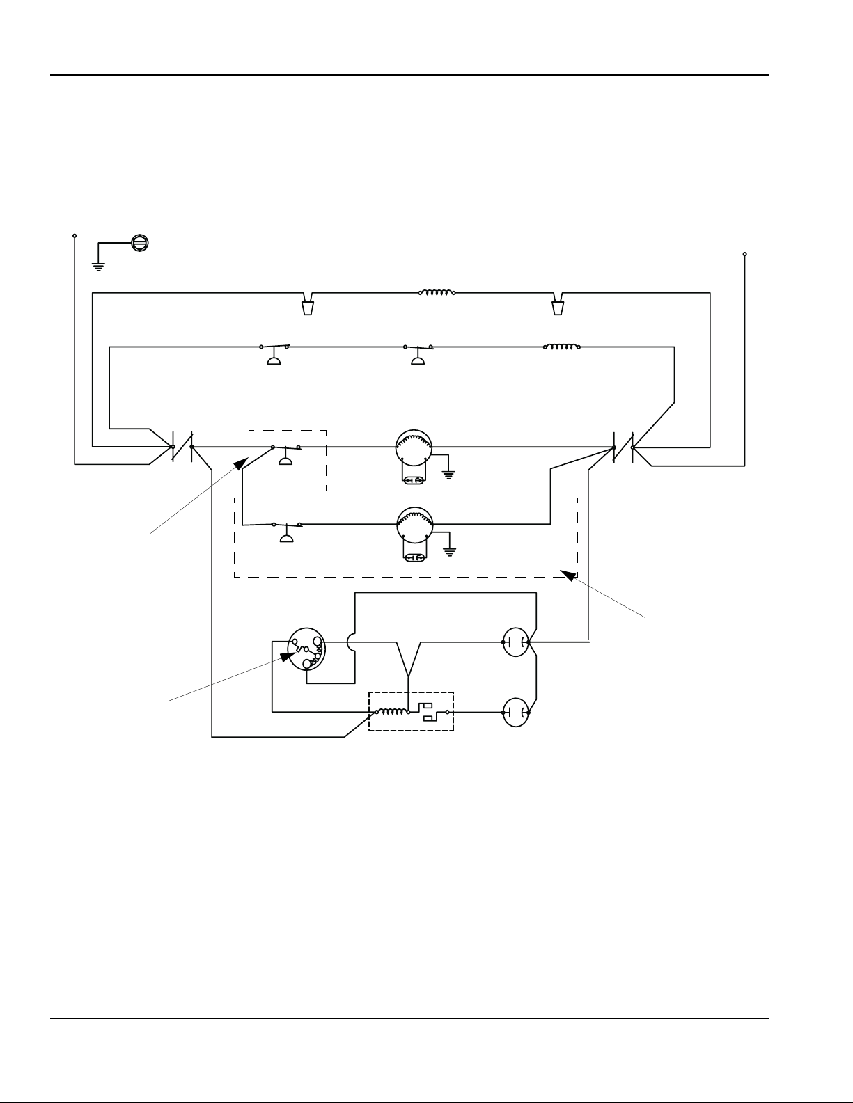
Electrical System Section 6
CONDENSING UNIT
CVD0675/CVD0875/CVD1075/CVD1285/CVD1475/CVD1476/CVD1875/CVD2075
208-230V/60Hz/1Ph or 230V/50Hz/1Ph
(Diagram Shown During Freeze Cycle)
L1
GROUND
(94)
COMPRESSOR
CRANKCASE
HEATER
(95)
L2 (N)
CONTACTOR
CONTACTS
*CVD675.CVD1476 DO
NOT HAVE A FAN
CYCLE CONTROL
*CVD1476 DOES NOT
HAVE A FAN MOTOR
*OVERLOAD
(96)
(85)
(97)
(43)
HIGH
PRESSURE
CUTOUT
FAN CYCLE
CONTROL
FAN CYCLE
CONTROL
COMPRESSOR
C
(74)
CONTACTOR
CONTACTOR
COIL
LOW
PRESSURE
SWITCH
FAN MOTOR
RUN CAPACITOR
FAN MOTOR
RUN CAPACITOR
(49)
RELAY
RUN CAPACITOR
(46)
(44)
START
CAPACITOR
S
(47)
R
(48)
52 1
COIL
CONTACTOR
CONTACTS
R
(45)
S
*CONDENSING UNITS
WITH TWO FANS ONLY
6-10
SV3096
Part No. 80-1206-3
Page 75

Section 6 Electrical System
CVD0675/CVD0875/CVD1075/CVD1285/CVD1475/CVD1476/CVD1875/CVD2075
208-230V/60Hz/3Ph
(Diagram Shown During Freeze Cycle)
L1
L2
L2L1 L3
T3T2COMPRESSOR
T1
L3
(96)
CONTACTOR
(85)
HIGH PRESSURE
CUTOUT
COMPRESSOR
CRANKCASE
HEATER
*CVD1475 & CVD2075 DO NOT USE A
COMPRESSOR CRANKCASE HEATER
LOW PRESSURE
SWITCH
FAN MOTOR
FAN CYCLE
CONTROL
RUN CAPACITOR
CONTACTOR
COIL
(95)(94)
(74)
*CVD675, CVD1476 DO NOT HAVE A FAN CYLE CONTROL
*CVD1476 DOES NOT HAVE A FAN MOTOR
(97)
FAN CYCLE
CONTROL
FAN MOTOR
RUN CAPACITOR
*CONDENSING
UNIT WITH TWO
FANS O NLY
SV3104
Part No. 80-1206-3 6-11
Page 76

Electrical System Section 6
Electronic Control Boards
AC LINE VOLTAGE
ELECTRICAL PLUG
AC LINE VOLTAGE
ELECTRICAL PLUG
CLEAN LIGHT
WATER LEVEL
PROBE LIGHT
BIN SWITCH
LIGHT
HARVEST LIGH
SAFETY LIMIT
CODE LIGHT
SV1588
7 AMP FUSE
AuCS PLUG
ICE THICKNESS
PROBE
WATER LEVEL
PROBE
DC LOW VOLTAGE
ELECTRICAL PLUG
1C
1B
1A
Q1400C
Green
Green
Red
SINGLE
DUAL
R-BIN SWITCH
LIGHT
L-BIN SWITCH
LIGHT
HARVEST LIGHT/
SAFETY LIMIT
CODE LIGHT
SINGLE OR DUAL
EVAPORATOR ICE
MACHINE SETTING
SV1587
MAIN FUSE
AuCS PLUG
ICE THICKNESS PROBE
(3/16” CONNECTION)
WATER LEVEL PROBE
DC LOW VOLTAGE
ELECTRICAL PLUG
Yello w
Green
Green
Red
1C
1F
1G
Q0600C/IB0600C/Q0800C/IB0800C/
Q1000C/IB1000C/SU1000C
AC LINE VOLTAGE
ELECTRICAL PLUG
MAIN FUSE
COOL VAPOR
SOLENOID PLUG
WATER PURGE
SETTING
ICE THICKNESS PROBE
WATER LEVEL PROBE
0
45
ICE/OFF/CLEAN
SWITCH PLUG
QDUALC
CURTAIN
SWITCH
PLUG
CLEAN LIGHT
HARVEST LIGHT
WATER LEVEL LIGHT
WATER FILL LIGHT
LIQUID LINE SOLENOID LIGHT
DUMP VALVE LIGHT
WATER PUMP LIGHT
CURTAIN SWITCH 2 LIGHT
COOL VAPOR SOLENOID 2 LIGHT
CURTAIN SWITCH 1 LIGHT
COOL VAPOR SOLENOID 1 LIGHT
SV1587A
6-12
Part No. 80-1206-3
Page 77

Section 6 Electrical System
Component Specifications and Diagnostics
CONTROL BOARD
All QuietQube® control boards incorporate the following
features. Refer to “Sequence of Operation” for additional
information specific to your model.
Harvest/Safety Limit Light
This light’s primary function is to be on as water contacts
the ice thickness probe during the freeze cycle, and
remain on throughout the entire harvest cycle. The light
will flicker as water splashes on the probes. The light’s
secondary function is to continuously flash when the ice
machine is shut off on a safety limit, and to indicate
which safety limit shut off the ice machine.
Freeze Time Lock-In Feature
The ice machine control system incorporates freeze time
lock-in feature. This prevents the ice machine from short
cycling in and out of harvest. The control board locks the
ice machine in the freeze cycle for six minutes. If the
water contacts the ice thickness probe during these six
minutes, the harvest light will come on (to indicate that
water is in contact with the probe), but the ice machine
will stay in the freeze cycle. After the six minutes are up,
a harvest cycle is initiated.
To allow the service technician to initiate a harvest cycle
without delay, this feature is not used on the first cycle
after moving the toggle switch OFF and back to ICE.
Maximum Freeze Time
The control system includes a built-in safety that will
automatically cycle the ice machine into harvest after 60
minutes in the freeze cycle.
Safety Limits
There are two safety limits that protect the ice machine if
the freeze or harvest cycles are outside of their
guidelines.
Three-Minute Delay
Q0600C/IB0600C/Q0800C/IB0800C/
Q1000C/IB1000C/SU1000C/QDUALC
The three-minute delay is initiated whenever the ice
machine cycles off (automatic shut-off) on a full bin.
The delay period starts when a water curtain is open for
7 continuous seconds in the harvest cycle.
• If the 3-minute delay period has expired, closure of
the water curtain will initiate an immediate start-up of
a freeze sequence.
• If the water curtain closes before the 3-minute delay
period has expired, the ice machine will start a freeze
sequence immediately after the 3-minute delay
period expires.
• The 3-minute delay period is over-ridden when the
toggle switch is moved to the OFF position, then
back to ICE.
Inputs
The control board, along with inputs, controls all
electrical components, including the ice machine
sequence of operation. Prior to diagnosing, you must
understand how the inputs affect the control board
operation. Refer to specific component specifications
(inputs), wiring diagrams and ice machine sequence of
operation sections for details. As an example, refer to
“Ice Thickness Probe” in the component specification
section of this manual for information relating to how the
probe and control board functions together.
Control Board Relays
The control board relays energize and de-energize
system components.
Relays are not field replaceable.
QDUALC Water Assist Harvest
Typical duration of a harvest sequence is less than 2.5
minutes, when the harvest sequence time reaches 4
minutes the following occurs: 4 minutes into a Harvest
Sequence. The water fill valve will energize to fill the
trough with water. 5 minutes into a Harvest Sequence.
The water pump will energize and water will flow over
the evaporators. The water fill valve and water pump
remain on until all bin switches have been activated, or
until the 7 minute Harvest Sequence time limit is
reached.
Part No. 80-1206-3 6-13
Page 78
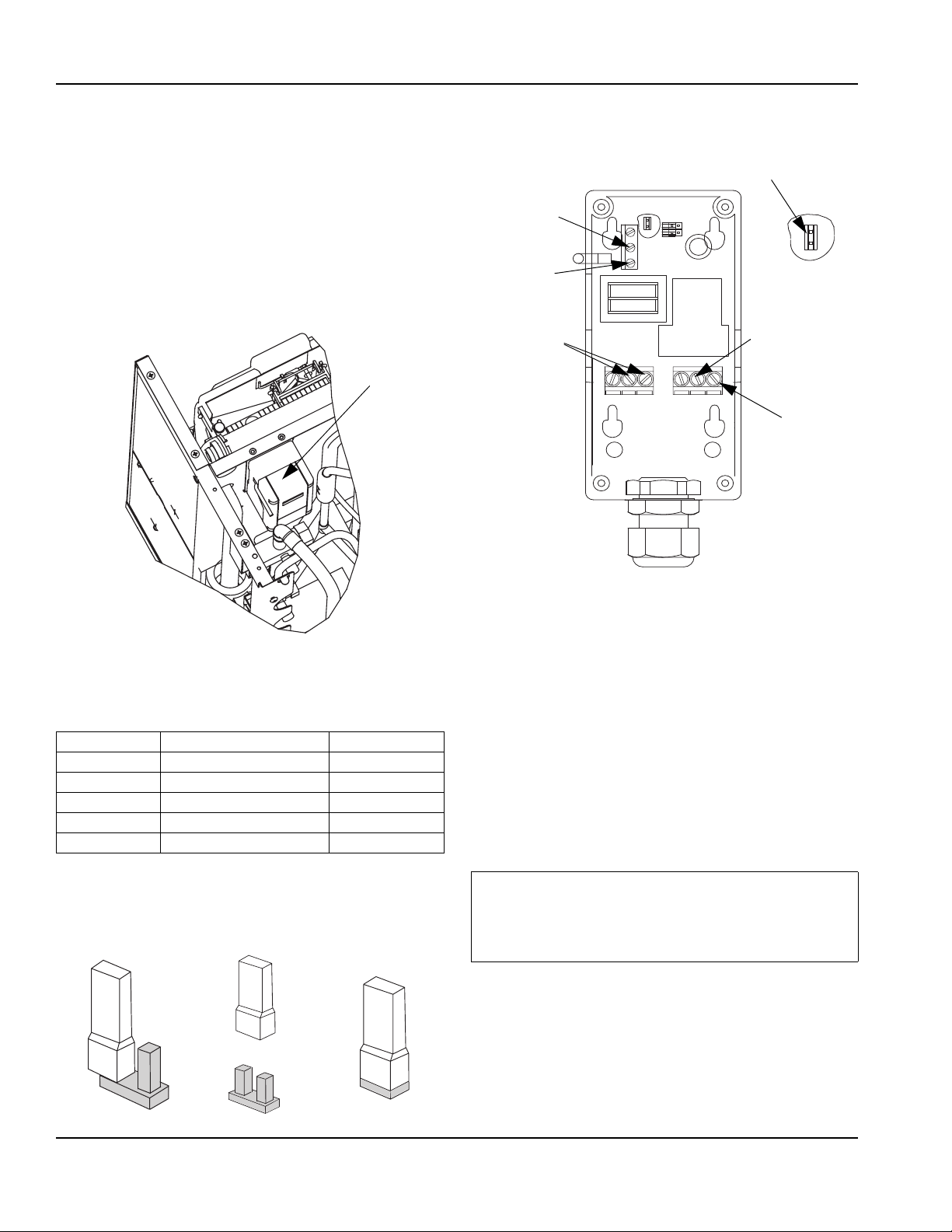
Electrical System Section 6
ELECTRONIC BIN THERMOSTAT
Function
The temperature control opens the bin switch circuit
when ice contacts the sensor. When ice no longer
contacts the sensor, the circuit closes and the ice
machine starts.
Specifications
Setpoint Range: -30 to 212°F (-34 - 100°C)
RED LEAD
SENSOR
PROBE
BLACK
LEAD
SENSOR
PROBE
P5
KEYPAD
JUMPER
LOCATION
P5
CONTROL
LOCATION
Control Location
CONTROL SETTINGS
Verify control is set properly before proceeding..
Display Function Preset Settings
SP Set Point 40
DIF Differential 1
ASD Anti-Short Cycle Delay 1
OFS Temperature Offset 0
SF Sensor Failure Mode 1
MATCH
WIRING
TO ICE
MACHINE
VOLTAGE
240V
COM
115V
C
NC
NO
RED LEAD
BIN SWITCH
or TOGGLE
SWITCH
WIRE
WHITE LEAD
BIN SWITCH
or TOGGLE
SWITCH
WIRE
Inside of Bin Thermostat Control
Setting Control Setpoint Value
To view and adjust setpoint, follow these steps:
1. Press MENU until the display flashes SP.
2. Press MENU again to display the existing setpoint
value.
3. Press Up or Down (arrows) to change the setpoint
value.
4. Press MENU again to save the new value. The
display returns to the sensed temperature.
NOTE: If no setup entry is made for 30 seconds, the
control reverts to the normal temperature display.
Positioning the Touchpad Jumper
The P5 jumper position determines if the touchpad is
locked or unlocked. The control is factory locked; to
unlock move the jumper from one pin to two pins.
6-14
Important
If MENU is not pressed after changing the setpoint
value, the control reverts to the previously
programmed setpoint value.
Part No. 80-1206-3
Page 79

Section 6 Electrical System
Differential, Anti-Short Cycle Delay, Temperature
Offset, or Sensor Failure Operation
To set or verify the Differential, Anti-Short Cycle Delay,
Temperature Offset or Sensor Failure Operation use the
following method.
Factory Preset Temperature Control Code Settings as
follows:
1. Press and hold MENU until the display changes to
flashing SP.
2. Press up and down (arrows) repeatedly until the
desired function is displayed.
3. Press MENU to display the function’s current value.
4. Press up and down (arrows) until the desired value
is displayed.
5. Press MENU to save the new value. The display
returns to the sensor temperature.
NOTE: If no setup entry is made for 30 seconds, the
control reverts to the temperature display.
NOTE: Any saved control settings are non-volatile and
remain in the control’s memory during power
interruptions.
Check Procedure
!
Warning
Line voltage is present inside control. Contact with
line voltage can cause serious injury or death.
If the control system does not function properly, verify
that the control is wired and set up properly. If the
problem persists use the following procedures to
determine the cause of the problem.
Important
Follow these troubleshooting procedures in the
order presented. Do not skip any of the steps in the
procedures.
1. Check the proper voltage to the control.
A. Remove the cover, loosen the four cover
screws.
D. If the voltage reading is not within the required
range, check the power source and input power
wires for problems.
2. Fault Codes
If the LCD displays an alarm or fault code (SF or EE):
Fault Code Definition Solution
SF flashing
alternately with OP
SF flashing
alternately with SH
EE Program failure Reset the control
Open
temperature
sensor or sensor
wiring
Shorted
temperture
sensor or sensor
wiring
See Step 3. Cycle
power to reset
control.
See Step 3. Cycle
power to reset
control.
by pressing MENU.
If problem persists,
replace the control.
3. Check for proper operation.
NOTE: Perform Steps 1 and 2 before performing this
step.
A. Disconnect the load from the output relay
terminals.
B. Reconnect the sensor leads and supply power
to the control.
C. Replace the cover.
D. Check the control settings for proper values.
E. Press and hold MENU until SP appears.
F. Press up and down (arrows) to change the
setpoint temperature above and below the
sensor temperature until the relay energizes and
de-energizes.
G. If the output relay does not perform as indicated
replace the control.
H. If proper operation of the control is verified,
reconnect the load.
B. Use an AC voltmeter to check the voltage
between the common and 120V or 240V
terminals.
C. The voltage must be between102 and 132 volts
for 120V applications, 177 and 264 volts for 208/
230V applications.
Part No. 80-1206-3 6-15
Page 80

Electrical System Section 6
MAIN FUSE
Function
The control board fuse stops ice machine operation if
electrical components fail causing high amp draw.
Specifications
The main fuse is 250 Volt, 7 amp.
Check Procedure
Warning
!
High (line) voltage is applied to the control board
(terminals #55 and #56) at all times. Removing the
control board fuse or moving the toggle switch to
OFF will not remove the power supplied to the
control board.
1. If the bin switch light is on with the water curtain
closed, the fuse is good.
Warning
!
Disconnect electrical power to the entire ice
machine before proceeding.
2. Remove the fuse. Check the resistance across the
fuse with an ohm meter.
BIN SWITCH
Function
Movement of the water curtain controls bin switch
operation. The bin switch has two main functions:
1. Terminating the harvest cycle and returning the ice
machine to the freeze cycle.
This occurs when the bin switch is opened and
closed again within 7 seconds during the harvest
cycle.
2. Automatic ice machine shut-off.
If the storage bin is full at the end of a harvest cycle,
the sheet of cubes fails to clear the water curtain and
holds it open. After the water curtain is held open for
7 seconds, the ice machine shuts off. The ice
machine remains off until enough ice is removed
from the storage bin to allow the sheet of cubes to
drop clear of the water curtain. As the water curtain
swings back to the operating position, the bin switch
closes and the ice machine restarts, provide the
three-minute delay has expired.
Important
The water curtain must be ON (bin switch(s) closed)
to start ice making.
Reading Result
Open (OL) Replace fuse
Closed (O) Fuse is good
Specifications
The bin switch is a magnetically operated reed switch.
The magnet is attached to the lower right corner of the
water curtain. The switch is attached to the evaporatormounting bracket.
The bin switch is connected to a varying D.C. voltage
circuit. (Voltage does not remain constant.)
NOTE: Because of a wide variation in D.C. voltage, it is
not recommended that a voltmeter be used to check bin
switch operation.
Check Procedure
1. Set the toggle switch to OFF.
2. Watch the bin switch light on the control board.
3. Move the water curtain toward the evaporator. The
bin switch must close. The bin switch light “on”
indicates the bin switch has closed properly.
4. Move the water curtain away from the evaporator.
The bin switch must open. The bin switch light “off”
indicates the bin switch has opened properly.
6-16
Part No. 80-1206-3
Page 81

Section 6 Electrical System
OHM Test
1. Disconnect the bin switch wires to isolate the bin
switch from the control board.
2. Connect an ohmmeter to the disconnected bin
switch wires.
3. Cycle the bin switch open and closed numerous
times by opening and closing the water curtain.
NOTE: To prevent misdiagnosis:
• Always use the water curtain magnet to cycle the
switch (a larger or smaller magnet will affect switch
operation).
• Watch for consistent readings when the bin switch is
cycled open and closed (bin switch failure could be
erratic).
Water Curtain Removal Notes
The water curtain must be on (bin switch closed) to start
ice making. While a freeze cycle is in progress, the water
curtain can be removed and installed at any time without
interfering with the electrical control sequence.
If the ice machine goes into harvest sequence while the
water curtain is removed, one of the following will
happen:
• Water curtain remains off:
When the harvest cycle time reaches 3.5 minutes
and the bin switch is not closed, the ice machine
stops as though the bin were full.
• Water curtain is put back on:
If the bin switch closes prior to reaching the 3.5minute point, the ice machine immediately returns to
another freeze sequence prechill.
Part No. 80-1206-3 6-17
Page 82

Electrical System Section 6
ICE/OFF/CLEAN TOGGLE SWITCH
Q0600C/IB0600C/Q0800C/IB0800C/
Q1000C/IB1000C/SU1000C/Q1400C
Function
The switch is used to place the ice machine in ICE, OFF
or CLEAN mode of operation.
Specifications
Double-pole, double-throw switch. The switch is
connected into a varying low D.C. voltage circuit.
Check Procedure
NOTE: Because of a wide variation in D.C. voltage, it is
not recommended that a volt meter be used to check
toggle switch operation.
1. Inspect the toggle switch for correct wiring.
2. Isolate the toggle switch by disconnecting all wires
from the switch, or by disconnecting the Molex
connector and removing wire #69 from the toggle
switch.
3. Check across the toggle switch terminals using a
calibrated ohm meter. Note where the wire numbers
are connected to the switch terminals, or refer to the
wiring diagram to take proper readings.
Switch Setting Te rminals Ohm Reading
66-62 Open
ICE
CLEAN
OFF
67-68 Closed
67-69 Open
66-62 Closed
67-68 Open
67-69 Closed
66-62 Open
67-68 Open
67-69 Open
4. Replace the toggle switch if ohm readings do not
match all three switch settings.
ICE/OFF/CLEAN TOGGLE SWITCH
QDUALC
Function
The switch is used to place the ice machine in ICE, OFF
or CLEAN mode of operation.
Specifications
Single-pole, single-throw switch. The switch is
connected into a varying low D.C. voltage circuit.
Check Procedure
NOTE: Because of a wide variation in D.C. voltage, it is
not recommended that a volt meter be used to check
toggle switch operation.
1. Inspect the toggle switch for correct wiring.
2. Isolate the toggle switch by disconnecting all wires
from the switch, or by disconnecting the Molex
connector and removing wire #69 from the toggle
switch.
3. Check across the toggle switch terminals using a
calibrated ohm meter. Note where the wire numbers
are connected to the switch terminals, or refer to the
wiring diagram to take proper readings.
Switch Setting Ter minals Ohm Reading
23-20 Open
ICE
CLEAN
OFF
23-24 Closed
23-19 Closed
20-23 Open
20-24 Closed
20-19 Closed
23-24 Open
23-19 Open
23-20 Open
4. Replace the toggle switch if ohm readings do not
match all three switch settings.
6-18
Part No. 80-1206-3
Page 83

Section 6 Electrical System
Ice Thickness Probe (Harvest Initiation)
HOW THE PROBE WORKS
Manitowoc’s electronic sensing circuit does not rely on
refrigerant pressure, evaporator temperature, water
levels or timers to produce consistent ice formation.
As ice forms on the evaporator, water (not ice) contacts
the ice thickness probe. After the water completes this
circuit across the probe continuously for 6-10 seconds, a
harvest cycle is initiated.
ICE THICKNESS CHECK
The ice thickness probe is factory-set to maintain the ice
bridge thickness at 1/8" (3.2 mm).
NOTE: Make sure the water curtain is in place when
performing this check. It prevents water from splashing
out of the water trough.
1. Inspect the bridge connecting the cubes. It should
be about 1/8" (3.2 mm) thick.
2. If adjustment is necessary, turn the ice thickness
probe adjustment screw clockwise to increase
bridge thickness, or counterclockwise to decrease
bridge thickness.
NOTE: Turning the adjustment 1/3 of a turn will change
the ice thickness about 1/16" (1.5 mm). The starting
point before final adjustment is approximately a 3/16”
gap. Place a 1/4” drill bit across the evaporator, then
adjust the ice thickness probe until the metal T touches
the drill bit. Test run and adjust until a 1/8” connecting
bridge is obtained
Ice Thickness Probe Cleaning
1. Mix a solution of Manitowoc ice machine cleaner
and water (2 ounces of cleaner to 16 ounces of
water) in a container.
2. Soak ice thickness probe in container of cleaner/
water solution while disassembling and cleaning
water circuit components (soak ice thickness probe
for 10 minutes or longer).
3. Clean all ice thickness probe surfaces including all
plastic parts (do not use abrasives). Verify the ice
thickness probe cavity is clean. Thoroughly rinse ice
thickness probe (including cavity) with clean water,
then dry completely. Incomplete rinsing and
drying of the ice thickness probe can cause
premature harvest.
4. Reinstall ice thickness probe, then sanitize all ice
machine and bin/dispenser interior surfaces.
ADJUSTING SCREW
1/8” ICE BRIDGE
THICKNESS
SV3114
Ice Thickness Check
Make sure the ice thickness probe wire and the bracket
do not restrict movement of the probe.
Part No. 80-1206-3 6-19
Page 84

Electrical System Section 6
DIAGNOSING ICE THICKNESS CONTROL CIRCUITRY
Ice Machine Does Not Cycle Into Harvest When Water Contacts The Ice Thickness Control Probe
Step 1 Bypass the freeze time lock-in feature by moving the ICE/OFF/CLEAN switch to OFF and back to ICE. Wait
until the water starts to flow over the evaporator.
Step 2 Clip the jumper wire leads to the ice thickness probe and any cabinet ground.
EVAPORATOR
ICE THICKNESS PROBE
1C
GROUND
JUMPER WIRE
CLEAN LIGHT
WATER LEVEL LIGHT
BIN SWITCH LIGHT
HARVEST/SAFETY LIMIT LIGHT
SV3010
Step 2
Step 2 Jumper wire connected from probe to ground
Monitoring of Harvest Light Correction
The harvest light comes on, and 6-10 seconds later, ice
machine cycles from freeze to harvest.
The harvest light comes on but the ice machine stays in the
freeze sequence.
The ice thickness control circuitry is functioning properly. Do
not change any parts.
The ice thickness control circuitry is functioning properly. The
ice machine is in a six-minute freeze time lock-in. Verify step 1
of this procedure was followed correctly.
The harvest light does not come on. Proceed to Step 3, below.
Step 3 Disconnect the ice thickness probe from the control board at terminal 1C. Clip the jumper wire leads to
terminal 1C on the control board and any cabinet ground. Monitor the harvest light.
ICE THICKNESS PROBE
EVAPORATOR
GROUND
JUMPER
WIRE
CLEAN LIGHT
WATER LEVEL LIGHT
BIN SWITCH LIGHT
HARVEST/SAFETY LIMIT LIGHT
1C
SV1588G
SV3011
Step 3
Step 3 Jumper wire connected from control board terminal 1C to ground
Monitoring of Harvest Light Correction
The harvest light comes on, and 6-10 seconds later, ice
The ice thickness probe is causing the malfunction.
machine cycles from freeze to harvest.
The harvest light comes on but the ice machine stays in the
freeze sequence.
The control circuitry is functioning properly. The ice machine is
in a six-minute freeze time lock-in (verify step 1 of this
procedure was followed correctly).
The harvest light does not come on. The control board is causing the malfunction.
6-20
Part No. 80-1206-3
Page 85

Section 6 Electrical System
Ice Machine Cycles Into Harvest Before Water Contact With The Ice Thickness Probe
Step 1 Bypass the freeze time lock-in feature by moving the ICE/OFF/CLEAN switch to OFF and back to ICE. Wait
until the water starts to flow over the evaporator, then monitor the harvest light.
Step 2 Disconnect the ice thickness probe from the control board at terminal 1C.
ICE THICKNESS PROBE
EVAPORATOR
Step 2
Step 2 Disconnect probe from control board terminal 1C.
Monitoring of Harvest Light Correction
The harvest light stays off and the ice machine remains in the
freeze sequence.
The harvest light comes on, and 6-10 seconds later, the ice
machine cycles from freeze to harvest.
CLEAN LIGHT
WATER LEVEL LIGHT
BIN SWITCH LIGHT
HARVEST/SAFETY LIMIT LIGHT
1C
SV3011
The ice thickness probe is causing the malfunction.
Verify that the Ice Thickness probe is adjusted correctly.
The control board is causing the malfunction.
Part No. 80-1206-3 6-21
Page 86

Electrical System Section 6
Water Level Control Circuitry
WATER LEVEL PROBE LIGHT
The water level probe circuit can be monitored by
watching the water level light. The water level light is on
when water contacts the probe, and off when no water is
in contact with the probe. The water level light functions
any time power is applied to the ice machine, regardless
of toggle switch position.
FREEZE CYCLE CIRCUITRY
Q0600C/IB0600C/Q0800C/IB0800C
Q1000C/IB1000C/QDUALC
Manitowoc’s electronic sensing circuit does not rely on
float switches or timers to maintain consistent water
level control. During the freeze cycle, the water inlet
valve energizes (turns on) and de-energizes (turns off) in
conjunction with the water level probe located in the
water trough.
During the first 45 seconds of the Freeze Cycle:
• The water inlet valve is on when there is no water in
contact with the water level probe.
• The water inlet valve turns off after water contacts
the water level probe for 3 continuous seconds.
• The water inlet valve will cycle on and off as many
times as needed to fill the water trough.
After 45 seconds into the Freeze Cycle:
The water inlet valve will cycle on, and then off one more
time to refill the water trough. The water inlet valve is
now off for the duration of the freeze sequence.
HARVEST CYCLE CIRCUITRY
The water level probe does not control the water inlet
valve during the harvest cycle. During the harvest cycle
water purge, the water inlet valve energizes (turns on)
and de-energizes (turns off) strictly by time. The harvest
water purge adjustment dial may be set at 15, 30 or 45
seconds.
SV1616A
Freeze Cycle Water Level Setting
During the freeze cycle, the water level probe is set to
maintain the proper water level above the water pump
housing. The water level is not adjustable. If the water
level is incorrect, check the water level probe for
damage (probe bent, etc.). Repair or replace the probe
as necessary.
WATER INLET VALVE SAFETY SHUT-OFF
In the event of a water level probe failure, this feature
limits the water inlet valve to a six-minute on time.
Regardless of the water level probe input, the control
board automatically shuts off the water inlet valve if it
remains on for 6 continuous minutes. This is important to
remember when performing diagnostic procedures on
the water level control circuitry.
6-22
CONTROL BOARD
HARVEST
WATER PURGE
ADJUSTMENT
30
15
45
SV1617
NOTE: The water purge must be at the factory setting
of 45 seconds for the water inlet valve to energize during
the last 15 seconds of the Water Purge. If set at 15 or 30
seconds the water inlet valve will not energize during the
harvest water purge.
Part No. 80-1206-3
Page 87

Section 6 Electrical System
DIAGNOSING WATER LEVEL CONTROL
CIRCUITRY
Q0600C/IB0600C/Q0800C/IB0800C/Q1000C/IB1000C/QDUAL
Problem: Water Trough Overfilling During The
Freeze Cycle
Step 1 Start a new freeze sequence by moving the ICE/
OFF/CLEAN toggle switch to OFF, then back to ICE.
Step 2 Wait until the freeze cycle starts
(approximately 45 seconds, the freeze cycle starts when
the compressor energizes) then connect a jumper from
the water level probe to any cabinet ground.
Important
This restart must be done prior to performing
diagnostic procedures. This assures the ice
machine is not in a freeze cycle water inlet valve
safety shut-off mode. You must complete the entire
diagnostic procedure within 6 minutes of starting.
Important
For the test to work properly you must wait until the
freeze cycle starts, prior to connecting the jumper
wire. If you restart the test you must disconnect the
jumper wire, restart the ice machine, (step 1) and
then reinstall the jumper wire after the compressor
starts.
YELLOW
GREEN
GREEN
RED
1C
1F
CLEAN LIGHT
WATER LEVEL LIGHT
BIN SWITCH LIGHT
HARVEST/SAFETY LIMIT LIGHT
GROUND
JUMPER
SV1621A
Step 2
Step 2 Jumper wire connected from probe to ground
Is water flowing into the
water trough?
no on De-Energized This is normal operation.
yes on De-Energized The water inlet valve is
yes off Energized Proceed to step 3.
Part No. 80-1206-3 6-23
The Water Level Light is:
The Water Inlet Valve
Solenoid Coil is:
Cause
Do not change any parts.
causing the problem.
Continued on next page …
Page 88

Electrical System Section 6
Problem: Water Trough Overfilling During The
Freeze Cycle (continued)
Step 3 Allow ice machine to run. Disconnect the water
level probe from control board terminal 1F, and connect
a jumper wire from terminal 1F to any cabinet ground.
1
GROUND
JUMPER WIRE
SV1588G
1C
1F
1G
Remember if you are past 6 minutes from starting, the
ice machine will go into a freeze cycle water inlet valve
safety shut-off mode, and you will be unable to complete
this test. If past 6 minutes you must restart this test by
disconnecting the jumper wire, restarting the ice
machine, (step 1) and then reinstalling the jumper wire to
terminal 1F, after the compressor starts.
Yellow
Green
Green
Red
CLEAN LIGHT
WATER LEVEL LIGHT
BIN SWITCH LIGHT
HARVEST/SAFETY LIMIT LIGHT
SV1588
Is water flowing into
the water trough?
NO ON De-Energized
YES OFF Energized The control board is causing the problem.
YES ON De-Energized The water fill valve is causing the problem.
Step 3
Step 3 Jumper wire connected from control board terminal 1F to ground
The Water Level
Light is:
The Water Inlet Valve
Solenoid Coil is:
Cause
The water level probe is causing the problem.
Clean or replace the water level probe.
6-24
Part No. 80-1206-3
Page 89

Section 6 Electrical System
Problem: Water Will Not Run Into The Sump Trough
During The Freeze Cycle
Step 1 Verify water is supplied to the ice machine, and
then start a new freeze sequence by moving the ICE/
OFF/CLEAN toggle switch to OFF then back to ICE.
Important
This restart must be done prior to performing
diagnostic procedures. This assures the ice machine
is not in a freeze cycle water inlet valve safety shutoff mode. You must complete the entire diagnostic
procedure within 6 minutes of starting.
Step 2 Checking for normal operation
Is water flowing into
the water trough?
Yes Off Energized This is Normal Operation don’t change any parts
No On or Off Energized Or De-Energized Proceed to step 3
Step 3 Leave the ice machine run, then disconnect the
water level probe from control board terminal 1F.
The Water Level
Light is:
The Water Inlet Valve
Solenoid Coil is:
Step 2 Wait until the freeze cycle starts (approximately
45 seconds, the freeze cycle starts when the
compressor energizes), and then refer to chart.
Cause
Important
For the test to work properly you must wait until the
freeze cycle starts, prior to disconnecting the water
level probe. If you restart the test you must
reconnect the water level probe, restart the ice
machine, (step 1) and then disconnect the water
level probe after the compressor starts.
Is water flowing into
the water trough?
Yes Off Energized The water level probe is causing the problem.
No Off Energized The water inlet valve is causing the problem.
No On or Off De-Energized The control board is causing the problem.
DISCONNECT
WATER LEVEL
PROBE FROM
TERMINAL 1F
SV1621G SV1588
Step 3
Step 3 Disconnect water level probe from control board terminal 1F
The Water Level
Light is:
The Water Inlet Valve
Solenoid Coil is:
Clean or replace the water level probe.
CLEAN LIGHT
WATER LEVEL LIGHT
BIN SWITCH LIGHT
HARVEST/SAFETY LIMIT LIGHT
Cause
Part No. 80-1206-3 6-25
Page 90

Electrical System Section 6
Diagnosing An Ice Machine That Will Not
Run
ICE MACHINE HEAD SECTION
Q0600C/IB0600C/Q0800C/IB800C/
Q1000C/IB1000C/SU1000C/Q1400C/QDUALC
Warning
!
High (line) voltage is applied to the control board
(terminals #55 and #56) at all times. Removing
control board fuse or moving the toggle switch to
OFF will not remove the power supplied to the
control board.
If the water pump is energized but no ice is produced
refer to condensing unit will not run.
1. Verify primary voltage is supplied to ice machine
head section and the fuse/circuit breaker is closed.
2. Verify control board fuse is okay. If the bin switch or
water level probe light functions, the fuse is okay.
3. Verify all bin switches function properly. A defective
bin switch can falsely indicate a full bin of ice.
4. Verify ICE/OFF/CLEAN toggle switch functions
properly. A defective toggle switch may keep the ice
machine in the OFF mode.
5. Verify low DC voltage is properly grounded. Loose
DC wire connections may intermittently stop the ice
machine.
Diagnosing A Condensing Unit That Will
Not Run
CONDENSING UNIT
CVD0675/CVD0875/CVD1075/CVD1285/
CVD1475/CVD1875/CVD2075
If the ice machine water pump is not energized refer to
“Ice Machine Head Section Will Not Run”.
1. Verify primary voltage is supplied to ice machine
condensing unit and the fuse/circuit breaker is
closed.
2. Verify the high-pressure cutout and low-pressure
cutouts are closed. The HPCO and LPCO are
closed if primary line voltage is present at the
contactor coil terminals.
3. Verify line voltage is present at the contactor coil.
4. Verify the contactor contacts are closed and line
voltage is present across all lines.
5. Refer to compressor diagnostics.
6. Replace the control board.
Be sure Steps 1-5 were followed thoroughly. Intermittent
problems are not usually related to the control board.
6-26
Part No. 80-1206-3
Page 91

Section 6 Electrical System
COMPRESSOR ELECTRICAL DIAGNOSTICS
The compressor will not start or will trip repeatedly
on overload.
Check Resistance (Ohm) Values
NOTE: Compressor windings can have very low ohm
values. Use a properly calibrated meter.
Perform the resistance test after the compressor cools.
The compressor dome should be cool enough to touch
(below 120°F/49°C) to assure that the overload is closed
and the resistance readings will be accurate.
SINGLE PHASE COMPRESSORS
1. Disconnect power from the condensing unit and
remove the wires from the compressor terminals.
2. The resistance values must be within published
guidelines for the compressor. The resistance
values between C and S and between C and R,
when added together, should equal the resistance
value between S and R.
3. If the overload is open, there will be a resistance
reading between S and R, and open readings
between C and S and between C and R. Allow the
compressor to cool, then check the readings again.
THREE PHASE COMPRESSORS
1. Disconnect power from the condensing unit and
remove the wires from the compressor terminals.
Determine if the Compressor is Seized
Check the amp draw while the compressor is trying to
start.
COMPRESSOR DRAWING LOCKED ROTOR
The two likely causes of this are:
• Defective starting component
• Mechanically seized compressor
To determine which you have:
1. Install high and low side gauges.
2. Try to start the compressor.
3. Watch the pressures closely.
A. If the pressures do not move, the compressor is
seized. Replace the compressor.
B. If the pressures move, the compressor is turning
slowly and is not seized. Check the capacitors
and start relay.
COMPRESSOR DRAWING HIGH AMPS
The continuous amperage draw on start-up should not
be near the maximum fuse size indicated on the serial
tag.
The voltage when the compressor is trying to start must
be within ±10% of the nameplate voltage.
2. The resistance values must be within published
guidelines for the compressor. The resistance
values between L1 and L2, between L2 and L3, and
between L3 and L1 should all be equal.
3. If the overload is open, there will be open readings
between L1 and L2, between L2 and L3, and
between L3 and L1. Allow the compressor to cool,
then check the readings again.
Check Motor Windings to Ground
Check continuity between all three terminals and the
compressor shell or copper refrigeration line. Scrape
metal surface to get good contact. If continuity is
present, the compressor windings are grounded and the
compressor should be replaced.
Part No. 80-1206-3 6-27
Page 92

Electrical System Section 6
Diagnosing Start Components
If the compressor attempts to start, or hums and trips the
overload protector, check the start components before
replacing the compressor.
CAPACITOR
• Visual evidence of capacitor failure can include a
bulged terminal end or a ruptured membrane. Do not
assume a capacitor is good if no visual evidence is
present.
• A good test is to install a known good substitute
capacitor.
• Use a capacitor tester when checking a suspect
capacitor. Clip the bleed resistor off the capacitor
terminals before testing.
RELAY
The relay has a set of contacts that connect and
disconnect the start capacitor from the compressor start
winding. The contacts on the relay are normally closed
(start capacitor in series with the start winding). The
relay senses the voltage generated by the start winding
and opens the contacts as the compressor motor starts.
The contacts remain open until the compressor is deenergized.
Warning
!
Disconnect electrical power to the condensing unit
before proceeding.
Relay Operation Check
1. Disconnect wires from relay terminals.
2. Verify the contacts are closed. Measure the
resistance between terminals 1 and 2. No continuity
indicates open contacts. Replace the relay.
3. Check the relay coil. Measure the resistance
between terminals 2 and 5. Not resistance indicates
an open coil. Replace the relay.
6-28
Part No. 80-1206-3
Page 93

QuietQube® Tubing Schematic
Q0600C/Q0800C/Q1000C
Section 7
Refrigeration System
Condensing Unit
SUCTION
SHUT-OFF
VALV E
SUCTION LINE
FILTER
ACCUMULATOR
S TRAP
REQUIRED
21’ OR
GREATER
RISE
COMPRESSOR
HEAD
PRESSURE
CONTROL
VALV E
Ice Machine Head Section
CONDENSER
LIQUID LINE
SHUT-OFF
VALV E
EVAPORATOR
HEAT EXCHANGER
TXV
CO OL VA P OR VA LV E
LLSV
DRIER
CHECK VALVE
RECEIVER
SERVICE
VALV E
RECEIVER
SV3099
Part No. 80-1206-3 7-1
Page 94

Refrigeration System Section 7
IB0600C/IB0800C/IB1000C/SU1000C
Condensing Unit
SUCTION LINE
S TRAP
REQUIRED
21’ OR
GREATER
RISE
FILTER
ACCUMULATOR
COMPRESSOR
HEAD
PRESSURE
CONTROL
VALV E
CONDENSER
SUCTION
SHUT-OFF
VALV E
LLSV
DRIER
Ice Machine Head Section
HEAT EXCHANGER
RECEIVER
SERVICE
VALV E
COOL VAPOR VALVE
RECEIVERS
TXV
CHECK VALVE
EVAPORATOR
LIQUID LINE
SHUT-OFF
VALV E
SV3098
7-2
Part No. 80-1206-3
Page 95

Section 7 Refrigeration System
Q1400C/QDUALC
Condensing Unit
SUCTION
SHUT-OFF
VALV E
SUCTION FILTER
ACCUMULATOR
S TRAP
REQUIRED
21’ OR
GREATER
RISE
COMPRESSOR
HEAD
PRESSURE
CONTROL
VALV E
CONDENSER
Ice Machine Head Section
CVD1476 ONLY
WATER REGULATING
VALV E
CVD1476 ONLY
CONDENSER WATER
OUTLET
LIQUID LINE
SHUT-OFF
VALV E
HEAT EXCHANGER
LLSV
DRIER
RECEIVER
SERVICE
VALV E
EVAPORATOR
COOL
VAP OR
VALV E
TXV
RECEIVER
COOL
VAP OR
VALV E
EVAPORATOR
CHECK VALVE
SV3097
Part No. 80-1206-3 7-3
Page 96

Refrigeration System Section 7
Refrigeration System Diagnostics
GENERAL
Verify the water and electrical systems are functioning
properly before diagnosing the refrigeration system or
it’s components.
A dirty evaporator increases the length of the harvest
cycle and will cause the ice machine to shut off on safety
limit #2. All Manitowoc ice machines must have their
evaporator(s) cleaned first, if safety limit #2 is in
memory.
REFRIGERATION SYSTEM OPERATION
Freeze Cycle
The compressor sends high pressure, high temperature
gas to the condenser.
Air-Cooled Models
fan cycle control cut in set point and the condenser fan
motor(s) energizes. The condenser removes heat and
the refrigerant condenser to a high pressure liquid. The
head pressure control valve will modulate to maintain
the correct head pressure and refrigerant temperature.
Water-Cooled Models
modulates from the bypass position to the non-bypass
position as the head pressure exceeds its set point. The
condenser removes heat and the refrigerant condenses
to a high pressure liquid. The water regulating valve will
modulate to maintain the correct head pressure and
refrigerant temperature.
- Discharge pressure will exceed the
- The head pressure control valve
The refrigerant enter the ice machine head section and
is store in the receiver. Liquid refrigerant leaves the
receiver through a dip tube and passes through the line
drier and liquid line solenoid valve. The refrigerant then
passes through the heat exchanger where the liquid is
sub-cooled before delivery to the TXV. The liquid
refrigerant passes through the expansion valve orifice
and enters the evaporator as a low pressure saturated
vapor. As the refrigerant leaves the evaporator and
passes through the heat exchanger absorbing additional
heat from the liquid line. The suction vapor returns to the
condensing unit, passes through the suction
accumulator and enters the compressor.
Harvest Cycle
The head pressure control valve bypasses the
condenser and sends compressor discharge gas directly
to the receiver. The discharge gas keeps the receiver
warm and the refrigerant pressure up as liquid
refrigerant is boiled off the receiver. Vapor from the top
of the receiver flows through the cool vapor valve and
condenses in the evaporator. The change of state of the
refrigerant from vapor to liquid releases the heat
necessary for the harvest cycle. The refrigerant returns
to the condensing unit and enters the suction
accumulator. Vapor refrigerant is returned to the
compressor.
7-4
Part No. 80-1206-3
Page 97

Section 7 Refrigeration System
Suction Accumulator Operation
Liquid refrigerant collects in the suction accumulator
during the harvest cycle and is removed during the
freeze cycle. The liquid refrigerant is returned to the
compressor through a screen and orifice in the suction
accumulator J tube. Passing the liquid through the orifice
causes a pressure drop; the liquid flashes to a vapor and
creates a refrigeration affect. It is normal to see frost on
the accumulator, suction line and compressor suction
port in the freeze cycle. The suction accumulator
empties within the first 6 minutes of the freeze cycle.
When the refrigeration affect ends (liquid refrigerant has
been removed), the suction line between the
accumulator and compressor will increase in
temperature. The suction line temperature increases 20
plus degrees 2 minutes after the liquid has been
removed. The time needed to remove the liquid
refrigerant will vary with the ambient temperature and
the length of the harvest cycle. Higher ambient
temperatures = shorter harvest cycles, faster removal of
liquid refrigerant from the accumulator and greater
suction line temperature increases.
Refrigerant Charge
Refrigerant charge on QuietQube® ice machines is very
important. Overcharged or undercharged machines will
normally fail in the harvest cycle (produces even sheets
of ice, but will not harvest).
• Undercharged ice machines run out of liquid
refrigerant in the receiver during harvest. This
increases the harvest cycle time and results in a
safety limit #2 failure.
• Overcharged ice machines sub cool the liquid
refrigerant in the receiver during the freeze cycle.
resulting in a refrigerant boil off rate in the harvest
cycle that is too low. This increases the harvest cycle
time and results in a safety limit #2 failure.
• When you are replacing refrigeration system
components, verify refrigerant charge is correct by
weighing amount recovered. Incorrect refrigerant
charge will result in component misdiagnosis.
Part No. 80-1206-3 7-5
Page 98

Refrigeration System Section 7
BEFORE BEGINNING SERVICE
Ice machines may experience operational problems only
during certain times of the day or night. A machine may
function properly while it is being serviced, but
malfunctions later. Information provided by the user can
help the technician start in the right direction, and may
be a determining factor in the final diagnosis.
Ask these questions before beginning service:
• When does the ice machine malfunction? (night, day,
all the time, only during the freeze cycle, etc.)
• When do you notice low ice production? (one day a
week, every day, on weekends, etc.)
• Can you describe exactly what the ice machine
seems to be doing?
• Has anyone been working on the ice machine?
• Is anything (such as boxes) usually stored near or on
the ice machine which could obstruct airflow around
the machine?
• During “store shutdown,” is the circuit breaker, water
supply or air temperature altered?
• Is there any reason why incoming water pressure
might rise or drop substantially?
ICE PRODUCTION CHECK
The amount of ice a machine produces directly relates to
the operating water and air temperatures. This means
an ice machine in a 70°F (21.2°C) room with 50°F
(10.0°C) water produces more ice than the same model
ice machine in a 90°F (32.2°C) room with 70°F (21.2°C)
water.
1. Determine the ice machine operating conditions:
Air temp. entering condenser: _______ °
Air temp. around ice machine: _______ °
Water temp. entering sump trough: _______ °
2. Refer to the appropriate 24 Hour Ice Production
Chart. Use the operating conditions determined in
Step 1 to find published 24 hour ice production:
______
3. Perform an actual ice production check. Use the
formula below.
1.
2.
3.
__________
Freeze Time
1440
Minutes in 24
Hours
__________
Weight of One
Harvest
+ __________
Harvest Time
÷ __________
Total Cycle Time
x __________
Cycles Per Day
= __________
Total Cycle Time
= __________
Cycles Per Day
= __________
Actual 24 Hour Ice
Production
Important
Times are in minutes.
Example: 1 min., 15 sec. converts to 1.25 min.
(15 seconds ÷ 60 seconds = .25 minutes)
Weights are in pounds.
Example: 2 lb., 6 oz. converts to 2.375 lb.
(6 oz. ÷ 16 oz. = .375 lb.)
Weighing the ice is the only 100% accurate
check. However, if the ice pattern is normal and the
1/8" thickness is maintained, the ice slab weights
listed with the 24 Hour Ice Production Charts may
be used.
4. Compare the results of step 3 with step 2. Ice
production is normal when these numbers match
closely. If they match closely, determine if:
• another ice machine is required.
• more storage capacity is required.
7-6
• relocating the existing equipment to lower the
load conditions is required.
Contact the local Manitowoc distributor for
information on available options and accessories.
Part No. 80-1206-3
Page 99

Section 7 Refrigeration System
INSTALLATION/VISUAL INSPECTION CHECKLIST WATER SYSTEM CHECKLIST
A water-related problem often causes the same
Possible Problem Corrective Action
Ice machine is not level Level the ice machine
Condenser is dirty Clean the condenser
Water filtration is plugged (if
used)
Water drains are not run
separately and/or are not
vented
Line set is improperly
installed
Install a new water filter
Run and vent drains
according to the Installation
Manual
Reinstall according to the
Installation Manual
symptoms as a refrigeration system component
malfunction.
Example: A water dump valve leaking during the freeze
cycle, a system low on charge, and a starving TXV have
similar symptoms.
Water system problems must be identified and
eliminated prior to replacing refrigeration components.
Possible Problem Corrective Action
Water area (evaporator) is
dirty
Water inlet pressure not
between 20 and 80 psi
Incoming water temperature
is not between 35°F (1.7°C)
and 90°F (32.2°C).
Water filtration is plugged (if
used)
Water dump valve leaking
during the freeze cycle
Vent tube is not installed on
water outlet drain
Hoses, fittings, etc., are
leaking water
Water fill valve is stuck open Clean/replace as needed
Water is spraying out of the
sump trough area
Uneven water flow across the
evaporator
Water is freezing behind the
evaporator
Plastic extrusions and
gaskets are not secured to
the evaporator
Water does not flow over the
evaporator (not trickle)
immediately after the prechill
Clean as needed
Install a water regulator valve
or increase the water
pressure
If too hot, check the hot water
line check valves in other
store equipment
Install a new water filter
Clean/replace dump valve as
needed
See Installation Instructions
Repair/replace as needed
Stop the water spray
Clean the ice machine
Correct the water flow
Remount/replace as needed
Clean/replace water level
probe as needed
Part No. 80-1206-3 7-7
Page 100

Refrigeration System Section 7
ICE FORMATION PATTERN
Evaporator ice formation pattern analysis is helpful in ice
machine diagnostics.
Analyzing the ice formation pattern alone cannot
diagnose an ice machine malfunction. However, when
this analysis is used along with Manitowoc’s
Refrigeration System Operational Analysis Table, it can
help diagnose an ice machine malfunction.
Improper ice formation can be caused by any number of
problems.
Example: An ice formation that is “extremely thin at the
evaporator outlet” could be caused by a hot water
supply, a dump valve leaking water, a faulty water fill
valve, a low refrigerant charge, etc.
Important
Keep the water curtain in place while checking the
ice formation pattern to ensure no water is lost.
Evaporator Tubing Routing
Q0600C/IB0600C/Q0800C/IB0800C/Q1400C/QDUALC
Routing of the tubing on the back of the evaporator
determines the ice fill pattern failure mode. The
evaporator outlet tubing does not exit directly at the top
of the evaporator, but exits several inches below the top
of the evaporator. Extremely Thin at the Evaporator
Outlet will first be visible several inches below the top of
the evaporator. Extremely Thin at the Evaporator Inlet
will first be visible at the bottom of the evaporator.
OUTLET
OUTLET
IB1000C ONLY
Tubing routing for the IB1000C evaporator is different.
The evaporator outlet is at the bottom of the evaporator.
Extremely Thin at the Evaporator Outlet will first be
visible at the bottom and then the right side of the
evaporator. Extremely Thin at the Evaporator Inlet will
first be visible several inches above the bottom of the
evaporator.
v
INLET
OUTLET
SV3101
Thin at Outlet
SV3102
SV3103
Thin at Inlet
1. Normal Ice Formation
Ice forms across the entire evaporator surface.
At the beginning of the freeze cycle, it may appear that
more ice is forming at the evaporator inlet, than at the
evaporator outlet. At the end of the freeze cycle, ice
formation at the outlet will be close to, or just a bit thinner
than, ice formation at the inlet. The dimples in the cubes
at the outlet of the evaporator may be more pronounced
than those at the inlet. This is normal.
The ice thickness probe must be set to maintain the ice
bridge thickness at approximately 1/8". If ice forms
uniformly across the evaporator surface, but does not
reach 1/8" in the proper amount of time, this is still
considered normal.
INLET
7-8
SV1576
Thin at Outlet
Refer to Ice Thickness Probe Adjustment.
INLET
SV1575
Thin at Inlet
Part No. 80-1206-3
 Loading...