

Page 1
Koolaire Ice Machines
UnderCounter Models
lnstallation, Operation and Maintenance Manual
Part Number 040004686 8/15
Page 2

Section 1
General Information
Model Numbers . . . . . . . . . . . . . . . . . . . . . . . . . . . . . . . . . . . . . . . . . . . . . . . . . . . . . 4
Accessories . . . . . . . . . . . . . . . . . . . . . . . . . . . . . . . . . . . . . . . . . . . . . . . . . . . . . . . 4
Section 2
Installation Instructions
Location of Ice Machine . . . . . . . . . . . . . . . . . . . . . . . . . . . . . . . . . . . . . . . . . . . . . . 5
Ice Machine Heat of Rejection . . . . . . . . . . . . . . . . . . . . . . . . . . . . . . . . . . . . . . . . . 5
Leveling the Ice Machine . . . . . . . . . . . . . . . . . . . . . . . . . . . . . . . . . . . . . . . . . . . . . 5
Electrical Service . . . . . . . . . . . . . . . . . . . . . . . . . . . . . . . . . . . . . . . . . . . . . . . . . . . 6
Water Service/Drains . . . . . . . . . . . . . . . . . . . . . . . . . . . . . . . . . . . . . . . . . . . . . . . . 7
Water Supply and Drain Line Sizing/Connections . . . . . . . . . . . . . . . . . . . . . . . . 8
Before Starting the Ice Machine . . . . . . . . . . . . . . . . . . . . . . . . . . . . . . . . . . . . . . . 9
Installation Checklist . . . . . . . . . . . . . . . . . . . . . . . . . . . . . . . . . . . . . . . . . . . . . . . . 9
Table of Contents
Bin Caster . . . . . . . . . . . . . . . . . . . . . . . . . . . . . . . . . . . . . . . . . . . . . . . . . . . . . 4
Arctic Pure Water Filter System . . . . . . . . . . . . . . . . . . . . . . . . . . . . . . . . . . . . . 4
Manitowoc Cleaner and Sanitizer . . . . . . . . . . . . . . . . . . . . . . . . . . . . . . . . . . . 4
General . . . . . . . . . . . . . . . . . . . . . . . . . . . . . . . . . . . . . . . . . . . . . . . . . . . . . . . 6
Voltage . . . . . . . . . . . . . . . . . . . . . . . . . . . . . . . . . . . . . . . . . . . . . . . . . . . . . . . 6
Fuse/Circuit Breaker . . . . . . . . . . . . . . . . . . . . . . . . . . . . . . . . . . . . . . . . . . . . . 6
Total Circuit Ampacity . . . . . . . . . . . . . . . . . . . . . . . . . . . . . . . . . . . . . . . . . . . . 6
Ground Fault Circuit Interrupter . . . . . . . . . . . . . . . . . . . . . . . . . . . . . . . . . . . . . 6
K130/K170/K210/K270 Ice Machine . . . . . . . . . . . . . . . . . . . . . . . . . . . . . . . . . 6
Water Supply . . . . . . . . . . . . . . . . . . . . . . . . . . . . . . . . . . . . . . . . . . . . . . . . . . . 7
Water Inlet Lines . . . . . . . . . . . . . . . . . . . . . . . . . . . . . . . . . . . . . . . . . . . . . . . . 7
Drain Connections . . . . . . . . . . . . . . . . . . . . . . . . . . . . . . . . . . . . . . . . . . . . . . . 7
Cooling Tower Applications . . . . . . . . . . . . . . . . . . . . . . . . . . . . . . . . . . . . . . . . 7
Section 3
Operation
Ice Making Sequence of Operation . . . . . . . . . . . . . . . . . . . . . . . . . . . . . . . . . . . . . 10
Initial Start-up Or Start-up After Automatic Shut-off . . . . . . . . . . . . . . . . . . . . . . 10
Freeze Sequence . . . . . . . . . . . . . . . . . . . . . . . . . . . . . . . . . . . . . . . . . . . . . . . 10
Harvest Sequence . . . . . . . . . . . . . . . . . . . . . . . . . . . . . . . . . . . . . . . . . . . . . . . 10
Automatic Shut-off . . . . . . . . . . . . . . . . . . . . . . . . . . . . . . . . . . . . . . . . . . . . . . . 10
Energized Parts Chart . . . . . . . . . . . . . . . . . . . . . . . . . . . . . . . . . . . . . . . . . . . . . . . 11
Operational Checks . . . . . . . . . . . . . . . . . . . . . . . . . . . . . . . . . . . . . . . . . . . . . . . . . 12
General . . . . . . . . . . . . . . . . . . . . . . . . . . . . . . . . . . . . . . . . . . . . . . . . . . . . . . . 12
Siphon System . . . . . . . . . . . . . . . . . . . . . . . . . . . . . . . . . . . . . . . . . . . . . . . . . 12
Water Float Valve Check . . . . . . . . . . . . . . . . . . . . . . . . . . . . . . . . . . . . . . . . . . 12
Water Level Check . . . . . . . . . . . . . . . . . . . . . . . . . . . . . . . . . . . . . . . . . . . . . . 13
Ice Bridge Thickness Check . . . . . . . . . . . . . . . . . . . . . . . . . . . . . . . . . . . . . . . 13
2 Part Number 040004686 8/15
Page 3

Section 4
Maintenance
Section 5
Customer Support
Table of Contents (continued)
Interior Cleaning and Sanitizing . . . . . . . . . . . . . . . . . . . . . . . . . . . . . . . . . . . . . . . 14
General . . . . . . . . . . . . . . . . . . . . . . . . . . . . . . . . . . . . . . . . . . . . . . . . . . . . . . . 14
Cleaning and Sanitizing Procedure . . . . . . . . . . . . . . . . . . . . . . . . . . . . . . . . . . 14
Ice Machine Inspection . . . . . . . . . . . . . . . . . . . . . . . . . . . . . . . . . . . . . . . . . . . . . . 20
Exterior Cleaning . . . . . . . . . . . . . . . . . . . . . . . . . . . . . . . . . . . . . . . . . . . . . . . . . . . 20
Cleaning the Condenser . . . . . . . . . . . . . . . . . . . . . . . . . . . . . . . . . . . . . . . . . . . . . 20
General . . . . . . . . . . . . . . . . . . . . . . . . . . . . . . . . . . . . . . . . . . . . . . . . . . . . . . . 20
Removal from Service/Winterization . . . . . . . . . . . . . . . . . . . . . . . . . . . . . . . . . . . 20
Checklist . . . . . . . . . . . . . . . . . . . . . . . . . . . . . . . . . . . . . . . . . . . . . . . . . . . . . . . . . . 21
Safety Limit Feature . . . . . . . . . . . . . . . . . . . . . . . . . . . . . . . . . . . . . . . . . . . . . . . . . 22
Commercial Ice Machine Warranty . . . . . . . . . . . . . . . . . . . . . . . . . . . . . . . . . . . . 23
Residential Ice Machine Limited Warranty . . . . . . . . . . . . . . . . . . . . . . . . . . . . . . 24
Part Number 040004686 8/15 3
Page 4
Section 1
!
Warning
!
Caution
Important
!
Caution
Important
!
Warning
!
Warning
!
Warning
!
Warning
!
Warning
General Information
Safety Notices
As you work on Manitowoc equipment, be sure to pay close
attention to the safety notices in this handbook. Disregarding
the notices may lead to serious injury and/or damage to the
equipment.
Throughout this handbook, you will see the following types of
safety notices:
Text in a Warning box alerts you to a potential
personal injury situation. Be sure to read the
Warning statement before proceeding, and work
carefully.
Text in a Caution box alerts you to a situation in
which you could damage the equipment. Be sure
to read the Caution statement before proceeding,
and work carefully.
Procedural Notices
As you work on Manitowoc equipment, be sure to read the
procedural notices in this handbook. These notices supply
helpful information which may assist you as you work.
Throughout this handbook, you will see the following types of
procedural notices:
Read These Before Proceeding:
Proper installation, care and maintenance are essential
for maximum performance and trouble-free operation of
your equipment. Visit our website www.manitowocfsg.com
for manual updates, translations, or contact information
for service agents in your area.
Routine adjustments and maintenance procedures
outlined in this handbook are not covered by the warranty.
Read this manual thoroughly before operating, installing
or performing maintenance on the equipment. Failure to
follow instructions in this manual can cause property
damage, injury or death.
Do not use electrical appliances or accessories other than
those supplied by Manitowoc for your ice machine model.
Two or more people or a lifting device are required to lift
this appliance.
Text in an Important box provides you with
information that may help you perform a
procedure more efficiently. Disregarding this
information will not cause damage or injury, but it
may slow you down as you work.
NOTE: Text set off as a Note provides you with simple, but
useful, extra information about the procedure you are
performing.
This equipment contains high voltage electricity and
refrigerant charge. Installation and repairs are to be
performed by properly trained technicians aware of the
dangers of dealing with high voltage electricity and
refrigerant under pressure.The technician must also be
certified in proper refrigerant handling and servicing
procedures. All lockout and tag out procedures must be
followed when working on this equipment.
Do not damage the refrigeration circuit when installing,
maintaining or servicing the unit.
4 Part Number 040004686 8/15
Page 5
Section 1 General Information
!
Warning
!
Warning
!
Warning
!
Warning
!
Warning
!
Warning
!
Warning
!
Warning
!
Warning
Important
Do not operate equipment that has been misused, abused,
neglected, damaged, or altered/modified from that of original
manufactured specifications. This appliance is not intende d
for use by persons (including children) with reduced physical,
sensory or mental capabilities, or lack of experience and
knowledge, unless they have been given supervision
concerning use of the appliance by a person responsible for
their safety. Do not allow children to play with this appliance.
All covers and access panels must be in place and
properly secured, before operating this equipment.
Do not obstruct machine vents or openings.
Do not store gasoline or other flammable vapors or liquids
in the vicinity of this or any other appliance.
When using electric appliances, basic precautions mu st
always be followed, including the following:
a. Read all the instructions before using the
appliance.
b. To reduce the risk of injury, close supervision is
necessary when an appliance is used near
children.
c. Do not contact moving parts.
d. Only use attachments recommended or sold by
the manufacturer.
e. Do not use outdoors.
f. For a cord-connected appliance, the following
must be included:
• Do not unplug by pulling on cord. To unplug,
grasp the plug, not the cord.
• Unplug from outlet when not in use and
before servicing or cleaning.
• Do not operate any appliance with a
damaged cord or plug, or after the appliance
malfunctions or is dropped or damaged in
any manner. Contact the nearest authorized
service facility for examination, repair, or
electrical or mechanical adjustment.
g. Follow applicable lock out tag out procedures
before working on equipment.
h. Connect to a properly grounded outlet only.
Do not clean with water jet.
It is the responsibility of the equipment owner to perform
a Personal Protective Equipment Hazard Assessment to
ensure adequate protection during maintenance
procedures.
Some 50 hz models may contain up to 150 grams of R290
(propane) refrigerant. R290 (propane) is flammable in
concentrations of air between approximately 2.1% and 9.5%
by volume (LEL lower explosion limit and UEL upper
explosion limit). An ignition source at a temperature higher
than 470°C is needed for a combustion to occur. Refer to
nameplate to identify the type of refrigerant in your
equipment. Only trained and qualified personnel aware of the
dangers are allowed to work on the equipment.
Objects placed or dropped in the bin can affect human
health and safety. Locate and remove any objects
immediately.
The Commonwealth of Massachusetts requires that
all water-cooled models must be connected only to a
closed loop, cooling tower system.
Part Number 040004686 8/15 5
Page 6
General Information Section 1
!
Warning
!
Warning
!
Warning
Model Numbers
This manual covers the following models:
Self-Contained
Air-Cooled
KD0172A -KY0174A -KR0270A KR0271W
KD0272A KD0273W
KY0274A KY0275W
PERSONAL INJURY POTENTIAL
This appliance is not intended for use by persons
(including children) with reduced physical, sensory
or mental capabilities, or lack of experience and
knowledge, unless they have been given
supervision concerning use of the appliance by a
person responsible for their safety. Do allow
children to perform cleaning or maintenance without
adult supervision.
Self-Contained
Water-Cooled
Accessories
Contact your local distributor for these optional
accessories:
BIN CASTER
Replaces standard legs.
ARCTIC PURE WATER FILTER SYSTEM
Engineered specifically for ice machines, Arctic Pure
water filters are an efficient, dependable, and affordable
method of inhibiting scale formation, filtering sediment,
and removing chlorine taste and odor.
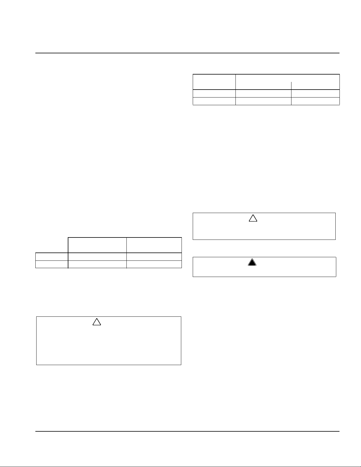
CLEANER AND SANITIZER
Manitowoc Ice Machine Cleaner and Sanitizer are
available in convenient 16 oz. (473 ml) and 1 gal (3.78 l)
bottles. These are the only cleaner and sanitizer
approved for use with these ice machines
Cleaner Part Number Sanitizer Part Number
16oz 94-0456-3 16oz 94-0565-3
1 Gallon 94-0580-3 1 Gallon 94-0581-3
These ice machines do not have a water curtain
covering the evaporator. The ice damper performs the
functions of the water curtain see Section 3 for details.
Do not damage the refrigeration circuit when
installing, maintaining or servicing the unit.
Do not use electrical appliances or accessories
other than those supplied by Manitowoc for your
ice machine model.
6 Part Number 040004686 8/15
Page 7
Section 2
!
Caution
!
Caution
!
Warning
Installation Instructions
Location of Ice Machine
The location selected for the ice machine must meet the
following criteria. If any of these criteria are not met,
select another location.
• The location must be indoors.
• The location must be free of airborne and other
contaminants.
• The air temperature must be at least 40F (4C), but
must not exceed 110F (43C).
• The location must not be near heat-generating
equipment or in direct sunlight.
• The location must be capable of supporting the
weight of the ice machine and a full bin of ice.
• The location must allow enough clearance for water,
drain and electrical connections in the rear of the ice
machine.
• The location must not obstruct airflow through or
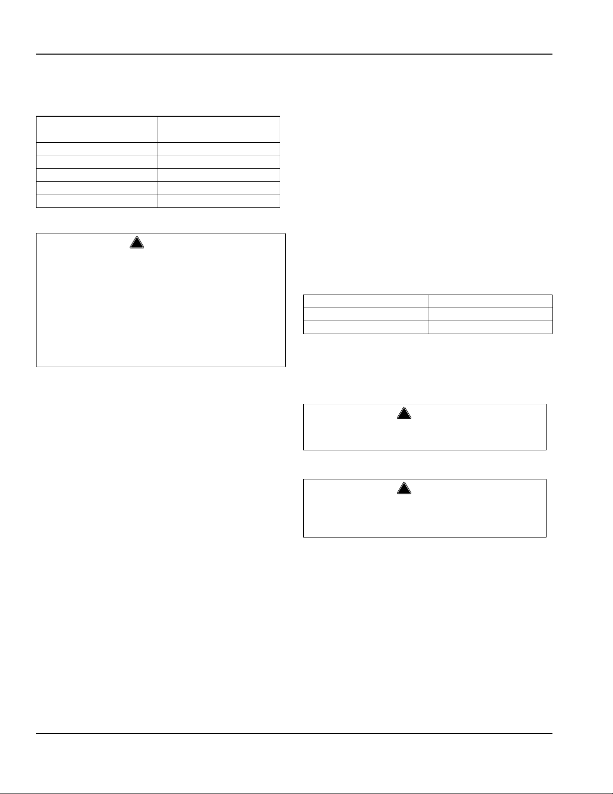
around the ice machine (condenser airflow is in and
out the front). Refer to the chart below for clearance
requirements.
Self-Contained
Air-Cooled
Top/Sides 5" (127 mm)* 5" (127 mm)*
Back 5" (127 mm)* 5" (127 mm)*
NOTE: The ice machine may be built into a cabin et .
There is no minimum clearance requirement for the top
or left and right sides of the ice machine. The listed
values are recommended for efficient operation and
servicing only.
The ice machine must be protected if it will be
subjected to temperatures below 32F (0C).
Failure caused by exposure to freezing
temperatures is not covered by the warranty. See
“Removal from Service/Winterization” Section 4.
Self-Contained
Water-Cooled
Ice Machine Heat of Rejection
Series
Ice Machine
K170 2200 2600
K270 3800 6000
* B.T.U./Hour
** Because the heat of rejection varies during the ice making cycle, the
figure shown is an average.
Ice machines, like other refrigeration equipment, reject
heat through the condenser. It is helpful to know the
amount of heat rejected by the ice machine when sizing
air conditioning equipment where self -c on tained air cooled ice machines are installed.
Air Conditioning** Peak
Heat of Rejection*
Leveling the Ice Machine
1. Screw the leveling legs onto the bottom of the ice
machine.
2. Screw the foot of each leg in as far as possible.
The legs must be screwed in tightly to prevent
them from bending.
3. Move the ice machine into its final position.
Do not obstruct ice machine vents or openings.
4. Level the ice machine to assure that the siphon
system functions correctly. Use a level on top of the
ice machine. Turn each foot as necessary to level
the ice machine from front to back and side to side.
NOTE: An optional 2 ½" caster assembly is available for
use in place of the legs on the K130, K170, K210 and
K270. Installation instructions are supplied with the
casters.
Part Number 040004686 8/15 7
Page 8
Installation Instructions Section 2
!
Warning
!
Warning
!
Warning
Electrical Service
GENERAL
All wiring must conform to local, state and national
codes.
VOLTAGE
The maximum allowable voltage variation is 10% of
the rated voltage on the ice machine model/serial
number plate at start-up (when the electrical load is
highest).
The 115/1/60 ice machines are factory pre-wired with a
8’ power cord, and NEMA 5-15P-plug configuration.
The 208-230/1/60 and 230/50/1 ice machines are
factory pre-wired with a 8’ power cord only, no plug is
supplied.
FUSE/CIRCUIT BREAKER
A separate fuse/circuit breaker must be provided for
each ice machine. Circuit breakers must be H.A.C.R.
rated (does not apply in Canada).
The ice machine must be grounded in accordance
with national and local electrical codes.
TOTAL CIRCUIT AMPACITY
The total circuit ampacity is used to help select the wire
size of the electrical supply.
The wire size (or gauge) is also dependent upon
location, materials used, length of run, etc., so it must be
determined by a qualified electrician.
GROUND FAULT CIRCUIT INTERRUPTER
Ground Fault Circuit Interrupter (GFCI/GFI) protection is
a system that shuts down the electric circuit (opens it)
when it senses an unexpected loss of power,
presumably to ground. Koolaire does not recommend
the use of a GFCI/GFI circuit protection with our
equipment. If code requires the use of a GFCI/GFI then
you must follow the local code. The circuit must be
dedicated, sized properly and there must be a panel
GFCI/GFI breaker. We do not recommend GFCI/GFI
outlets as they are known for more intermittent n uisance
trips than panel breakers.
PERSONAL INJURY POTENTIAL
If the supply cord is damaged, do not operate the
equipment until the cord is replaced by a service
agent or similarly qualified person.
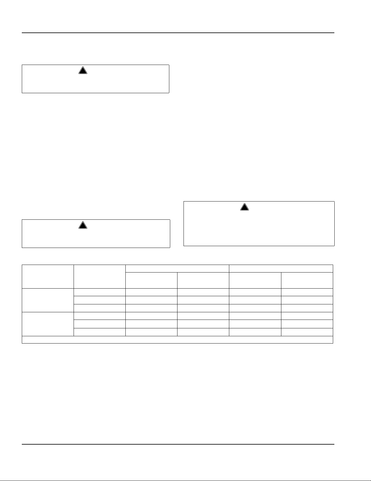
K130/K170/K210/K270 ICE MACHINE
Ice Machine Voltage
Phase
Cycle
K170 1 15/1/60 15 7.2 -- --
208-230/1/60 15 4.0* -- --
230/1/50 15 4.0* -- --
K270 1 15/1/60 15 10.7 15 9.9
208-230/1/60 15 5.2 15 4.7
230/1/50 15 5.2 15 4.7
* Indicates preliminary data
Air-Cooled Water Cooled
Maximum Fuse/
Circuit Breaker
Total Amps Maximum Fuse/
Circuit Breaker
Total Amps
8 Part Number 040004686 8/15
Page 9
Section 2 Installation Instructions
!
Warning
Important
Water Service/Drains
WATER SUPPLY
Local water conditions may require treatment of the
water to inhibit scale formation, filter sediment, remove
chlorine, and improve taste and clarity.
PERSONAL INJURY POTENTIAL
For ice making, connect to a potable water supply
only .
If you are installing a water filter system, refer to
the Installation Instructions supplied with the filter
system for ice making water inlet connections.
WATER INLET LINES
Follow these guidelines to install water inlet lines:
• Do not connect the ice machine to a hot water
supply. Be sure all hot water restrictors installed for
other equipment are working. (Check valves on sink
faucets, dishwashers, etc.)
• If water pressure exceeds the maximum
(80 psig-551.5 kPA) recommended pressure, obtain
a water pressure regulator from your local distributor.
• Install a water shut-off valve and union for both the
ice making and condenser water lines.
• Insulate water inlet lines to prevent condensation.
DRAIN CONNECTIONS
Follow these guidelines when installing drain lines to
prevent drain water from flowing back into the ice
machine and storage bin:
• Drain lines must have a 1.5 inch drop per 5 feet of
run (2.5 cm per meter), and must not create traps.
• The floor drain must be large enough to
accommodate drainage from all drains.
• Run separate bin and water-cooled condenser dra in
lines. Insulate them to prevent condensation.
• Vent the bin drai n to the atmosphere. Do not vent the
condenser drain on water-cooled models.
COOLING TOWER APPLICATIONS
(Water-Cooled Models)
A water cooling tower installation does not require
modification of the ice machine. The water regulator
valve for the condenser continues to control the
refrigeration discharge pressure.
It is necessary to know the amount of heat rejection and
the pressure drop through the condenser and water
valves (inlet and outlet) when using a cooling tower on
an ice machine.
• Water entering the condenser must not exceed 90F
(32C).
• Water flow through the con denser must not exceed 5
gallons (19 liters) per minute.
• Allow for a pressure drop of 7 psi (48 kPA) between
the condenser water inlet and the outlet of the ice
machine.
• Water exiting the condenser must not exceed 110F
(43C).
Water Supply and Drain Line Sizing/Connections
Location Water
Temperature
Ice Making
Water Inlet
Condenser W ater
Inlet
Condenser W ater
Drain
Bin Drain
Part Number 040004686 8/15 9
40F (4C) Min.
90F (32C) Max.
40F (4C) Min.
90F (32C) Max.
--- --- 1/2" Female Pipe
--- --- 1/2" Female Pipe
20 psi (137.9 kPA) Min.
80 psi (551.5 kPA) Max.
20 psi (137.9 kPA) Min.
150 psi (1034.2 kPA) Max.
Water
Pressure
Ice Machine
Fitting
3/8" Female Pipe
Thread
3/8" Female Pipe
Thread
K270 Only
1/2" Female Pipe
Thread
Thread
Thread
Tubing Size Up to Ice
Machine Fitting
3/8" (9.5 mm) minimum
inside diameter
3/8" (9.5 mm) minimum
inside diameter
K270 Only
1/2" (12.7 mm)
minimum inside diameter
1/2" (12.7 mm) minimum
inside diameter
1/2"” (12.7 mm) minimum
inside diameter
Page 10
Installation Instructions Section 2
!
Warning
Before Starting the Ice Machine
All ice machines are factory-operated and adjusted before shipment. Normally, new installations do not require any
adjustment.
To ensure proper operation, follow the Operational Checks in Section 3 of this manual. Starting the ice machine and
completing the Operational Checks are the responsibilities of the owner/operator.
Adjustments and maintenance procedures outlined in this manual are not covered by the warranty.
PERSONAL INJURY POTENTIAL
Do not operate equipment th at has been misused,
abused, neglected, damaged, or altered/modified
from that of original manufactured specifications.
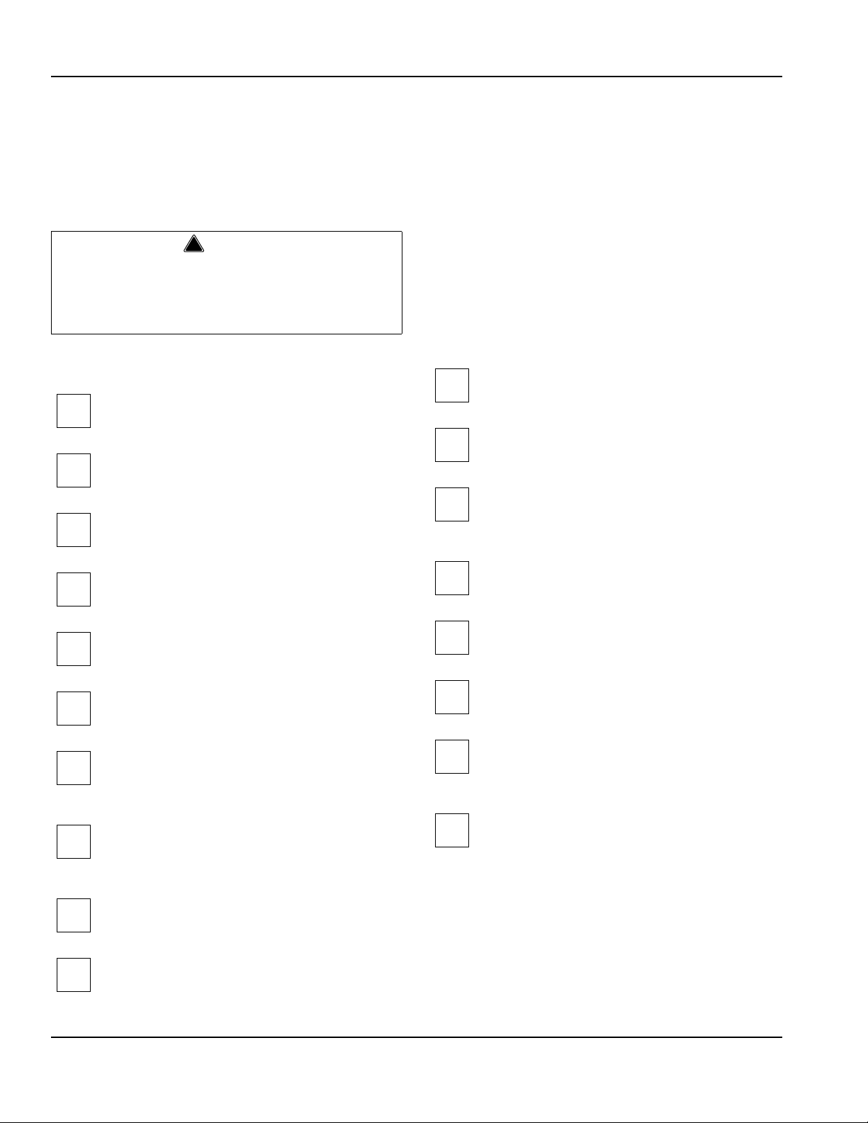
Installation Checklist
Are the ice machine and bin drains vented?
Is the ice machine level?
Are all electrical leads free from contact with
refrigeration lines and moving equipment?
Has all of the internal packing been removed?
Has the owner/operator been instructed
Have all of the electrical and water connection s
been made?
regarding maintenance and the us e of Cle an er
and Sanitizer?
Has the supply voltage been tested and
checked against the rating on the nameplate?
Is there proper clearance around the ice
machine for air circulation?
Is the ice machine grounded and polarity
correct?
Has the ice machine been installed where
ambient temperatures will remain in the range
of 40° – 110°F (4° – 43°C)?
Has the ice machine been installed where the
incoming water temperature will remain in the
range of 40° – 90°F (4° – 32°C)?
Is there a separate drain for the water-coole d
condenser?
Is there a separate drain for the bin?
Has the owner/operator completed the warranty
registration card?
Has the ice machine and bin been sanitized?
Is the toggle switch set to ice? (The toggle
switch is located directly behind the front panel).
Is the ice thickness control set correctly? (Refer
to Operational Checks to check/set the correct
ice bridge thickness).
Is the float valve in the OPEN position?
10 Part Number 040004686 8/15
Page 11

Section 3 Operation
Section 3
Operation
Ice Making Sequence of Operation
INITIAL START-UP OR START-UP AFTER AUTOMATIC SHUT-OFF
1. Pressure Equalization
Before the compressor starts the hot gas valve is
energized for 15 seconds to equalize pressures during
the initial refrigeration system start-up.
2. Refrigeration System Start-Up
The compressor starts after the 15-second pressure
equalization, and remains on throughout the entire
Freeze and Harvest Sequences. The hot gas valve
remains on for 5 seconds during initial compressor startup and then shuts off.
At the same time the compressor starts, the condenser
fan motor (air-cooled models) is supplied with power
throughout the entire Freeze and Harvest Sequences.
The fan motor is wired through a fan cycle pressure
control, therefore it may cycle on and off. (The
compressor and condenser fan motor are wired through
the relay . As a result, any time the relay coil is energized,
the compressor and fan motor are supplied with power.)
FREEZE SEQUENCE
3. Prechill
The compressor energizes to prechill the evaporator
prior to water flow.
4. Freeze
The water pump starts after the Prechill. An even flow of
water is directed across the evaporator and into each
cube cell, where it freezes.
When sufficient ice has formed, the water flow (not the
ice) contacts the ice thickness probe. After
approximately 7 seconds of continual water contact, the
Harvest Sequence is initiated. The ice machine cannot
initiate a Harvest Sequence until a 6-minute freeze time
has been surpassed.
HARVEST SEQUENCE
5. Harvest
The water pump de-energizes stopping flow over the
evaporator. The rising level of water in the sump trough
diverts water out of the overflow tube, purging excess
minerals from the sump trough. The hot gas valv e also
opens to divert hot refrigerant gas into the evaporator.
The refrigerant gas warms the evaporator causing the
cubes to slide, as a sheet, off the evaporator and into the
storage bin. The sliding sheet of cubes contacts the ice
damper, opening the bin switch.
The momentary opening and re-closing of the bin switch
terminates the Harvest Sequence and returns the ice
machine to the Freeze Sequence (steps 3 - 4).
AUTOMATIC SHUT-OFF
6. Automatic Shut-Off
When the storage bin is full at the end of a Harvest
Sequence, the sheet of cubes fails to clear the ice
damper and will hold it down. After the ice damper is
held open for 7 seconds, the ice machine shuts off. The
ice machine remains off for 3 minutes before it can
automatically restart.
The ice machine remains off until enough ice has been
removed from the storage bin to allow the ice to fall clear
of the damper. As the ice damper swings back to the
operating position, the bin switch re-closes and the ice
machine restarts (steps 1 - 2), provided the 3-minute
delay period is complete.
Part Number 040004686 8/15 11
Page 12
Operation Section 3
Energized Parts Chart
CONTROL BOARD RELAYS RELAY
INITIAL START-UP/
START UP AFTER
AUTO SHUT-OFF:
1. Pressure
Equalization
2. Refrigeration
System Start-up
FREEZE
SEQUENCE:
3. Pre-Chill
4. Freeze
HARVEST
SEQUENCE:
5. Harvest
1 2 3 3A 3B
WATER
PUMP
OFF ON OFF OFF OFF
OFF ON ON ON ON
OFF OFF ON ON ON
ON OFF ON ON ON
OFF ON ON ON ON
HOT GAS
VALVE
RELAY
COIL
COMPRESSOR CONDENSER
FAN MOTOR
LENGTH
of “ON”
TIME
15
Seconds
5
Seconds
30
Seconds
Until 7 sec.
water contact
with ice
thickness
probe
Bin switch
activation
AUTOMATIC SHUT-
OFF:
6. Auto Shut-Off
* Condenser Fan Motor: The fan motor is wired through a fan cycle pressure control, therefore, it may cycle on and off.
OFF OFF OFF OFF OFF
Until
bin switch
re-closes
12 Part Number 040004686 8/15
Page 13
Section 3 Operation
WATER
LEVEL
SIPHON
CAP
STANDPIPE
DRAIN
PRESS TO
OPEN
PRESS TO
CLOSE
Operational Checks
GENERAL
Your Koolaire ice machine was factory-operated and
adjusted before shipment. Normally , a newly installed ice
machine does not require any adjustment.
To ensure proper operation, always follow these
Operational Checks when starting the ice machine:
• for the first time
• after a prolonged out of service period
• after cleaning and sanitizing
Routine adjustments and maintenance procedures
outlined in this manual are not covered by the warranty.
SIPHON SYSTEM
To reduce mineral build-up and cleaning frequency, the
water in the sump trough must be purged during each
harvest cycle.
When the water pump de-energizes the level in the
water trough rises above the standpipe st artin g a siphon
action. The siphon action stops when the water level in
the sump trough drops. When the siphon action stops,
the float valve refills the water trough to the correct level.
Siphon System Check
Follow steps 1 through 6 under water level check.
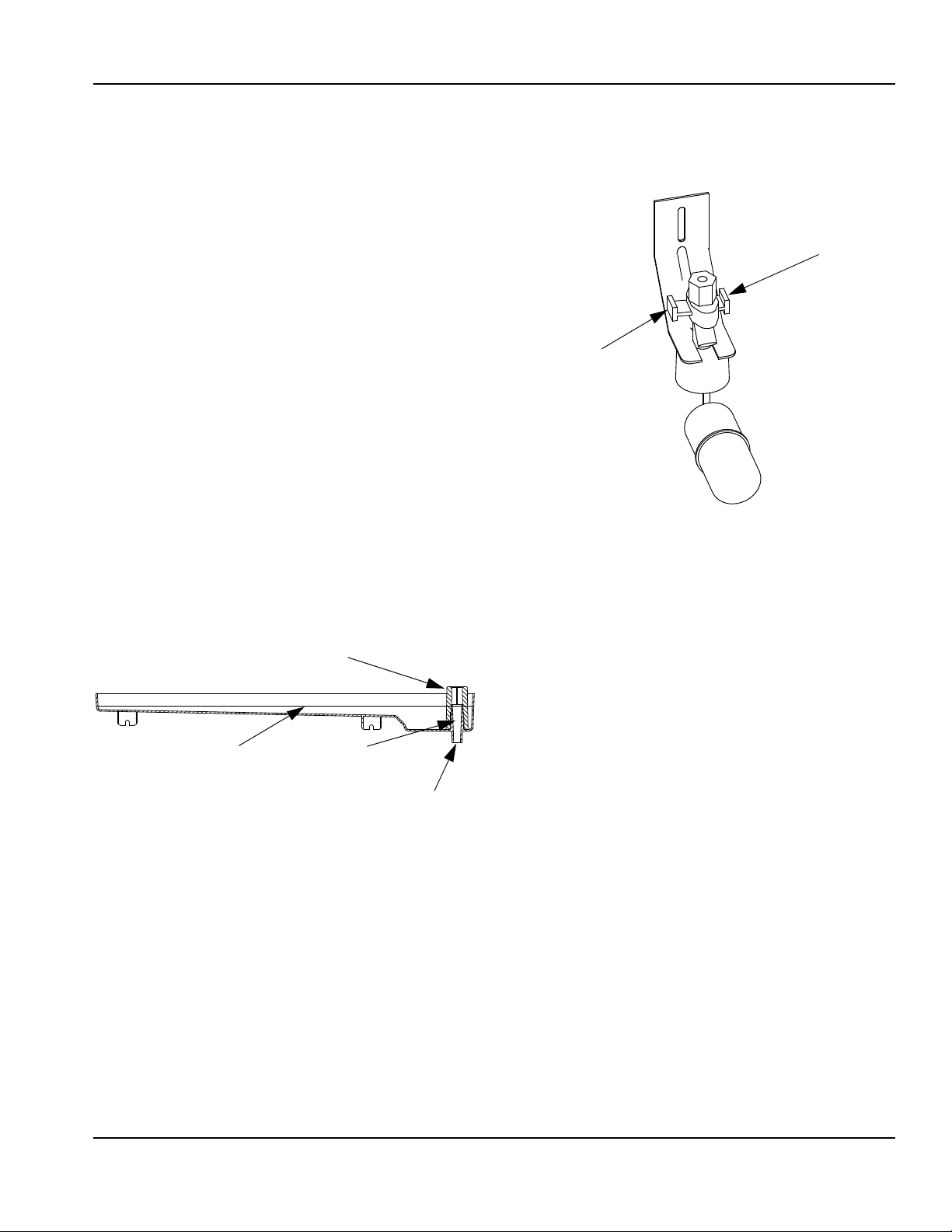
WATER FLOAT VALVE CHECK
Before water will flow into the water trough the float
valve shut-off must be in the OPEN position.
Water Level
Part Number 040004686 8/15 13
Page 14
Operation Section 3
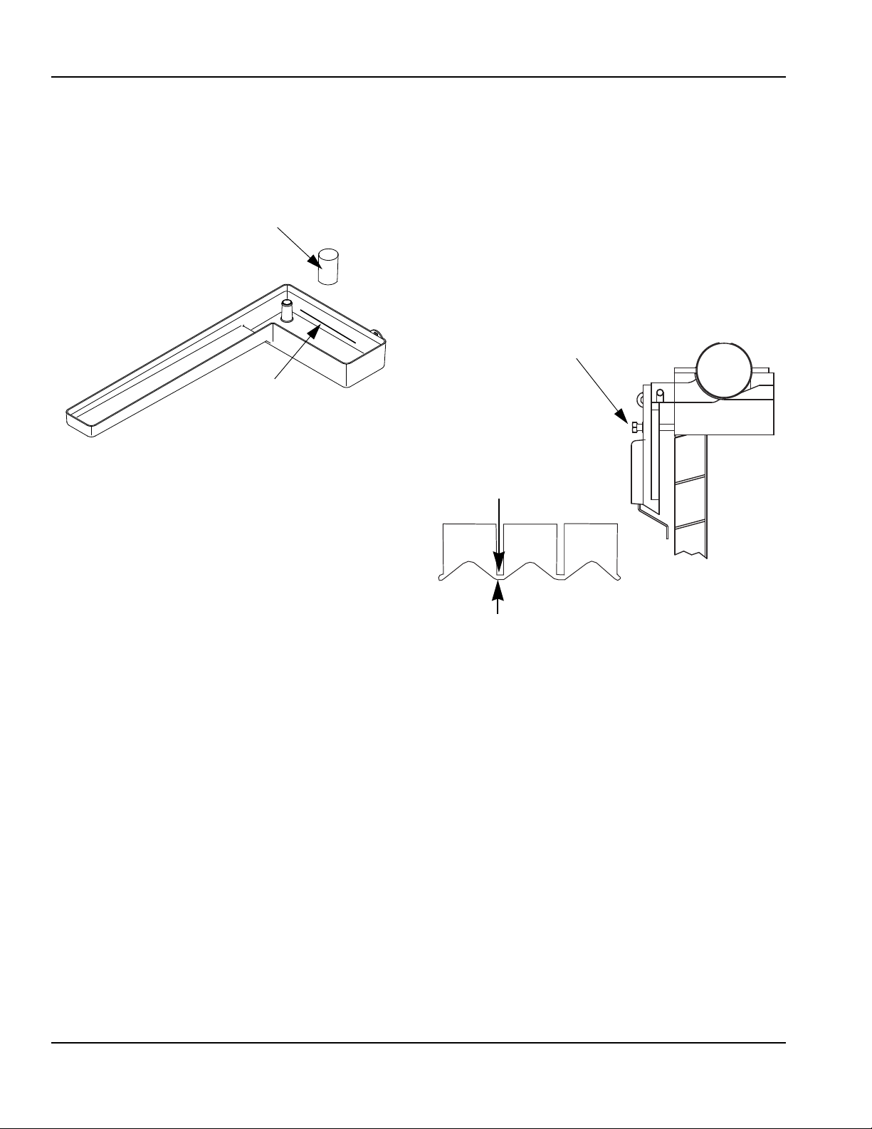
SIPHON CAP
SET THE WA TER LEVEL
TO THE LINE IN THE
WATER TROUGH
ADJUSTING SCREW
1/8" ICE BRIDGE THICKNESS
WATER LEVEL CHECK
Check the water level while the ice machine is in the ice
mode and the water pump is running. The correct water
level is 1/4" (6.3mm) to 3/8" (9.5mm) below the top of
the standpipe a line in the water trough indicates the
correct level.
Water Level
The float valve is factory-set for the proper water level. If
adjustments are necessary:
1. Verify the ice machine is level (see page 2-4).
2. Remove the siphon cap from the standpipe.
ICE BRIDGE THICKNESS CHECK
The ice thickness probe is factory-set to maintain the ice
bridge thickness at 1/8" (3.2 mm).
1. Inspect the bridge connecting the cubes. It should
be about 1/8" (3.2 mm) thick.
2. If adjustment is necessary, turn the ice thickness
probe adjustment screw clockwise to increase
bridge thickness, or counterclockwise to decrease
bridge thickness.
NOTE: Turning the adjustment 1/3 of a turn will change
the ice thickness about 1/16" (1.5 mm).
3. Place the ma in ON/OFF/WASH toggle switch to the
ON position, and wait until the float valve stops
adding water.
4. Adjust the water level to (1/4" to 3/8" (6.3 to 9.5 mm)
below the standpipe) the line in the water trough:
5. Loosen the two screws on the float valve bracket.
6. Raise or lower the float valve assembly as
necessary, then tighten the screws.
7. Move the main ON/OFF/ WASH toggle switch to the
OFF position. The water level in the trough will rise
above the standpipe and run down the drain.
8. Replace the siphon cap on the standpipe, and verify
water level and siphon action by repeating steps 3
through 5.
Ice Thickness Check
Make sure the ice thickness probe wire and the bracket
do not restrict movement of the probe.
14 Part Number 040004686 8/15
Page 15
Section 4 Maintenance
!
Caution
!
Caution
!
Warning
!
Caution
!
Warning
Section 4
Maintenance
Interior Cleaning and Sanitizing
GENERAL
Clean and sanitize the ice machine every six months for
efficient operation. If the ice machine requires more
frequent cleaning and sanitizing, consult a qualified
service company to test the water quality and
recommend appropriate water treatment.
The ice machine must be taken apart for cleaning and
sanitizing.
Use only Koolaire approved Ice Machine Cleaner
(part number 94-0546-3) and Sanitizer (part
number 94-0565-3). It is a violation of Federal law
to use these solutions in a manner inconsistent with
their labeling. Read and understand all labels
printed on bottles before use.
CLEANING AND SANITIZING PROCEDURE
Do not mix Ice Machine Cleaner and Sanitizer
solutions together. It is a violation of Federal law to
use these solutions in a manner inconsistent with
their labeling.
Ice machine cleaner is used to remove lime scale and
mineral deposits. Ice machine sanitizer disinfects and
removes algae and slime.
Step 1 Set the toggle switch to the OFF position after
ice falls from the evaporator at the end of a Harvest
cycle. Or, set the switch to the OFF position and allow
the ice to melt off the evaporator.
Never use anything to force ice from the evaporator.
Damage may result.
Step 2 Remove all ice from the bin.
Step 3 T o st art a cleaning cycle, move the toggle switch
to the WASH position.
Step 4 Add the proper amount of Ice Machine Cleaner
to the water trough.
Model Amount of Cleaner
K170 2 ounces (60 ml)
K270 2 ounces (60 ml)
Step 5 Wait until the clean cycle is complete
(approximately 22 minutes) then place the toggle switch
in the OFF position, disconnect power and water
supplies to the ice machine.
Wear rubber gloves and safety gogg les (an d/or face
shield) when handling Ice Machine Cleaner or
Sanitizer.
Part Number 040004686 8/15 15
Disconnect electric power to the ice machine at the
electric switch box before proceeding.
Page 16
Maintenance Section 4
DO NOT SOAK
WATER PUMP MOTOR IN
CLEANER OR SANITIZER
SOLUTIONS
When Used - REMOVE
THUMBSCREWS AND
WATER PUMP COVER
ICE THICKNESS
PROBE
COMPRESS SIDES OF ICE
THICKNESS PROBE
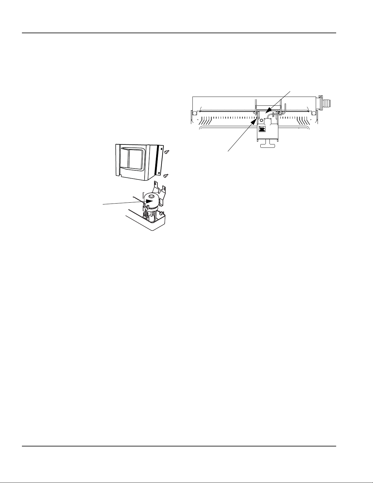
Step 6 Remove parts for cleaning.
A. Remove T wo Thumbscrews a nd W ater Pump
Cover (When Used).
B. Remove the Vinyl Hose Connecting the
Water Pump and Water Distribution Tube
C. Remove Water Pump
• Disconnect the water pump power cord
• Loosen the screws securing the pumpmounting bracket to the bulkhead
• Lift the pump and bracket assembly off the
mounting screws..
Water Pump Removal
D. Remove the Ice Thickness Probe
• Compress the side of the ice thickness probe
near the top hinge pin and remove it from the
bracket.
Ice Thickness Probe Removal
NOTE: At this point, the ice thickness probe can easily
be cleaned. If complete removal is desired follow the ice
thickness probe wire to the bulkhead grommet (exit
point) in the back wall. Pop the bulkhead grommet out of
the back wall by inserting fingernails or a flat object
between the back wall and the grommet and prying
forward. Pull the bulkhead grommet and wire forward
until the connector is accessible, then disconnect the
wire lead from the connector.
Ice Thickness Probe Cleaning
• Mix a solution of ice machine cleaner and water (2
ounces of cleaner to 16 ounces of water) in a
container.
• Soak the ice thickness probe a minimum of 10
minutes.
Clean all ice thickness probe surfaces and verify the ice
thickness probe cavity is clean. Rinse thoroughly with
clean water , then dry comple tely. Incomplete rinsing and
drying of the ice thickness probe can cause premature
harvest.
16 Part Number 040004686 8/15
Page 17

Section 4 Maintenance
!
Caution
1. LIFT UP
2. SLIDE BACK
3. SLIDE TO RIGHT
DISTRIBUTION
TUBE
THUMBSCREW
THUMBSCREW
LOCATING
PIN
3
2
1
INNER TUBE
TAB
KEYWAY
INNER TUBE
FLOAT VALVE
BRACKET
COMPRESSION
FITTING
CAP AND
FILTER SCREEN
SHUT-OFF VALVE
SPLASH SHIELD
FLOAT
E. Remove the Water Distribution Tube
K170/K210/K270 Water Distribution Tube Removal
• Loosen the two thumbscrews, which secure the
distribution tube.
• Lift the right side of the distribution tube up off the
locating pin, then slide it back and to the right.
F. Remove the Float Valve
• Turn the splash shield counterclockwise one or two
turns.
Do not force this removal. Be sure the locating pin is
clear of the hole before sliding the distribution tube
out.
Disassembly
• Twist both of the inner tube ends until the tabs line up
with the keyways.
• Pull the inner tube ends outward.
Water Distribution Tube Disassembly
Float Valve Removal
• Pull the float valve forward and off the mounting
bracket.
• Disconnect the water inlet tube from the float valve at
the compression fitting.
• Remove the cap and filter screen for cleaning.
Part Number 040004686 8/15 17
Page 18

Maintenance Section 4
REMOVE
SIPHON TUBE
UPPER
THUMBSCREW
LOWER
THUMBSCREWS
G. Remove the Water Trough
• Apply downward pressure on the siphon tube and
remove from the bottom of the water trough.
• Remove the upper thumbscrew.
• While supporting the water trough remove the two
thumbscrews from beneath the water trough.
• Remove the water trough from the bin area.
H. Remove the ice damper.
• Grasp ice damper and apply pressure toward th e lef t
hand mounting bracket.
• Apply pressure to the right hand mounting bracket
with thumb.
• Pull ice damper forward when the right hand ice
damper pin disengages.
Installation
• Place ice damper pin in left hand mounting bracket
and apply pressure toward the left hand mounting
bracket.
• Apply pressure to the right hand mounting bracket
with thumb.
• Push ice damper toward evaporator until right hand
damper pin engages.
18 Part Number 040004686 8/15
Page 19

Section 4 Maintenance
TRACK SLOT
SLIDE DOOR
FORWARD
STOP TAB
PRESS DOWN TO
RELEASE DOOR
ROLLER
I. Remove the Bin Door
• Grasp the rear of the bin door and pull bin door
forward approximately 5".
• Slide bin door to the rear while applying upward
pressure (The rear door pins will ride up into the track
slot and slide backward to the stop tab).
• While applying pressure against the bin door pull
down on the rear of each bin door track until the door
pins clear the stop tabs.
• Slide the rear door pins off the end and then below
the door track. Slide bin door forward allowing the
back of the door to lower into the bin. Continue
forward with the bin door until the front pins bottom
out in the track.
• Lift right side of door until the front pins clear the
track, then remove door from bin.
• Remove rollers (4) from all door pins.
Step 7 Mix a solution of cleaner and warm water .
Depending on the amount of mineral buildup, a larger
quantity of solution may be required. Use the ratio in the
table below to mix enough solution to thoroughly clean
all parts.
Solution Type Water Mixed with
Cleaner 1 gal. (4 l) 16 oz (500 ml) cleaner
Step 8 Use ½ of the cleaner/water solution to clean all
components. The cleaner solution will foam when it
contacts lime scale and mineral deposits; once the
foaming stops use a soft bristle brush, sponge or cloth
(not a wire brush) to carefully clean the parts. Soak the
parts for 5 minutes (15 – 20 minutes for heavily scaled
parts). Rinse all components with clean water.
Step 9 While components are soaking, use ½ of the
cleaner/water solution to clean all foodzone surfaces of
the ice machine and bin. Use a nylon brush or cloth to
thoroughly clean the following ice machine areas:
• Evaporator plastic parts – including top, bottom and
sides
• Bin bottom, sides and top
Rinse all areas thoroughly with clean water.
Step 10 Mix a solution of sanitizer and warm water.
Solution Type Water Mixed With
Sanitizer 6 gal. (23 l) 4 oz (120 ml) sanitizer
Part Number 040004686 8/15 19
Page 20

Maintenance Section 4
!
Warning
Step 11 Use 1/2 of the sa nit izer /wa te r so lut ion to
sanitize all removed components. Use a cloth or sponge
to liberally apply the solution to all surfaces of the
removed parts or soak the removed parts in the
sanitizer/water solution. Do not rinse parts after
sanitizing.
Step 12 Use 1/2 of the sanitizer/water solution to
sanitize all foodzone surfaces of the ice machine and
bin. Use a cloth or sponge to liberally apply th e solu tion.
When sanitizing, pay particular attention to the following
areas:
• Evaporator plastic parts - including top, bottom and
sides
• Bin bottom, sides and top
Do not rinse the sanitized areas.
Step 13 Replace all removed components.
Step 14 Reapply power and water t o the ice machine
and place the toggle switch in the WASH position.
Step 15 Add the proper amount of Ice Machine
Sanitizer to the water trough.
Model Amount of Sanitizer
K170 2.2 ounces (66 ml)
K270 1.9 ounces (57 ml)
Step 16 Wait until the sanitize cycle is complete
(approximately 22 minutes) then place the toggle switch
in the OFF position, disconnect power and water
supplies to the ice machine.
Disconnect electric power to the ice machine at the
electric switch box before proceeding.
Step 17 Repeat step 6 to remove parts for hand
sanitizing.
Step 18 Mix a solution of sanitizer and warm water.
Solution Type Water Mixed With
Sanitizer 6 gal. (23 l) 4 oz (120 ml) sanitizer
Step 19 Use 1/2 of the sanitizer/water solution to
sanitize all removed components. Use a cloth or sponge
to liberally apply the solution to all surfaces of the
removed parts or soak the removed parts in the
sanitizer/water solution. Do not rinse parts after
sanitizing.
Step 20 Use 1/2 of the sanitizer/water solution to
sanitize all foodzone surfaces of the ice machine and
bin. Use a cloth or sponge to liberally apply the solution.
When sanitizing, pay particular attention to the following
areas:
• Evaporator plastic parts - including top, bottom and
sides
• Bin bottom, sides and top
Do not rinse the sanitized areas.
Step 21 Replace all removed components.
Step 22 Reapply power and water to the ice machine
and place the toggle switch in the ICE position.
20 Part Number 040004686 8/15
Page 21

Section 4 Maintenance
!
Warning
!
Warning
Ice Machine Inspection
Check all water fittings and lines for leaks. Also, make
sure the refrigeration tubing is not rubbing or vibrating
against other tubing, panels, etc.
Do not put anything (boxes, etc.) in front of the ice
machine. There must be adequate airflow through and
around the ice machine to maximize ice productio n an d
ensure long component life.
Exterior Cleaning
Clean the area around the ice machine as often as
necessary to maintain cleanliness and efficient
operation.
Sponge any dust and dirt off the outside of the ice
machine with mild soap and water. Wipe dry with a
clean, soft cloth.
A commercial grade stainless steel cleaner/polish can
be used as necessary.
Cleaning the Condenser
GENERAL
Disconnect electric power to the ice machine head
section and the remote condensing unit at the
electric service switches before cleaning the
condenser.
A dirty condenser restricts airflow, resulting in
excessively high operating temperatures. This reduces
ice production and shortens component life.
• Clean the condenser at least every six months.
The condenser fins are sharp. Use care when
cleaning them.
• Shine a flashlight through the condenser to check for
dirt between the fins.
• Blow compressed air or rinse with water from the
inside out (opposite direction of airflow).
• If dirt still remains call a service agent to clean the
condenser.
Removal from Service/Winterization
1. Clean and san itiz e th e ice ma ch in e.
2. Move the ICE/OFF/CLEAN switch to OFF.
3. Turn off the water supply, disconnect and drain the
incoming ice-making water line at the rear of the ice
machine and drain the water trough.
4. Energize the ice machine, wait one minute for the
water inlet valve to open and blow compressed air in
both the incoming water and the drain openings in
the rear of the ice machine to remove all water.
5. Move ICE/OFF/CLEAN switch to OFF and
disconnect the electric power at the circuit breaker
or the electric service switch.
6. Fill spray bottle with sanitizer and spray all interior
food zone surfaces. Do not rinse and allow to air d ry.
7. Replace all panels.
Part Number 040004686 8/15 21
Page 22

Maintenance Section 4
THIS PAGE INTENTIONALLY LEFT BLANK
22 Part Number 040004686 8/15
Page 23

Section 5
Customer Support
Checklist
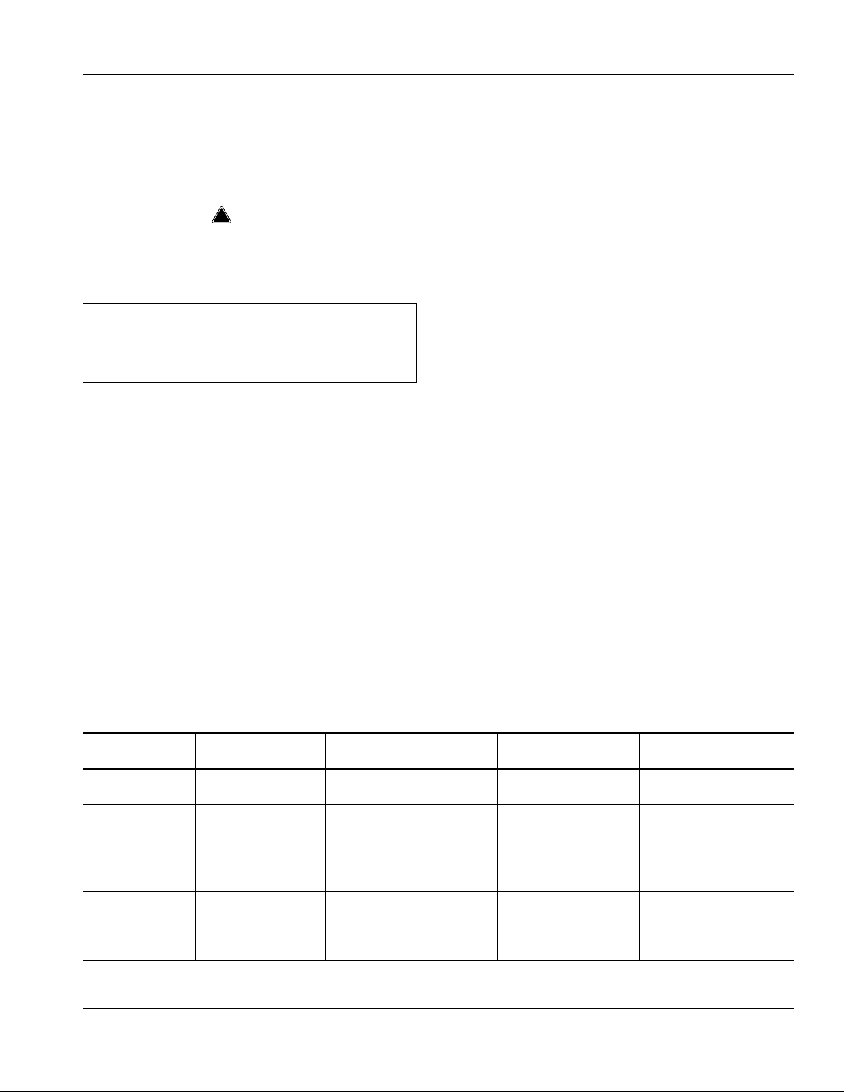
If a problem arises during operation of your ice machine, follow the checklist below before calling service. Routine
adjustments and maintenance procedures are not covered by the warranty.
Problem Possible Cause To Correct
Ice machine does not operate. No electrical power to the ice machine. Replace the fuse/reset the breaker/turn on
the main switch/plug power cord into
receptacle.
ON/OFF/WASH toggle switch set improperly. Move the toggle switch to the ON position.
Damper in open position (down). Damper must be in upright position and
capable of swinging freely.
Ice machine stops, and can be
restarted by moving the toggle
switch to OFF and back to ON.
Ice machine does not release ice or
is slow to harvest.
Ice machine does not cycle into
harvest mode.
Ice quality is poor
(soft or not clear).
Safety limit feature stopping the ice machi ne. Refer to “Safety Limit Feature” on the next
page.
Ice machine is dirty. Clean and sanitize the ice machine.
Ice machine is not level. Level the ice machine.
Low air temperature around ice machine
(air-cooled models).
Water regulating valve leaks in harvest
mode (water-cooled models).
The six-minute freeze time lock-in has not
expired yet.
Ice thickness probe is dirty. Clean and sanitize the ice machine.
Ice thickness probe wire is disconnected. Connect the wire.
Ice thickness probe is out of adjustment. Adjust the ice thickness probe.
Uneven ice fill (thin at top of evaporator). See “Shallow or Incomplete Cubes” on the
Poor incoming water quality. Contact a qualified service company to
Water filtration is poor. Replace the filter.
Ice machine is dirty. Clean and sanitize the ice machine.
Water siphon is not working. Check the water siphon system.
Water softener is working improperly
(if applicable).
Air temperature must be at least 40F
(4C).
Replace water regulating valve.
Wait for freeze lock-in to expire.
next page.
test the quality of the incoming water and
make appropriate filter recommendations.
Repair the water softener.
Continued on next page...
Part Number 040004686 8/15 23
Page 24

Customer Support Section 5
Problem Possible Cause To Correct
Ice machine produces shallow or
incomplete cubes, or the ice
fill pattern on the evaporator is
incomplete.
Low ice capacity. Water float valve filter screen is dirty. Remove and clean the filter screen.
Ice thickness probe is out of adjustment. Adjust the ice thickness probe.
Water trough level is to high or too low. Check the water level.
Water float valve filter screen is dirty. Remove and clean the filter screen.
Water filtration is poor. Replace the filter.
Hot incoming water. Connect the ice machine to a cold water
supply.
Water float valve is not working. Remove the water float valve and clean it.
Incorrect incoming water pressure. Water pressure must be 20-80 psi (137.9 -
551.5 kPA).
Ice machine is not level. Level the ice machine.
Incoming water supply is shut off. Open the water service valve.
Water float valve stuck open or leaking. Remove the water float valve and clean it.
The condenser is dirty. Clean the condenser.
High air temperature around ice machine
(air-cooled models).
Inadequate clearance around the ice
machine.
Objects stacked around ice machine,
blocking airflow to condenser
(air-cooled models).
Air temperature must not exceed 110F
(43C).
Provide adequate clearance.
Remove items blocking airflow.
Safety Limit Feature
In addition to the standard safety controls, such as the
high pressure cutout, your Koolaire ice machine feature s
built-in safety limits which will stop the ice machine if
conditions arise which could cause a major component
failure.
Before calling for service, re-start the ice machine using
the following procedure:
1. Move the ON/OFF/WASH switch to OFF and then
back to ON.
A. If the safety limit feature has stopped the ice
machine, it will restart after a short delay.
Proceed to step 2.
B. If the ice machine does not restart, see “Ice
machine does not operate” on the previous
page.
2. Allow the ice machine to run to determine if the
condition is recurring.
A. If the ice machine stops again, the condition has
recurred. Call for service.
B. If the ice machine continues to run, the condition
has corrected itself. Allow the ice machine to
continue running.
24 Part Number 040004686 8/15
Page 25

Section 5 Customer Support
Commercial Ice Machine Warranty
The Koolaire brand warranty is administered through
Manitowoc Ice (hereinafter referred to as the “COMPANY”)
warrants for a period of thirty six (36) months from the
installation date (except as limited below) that new ice
machines manufactured by the COMPANY shall be free of
defects in material or workmanship under normal and
proper use and maintenance as specified by the COMPANY
and upon proper installation and start-up in accordance
with the instruction manual supplied with the ice machine.
The COMPANY’s warranty hereunder with respect to the
compressor shall apply for an additional twenty-four
months, excluding all labor charges, and with respect to the
evaporator for an additional twenty-four months, including
labor charges.
The obligation of the COMPANY under this warranty is
limited to the repair or replacement of parts, components,
or assemblies that in the opinion of the COMPANY are
defective. This warranty is further limited to the cost of
parts, components or assemblies and standard straight time
labor charges at the servicing location.
Time and hourly rate schedules, as published from time to
time by the COMPANY, apply to all service procedures.
Additional expenses including without limitation, travel
time, overtime premium, material cost, accessing or removal
of the ice machine, or shipping are the responsibility of the
owner, along with all maintenance, adjustments, cleaning,
and ice purchases. Labor covered under this warranty must
be performed by a COMPANY Contracted Service
Representative or a refrigeration service agency as qualified
and authorized by the COMPANY’s local Distributor. The
COMPANY’s liability under this warranty shall in no event be
greater than the actual purchase price paid by customer for
the ice machine.
The foregoing warranty shall not apply to (1) any part or
assembly that has been altered, modified, or changed; (2)
any part or assembly that has been subjected to misuse,
abuse, neglect, or accidents; (3) any ice machine that has
been installed and/or maintained inconsistent with the
technical instructions provided by the COMPANY; or (4) any
ice machine initially installed more than five years from the
serial number production date. This warranty shall not apply
if the Ice Machine’s refrigeration system is modified with a
condenser, heat reclaim device, or parts and assemblies
other than those manufactured by the COMPANY, unless the
COMPANY approves these modifications for specific
locations in writing.
THIS WARRANTY IS IN LIEU OF ALL OTHER WARRANTIES
OR GUARANTEES OF ANY KIND, EXPRESSED OR IMPLIED,
INCLUDING ANY IMPLIED WARRANTY OF
MERCHANTABILITY OR FITNESS FOR A PARTICULAR
PURPOSE. In no event shall the COMPANY be liable for any
special, indirect, incidental or consequential damages. Upon
the expiration of the warranty period, the Company's
liability under this warranty shall terminate. The foregoing
warranty shall constitute the sole liability of the COMPANY
and the exclusive remedy of the customer or user.
To secure prompt and continuing warranty service, the
warranty registration card must be completed and sent to
the COMPANY within five (5) days from the installation date.
Complete the following and retain for your record:
Distributor/Dealer __________________________________
Model Number Serial Number ________________________
Installation Date ___________________________________
Manitowoc Foodservice-Ice Machine Division
2110 South 26th Street, P.O. Box 1720
Manitowoc, WI 54221-1720
Telephone: 920-682-0161
Fax: 920-683-7585Website:www.kool-aire.com
Part Number 040004686 8/15 25
Page 26

Customer Support Section 5
Residential Ice Machine Limited Warranty
WHAT DOES THIS LIMITED WARRANTY COVER?
Subject to the exclusions and limitations below, Manitowoc
Foodservice (“Manitowoc”) warrants to the original
consumer that any new ice machine manufactured by
Manitowoc (the “Product”) shall be free of defects in
material or workmanship for the warranty period outlined
below under normal use and maintenance, and upon
proper installation and start-up in accordance with the
instruction manual supplied with the Product.
HOW LONG DOES THIS LIMITED WARRANTY LAST?
Product Covered Warranty Period
Ice Machine Twelve (12) months
from the sale date
WHO IS COVERED BY THIS LIMITED WARRANTY?
This limited warranty only applies to the original consumer
of the Product and is not transferable.
WHAT ARE MANITOWOC ICE’S OBLIGATIONS UNDER
THIS LIMITED WARRANTY?
If a defect arises and Manitowoc receives a valid warranty
claim prior to the expiration of the warranty period,
Manitowoc shall, at its option: (1) repair the Product at
Manitowoc’s cost, including standard straight time labor
charges, (2) replace the Product with one that is new or at
least as functionally equivalent as the original, or (3) refund
the purchase price for the Product. Replacement parts are
warranted for 90 days or the balance of the original
warranty period, whichever is longer. The foregoing
constitutes Manitowoc’s sole obligation and the
consumer’s exclusive remedy for any breach of this limited
warranty. Manitowoc’s liability under this limited warranty
is limited to the purchase price of Product. Additional
expenses including, without limitation, service travel time,
overtime or premium labor charges, accessing or removing
the Product, or shipping are the responsibility of the
consumer.
HOW TO OBTAIN WARRANTY SERVICE
To obtain warranty service or information regarding your
Koolaire product, please contact:
MANITOWOC ICE
2110 So. 26th St.
P.O. Box 1720,
Manitowoc, WI 54221-1720
Telephone: 920-682-0161 Fax: 920-683-7585
www.kool-aire.com
WHAT IS NOT COVERED?
This limited warranty does not cover, and you are solely
responsible for the costs of: (1) periodic or routine
maintenance, (2) repair or replacement of the Product or
parts due to normal wear and tear, (3) defects or damage to
the Product or parts resulting from misuse, abuse, neglect,
or accidents, (4) defects or damage to the Product or parts
resulting from improper or unauthorized alterations,
modifications, or changes; and (5) defects or damage to any
Product that has not been installed and/or maintained in
accordance with the instruction manual or technical
instructions provided by Manitowoc. To the extent that
warranty exclusions are not permitted under some state
laws, these exclusions may not apply to you.
EXCEPT AS STATED IN THE FOLLOWING SENTENCE, THIS LIMITED
W
ARRANTY IS THE SOLE AND EXCLUSIVE WARRANTY OF MANITOWOC
W
ITH REGARD TO THE PRODUCT. ALL IMPLIED WARRANTIES ARE
S
TRICTLY LIMITED TO THE DURATION OF THE LIMITED WARRANTY
A
PPLICABLE TO THE PRODUCTS AS STATED ABOVE, INCLUDING BUT
N
OT LIMITED TO, ANY WARRANTY OF MERCHANTABILITY OR OF
F
ITNESS FOR A PARTICULAR PURPOSE.
Some states do not allow limitations on how long an
implied warranty lasts, so the above limitation may not
apply to you.
IN NO EVENT SHALL MANITOWOC OR ANY OF ITS AFFILIATES BE
L
IABLE TO THE CONSUMER OR ANY OTHER PERSON FOR ANY
I
NCIDENTAL, CONSEQUENTIAL OR SPECIAL DAMAGES OF ANY KIND
(I
NCLUDING, WITHOUT LIMITATION, LOSS PROFITS, REVENUE OR
B
USINESS) ARISING FROM OR IN ANY MANNER CONNECTED WITH THE
P
RODUCT, ANY BREACH OF THIS LIMITED WARRANTY, OR ANY OTHER
C
AUSE WHATSOEVER, WHETHER BASED ON CONTRACT, TORT OR ANY
O
THER THEORY OF LIABILITY.
Some states do not allow the exclusion or limitation of
incidental or consequential damages, so the above
limitation or exclusion may not apply to you.
HOW STATE LAW APPLIES
This limited warranty gives you specific legal rights, and you
may also have rights that vary from state to state or from
one jurisdiction to another.
REGISTRATION CARD
To secure prompt and continuing warranty service, this
warranty registration card must be completed and sent to
Manitowoc within thirty (30) days from the sale date.
Complete the following registration card and send it to
Manitowoc.
26 Part Number 040004686 8/15
Page 27

Section 1
Généralités
Références des modèles . . . . . . . . . . . . . . . . . . . . . . . . . . . . . . . . . . . . . . . . . . . . . 27
Accessoires . . . . . . . . . . . . . . . . . . . . . . . . . . . . . . . . . . . . . . . . . . . . . . . . . . . . . . . 27
Section 2
Instructions d’installation
Emplacement de la machine à glaçons . . . . . . . . . . . . . . . . . . . . . . . . . . . . . . . . . 28
Machine à glaçons Chaleur de rejection . . . . . . . . . . . . . . . . . . . . . . . . . . . . . . . . 28
Niveler la machine à glaçons . . . . . . . . . . . . . . . . . . . . . . . . . . . . . . . . . . . . . . . . . 28
Alimentation électrique . . . . . . . . . . . . . . . . . . . . . . . . . . . . . . . . . . . . . . . . . . . . . . 29
Service d’eau/Évacuations d’eau . . . . . . . . . . . . . . . . . . . . . . . . . . . . . . . . . . . . . . 30
Dimensionnement/Raccordement des conduites d’alimentation en eau et d’évacu-
ation . . . . . . . . . . . . . . . . . . . . . . . . . . . . . . . . . . . . . . . . . . . . . . . . . . . . . . . . . . . . . 31
Avant la mise en marche de la machine à glaçons . . . . . . . . . . . . . . . . . . . . . . . 32
Liste de vérification d’installation . . . . . . . . . . . . . . . . . . . . . . . . . . . . . . . . . . . . . 32
Table des matières
Roulettes de bac . . . . . . . . . . . . . . . . . . . . . . . . . . . . . . . . . . . . . . . . . . . . . . . . 27
Système de filtration d’eau Arctic Pure . . . . . . . . . . . . . . . . . . . . . . . . . . . . . . . 27
Nettoyant et désinfectant Manitowoc . . . . . . . . . . . . . . . . . . . . . . . . . . . . . . . . 27
Généralités . . . . . . . . . . . . . . . . . . . . . . . . . . . . . . . . . . . . . . . . . . . . . . . . . . . . 29
Tension . . . . . . . . . . . . . . . . . . . . . . . . . . . . . . . . . . . . . . . . . . . . . . . . . . . . . . . 29
Fusible/Disjoncteur . . . . . . . . . . . . . . . . . . . . . . . . . . . . . . . . . . . . . . . . . . . . . . 29
Courant admissible de circuit total . . . . . . . . . . . . . . . . . . . . . . . . . . . . . . . . . . 29
Différentiel . . . . . . . . . . . . . . . . . . . . . . . . . . . . . . . . . . . . . . . . . . . . . . . . . . . . . 29
Machine à glaçons K130/K170/K210/K270 . . . . . . . . . . . . . . . . . . . . . . . . . . . 29
Alimentation en eau . . . . . . . . . . . . . . . . . . . . . . . . . . . . . . . . . . . . . . . . . . . . . 30
Lignes d’arrivée d’eau . . . . . . . . . . . . . . . . . . . . . . . . . . . . . . . . . . . . . . . . . . . . 30
Raccordements d’évacuation . . . . . . . . . . . . . . . . . . . . . . . . . . . . . . . . . . . . . . 30
Applications avec tour de refroidissement . . . . . . . . . . . . . . . . . . . . . . . . . . . . 30
Section 3
Fonctionnement
Séquence de fabrication des glaçons . . . . . . . . . . . . . . . . . . . . . . . . . . . . . . . . . . 33
Mise en marche initiale ou mise en marche après arrêt automatique . . . . . . . 33
Séquence de congélation . . . . . . . . . . . . . . . . . . . . . . . . . . . . . . . . . . . . . . . . . 33
Séquence de démoulage . . . . . . . . . . . . . . . . . . . . . . . . . . . . . . . . . . . . . . . . . 33
Arrêt automatique . . . . . . . . . . . . . . . . . . . . . . . . . . . . . . . . . . . . . . . . . . . . . . . 33
Tableau de pièces sous tension . . . . . . . . . . . . . . . . . . . . . . . . . . . . . . . . . . . . . . . 34
Vérifications opérationnelles . . . . . . . . . . . . . . . . . . . . . . . . . . . . . . . . . . . . . . . . . 35
Généralités . . . . . . . . . . . . . . . . . . . . . . . . . . . . . . . . . . . . . . . . . . . . . . . . . . . . 35
Système de siphonnement . . . . . . . . . . . . . . . . . . . . . . . . . . . . . . . . . . . . . . . . 35
Contrôle du robinet à flotteur d’eau . . . . . . . . . . . . . . . . . . . . . . . . . . . . . . . . . . 35
Contrôle du niveau d’eau . . . . . . . . . . . . . . . . . . . . . . . . . . . . . . . . . . . . . . . . . 36
Contrôle de l’épaisseur du pont de glace . . . . . . . . . . . . . . . . . . . . . . . . . . . . . 36
Part Number 040004686 8/15 26
Page 28

Section 4
Entretien
Section 5
Service clientèle
Table of Contents (continued)
Nettoyage et désinfection intérieurs . . . . . . . . . . . . . . . . . . . . . . . . . . . . . . . . . . . . 37
Généralités . . . . . . . . . . . . . . . . . . . . . . . . . . . . . . . . . . . . . . . . . . . . . . . . . . . . 37
Procédure de nettoyage et de désinfection . . . . . . . . . . . . . . . . . . . . . . . . . . . . 37
Inspection de la machine à glaçons . . . . . . . . . . . . . . . . . . . . . . . . . . . . . . . . . . . . 43
Nettoyage extérieur . . . . . . . . . . . . . . . . . . . . . . . . . . . . . . . . . . . . . . . . . . . . . . . . . 43
Nettoyage du condenseur . . . . . . . . . . . . . . . . . . . . . . . . . . . . . . . . . . . . . . . . . . . . 43
Généralités . . . . . . . . . . . . . . . . . . . . . . . . . . . . . . . . . . . . . . . . . . . . . . . . . . . . 43
Mise hors service/Hivérisation . . . . . . . . . . . . . . . . . . . . . . . . . . . . . . . . . . . . . . . . 43
Liste de vérification . . . . . . . . . . . . . . . . . . . . . . . . . . . . . . . . . . . . . . . . . . . . . . . . . 44
Fonction de limite de sécurité . . . . . . . . . . . . . . . . . . . . . . . . . . . . . . . . . . . . . . . . . 45
Garantie commerciale de la machine à glaçons . . . . . . . . . . . . . . . . . . . . . . . . . . 46
Garantie limitée résidentielle de la machine à glaçons . . . . . . . . . . . . . . . . . . . . 47
27
Page 29

Section 1
!
Avertissement
!
Avertissement
! Avertissement
! Avertissement
Généralités
Références des modèles
Le présent manuel s’applique aux modèles suivants :
Autonomes refroidis
à l’air
KD0172A -KY0174A -KR0270A KR0271W
KD0272A KD0273W
KY0274A KY0275W
RISQUE DE BLESSURES CORPORELLES
Le présent appareil ne doit pas être utilisé par des
personnes (enfants y compris) ayant des capacités
physiques, sensorielles ou mentales diminuées, ou
ayant un manque d’expérience et de connaissance,
à moins que celles-ci n’aient reçu une formation sur
l’utilisation de l’appareil par une personne
responsable de leur sécurité.
Quelques-unes hz modèles Mai le contrat en haut à
150 gramme de R290 ( la proposition refrigerant. R290
( la proposition ) c'est inflammable dans concentrations
de aérer entre à peu près 2.1% pour 9.5% de volume
LEL inférieur explosion limiter et UEL supérieur
explosion limiter ). Une ignition source à une
température supérieur que 470°C c'est eu besoin de
pour une combustion à se rencontrer. Se reporter à
nameplate à identifier l'espèce de refrigerant dans
votre équipement. Unique qualifié et qualifiée
personnel informé de les dangers êtes permis à
travailler one l'équipements.
Autonomes refroidis
à l’eau
Accessoires
Contacter le distributeur pour obtenir ces accessoires en
option :
ROULETTES DE BAC
Remplace les pieds standard.
SYSTÈME DE FILTRATION D’EAU ARCTIC PURE
Conçus spécifiquement pour les machines à glaçons,
les filtres à eau Arctic Pure sont une méthode efficace,
fiable et abordable pour empêcher la formation de tartre,
filtrer les sédiments et éliminer le goût et l’odeur du
chlore.
NETTOYANT ET DÉSINFECTANT
Le nettoyant et le désinfectant pour machines à glaçons
sont disponibles en bouteilles pratiques de 16 oz. (473
ml) et 1 gallon (3,78 l). Ce nettoyant et ce désinfectant
sont les seuls produits approuvés pour les machines.
Référence du nettoyant Référence du désinfectant
16 oz 94-0456-3 16 oz 94-0565-3
1 Gallon 94-0580-3 1 Gallon 94-0581-3
Les machines à glaçons modèles comportent pas de
rideau d’eau couvrant l’évaporateur. L’amortisseur de
glaçons effectue les fonctions du rideau d’eau, voir la
Section 3 pour de plus amples détails.
Font pas tort les réfrigération circuit quand installer ,
maintien ou révision l'unité.
Font pas utilité électrique appareils ou
accessoires à part là pourvoyeur près de
Koolaire pour votre glace usiner travailler
comme mannequin.
Part Number 040004686 8/15 28
Page 30

Section 2
!
Attention
!
Attention
!
Avertissement
Instructions d’installation
Emplacement de la machine à glaçons
Le choix de l’emplacement pour la machine à glaçons
doit respecter les critères suivants. Si l’un de ces critères
n’est pas respecté, choisir un autre emplacement.
• L’emplacement doit se trouver à l’intérieur.
• L’emplacem ent doit être exempt d’agents aé roportés
et de toute autre substance contaminante.
• La température de l’air doit être au moins de 4 C (40
F), mais ne doit pas excéder 43 C (110 F).
• L’emplacement ne doit pas se trouver à proximité
d’appareils générateurs de chaleur ou à la lumière
directe du soleil.
• L’emplacement doit pouvoir supporter le poids de la
machine à glaçons et un bac plein de glaçons.
• L’emplacement doit prévoir suffisamment de
dégagement pour les prises d’eau, raccordements
de vidange et raccordements électriques à l’arrière
de la machine à glaçons.
• L’emplacement ne doit pas obstruer l’écoulement
d’air dans la machine ou autour de celle-ci (le débit
d’air du condenseur entre et sort sur le devant).
Consulter le tableau ci-dessous pour obtenir les
conditions d’espace requises.
Autonome
Refroidie à l’air
Haut/Côtés 127 mm (5 po)* 127 mm (5 po)*
Arrière 127 mm (5 po)* 127 mm (5 po)*
Autonome refroidie
à l’eau
Machine à glaçons Chaleur de rejection
Séries
Machine à
glaçons
K170 2200 2600
K210 2400 3400
* B.T.U./Heure
** Étant donné que la chaleur de rejection varie pendant le cycle de
fabrication de glaçons, les chiffres représentés sont une moyenne.
Les machines à glaçons, tout comme tout autre
équipement de réfrigération, rejet ten t la ch ale ur par le
condenseur. Il est utile de connaître la quantité de
chaleur rejetée par la machine à glaçons lors du
dimensionnement du matériel de conditionnement d’air
où sont installées les machines à glaçons autonomes
refroidies par l’air.
Chaleur de rejection*
Climatisation** Crête
Niveler la machine à glaçons
1. Visser les pattes de nivellement sur le dessous de la
machine à glaçons.
2. Visser le pied de chaque patte aussi loin que
possible.
Les pattes doivent être bien serrées pour les
empêcher de se courber.
3. Déplacer la machine à glaçons dans sa position
définitive.
REMARQUE : La machine à glaçons peut être
encastrée dans une armoire.
Il n’y aucune exigence de dégagement minimum pour le
haut ou la gauche et la droite de la machine à glaçons.
Les valeurs indiquées sont recommandées uniquement
pour un fonctionnement et un entretien efficaces.
La machine à glaçons doit être protégée si elle est
susceptible d’être soumise à des températures
inférieures à 0 C (32 F). Toute défaillance due à
une exposition à des températures inférieures à
0
°C n’est pas couverte par la garantie. Voir « Mise
hors service/Hivérisation » Section 4.
Font pas obstruer glace usiner orifice ou poste
vacant.
4. Niveler la machine à glaçons de manière que le
système de siphonnement fonctionne correctement.
Utiliser un niveau sur le dessus de la machine à
glaçons. Tourner chaque pied selon les besoins
pour niveler la machine à glaçons d’avant en arrière
et latéralement.
REMARQUE : Un ensemble de roulette de 2-1/2 po en
option est disponible pour remplacer les pieds sur les
modèles K130, K170, K210 et K270. Les instructions
d’installation sont fournies avec les roulettes.
29 Part Number 040004686 8/15
Page 31

Section 2 Instructions d’installation
! Avertissement
! Avertissement
! Avertissement
Alimentation électrique
GÉNÉRALITÉS
Tout le câblage doit être conforme aux codes
locaux, régionaux et nationaux.
TENSION
La variation de tension admissible maximale est de
10 % de la tension nominale sur la plaque de
référence/numéro de série de la machine à glaçons
(lorsque la charge électrique est la plus haute).
Les machines à glaçons 115/1/60 sont précâblées en
usine avec un cordon d’alimentation de 2,4 m (8 pi) et
une configuration de fiche NEMA 5-15P.
Les machines à glaçons 208-230/1/60 et 230/50/1 sont
précâblées en usine avec un cordon d’alimentation de
2,4 m (8 pi) uniquement, aucune fiche n’est fournie.
FUSIBLE/DISJONCTEUR
Un fusible/disjoncteur séparé doit être fourni pour
chaque machine à glaçons. Les disjoncteurs doivent
être de catégorie H.A.C.R. (ne s’applique pas au
Canada).
COURANT ADMISSIBLE DE CIRCUIT TOTAL
Le courant admissible de circuit total permet de
sélectionner la dimension de câble de l’alimentation
électrique.
La dimension de câble (ou le calibre) dépendant
également de l’emplacement, des matériaux utilisés, de
la longueur de la conduite, etc., celle-ci doit être
déterminée par un électricien qualifié.
DIFFÉRENTIEL
Une protection par différentiel (GFCI/GFI) est un
système qui coupe le circuit électrique (l’ouvre) quand il
détecte une perte inattendue de courant, probablement
à la terre. Koolaire ne recommande pas l’emploi d’une
protection de circuit GFCI/GFI avec notre équipement.
Si le code requiert l’emploi d’un GFCI/GFI, il convient
alors de respecter le code local. Le circuit doit être
spécialisé, de dimensions correctes et il doit y avoir un
disjoncteur de panneau GFCI/GFI. Nous ne
recommandons l’emploi de prises GFCI/GFI étant donné
qu’elles sont connues pour provoquer davantage de
défaillances parasites intermittentes que les disjoncteurs
de panneau.
La machine à glaçons doit être mise à la terre
conformément aux codes de l’électricité nationaux
et locaux.
MACHINE À GLAÇONS K130/K170/K210/K270
Machine à
glaçons
K170 115/1/60 15 7,2 -- --
K270 115/1/60 15 10,7 15 9,9
Tension/Phase/
Cycle
208-230/1/60 15 4,0* -- --
230/1/50 15 4,0* -- --
208-230/1/60 15 5,2 15 4,7
230/1/50 15 5,2 15 4,7
Fusible/
Disjoncteur
maximum
RISQUE DE BLESSURES CORPORELLES
Si le cordon d’alimentation est endommagé, ne pas
faire fonctionner l’équipement avant d’avoir le
cordon remplacé par un agent de service ou une
personne possédant les mêmes qualifications.
Refroidie à l’air Refroidie à l’eau
Intensité totale Fusible/
Disjoncteur
maximum
Intensité totale
Part Number 040004686 8/15 30
Page 32

Instructions d’installation Section 2
!
Avertissement
Important
Important
Service d’eau/Évacuations d’eau
ALIMENTATION EN EAU
En fonction des conditions d’eau locales, il peut s’avérer
nécessaire de traiter l’eau pour empêcher la formation
de tartre, filtrer les sédiments, éliminer le chlore et
améliorer le goût et la clarté.
RISQUE DE BLESSURES CORPORELLES
Pour fabriquer des glaçons, connecter à une
alimentation en eau potable uniquement.
Pour installer un système de filtration d’eau,
consulter les Instructions d’installation fournies
avec le système de filtration pour les
raccordements d’arrivée d’eau de fabrication des
glaçons.
LIGNES D’ARRIVÉE D’EAU
Suivre ces directives pour l’installation des lignes
d’arrivée d’eau :
• Ne pas raccorder la machine à glaçons à une
alimentation en eau chaude. Sassurer que tous les
restricteurs d’eau chaude installés pour les autres
appareils f
robinets d’éviers, lave-vaisselle, etc.).
• Si la pression de l’eau dépasse la pression maximale
recommandée (80 psig-551,5 kPa), se procurer un
régulateur de pression d’eau auprès d’un
distributeur.
• Installer un robinet d’arrêt de l’eau et un raccord pour
les lignes d’eau de fabrication de glaçons et d’eau du
condenseur.
• Isoler les lignes d’arrivée d’eau pour éviter les
problèmes de condensation.
onctionnent (clapets de non-retour sur
RACCORDEMENTS D’ÉVACUATION
Suivre ces directives lors de l’installation des conduites
d’évacuation pour empêcher l’eau de retourner s’écouler
dans la machine à glaçons et dans le bac de stockage :
• Les lignes d’évacuation doivent avoir une inclinaison
de 2,5 cm par mètre (1,5 pouce/5 pieds) et ne
doivent pas créer de siphons.
• Le siphon de sol doit être suffisamment grand pour
recevoir l’eau provenant de toutes les évacuations.
• Faire fonctionner séparément les lignes d’évacuation
du bac et du condenseur refroidi à l’eau. Les isoler
pour prévenir la condensation.
• Ventiler l’évacuation du bac dans l’atmosphère. Ne
pas ventiler l’évacuation du condenseur sur les
modèles refroidis par eau.
APPLICATIONS AVEC TOUR DE REFROIDISSEMENT
(Modèles refroidis par eau)
Une installation avec tour de refroidissement à eau ne
requiert pas de modification de la machine à glaçons. Le
régulateur d’eau du condenseur continue de contrô ler la
pression de refoulement de réfrigération.
Il est nécessaire de connaître la quantité de chaleur
rejetée ainsi que la chute de pression dans le
condenseur et les robinets d’eau (entrée et sortie) lors
de l’utilisation d’une tour de refroidissement sur une
machine à glaçons.
• L’eau entra nt dans le condenseur ne doit pas
excéder 32 C (90 F).
• La quantité d’eau traversant le condenseur ne doit
pas dépasser 19 litres (5 gallons) par minute.
• Prévoir une chute de pression de 48 kPa (7 psi) entr e
l’arrivée d’eau du condenseur et la sortie de la
machine à glaçons.
• L’eau sortant du condenseur ne doit pas excéder
43
C (110 F).
L’État du Massachusetts exige que tous les
modèles refroidis par eau soient raccordés
uniquement à un système de tour de
refroidissement à boucle fermée.
31 Part Number 040004686 8/15
Page 33

Section 2 Instructions d’installation
!
Attention
Dimensionnement/Raccordement des conduites d’alimentation en eau et d’évacuation
La tuyauterie doit être conforme au x codes locaux
et régionaux.
Emplacement T empérature
de l’eau
Arrivée d’eau pour
la fabrication
de glaçons
Arrivée d’eau de
condenseur
Évacuation d’eau
du condenseur
Évacuation de bac — — Filetage femelle de
4 C (40 F) Min.
32 C (90 F) Max.
4 C (40 F) Min.
32 C (90 F) Max.
— — Filetage femelle de
Pression d’eau Raccordement de la
machine à glaçons
137,9 kPA (20 psi) Min.
551,5 kPA (80 psi) Max.
137,9 kPA (20 psi) Min.
1034,2 kPA (150 psi) Max.
Filetage femelle de
tuyau de 3/8 po
Filetage femelle de
tuyau de 3/8 po
K270 uniquement
Filetage femelle de
tuyau de 1/2 po
tuyau de 1/2 po
tuyau de 1/2 po
Dimension de tubulure
jusqu’à raccordement de
machine à glaçons
9,5 mm (3/8 po) diamètre
intérieur minimum
9,5 mm (3/8 po) diamètre
intérieur minimum
K270 uniquement
12,7 mm (1/2 po) diamètre
intérieur minimum
12,7 mm (1/2 po) diamètre
intérieur minimum
12,7 mm (1/2 po) diamètre
intérieur minimum
Part Number 040004686 8/15 32
Page 34

Instructions d’installation Section 2
! Avertissement
Avant la mise en marche de la machine à glaçons
Toutes les machines à glaçons Koolaire sont mises en route et ajustées en usine avant l’expédition. Normalement,
les nouvelles installations ne requièrent aucun ajustement.
Pour garantir un bon fonctionnement, suivre les Contrôles opérationnels figurant à la Section 3 du présent manuel. La
mise en marche de la machine à glaçons et exécuter les contrôles opérationnels sont la responsabilité du
propriétaire/de l’opérateur.
Les réglages et les procédures de maintenance indiqués dans ce manuel ne sont pas couverts p ar la
garantie.
RISQUE DE BLESSURES CORPORELLES
Ne pas utiliser un équipement qui aura été mal utilisé,
abusé, négligé, endommagé ou dont les
spécifications originales de fabrication auront été
altérées/modifiées.
Liste de vérification d’installation
Y a-t-il une évacuation séparée pour le bac ?
La machine est-elle à niveau ?
Tout l’emballage interne a-t-il été retiré ?
Tous les raccordements électriques et d’eau
ont-ils été effectués ?
La tension d’alimentation a-t-elle été testée et
vérifiée par rapport à la valeur nominale
indiquée sur la plaque signalétique ?
Y a-t-il un espace approprié autour de la
machine à glaçons pour la circulation d’air ?
La machine à glaçons est-elle mise à la terre et
la polarité est-elle correcte ?
La machine à glaçons a-t-elle été installée là où
des températures ambiantes resteront dans la
fourchette de 4 à 43 °C (40 à 110 °F) ?
La machine à glaçons a-t-elle été installée là où
la température d’eau entrante restera dans la
fourchette de 4 à 32 °C (40 à 90 °F) ?
Les évacuations de machine à glaçons et de
bac sont-elles aérées ?
Tous les fils électriques sont-ils exempts de
contact des lignes de réfrigération et de
l’équipement mobile ?
Le propriétaire/l’opérateur ont-ils été informés
de l’entretien et de l’utilisation du nettoyant et
du désinfectant Manitowoc ?
Le propriétaire/l’opérateur a-t-il rempli la carte
de garantie ?
La machine à glaçons et le bac ont-ils été
désinfectés ?
L’interrupteur à bascule est-il réglé sur ICE ?
(L’interrupteur à bascule se trouve directement
derrière le panneau avant.)
La commande d’épaisseur de glaçons est-elle
réglée correctement ? (Consulter les Contrôles
opérationnels pour vérifier/établir l’épaisseur de
pont de glace correcte.)
Y a-t-il une évacuation séparée pour le
condenseur refroidi par eau ?
Le robinet à flotteur est-il en position OPEN
[OUVERTE] ?
33 Part Number 040004686 8/15
Page 35

Section 3
Fonctionnement
Séquence de fabrication des glaçons
MISE EN MARCHE INITIALE OU MISE EN MARCHE APRÈS ARRÊT AUTOMATIQUE
1. Équilibrage de pression
Avant le démarrage du compresseur, le robinet de gaz
chaud est sous tension pendant 15 secondes pour
équilibrer les pressions pendant la mise en marche
initiale du système de réfrigération.
2. Mise en marche du système de réfrigération
Le compresseur démarre après l’équilibrage de pression
de 15 secondes et reste en marche pendant toutes les
séquences de congélation et de démoulage. Le robinet
de gaz chaud reste sous tension pendant 5 secondes
pendant la mise en marche initiale du compresseur , puis
se ferme.
Au moment du démarrage du compresseur , le moteur du
ventilateur de condenseur (modèles refroidis à l’air) est
mis sous tension pendant toutes les séquences de
congélation et de démoulage. Le moteur du ventilateur
étant par une commande par pression de cycle de
ventilateur, il peut par conséquent, effectuer des
révolutions en alternance. (Le compresseur et le moteur
du ventilateur de condenseur sont câblés par le relais.
En conséquence, à chaque fois que la bobine de relais
est sous tension, le compresseur et le moteur de
ventilateur sont alimentés.)
SÉQUENCE DE CONGÉLATION
3. Prérefroidissement
Le compresseur est sous tension pendant avant
l’écoulement d’eau pour prérefroidir l’évaporateur.
4. Congélation
La pompe à eau démarre après le prérefroidissement de
30 secondes. Un écoulement uniforme d’eau est dirigé
sur l’évaporateur et dans chaque cellule de glaçon où
elle se congèle.
Lorsque suffisamment de glaçons se sont formés,
l’écoulement d’eau (pas les glaçons) entre en contact
avec la sonde d’épaisseur de glace. Au bout de 7
secondes environ de contact continu avec l’eau, la
séquence démoulage est initiée. La machine à glaçons
ne peut initier une séquence de démoulage qu’après
avoir excédé un temps de congélation de 6 minutes.
SÉQUENCE DE DÉMOULAGE
5. Démoulage
La pompe à eau est mise hors tension et stoppe
l’écoulement sur l’évaporateur. Le niveau montant de
l’eau dans le bac de puisard détourne l’eau en la faisant
sortir du tube de trop-plein, en purgeant tous les
minéraux excessifs du bac de puisard. Le robinet de gaz
chaud s’ouvre également pour détourner le gaz
frigorigène chaud dans l’évaporateur.
Le gaz frigorigène chauffe l’évaporateur entraînant le
glissement des cubes, comme une feuille, de
l’évaporateur et dans le bac de stockage. La feuille
glissante de cubes entre en contact avec l’amortisseur
de glaçons, en ouvrant le commutateur de bac.
L’ouverture et la fermeture instantanées du
commutateur de bac termine la séquence de démoulage
et remet la machine à glaçons en séquence de
congélation (étapes 3 - 4).
ARRÊT AUTOMATIQUE
6. Arrêt automatique
Lorsque le bac de stockage est plein à la fin d’une
séquence de démoulage, la feuille de glaçons ne se
dégage pas de l’amortisseur de glaçons et le
maintiendra enfoncé. Une fois que l’amortisseur de
glaçons est maintenu ouvert pendant 7 secondes, la
machine à glaçons s’arrête. La machine reste arrêtée
pendant 3 minutes avant qu’elle puisse redémarrer
automatiquement.
La machine à glaçons reste arrêtée jusqu’à ce que
suffisamment de glaçons aient été retirés du bac de
stockage pour permettre aux glaçons de tomber à l’écar t
de l’amortisseur . Au fur et à mesure que l’amortisseur d e
glaçons bascule en position de fonctionnement, le
commutateur de bac se referme et la machine à glaçons
se remet en marche (étapes 1 - 2), à condition que le
délai de 3 minutes soit terminé.
Part Number 040004686 8/15 34
Page 36

Fonctionnement Section 3
Tableau de pièces sous tension
RELAIS DE TABLEAU DE COMMANDE RELAIS
1 2 3 3A 3B
MISE EN MARCHE
INITIALE/MISE EN
MARCHE APRÈS
ARRÊT
AUTOMATIQUE :
1. Équilibrage de
pression
2. Mise en marche
du système de
réfrigération
SÉQUENCE DE
CONGÉLA TION :
3.
Prérefroidissement
4. Congélation
SÉQUENCE DE
DÉMOULAGE :
5. Démoulage
POMPE À
EAU
OFF/
ARRÊT
OFF/
ARRÊT
OFF/
ARRÊT
ON/
MARCHE
OFF/
ARRÊT
ROBINET
DE GAZ
CHAUD
ON/
MARCHE
ON/
MARCHE
OFF/
ARRÊT
OFF/
ARRÊT
ON/
MARCHE
BOBINE DE
RELAIS
OFF/ARRÊT OFF/ARRÊT OFF/ARRÊT 15 Secondes
ON/
MARCHE
ON/
MARCHE
ON/
MARCHE
ON/
MARCHE
COMPRESSEUR MOTEUR DU
VENTILATEUR DE
CONDENSEUR
ON/MARCHE ON/MARCHE 5 Secondes
ON/MARCHE ON/MARCHE 30 Secondes
ON/MARCHE ON/MARCHE
ON/MARCHE ON/MARCHE
DURÉE DE
TEMPS
« ON »
(MARCHE)
Jusqu’à 7
sec. de
contact d’eau
avec la sonde
d’épaisseur
de glace
Activation de
commutateur
de bac
ARRÊT
AUTOMATIQUE :
6. Arrêt
automatique
* Moteur de ventilateur de condenseur : Le moteur du ventilateur étant câblé par une commande par pression de cycle de ventilateur, il peut par
conséquent, effectuer des révolutions en alternance.
OFF/
ARRÊT
OFF/
ARRÊT
OFF/ARRÊT OFF/ARRÊT OFF/ARRÊT
Jusqu’à
refermeture
du
commutateur
de bac
35 Part Number 040004686 8/15
Page 37

Section 3 Fonctionnement
NIVEAU
D’EAU
TÊTE DE
SIPHON
TUYAU
D’ALIMENTATION
VERTICAL
ÉVACUATION
APPUYER
POUR
OUVRIR
APPUYER
POUR
FERMER
Vérifications opérationnelles
GÉNÉRALITÉS
Cette machine à glaçons Koolaire a été mise en route et
ajustée en usine avant l’expédition. Normalement, une
machine à glaçons nouvellement installée ne requiert
pas d’être ajustée.
Pour garantir un bon fonctionnement, toujours suivre les
contrôles opérationnels avant de mettre la machine à
glaçons en marche :
• pour la première fois
• après une période prolongée hors service
• après le nettoyage et la désinfection
Les réglages de routine et les procédures de
maintenance périodique indiqués dans ce manuel ne
sont pas couverts par la garantie.
SYSTÈME DE SIPHONNEMENT
Pour réduire les dépôts de minéraux et la fréquence du
nettoyage, l’eau dans le bac de puisard doit être purgée
pendant chaque cycle de démoulage.
Lorsque la pompe à eau est hors tension, le niveau da ns
le bac à eau monte au-dessus du tuyau d’alimentation
vertical démarrant ainsi une action de siphon. L’action
de siphon s’arrête lorsque le niveau d’eau dans le bac
de puisard baisse. Lorsque l’action de siphon s’arrête, le
robinet à flotteur remplit le bac à eau au niveau correct.
Contrôle du système de siphonnement
Suivre les étapes 1 à 6 sous la section Contrôle du
niveau d’eau.
CONTRÔLE DU ROBINET À FLOTTEUR D’EAU
Avant que l’eau ne s’écoule dans le bac à eau, l’arrêt du
robinet à flotteur doit être en position OPEN
(OUVERTE).
Niveau d’eau
Part Number 040004686 8/15 36
Page 38

Fonctionnement Section 3
TÊTE DE SIPHON
FIXER LE NIVEAU
D’EAU AU TRAIT DANS
LE BAC À EAU
VIS DE RÉGLAGE
ÉPAISSEUR DE PONT DE
GLACE DE 1/8 po
CONTRÔLE DU NIVEAU D’EAU
Contrôler le niveau d’eau pendant que la machine à
glaçons se trouve en mode ICE et que la pompe à eau
fonctionne. Le niveau d’eau correct se trouve entre
6,3 mm (1/4 po) et 9,5 mm (3/8 po) sous le haut du
tuyau d’alimentation vertical. Un trait dans le bac à eau
indique le niveau correct.
Niveau d’eau
Le robinet à flotteur est réglé en usine pour le niveau
d’eau approprié. Si des réglages s’avèrent nécessaires :
1. Vérifier que la machine à glaçons est à niveau (voir
page 2-4).
2. Retirer la tête de siphon du tuyau d’alimentation
vertical.
CONTRÔLE DE L’ÉPAISSEUR DU PONT DE GLACE
La sonde d’épaisseur des glaçons est réglée en usine
pour maintenir l’épaisseur du pont de glace à 3,2 mm
(1/8 po).
1. Inspecter le pont connectant les glaçons. Son
épaisseur doit être d’environ 3,2 mm (1/8 po).
2. Si un réglage est nécessaire, tourner la vis de
réglage de la sonde d’épaisseur des glaçons da ns le
sens des aiguilles d’une montre pour augmenter
l’épaisseur du pont ou dans le sens contraire des
aiguilles d’une montre pour diminuer l’épaisseur du
pont.
REMARQUE : Si la vis de réglage est tournée de 1/3,
l’épaisseur des glaçons changera d’environ 1,5 mm
(1/16 po).
3. Mettre le commutateur à bascule principal ON/OFF/
WASH en position ON et attendre jusqu’à ce que le
robinet à flotteur arrête d’ajouter de l’eau.
4. Ajuster le niveau d’eau (6,3 à 9,5 mm [1/4 po à
3/8 po] sous le tuyau d’alimentation vertical) au trait
dans le bac à eau :
5. Desserrer les deux vis sur le support de robinet à
flotteur.
6. Remonter ou abaisser l’ensemble de robinet à
flotteur selon les besoins, puis resserrer les vis.
7. Mettre le commutateur à bascule principal ON/OFF/
WASH en position OFF. Le niveau d’eau dans le bac
remontera au-dessus du tuyau d’alimentation
vertical et s’écoulera dans l’évacuation.
8. Remettre la tête de siphon sur le tuyau
d’alimentation vertical et vérifier le niveau d’eau et
l’action de siphon en répétant les étapes 3 à 5.
Contrôle de l’épaisseur des glaçons
Veiller à ce que le fil de la sonde d’épaisseur des
glaçons et le support n’entravent pas le mouvement de
la sonde.
37 Part Number 040004686 8/15
Page 39

Nettoyage et désinfection intérieurs
!
Attention
!
Attention
!
Avertissement
!
Attention
! Avertissement
Section 4
Entretien
GÉNÉRALITÉS
Nettoyer et désinfecter la machine à glaçons tous les six
mois pour un fonctionnement efficace. Si la machine à
glaçons requiert un nettoyage et une désinfection plus
fréquents, contacter une entreprise de maintenance
qualifiée pour tester la qualité de l’eau et recommander
un traitement approprié de l’eau.
La machine à glaçons doit être démontée pour le
nettoyage et la désinfection.
Utiliser uniquement le nettoyant (référence
94-0546-3) et le désinfectant (référence 94-0565-3)
pour machine à glaçons approuvés par Manitowoc.
Utiliser ces solutions sans tenir compte des
instructions figurant sur les étiquettes est une
violation de la loi fédérale. Lire et comprendre
toutes les étiquettes imprimées sur les flacons
avant utilisation.
PROCÉDURE DE NETTOYAGE ET DE DÉSINFECTION
Ne jamais utiliser quoi que ce soit pour forcer la
glace à sortit de l’évaporateur et ce, pour éviter tout
dommage.
Étape 2 Retirer tous les glaçons du bac.
Étape 3 Pour démarrer un cycle de nettoyage, mettre
le commutateur à bascule en position WASH.
Étape 4 Ajouter la quantité appropriée du nettoyant
pour machines à glaçons au bac d’eau.
Modèle Quantité de nettoyant
K170 60 ml (2 onces)
K270 60 ml (2 onces)
Étape 5 Attendre la fin du cycle de nettoyage
(22
minutes environ) puis placer le commutateur à
bascule en position OFF, mettre hors tension et couper
les alimentations en eau à la machine à glaçons.
Couper l’alimentation de la machine à glaçons au
niveau de la boîte de distribution électrique avant de
continuer.
Ne pas mélanger les solutions nettoyantes et
désinfectantes ensemble pour machines à glaçons.
Utiliser ces solutions sans tenir compte des
instructions figurant sur les étiquettes est une
violation de la loi fédérale.
Porter des gants en caoutchouc et des lunettes de
sécurité (et/ou un masque) lors de la m anipulation
du nettoyant ou du désinfectant pour machine à
glaçons.
Utiliser le nettoyant pour machine à glaçons pour
éliminer le tartre et les dépôts minéraux. Le désinfect ant
pour machine à glaçons désinfecte et élimine les a lgues
et tout film biologique.
Étape 1 Régler l’interrupteur à bascule sur la position
OFF une fois que les glaçons tombent de l’évaporateur
à la fin d’un cycle de récupération des glaçons. Ou
mettre l’interrupteur en position OFF et laisser fondre la
glace hors de l’évaporateur.
Étape 6 Retirer les pièces à nettoyer.
A. Supprimer Deux Thumbscrews et L'eau
Pomper Parcourir ( quand Utilisée ).
B. Retirer le tuyau en vinyle
• Débrancher le tuyau d’eau du tube de distribu tion et
de la pompe à eau
Part Number 040004686 8/15 38
Page 40

Entretien Section 4
Quand Utilisée
SUPPRIMER
THUMBSCREWS
ET L'EAU POMPER
PARCOURIR
NE PAS FAIRE
TREMPER LE
MOTEUR DE LA
POMPE À EAU
DANS LA
SOLUTION
NETTOYANTE OU
DÉSINFECTANTE
SONDE D’ÉPAISSEUR
DE GLAÇONS
COMPRIMER LES CÔTÉS DE LA
SONDE D’ÉPAISSEUR DE GLAÇONS
!
Attention
1. RELEVER
2. FAIRE GLISSER VERS L’ARRIÈRE
3. FAIRE GLISSER VERS LA DROITE
TUBE DE
DISTRIBUTION
VIS PAPILLON
VIS PAPILLON
GOUPILLE
DE
MONTAGE
3
2
1
C. Retirer la pompe à eau
• Débrancher le cordon d’alimentation de la
pompe à eau.
Retrait de pompe à eau
• Desserrer les vis maintenant le support de
fixation de pompe à la cloison.
• Soulever la pompe et l’ensemble de support
des vis de fixation.
D. Retrait de la sonde d’épaisseur de glaçons
• Comprim er le côté de la sonde d’épa isseur de
glaçons près de l’axe d’articulation supérieur
et retirer du support.
Nettoyage de la sonde d’épaisseur de glaçons
• Mélanger une solution de nettoyant pour machines à
glaçons et d’eau (60 ml [2 onces] de nettoyant pour
500 ml [16 onces] d’eau) dans un récipient.
• Tremper la sonde d’ép aisseur de glaçons pendant au
moins 10 minutes.
Nettoyer toutes surfaces de sonde d’épaisseur de
glaçons et vérifier que la cavité de sonde d’épaisseur de
glaçons est propre. Rincer à fond à l’eau propre puis
sécher complètement. Un rinçage et un séchage
incomplets de la sonde d’épaisseur de glaçons peuvent
entraîner un démoulage prématuré.
E. Retrait du tube de distribution d’eau
Retrait du tube de distribution d’eau
• Desserrer les deux vis papillon qui maintiennent le
tube de distribution.
• Lever le côté droit du tube de distribution de la
goupille de montage, puis le faire glisser vers l’arrière
et vers la droite.
Retrait de la sonde d’épaisseur de glaçons
Ne pas forcer ce retrait. S’assurer que la goupille de
montage est dégagée du trou avant de faire sortir le
REMARQUE : À ce point, la sonde d’épaisseur de
glaçons peut aisément être nettoyée. Si un retrait
complet est souhaité, suivre le fil de la sonde
d’épaisseur de glaçons à la bague de cloison (point de
sortie) dans la paroi arrière. Faire sortir la bague de
cloison de la paroi arrière en insérant les ongles ou un
objet plat entre la paroi arrière et la bague et pousser
vers l’avant. Tirer la bague de cloison et le fil vers l’a vant
jusqu’à ce que le connecteur soit accessible, puis
déconnecter le fil du connecteur.
39 Part Number 040004686 8/15
tube de distribution en le glissant.
Page 41

Section 4 Entretien
TUBE INTERNE
LANGUETTE
CLAVETTE
TUBE INTERNE
SUPPORT DE
ROBINET À
FLOTTEUR
RACCORD DE
COMPRESSION
BOUCHON ET
ÉCRAN FILTRANT
ROBINET
D’ARRÊT
ÉCRAN ANTI-
ÉCLABOUSSURES
FLOTTEUR
RETRAIT DU
TUBE-SIPHON
VIS PAPILLON
SUPÉRIEURE
VIS PAPILLON
INFÉRIEURES
Démontage
• Tourner les deux extrémités du tube interne jusqu’à
ce que les languettes soient alignées avec les
rainures.
• Tirer les extrémités du tube interne vers l’extérieur.
Démontage du tube de distribution d’eau
K170/K210/K270
F. Retrait du robinet à flotteur
• Tirer le robinet à flotteur vers l’avant et hors du
support de fixation.
• Déconnecter le tube d’arrivée d’eau du robinet à
flotteur au niveau du raccord de compression.
• Retirer le bouchon et l’écran filtrant pour nettoyage.
G. Retrait du bac à eau
• Appliquer une pression vers le bas sur le tube-siphon
et retirer du fond du bac à eau.
• Retirer la vis papillon supérieure.
• Tout en supportant le bac à eau, retirer les deux vis
papillon de dessous le bac à eau.
• Retirer le bac à eau de la zone du bac.
• Faire tourner l’écran anti-éclaboussures dans le sens
contraire des aiguilles d’une montre d’un tour ou
deux.
H. Retrait de l’amortisseur de glaçons.
• Saisir l’amortisseur de glaçons et appliquer une
pression sur le support de fixation gauche.
• Appliquer une pression sur le support de fixation droit
avec le pouce.
• Tirer l’amortisseur de glaçons vers l’avant lorsque la
goupille droite de l’amortisseur de glaçons se
désengage.
Installation
• Placer l’amortisseur de glaçons dans le support de
fixation gauche et appliquer une pression sur le
support de fixation gauche.
• Appliquer une pression sur le support de fixation droit
avec le pouce.
• Pousser l’amortisseur de glaçons vers l’évaporateur
Retrait de robinet à flotteur
Part Number 040004686 8/15 40
jusqu’à ce que la goupille droite d’amortisseur
s’enclenche.
Page 42

Entretien Section 4
SAIGNÉE
FAIRE GLISSER
LA PORTE
VERS L’AVANT
LANGUETTE
D’ARRÊT
APPUYER POUR
RELÂCHER LA PORTE
ROLLER
I. Retrait de la porte du bac
• Saisir l’arrière de la porte du bac et pousser la porte
du bac vers l’avant de 127 mm (5 po) environ.
• Faire glisser la porte de bac vers l’arrière tout en
appliquant une pression vers le haut (les goupilles de
porte arrière glisseront dans la saignée et glisseront
vers l’arrière jusqu’à la languette d’arrêt).
• Tout en appliquant de la pression contre la porte de
bac, appuyer sur l’arrière de chaque coulisse de
porte de bac jusqu’à ce que les goupilles de porte se
dégagent des languettes d’arrêt.
• Faire glisser les goupilles de porte arrière de
l’extrémité puis sous la coulisse de porte. Faire
glisser la porte de bac vers l’avant en permettant à
l’arrière de la porte de s’abaisser dans le bac.
Continuer vers l’avant avec la porte de bac jusqu’à
ce que les goupilles avant touchent le fond de la
coulisse.
• Soulever le côté droit de la porte jusqu’à ce que les
goupilles avant dégagent la coulisse, puis retirer la
porte du bac.
• Remove rollers (4) from all door pins.
Étape 7 Mélanger une solution nettoyante avec de
l’eau chaude. Selon la quantité de dépôt minéral, une
quantité plus importante de solution peut être requise.
Utiliser le rapport dans le tableau ci-dessous pour
mélanger suffisamment de solution pour nettoyer toutes
les pièces.
Type de
solution
Nettoyant 4 l (1 gal) 500 ml (16 oz) de
Eau Mélangée avec
nettoyant
Étape 8 Utiliser la moitié de la solution nettoyant/eau
pour nettoyer tous les composants. La solution
nettoyante mousse lorsqu’elle st en contact avec du
tartre ou des dépôts minéraux ; lorsque la formation de
mousse s’arrête, utiliser une brosse en nylon à poils
souples, une éponge ou un chiffon (pas une brosse
métallique) pour nettoyer soigneusement les pièces.
Faire tremper les pièces pendant 5 minutes (15 - 20
minutes pour les pièces fortement entartrées). Rincer
tous les composants à l’eau claire.
Étape 9 Pendant le trempage des composants, utiliser
la moitié de la solution nettoyant/eau pour nettoyer
toutes les surfaces de zone alimentaire de la machine à
glaçons et du bac. Utiliser une brosse en nylon ou un
chiffon pour nettoyer les zones suivantes de la machine
à glaçons :
• Pièces en plastique de l’évaporateur – y compris les
parties supérieures, inférieures et latérales
• Fond, côtés et dessus du bac
Rincer complètement toutes les zones à l’eau claire.
Étape 10 Mélanger une solution désinfect ante avec de
l’eau chaude.
Typ e de
solution
Désinfectant 23 l (6 gal)
Étape 11 Utiliser la moitié de la solution désinfectant/
Eau Mélangée avec
120 ml (4 oz) de
désinfectant
eau pour désinfecter tous les composants retirés.
Utiliser un chiffon ou une éponge pour appliquer
abondamment la solution sur toutes les surfaces des
pièces retirées ou faire tremper les pièces retirées dans
la solution désinfectant/eau. Ne pas rincer les pièces
après la désinfection.
41 Part Number 040004686 8/15
Page 43

Section 4 Entretien
! Avertissement
Étape 12 Utiliser la moitié de la solution désinfectant/
eau pour désinfecter toutes les surfac es de zon e
alimentaire de la machine à glaçons et du bac. Utiliser
un chiffon ou une éponge pour applique r abondamment
la solution. Lors de la désinfection, faire particulièrement
attention aux zones suivantes :
• Pièces en plastique de l’évaporateur – y compris les
parties supérieures, inférieures et latérales
• Fond, côtés et dessus du bac
Ne pas rincer les zones désinfectées.
Étape 13 Remettre tous les composants r etirés en
place.
Étape 14 Remettre la machine à glaçons sous tension
et ouvrir l’alimentation en eau, puis placer le
commutateur à bascule en position WASH.
Étape 15 Ajouter la quantité appropriée du désinfecta nt
pour machines à glaçons au bac d’eau.
Modèle Quantité de désinfectant
K170 66 ml (2,2 onces)
K270 57 ml (1,9 onces)
Étape 16 Attendre la fin du cycle de désinfection (22
minutes environ) puis placer le commutateur à bascule
en position OFF, mettre hors tension et couper les
alimentations en eau à la machine à glaçons.
Étape 20 Utiliser la moitié de la solution désinfectant/
eau pour désinfecter toutes les surfaces de zone
alimentaire de la machine à glaçons et du bac. Utiliser
un chiffon ou une éponge pour appliquer abondamment
la solution. Lors de la désinfection, faire particulièrement
attention aux zones suivantes :
• Pièces en plastique de l’évaporateur – y compris les
parties supérieures, inférieures et latérales
• Fond, côtés et dessus du bac
Ne pas rincer les zones désinfectées.
Étape 21 Remettre tous les composants retirés en
place.
Étape 22 Remettre la machine à glaçons sous tension
et ouvrir l’alimentation en eau, puis placer le
commutateur à bascule en position ICE.
Couper l’alimentation de la machine à glaçons au
niveau de la boîte de distribution électrique avant de
continuer.
Étape 17 Refaire l’étape 6 pour retirer les pièces
devant être désinfectées à la main.
Étape 18 Mélanger une solution désinfect ante avec de
l’eau chaude.
Typ e de
solution
Désinfectant 23 l (6 gal) 120 ml (4 oz) de
Eau Mélangée avec
désinfectant
Étape 19 Utiliser la moitié de la solution désinfectant/
eau pour désinfecter tous les composants retirés.
Utiliser un chiffon ou une éponge pour appliquer
abondamment la solution sur toutes les surfaces des
pièces retirées ou faire tremper les pièces retirées dans
la solution désinfectant/eau. Ne pas rincer les pièces
après la désinfection.
Part Number 040004686 8/15 42
Page 44

Entretien Section 4
! Avertissement
!
Avertissement
Inspection de la machine à glaçons
Vérifier tous les raccords et conduites d’eau pour fuites
éventuelles. S’assurer également que la tuyauterie de
réfrigération ne frotte pas ou ne vibre p as contre d’autres
tubes, panneaux, etc.
Ne rien mettre (boîtes, etc.) devant la machine à
laçons. Il doit y avoir un débit d’air adéquat dans et
g
autour de la machine à glaçons pour maximiser la
production de glaçons et garantir une longue vie des
composants.
Nettoyage extérieur
Nettoyer la zone entourant la machine à glaçons aussi
souvent qu’il le faut pour maintenir sa propreté et un
fonctionnement efficace.
Éponger la poussière et la saleté sur
machine à glaçons avec de l’eau et un savon doux.
Essuyer à l’aide d’un chiffon propre et doux.
Utiliser un produit à nettoyer/polir pour ac
de qualité commerciale selon les besoins.
l’extérieur de la
ier inoxydable
Nettoyage du condenseur
GÉNÉRALITÉS
Débrancher l’alimentation électrique de la partie
principale de la machine à glaçons et l’unité de
condensation à distance au niveau des interrupteurs
de distribution électrique avant de nettoyer le
condenseur.
Un condenseur sale restreint le débit d’air, entraînant
si des températures de fonctionnement
ain
excessivement élevées. Ce qui réduit la production de
glaçons et raccourcit la durée de vie des compos an ts.
Nettoyer le condenseur au moins tous les six mois.
•
Les ailettes du condenseur sont coupantes. Faire
attention en les nettoyant.
• Éclairer une lampe de poche dans le condenseur
po
ur inspecter toute présence éventuelle de
en
tre les ailettes.
• Souffler à l’air comprimé ou rincer à l’eau
l’intérieur vers
d’a
ir).
l’extérieur (sens opposé
saleté
de
du débit
• S’il reste de la saleté, contacter un agent de servic
po
ur nettoyer le condenseur.
Mise hors service/Hivérisation
1. Nettoyer et désinfecter la machine à glaçons.
2. Mettre l’interrupteur ICE/OFF/CLEAN sur
3. Couper l’alimentation en eau, débrancher et vider
con
duite d’eau de fabrication de glaçons entran
l’ar
rière de la machine à glaçons et vider le
u.
ea
4. Mettre la machine à glaçons sous tension, attendre
un
e minute pour que le robinet d’arrivée d’ea
s’ou
vre et souffler de l’air comprimé dans le
vertures de l’eau entrante et de l’évacuati
ou
rière de la machine à glaçons pour retirer toute
l’ar
l’eau.
5. Mettre l’interrupteur ICE/OFF/CLEAN sur
dé
brancher l’alimentation électrique au niveau du
disjoncteur ou de l’interrupteur de service électrique.
6. Remplir un flacon pulvérisateur de désinfectant et
oriser toutes les surfaces de zone alimentair
vap
intérieures
7. Remettre tous les panneaux en place.
. Ne pas rincer et laisser sécher à l’air.
OFF.
te à
bac à
u
s
on à
OFF et
e
e
la
43 Part Number 040004686 8/15
Page 45

Section 4 Entretien
THIS PAGE INTENTIONALLY LEFT BLANK
Part Number 040004686 8/15 44
Page 46

Section 5
Service clientèle
Liste de vérification
En cas de problème pendant le fonctionnement de la machine à glaçons, suivre la liste de vérification ci-dessous
avant de contacter le service technique. Les réglages périodiques et procédures d’e ntretien ne so nt p as couver t s p ar
la garantie.
Problème Cause possible Mesure corrective
La machine glaçons ne fonctionne pas. Absence d’alimentation électrique la
machine glaçons.
Interrupteur bascule ICE/OFF/CLEAN
mal réglé.
Amortisseur en position ouverte (vers le
bas).
La machine glaçons s’arrte et peut tre
remise en marche en déplaçant
l’interrupteur bascule sur OFF puis sur
ICE.
La machine glaçons ne libre pas les
glaçons ou est lente récupérer les
glaçons.
La machine glaçons ne cycle pas en
mode de récupération.
La qualité des glaçons est médiocre
(mous ou opaques).
La fonction de limite de sécurité arrte la
machine glaçons.
La machine glaçons est sale. Nettoyer et désinfecter la machine
La machine glaçons n’est pas nivelé e. Niveler la machine glaçons.
T empérature ambiante faible autour de la
machine glaçons (modles refroidis l’air).
La vanne de régulation d’eau fuit en
mode de démoulage (modles refroidis
par eau).
Le verrouillage de temps de congélation
de six minutes n’est pas encore arrivé
échéance.
La sonde d’épaisseur des glaçons est
sale.
Le fil de sonde d’épaisseur des glaçons
est débranché.
La sonde d’épaisseur des glaçons est
déréglée.
Remplissage de glaçon irrégulier (mince
sur le dessus de l’évaporateur).
Qualité médiocre de l’eau entrante. Contacter une entreprise de
La filtration de l’eau est médiocre. Changer le filtre.
La machine glaçons est sale. Nettoyer et désinfecter la machine
Siphon d’eau ne fonctionne pas. Vérifier le systme de siphon d’eau.
L’adoucisseur d’eau ne fonctionne pas
correctement (le cas échéant).
Remplacer le fusible/réinitialiser le
disjoncteur/activer linterrupteur principal/
brancher le cordon dans la prise.
Mettre l’interrupteur bascule en position
ICE.
L’amortisseur doit tre en position
verticale et capable d’osciller librement.
Se reporter « Fonction de limite de
sécurité » la page suivante.
glaçons.
La température ambiante doit tre au
moins de 4 C (40 F).
Remplacer la vanne de régulation d’eau.
Attendre que le verrouillage de
congélation arrive échéance.
Nettoyer et désinfecter la machine
glaçons.
Raccorder le fil.
Régler la sonde d’épaisseur de glaçons.
Voir la section « Glaçons creux ou
incomplets » la page suivante.
maintenance qualifiée pour tester la
qualité de l’eau entrante et faire les
recommandations de filtre appropriées.
glaçons.
Réparer l’adoucisseur d’eau.
45 Part Number 040004686 8/15
Page 47

Section 5 Service clientèle
Problme Cause possible Mesure corrective
La machine glaçons produit des glaçons
creux et incomplets, ou le motif de
remplissage de glaçons sur l’évaporateur
est incomplet.
Faible capacité de glaçons. La crépine du robinet flotteur d’eau est
La sonde d’épaisseur des glaçons est
déréglée.
Le niveau du bac eau est trop élevé ou
trop bas.
La crépine du robinet flotteur d’eau est
sale.
La filtration de l’eau est médiocre. Changer le filtre.
Eau d’arrivée chaude. Raccorder la machine glaçons une
Le robinet flotteur d’eau ne fonctionne
pas.
Pression d’eau entrante incorrecte. La pression d’eau doit tre de 137,9 -
La machine glaçons n’est pas nivelé e. Niveler la machine glaçons.
sale.
L’alimentation d’eau entrante est fermée. Ouvrir le robinet de service d’eau.
Le robinet flotteur d’eau est coincé ouvert
ou fuit.
Le condenseur est sale. Nettoyer le condenseur.
Temp érature ambiante élevée autour de
la machine glaçons (modles refroidis
l’air).
Espace inapproprié autour de la machine
glaçons.
Objets empilés autour de la machine
glaçons, bloquant le débit d’air vers le
condenseur (modles refroidis par air).
Régler la sonde d’épaisseur de glaçons.
Contrôler le niveau d’eau.
Retirer et nettoyer la crépine.
alimentation en eau froide.
Retirer le robinet flotteur d’eau et le
nettoyer.
551,5 kPA (20-80 psi).
Retirer et nettoyer la crépine.
Retirer le robinet flotteur d’eau et le
nettoyer.
La température ambiante ne doit pas tre
supérieure 43 C (110 F).
Fournir espace adéquat.
Retirer les articles bloquant le débit d’air.
Fonction de limite de sécurité
En plus des contrôles de sécurité standard, tels que la
coupure haute pression, la machine à glaçons comporte
des limites de sécurité intégrées qui arrêteront la
machine à glaçons dans l’éventualité de conditions
susceptibles de provoquer une défaillance de
composants principaux.
Avant de contacter le service technique, redémarrer la
machine à glaçons en respectant la procédure suivante :
1. Mettre l’interrupteur ICE/OFF/CLEAN sur OFF puis
de nouveau sur ICE.
A. Si la limite de sécurité a arrêté la machine à
glaçons, celle-ci se remettra en marche après
un court délai. Passer à l’étape 2.
B. Si la machine à glaçons ne se remet pas en
marche, voir la section « La machine à glaçons
ne fonctionne pas » à la page précédente.
2. Laisser fonctionner la machine à glaçons pour voir si
la condition se répète.
A. Si la machine à glaçons s’arrête à nouveau,
c’est que la condition s’est répétée. Contacter le
service technique.
B. Si la machine à glaçons continue de fonctionner
c’est que la condition s’est rectifiée d’elle-même.
Laisser la machine à glaçons continuer à
fonctionner.
Part Number 040004686 8/15 46
Page 48

Service clientèle Section 5
Garantie commerciale de la machine à glaçons
Manitowoc Ice, Inc. (ci-après appelée la « SOCITÉTÉ ») garantit, pendant une période de trente-six mois à compter
de la date d’installation (exception faite de la limitation ci-dessous), que les nouvelles machines à glaçons fabriquées
par la SOCIÉTÉ sont exemptes de tout défaut de matériaux ou de fabrication à condition d’une utilisation et
d’entretien normaux et appropriés tels que spécifiés par la SOCIÉTÉ, et avec une installation et une mise en service
appropriées conformes au manuel d’instructions fourni avec la machine à glaçons. La garantie de la SOCIÉTÉ ciaprès relative au compresseur s’applique pendant vingt-qu atre mois suppléme nt aire s, à l’exclu sion des frais de main
d’œuvre, et relative à l’évaporateur pendant vingt-quatre mois supplémentaires, y compris les frais de main d’œuvre.
L’obligation de la SOCIÉTÉ en vertu de la présente garantie est limitée à la réparation ou au remplacement des
pièces, des composants ou des ensembles qui, selon la SOCIÉTÉ, sont défectueux. La présente garantie est
également limitée au coût des pièces, composants ou ensembles, et aux frais de main d’œuvre au salaire de base
sur le lieu du service technique.
Les tarifs de taux de base et horaires, tels que publiés de temps à autre par la SOCIÉTÉ, s’appliq uent à toutes les
procédures de service. Les frais supplémentaires, y compris mais sans s’y limiter, le temps de déplacement, la
majoration pour travail supplémentaire, le coût des matériaux, l’accès à la machine à glaçons ou son retrait, ou
encore l’expédition, sont à la charge du propriétaire, tout comme le sont l’entretien, les réglages, le nettoyage et les
achats de glaçons. Le travail couvert par la présente garantie doit être effectué par un représentant du service
technique sous contrat de la SOCIÉTÉ ou par un organisme d e service de réfr igér ation tel qu e qualifié et homologué
par le distributeur local de la SOCIÉTÉ. La responsabilité de la SOCIÉTÉ en vertu de la présente garantie ne sera en
aucun cas supérieure au prix d’achat réel payé par le client pour la machine à glaçons.
La garantie précédente ne s’appliquera pas à (1) toute pièce ou tout ensemble qui auront été altérés, modifiés ou
changés ; (2) toute pièce ou tout ensemble qui auront été soumis à une mauvaise utilisation, un abus, une négligence
ou des accidents ; (3) toute machine à glaçons qui aura été installée et/ou entretenue à l’encontre des instructions
techniques fournies par la SOCIÉTÉ ; ou (4) toute machine à glaçons qui aura été initialement installée plus de cinq
ans à compter de la date de production d u numéro de série. La présente garantie ne s’applique pas si le système de
réfrigération de la machine à glaçons est modifié par un condenseur, un récupérateur de chaleur ou d’autres pièces
ou ensembles non fabriqués par la SOCIÉTÉ, sauf en cas de l’approbation écrite par la SOCIÉTÉ de ces
modifications pour des emplacements spécifiques.
LA PRÉSENTE GARANTIE REMPLACE TOUTES LES AUTRES GARANTIES DE TOUTE SORTE, EXPRESSES
OU T ACITES, Y COMPRIS TOUTE GARANTIE IMPLICITE DE QUALITÉ MARCHANDE OU D’ADAPT ATION À UN
USAGE PARTICULIER. En aucun cas, la SOCIÉTÉ ne peut être tenue responsable des dommages spéciaux,
indirects, accessoires ou consécutifs. Lors de l’échéance de la période de garantie, la responsabilité de la SOCIÉTÉ
en vertu de la présente garantie viendra à échéance. La garantie précédente constitue la seule responsabilité de la
SOCIÉTÉ et le recours exclusif du client ou de l’utilisateur.
Pour assurer un service de garantie prompt et permanent, la carte de garantie doit être remplie et envoyée à la
SOCIÉTÉ dans les cinq (5) jours suivant la date d’installation.
Remplir ce qui suit et conserver cette information :
Distributeur/Revendeur __________________________________________________________________________
Référence de modèle __________________________ Numéro de série ________________________________
Date d’installation ______________________________________________________________________________
MANITOWOC ICE, INC.
2110 So. 26th St., P.O. Box 1720, Manitowoc, WI 54221-1720 USA
Téléphone : 920-682-0161 Fax : 920-683-7585
Site Web - www.manitowocice.com
Formulaire 80-0375-3 Rév. 01-02
47 Part Number 040004686 8/15
Page 49

Section 5 Service clientèle
Garantie limitée résidentielle de la machine à glaçons
CE QUE COUVRE LA PRÉSENTE GARANTIE LIMITÉE
Sous réserve des exclusions et limitations ci-dessous,
Manitowoc Foodservice (« Manitowoc ») garantit au client
d’origine toute nouvelle machine à glaçons fabriquée par
Manitowoc (le « Produit ») contre tout défaut de matériau ou
vice de fabrication pendant la période de garantie décrite
ci-dessous dans des conditions normales d’utilisation et
d’entretien, et suite à une installation et une mise en service
correctes conformément au manuel d’instructions fourni avec
le Produit.
PÉRIODE DE CETTE GARANTIE LIMITÉE
Produit couvert Période de garantie
Machine à glaçons Douze (12) mois à
compter de la date de
vente
PERSONNES COUVERTES PAR CETTE GARANTIE
LIMITÉE
La présente garantie limitée s’applique uniquement au client
d’origine du Produit et n’est pas transférable.
OBLIGATIONS DE MANITOWOC ICE DANS LE CADRE DE
CETTE GARANTIE LIMITÉE
En cas de défaut et de réception par Manitowoc d’une
déclaration de dommage valide avant l’expiration de la
période de garantie, Manitowoc doit, sur sa décision :
réparer le Produit à ses frais, y compris les frais de main
(1)
d’œuvre standard en heures normales, (2) remplacer le
Produit par un nouveau produit ou un produit équivalent à
l’original ou (3) rembourser le prix d’achat du Produit. Les
pièces de rechange sont garanties pendant 90 jours ou pour
le reste de la période de garantie d’origine, si elle est plus
longue. Les éléments précédents constituent l’unique
obligation de Manitowoc et le recours exclusif du client en cas
de rupture de la présente garantie limitée. La responsabilité
de Manitowoc dans le cadre de la présente garantie limitée se
limite au prix d’achat du Produit. Toutes dépenses
supplémentaires, y compris mais sans s’y limiter, le temps de
déplacement pour service, les frais de main d’œuvre d’heures
supplémentaires ou de majoration, l’accessibilité au Produit ou
son retrait, ou l’expédition sont à la charge du client.
OBTENTION DE SERVICE DE GARANTIE
Pour obtenir un service de garantie ou toute information
concernant le Produit, veuillez nous contacter :
MANITOWOC FOODSERVICE
2110 So. 26th St.
P.O. Box 1720,
Manitowoc, WI 54221-1720 USA
Téléphone : 920-682-0161 Fax : 920-683-7585
www.manitowocice.com
CE QUI N’EST PAS COUVERT
La présente garantie limitée ne couvre pas, et laisse à votre
seule responsabilité, les frais de ce qui suit : (1) maintenance
périodique ou de routine, (2) réparation ou remplacement du
Produit ou des pièces suite à une usure normale, (3) défauts
ou dommages du Produit ou des pièces du fait d’une
mauvaise utilisation, d’une utilisation abusive, de négligences
ou d’accidents, (4) défauts ou dommages du Produit ou des
pièces du fait d’altérations, de modifications ou de
changements incorrects ou non autorisés et (5) défauts ou
dommages d’un Produit non installé et/ou maintenu
conformément au manuel d’instructions ou aux spécifications
techniques fournis par Manitowoc. Dans la mesure où ces
exclusions de garantie dépendent des lois nationales, il est
possible qu’elles ne vous concernent pas.
SAUF TEL QU’INDIQUÉ PAR LA PHRASE SUIVANTE, LA PRÉSENTE
GARANTIE LIMITÉE REPRÉSENTE LA SEULE ET UNIQUE GARANTIE
DE MANITOWOC CONCERNANT LE PRODUIT. TOUTES LES
GARANTIES TACITES SONT STRICTEMENT LIMITÉES À LA DURÉE DE
LA GARANTIE LIMITÉE S’APPLIQUANT AUX PRODUITS, COMME
INDIQUÉ PRÉCÉDEMMENT, Y COMPRIS, SANS TOUTEFOIS S’Y
LIMITER, TOUTE GARANTIE DE QUALITÉ MARCHANDE OU
D’ADAPTATION À UN USAGE PARTICULIER.
Certains pays ne permettant pas de limitations sur la durée
d’une garantie tacite, il est possible que la limitation ci-dessus
ne vous concerne pas.
EN AUCUN CAS, MANITOWOC OU UNE DE SES FILIALES, NE PEUT
ÊTRE TENUE POUR RESPONSABLE DU CLIENT OU DE TOUTE AUTRE
PERSONNE EN CAS DE DOMMAGES ACCESSOIRES, CONSÉCUTIFS
OU PARTICULIERS DE TOUTE NATURE (Y COMPRIS, MAIS SANS
TOUTEFOIS S’Y LIMITER, UNE PERTE DE PROFITS, DE REVENUS OU
COMMERCIALE) DÉCOULANT, OU LIÉS DE QUELQUE MANIÈRE QUE
CE SOIT, AU PRODUIT, À UNE RUPTURE DE LA PRÉSENTE
GARANTIE LIMITÉ, OU À TOUTE AUTRE CAUSE, QUELLE QU’ELLE
SOIT, BASÉE SUR LE CONTRAT, SUR LA RESPONSABILITÉ CIVILE OU
TOUTE AUTRE RESPONSABILITÉ.
Certaines juridictions ne permettant pas l’exclusion ou la
limitation de dommages accessoires ou consécutifs, il est
possible que cette limitation ou exclusion ci-dessus ne vous
concerne pas.
APPLICATION DES LOIS NATIONALES
La présente garantie limitée vous offre des droits légaux
spécifiques et il se peut que vous ayez d’autres droits qui
varient d’une juridiction à une autre.
CARTE DE GARANTIE
Pour assurer un service de garantie prompt et permanent,
cette carte de garantie doit être remplie et envoyée à
Manitowoc dans les trente (30) jours suivant la date de vente.
Remplir la carte de garantie suivante et l’envoyer à
Manitowoc.
Part Number 040004686 8/15 48
Page 50

Page 51

Page 52

MANITOWOC FOODSERVICE ICE MACHINE DIVISION
2110 SOUTH 26TH STREET, MANITOWOC, WI 54220
8005455720
WWW.KOOLAIRE.COM
Every new piece of Manitowoc Foodservice equipment comes with KitchenCare™ and you choose the level of service that meets
your operational needs from one restaurant to multiple locations.
StarCare – Warranty & lifetime service, certi ed OEM parts, global parts inventory, performance audited
ExtraCare — CareCode, 24/7 Support, online/mobile product information
LifeCare – Install & equipment orientation, planned maintenance, KitchenConnect™, MenuConnect
Talk with KitchenCare™ • 1-844-724-CARE • www.mtwkitchencare.com
To learn how Manitowoc Foodservice and its leading brands can equip you, visit our global web site at
www.manitowocfoodservice.com, then discover the regional or local resources available to you.
©2015 Manitowoc Foodservice except where explicitly stated otherwise. All rights reserved. Continuing product improvement may necessitate change of speci cations without notice.
Part Number: 040004686 8/15
 Loading...