

Page 1

MT 728 Série C-E2
MT 732 Série C-E2 (USA)
MT 732 Turbo Série C-E2
MT 928 Série C-E2
MT 932 Série C-E2
MT 932 Turbo Série C-E2
MT 1030 S Série 3-E2
MT 1030 S Turbo Série 3-E2
547973AS (11/10)
OPERATOR'S MANUAL
THIS OPERATOR'S MANUAL MUST BE KEPT IN THE LIFT TRUCK AND MUST BE READ AND UNDERSTOOD BY OPERATORS.
For Parts Orders contact your Manitou North America Dealer or call:
Manitou North America, Inc. Parts Dept. (800) 425-3727 or (254) 799-0232
Parts Dept. Fax (254) 867-6504 Website: www.manitou-na.com
MANITOU NORTH AMERICA, INC.
6401 IMPERIAL DRIVE
WACO, TX 76712-6803
Page 2

Page 3

- INTRODUCTION TO SAFETY -
- ROUGH TERRAIN FORKLIFT TRUCK
GENERAL SAFETY STANDARDS - - - - - - - - - - - I
- SAFTETY MESSAGES - - - - - - - - - - - - - - - - - - - - - - - - - - - - - - - - - - VII
- SAFETY DECALS - - - - - - - - - - - - - - - - - - - - - - - - - - - - - - - - - - - - - VIII
- TABLE OF CONTENTS -
- OPERATING AND SAFETY INSTRUCTIONS - - - - - - - - - - - - - 1 - 3
- DESCRIPTION - - - - - - - - - - - - - - - - - - - - - - - - - - - - - - - - - - 2 - 3
- MAINTENANCE - - - - - - - - - - - - - - - - - - - - - - - - - - - - - - - - - 3 - 3
- PICKING UP THE ATTACHMENTS - - - - - - - - - - - - - - - - - - - - 4 - 3
R11-04
Page 4

Page 5

ROUGH TERRAIN FORKLIFT TRUCK
GENERAL SAFETY ST
ANDARDS
I
Page 6

ROUGH TERRAIN FORKLIFT TRUCK GENERAL SAFETY STANDARDS
STUDY THE OPERATOR/SERVICE MANUALS
The information in this manual provides general instructions for the safe operation and maintenance of your
forklift truck. This information is vital and must be clearly understood by the operator and serviceman. Study
this manual and the Rough Terrain Forklift Safety Manual (part no. 422494) thoroughly and carefully before
operating or servicing your forklift. Contact your dealer or Manitou North America, Inc. if you have any questions concerning your forklift, its operation, service or parts. Keep both manuals in the literature box on the
forklift available for reference. If either manual becomes illegible or is missing, contact your dealer for replacements immediately. This manual cannot cover every situation that might result in an accident. It is the responsibility of the operator to always remain alert for potential hazards and be prepared to avoid them!
ADDITIONAL RECOMMENDED LITERATURE:
ANSI / ITSDF B56.6 is the national consensus standard for rough terrain forklift trucks. It contains rules about
forklift safety, maintenance, safe operation, training, and supervision. Forklift owners should learn this standard and make it available for their operators, service personnel, and supervisors. These standards can be
obtained, free of charge, from the Industrial Truck Standards Development Foundation (ITSDF) on their website at www.itsdf.org. The following references are examples from the standard, addressing forklift operators:
A.) OPERATOR TRAINING QUALIFICATIONS
1.) The user shall ensure that operators understand that safe operation is the operator’s responsibility. The
user shall ensure that operators are knowledgeable of, and observe, all safety rules and practices.
2.) Create an effective operator training program centered around user company’s policies, operating conditions, and rough terrain forklift trucks. The program should be presented completely to all new operators and
not be condensed for those claiming previous experience.
3.) Information on operator training is available from several sources, including rough terrain forklift truck manufacturers, users, government agencies, etc.
4.) An operator training program should consist of the following:
a.) careful selection of the operator, considering physical qualifications, job attitude, and aptitude;
b.) emphasis on safety of stock, equipment, operator, and other personnel;
c.) citing of rules and why they were formulated;
d.) basic fundamentals of rough terrain forklift truck and component design as related to safety, e.g.,
in.-lb (N-m) loading, mechanical limitations, center of gravity, stability, etc.;
e.) introduction to equipment, control locations, and functions. Explain how they work when used
properly and problems when used improperly.
f.) supervise practice on operating course remote from normal activity and designed to simulate
actual operations, e.g., lumber stacking, elevating shingles to the roof, etc.;
g.) oral, written, and operational performance tests and evaluations during and at completion of the
course;
h.) refresher courses, which may be condensed versions of the primary
course, and periodic “on job” operator evaluation;
i.) understanding of nameplate data and operator instructions and warning information appearing on
the rough terrain forklift truck.
B.) GENERAL SAFETY PRACTICES
1.) Rough terrain forklift trucks can cause injury if improperly used or maintained.
2.) Only authorized operators trained to adhere strictly to all operating instructions shall be permitted to oper-
ate rough terrain forklift trucks. Unusual operating conditions may require additional safety precautions, training, and special operating instructions.
3.) Modifications and additions which affect capacity or safe operation shall not be preformed without the man-
ufacturer’s prior written approval. Where such authorization is granted, capacity, operation, and maintenance
instruction plates, tags, or decals shall be changed accordingly.
4.) If the rough terrain forklift truck is equipped with front end attachment(s) or optional forks, the user shall see
that the truck is marked to identify the forks or attachment(s), show the approximate weight of the truck and
fork or attachment combination, and show the capacity of the truck with forks or attachment(s) at maximum
elevation with load laterally centered.
5.) The user shall see that all nameplates and caution and instruction markings are in place and legible.
6.) The user shall consider that changes in load dimension may affect rough terrain forklift truck capacity.
II
Page 7

ROUGH TERRAIN FORKLIFT TRUCK GENERAL SAFETY ST
ANDARDS (cont.)
B.) GENERAL SAFETY PRACTICES (cont.)
7.) Where steering can be accomplished with either hand and the steering mechanism is of a type that prevents road reactions from causing the handwheel to spin (power steering or equivalent), steering knobs may
be used. When used, steering knobs shall be of a type that can be engaged by the operator’s hand from the
top and shall be within the periphery of the steering handwheel.
8.) Experience has shown that rough terrain forklift trucks which comply with stability requirements are stable
when properly operated. However, improper operation, faulty maintenance, or poor housekeeping may contribute to a condition of instability and defeat the purpose of the requirements.
9.) Users shall give consideration to special operating conditions. The amount of forward and rearward tilt to
be used is governed by the application. Although the use of maximum rearward tilt is allowable under certain
conditions, such as traveling with the load lowered, the stability of a rough terrain forklift truck as determined
by standardized tests does not encompass consideration for excessive tilt at high elevations or the operation
of trucks with excessive off-center loads.
10.) Some of the conditions which may affect stability are ground and floor conditions, grade, speed, loading
(rough terrain forklift trucks equipped with attachments behave as partially loaded trucks even when operated
without a load on the attachment), dynamic and static forces, improper tire inflation, and the judgement exercised by the operator.
C.) OPERATING SAFETY RULES AND PRACTICES
1.) Safe operation is the responsibility of the operator.
2.) This equipment can be dangerous if not used properly. The operator shall develop safe working habits and
also be aware of hazardous conditions in order to protect himself, other personnel, the rough terrain forklift
truck, and other material.
3.) The operator shall be familiar with the operation and function of all controls and instruments before undertaking to operate the rough terrain forklift truck.
4.) Before operating any rough terrain forklift truck, truck operators shall have read and be familiar with the
operator’s manual for the particular truck being operated.
5.) Before starting to operate the rough terrain forklift truck:
a.) be in operating position and fasten seat belt;
b.) place directional controls in neutral;
c.) apply brakes;
d.) start engine.
6.) Do not start or operate the rough terrain forklift truck, any of its functions, or attachments from any place
other than the designated operator’s position.
7.) Keep hands and feet inside the operator’s designated area or compartment. Do not put any part of the
body outside the operator compartment of the rough terrain forklift truck.
8.) Never put any part of the body into the mast structure or between the mast and the rough terrain forklift
truck.
9.) Never put any part of the body within the reach mechanism of the rough terrain forklift truck or other attach-
ments.
10.) Understand rough terrain forklift limitations and operate the truck in a safe manner so as not to cause injury
to personnel.
11.) Do not allow anyone to stand or pass under the elevated portion of any rough terrain forklift truck, whether
empty or loaded.
12.) Do not permit passengers to ride on rough terrain forklift trucks.
13.) Check clearance carefully before driving under electrical lines, bridges, etc.
14.) A rough terrain forklift truck is attended when the operator is less than 25 ft (7.6m) from the truck, which
remains in his view.
15.) A rough terrain forklift truck is unattended when the operator is 25ft (7.6m) or more from the truck, which
remains in his view, or whenever the operator leaves the truck and it is not in his view.
16.) Before leaving the operator’s position:
a.) bring rough terrain forklift truck to a complete stop;
b.) place directional controls in neutral;
c.) apply the parking brake;
d.) lower load-engaging means fully, unless supporting an occupied elevated platform;
e.) stop the engine;
f.) if the rough terrain forklift truck must be left on an incline, block the wheels;
g.) fully lower the load-engaging means.
17.) Maintain a safe distance from the edge of ramps, platforms, and other similar working surfaces.
18.) Do no move railroad cars or trailer with a rough terrain forklift truck.
III
Page 8

ROUGH TERRAIN FORKLIFT TRUCK GENERAL SAFETY ST
ANDARDS (cont.)
C.) OPERATING SAFETY RULES AND PRACTICES (cont.)
19.) Do not use a rough terrain forklift truck for opening or closing railroad car doors.
20.) In areas classified as hazardous, use only rough terrain forklift trucks approved for use in those areas.
21.) Report all accidents involving personnel, building structures, and equipment to the supervisor or as
directed.
22.) Do not add to, or modify, the rough terrain forklift truck.
23.) Do not block access to fire aisles, stairways, and fire equipment.
24.) For rough terrain forklift trucks equipped with a differential lock, the lock should not be engaged when driv-
ing on the road or at high speeds or when turning. If the lock is engaged when turning, there could be loss of
steering control.
25.) Observe all traffic regulations including authorized speed limits. Under normal traffic conditions, keep to
the right, maintain a safe distance, based on speed of travel, from the truck ahead; and keep the truck under
control at all times.
26.) Yield the right-of-way to pedestrians and emergency vehicles such as ambulances and fire trucks.
27.) Do not pass another truck traveling in the same direction at intersections, blind spots, or at other danger-
ous locations.
28.) Slow down and sound the audible warning device(s) at cross-aisles and other locations where vision is
obstructed.
29.) Cross railroad tracks at an angle wherever possible. Do not park closer than 6 ft (1.8m) to the nearest rail
of a railroad track.
30.) Keep a clear view of the path of travel and observe other traffic, personnel, and safe clearances.
31.) If the load being carried obstructs forward view, travel with the load trailing.
32.) Ascend or descend grades slowly and with caution.
a.) When ascending or descending grades in excess of 5%, loaded rough terrain forklift trucks
should be driven with the load upgrade.
b.) Unloaded rough terrain forklift trucks should be operated on all grades with the load-engaging
means downgrade.
c.) On all grades, the load and load-engaging means shall be tilted back, if applicable, and raised
only as far as necessary to clear the road surface.
d.) Avoid turning, if possible, and use extreme caution on grades, ramps, or inclines; normally
travel straight up or down.
33.) Under all travel conditions, operate the rough terrain forklift truck at a speed that will permit it to be brought
to a stop in a safe manner.
34.) Travel with load-engaging means or load low and, where possible, tilted back. Do not elevate the load
except during stacking.
35.) Make starts, stops, turns, or direction reversals in a smooth manner so as not to shift load and/or overturn
the rough terrain forklift truck.
36.) Do not indulge in stunt driving or horseplay.
37.) Slow down for wet and slippery surfaces.
38.) Before driving over a dockboard or bridge plate, be sure that it is properly secured. Drive carefully and
slowly across the dockboard or bridge plate, and never exceed its rated capacity.
39.) Do not drive rough terrain forklift trucks onto any elevator unless specifically authorized to do so.
Approach elevators slowly, and then enter squarely after the elevator car is properly leveled. Once on the elevator, neutralize the controls, shut off engine, and set brakes. It is advisable that all other personnel leave the
elevator before truck is allowed to enter or leave.
40.) Avoid running over loose objects on the roadway surface.
41.) When negotiating turns, reduce speed to a safe level, and turn steering handwheel in a smooth sweeping
motion. Except when maneuvering at a very low speed, turn the steering handwheel at a moderate, even rate.
42.) Use special care when traveling without load, as the risk of lateral overturning is greater.
43.) Improper use of stabilizer controls (if so equipped) could cause rough terrain forklift truck upset. Always
lower the carriage before operating stabilizer controls.
44.) For rough terrain forklift trucks equipped with lateral leveling:
a.) Always level the frame before raising the boom or mast, with or without a load.
b.) Lateral leveling should not be used to position an elevated load; instead, lower the load and
reposition the rough terrain forklift truck.
45.) Handle only stable or safely arranged loads.
a.) When handling off-center loads which cannot be centered, operate with extra caution.
b.) Handle only loads within the capacity of the rough terrain forklift truck.
c.) Handle loads exceeding the dimensions used to establish rough terrain forklift truck capacity
with extra caution. Stability and maneuverability may be adversely affected.
IV
Page 9

ROUGH TERRAIN FORKLIFT TRUCK GENERAL SAFETY STANDARDS (cont.)
C.) OPERATING SAFETY RULES AND PRACTICES (cont.)
46.) When attachments are used, extra care shall be taken in securing, manipulating, positioning, and transporting the load. Operate rough terrain forklift trucks equipped with attachments as partially loaded trucks
when not handling a load.
47.) Completely engage the load with the load-engaging means. Fork length should be at least two-thirds of
load length. Where tilt is provided, carefully tilt the load backward to stabilize the load. Caution should be used
in tilting backward with high or segmented loads.
48.) Use extreme care when tilting load forward or backward, particularly when high tiering. Do not tilt forward
with load-engaging means elevated except to pick up or deposit a load over a rack or stack. When stacking
or tiering, use only enough backward tilt to stabilize the load.
49.) The handling of suspended loads by means of a crane arm (boom) or other device can introduce dynamic forces affecting the stability of a rough terrain forklift truck. Grades and sudden starts, stops, and turns can
cause the load to swing and create a hazard if not externally stabilized. When handling suspended loads:
a.) do not exceed the truck manufacturer’s capacity of the rough terrain forklift truck as equipped
for handling suspended loads.
b.) only lift the load vertically and never drag it horizontally;
c.) transport the load with the bottom of the load and the mast as low as possible;
d.) with load elevated, maneuver the rough terrain forklift truck slowly and cautiously, and only to
the extent necessary to permit lowering to the transport position;
e.) use tag lines to restrain load swing whenever possible.
50.) At the beginning of each shift and before operating the rough terrain forklift truck, check its condition,
giving special attention to:
a.) tires and their inflation pressure
b.) warning devices
c.) lights
d.) lift and tilt systems, load-engaging means, chains, cables, and limit switches
e.) brakes
f.) steering mechanism
g.) fuel system(s)
51.) If the rough terrain forklift truck is found to be in need of repair or in any way unsafe, or if it contributes to
an unsafe condition, the matter shall be reported immediately to the user’s designated authority, and the truck
shall not be operated until it has been restored to safe operating condition.
52.) If during operation the rough terrain forklift truck becomes unsafe in any way, the matter shall be reported
immediately to the user’s designated authority, and the truck shall not be operated until it has been restored to
safe operating condition.
53.) Do not make repairs or adjustments unless specifically authorized to do so.
54.) When refueling, smoking in the area shall not be permitted, the engine shall be stopped, and the operator shall not be on the rough terrain forklift
truck.
55.) Spillage of oil or fuel shall be carefully and completely absorbed or evaporated and fuel tank cap replaced
before restarting engine.
56.) Do not use open flames when checking electrolyte level in storage batteries, liquid level in fuel tanks, or
the condition of LPG fuel lines and connectors.
57.) Do not lift personnel with the forklift. If the forklift must be used to lift people, precautions for the protection of the personnel must be taken (see ITSDF B56.6, chapter 5.15 Elevating Personnel).
V
Page 10

ROUGH TERRAIN FORKLIFT TRUCK GENERAL SAFETY STANDARDS (cont.)
D.) SUSPENDED LOADS
A jib or truss boom should ONLY be used to lift and place loads when the machine is stationary and the frame
is level. Transporting suspended loads must ALWAYS be done slowly and cautiously, with the boom and load
as low as possible. Use taglines to restrict loads from swinging, to avoid overturn.
The handling of suspended loads by means of a truss boom or other similar device can introduce dynamic
forces affecting the stability of the machine that are not considered in the stability criteria of industry test
standards. Grades and sudden starts, stops and turns can cause the load to swing and create a hazard.
Guidelines for “Free Rigging / Suspended Loads”
1. DO NOT exceed the rated capacity of the telescopic handler as equipped for handling suspended
loads. The weight of the rigging must be included as part of the load.
2. During transport, DO NOT raise the load more than 12 inches (305 mm) above the ground, or raise
the boom more than 45 degrees.
3. Only lift the load vertically – NEVER drag it horizontally.
4. Use multiple pickup points on the load when possible. Use taglines to restrain the load from swinging
and rotating.
5. Start, travel, turn and stop SLOWLY to prevent the load from swinging. DO NOT exceed walking
speed.
6. Inspect rigging before use. Rigging must be in good condition and in the U.S. comply with OSHA
regulation §1910.184, “Slings,” or §1926.251, “Rigging equipment for material handling.”
7. Rigging equipment attached to the forks must be secured such that it cannot move either sideways or
fore and aft. The load center must not exceed 24 inches (610 mm).
8. DO NOT lift the load with anyone on the load, rigging or lift equipment, and NEVER lift the load over
personnel.
9. Beware of the wind, which can cause suspended loads to swing, even with taglines.
10. DO NOT attempt to use frame-leveling to compensate for load swing.
WARNING
U.S. OSHA regulations effective November 8, 2010 (29 CFR Part 1926, Subpart CC - Cranes and Derricks in
Construction) include requirements for employers that use powered industrial trucks ("forklifts") configured
to hoist (by means of a winch or hook) and move suspended loads horizontally. In particular, this regulation
applies to any rough-terrain forklift (e.g., "telescopic handler") equipped with a jib or truss boom with a
hook (with or without a winch), or a hook assembly attached to the forks. [Note: This regulation is in
addition to the OSHA regulation that requires specific forklift operator training: §1910.178(l).]
When a forklift / telescopic handler is configured and used for hoisting, the employer must ensure that:
1. Forklift, lift equipment and rigging have been inspected (each shift, month and year) and are in
good, safe condition and properly installed.
2. An operator's manual and applicable load charts are on the forklift.
3. Work zone ground conditions can support the equipment and load. Any hazardous conditions in the
work area have been identified, and the operator notified.
4. Equipment is being used within its rated capacity and in accordance with the manufacturer's
instructions.
VI
Page 11

5. Operator and crew members have been trained in the safe use and operation of the equipment,
including how to avoid electrocution.
6. During use, no part of the equipment, load line or load will be within the minimum clearance
distance specified by OSHA [10 feet (3.0 m), and more for lines rated over 50 kV] of any energized
power line, and any taglines used are non-conductive.
7. In addition, for lift equipment with a rated capacity greater than 2000 lbs. (907 kg), the employer
must ensure that:
a.) An accessible fire extinguisher is on the forklift;
b.) Monthly and annual inspections are performed and documented, and records retained (three
months for monthly, one year for annual);
c.) Before November 10, 2014, operators must have had the additional training and qualification /
certification required by OSHA regulations §1926.1427 and §1926.1430.
Note: Refer to the full text of the OSHA crane regulation (29 CFR Part 1926, Subpart CC) for a detailed
description
VII
Page 12

ROUGH TERRAIN FORKLIFT TRUCK GENERAL SAFETY STANDARDS (cont.)
CONCLUSION:
1.) ATTEND OPERATOR TRAINING CLASSES
The forklift operator must clearly understand all instructions concerning the safe operation of the forklift and all
safety rules and regulations of the work site. They must have successfully completed a training coarse in
accordance with the Powered Industrial Truck Standard (29 CFR 1910.178) as described by the Occupational
Safety and Health Administration (OSHA). They must be qualified as to their visual, hearing, physical, and
mental ability to operate the equipment safely. NEVER use drugs or alcohol while operating a forklift! NEVER
operate or allow anyone to operate a forklift when mental alertness or coordination is impaired! An operator
on prescription or over-the-counter drugs must consult a medical professional regarding any side effects of the
medication that may impair their ability to safely operate the forklift.
2.) CREATE A MAINTENANCE PROGRAM
OSHA recommends a maintenance log, listing repairs requested and completed, for each forklift. Also, “lock
out tag procedures” should be utilized. If the forklift malfunctions; park it safely, remove the key, tag “Do Not
Use”, and report the problem to the proper authority or authorized service personnel immediately.
ROUGH TERRAIN FORKLIFT TRUCK GENERAL SAFETY STANDARDS (cont.)
2.) CREATE A MAINTENANCE PROGRAM (cont.)
For the best forklift performance and operation, a maintenance program is required. Use the hour meter on
the instrument panel to keep maintenance properly scheduled (see SECTION TWO - “Servicing Schedule”).
For repairs on major components (engine, transmission, etc.), contact your nearest dealer for a Repair Manual.
Do not operate a forklift that is damaged or does not function properly. Only authorized personnel may make
repairs or adjustments to the lift truck. After repairs, the lift truck must be tested for safe operation before
returning to service.
3.) FORKLIFT KNOWLEDGE
Forklift trucks can cause serious injury if improperly used or maintained. Study all of the manuals provided for
your forklift model. Learn the locations and meanings of all safety decals. If any decals are illegible or missing, have them replaced immediately. Make sure all safety features provided by the original manufacturer are
in place and function properly. Do not operate a forklift with damaged, missing or unsafe components. Have
it repaired by authorized service personnel. Learn the functions of all controls, gauges, indicator lights, etc. on
the forklift. Know the speed/gear ranges, braking and steering capabilities, load ratings and clearances. When
referring to the location of forklift components, the terms “left”, “right”, “front”, and “rear” are related to the operator seated normally, facing forward in the operator’s seat. If you have any questions about the forklift, consult your supervisor. Failure to fully understand or obey safety warnings can result in serious injury or death!
4.) WORK SITE KNOWLEDGE
Before operating on a work site, learn the rules for movement of people, forklifts and all other traffic. Check
the size, weight, and condition of the loads you will be expected to handle. Verify that they are properly
secured and safe to transport. Learn where the loads are to be placed, planning your route for a safe
approach, watching for hazardous conditions. Will a signal man be required to help place the load? Remove
any debris which may cause tire damage or rupture. Plan your route around problem areas or have them corrected. Inform the supervisor of any unsafe conditions observed at the site. Examples of hazards: power
lines, cables, low clearance structures, garage doors, telephone pole guide lines, fencing, loose lumber, building materials, drop-offs, trenches, rough/soft spots, oil spills, deep mud, steep inclines, railroad tracks, curbs,
etc.. NEVER approach power lines, gas lines or other utilities with the forklift! Always verify that local,
state/provincial and federal regulations have been met. Report any accidents involving personnel, building
structures, and equipment to the supervisor immediately. Always remain alert - conditions are constantly
changing at the work site!
TECHNICAL SUPPORT
All data provided in this manual is subject to production changes, addition of new models, and improved product designs. If a question arises regarding your forklift, please consult your dealer or K-D Manitou, Inc. for the
latest information. When ordering service parts or requesting technical information, be prepared to quote the
applicable Model/Serial Numbers.
VIII
Page 13
SAFETY MESSAGES
NOTE THE SAFETY ALERT SYMBOL (SHOWN BELOW). IT IDENTIFIES POTENTIAL
HAZARDS WHICH, IF NOT AVOIDED MAY RESULT IN INJURY OR DEATH!
the safety messages places throughout this manual; providing special instructions, telling you when to take precautions
and to identify potential hazards. The safety messages are highlighted and outlined in a box similar to those shown in the
examples below.
SAFETY ALERT SYMBOL
Also, observe
NOTE or NOTICE
Provides information, special instructions or references about the lift truck.
IMPORTANT
Precautions which must be taken to avoid damage to the lift truck.
CAUTION
Indicates a potentially hazardous situation which, if not avoided, may result in minor or
moderate injury. May also alert unsafe practices.
WARNING
Indicates a potentially hazardous situation which, if not avoided, may result in death or
serious injury!
DANGER
Indicates an imminently hazardous situation which, if not avoided, will result in death or
serious injury.
CALIFORNIA PROPOSITION 65 WARNING
Diesel Engine Exhaust and some of its constituents are known to the State of California
to cause cancer, birth defects or other reproductive harm.
WARNING: Battery posts, terminals and related accesories and related accessories
contain lead and lead compounds. Wash hands after handling.
IX
Page 14
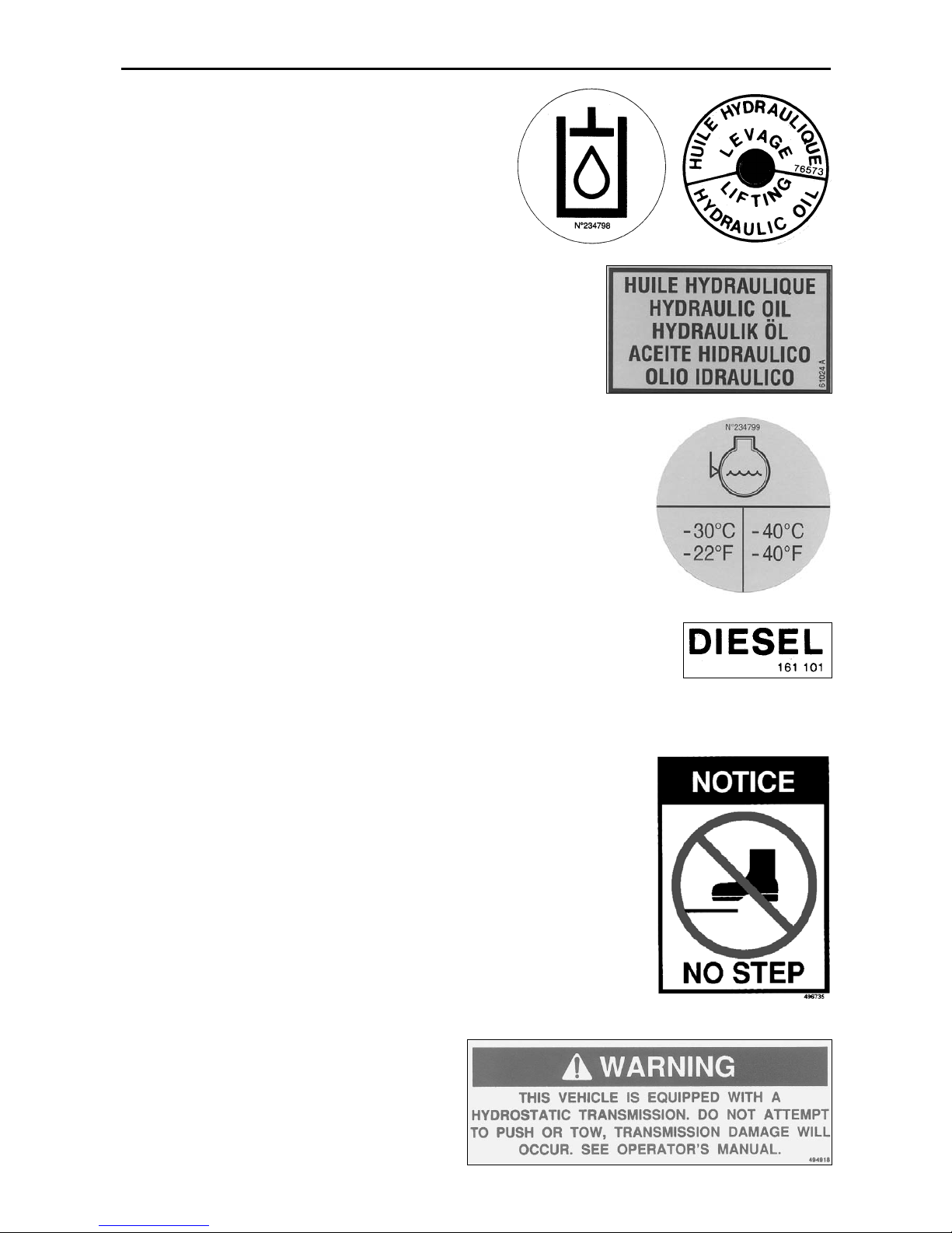
SAFETY DECALS
The purpose of this chapter is to introduce you to the safety messages, decals, and nameplates found on
your forklift truck. The decals are identified by name, part number, location, and a brief description. (The
forklift model logos, and other misc. decals not shown, can be found in your forklift parts manual.) The
decals illustrated may not be exactly the same as those installed on your forklift; installation of the decals
varies depending on the forklift model, series, decal updates, etc.. The size and location of some decals
limit the amount of information that can be placed upon it. For this reason, additional detailed information
not found on the decals is provided through-out this manual.
Every decal placed on the lift truck is important; they are constant reminders of safety and instructions that
should never be taken for granted. Even experienced operators can be seriously injured or killed by ignoring, refusing to enforce, or forgetting to follow safe operating procedures! Do not assume you know all safety issues concerning the decals. Before operating the lift truck; learn the meaning(s) of the decals as
described in this manual. If any decal becomes illegible or missing, have it replaced immediately! Always
replace decals using the same decal part no., unless otherwise specified by the manufacturer. For replacement decals not found in your parts manual, contact your nearest dealer. If you have any questions, contact
your supervisor or nearest dealer for advice before operating your forklift!
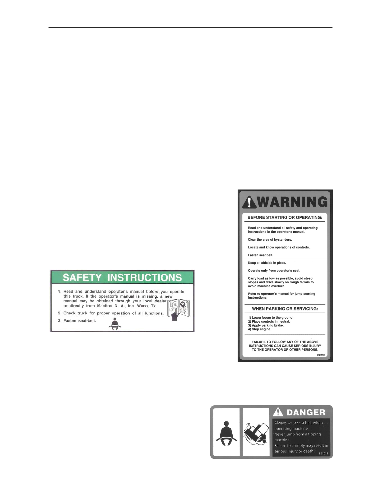
Before Starting - 801011
(Boom equipped models). Location: on the brake fluid cover panel (to
the left and below the dash panel).
Safety Instructions - 420792
(Mast equipped models). Location: on or near the operator manual
storage case, and/or on the dash panel.
Instructions for the forklift operator; before operating the forklift.
Use of Seat Belt - 801012
(Boom equipped models). Location: to the right of the
operator, near the hydraulic control lever.
Instructs the operator to always wear the seat belt during
operations, and never jump from an over-turning forklift.
X
801011
Page 15
SAFETY DECALS
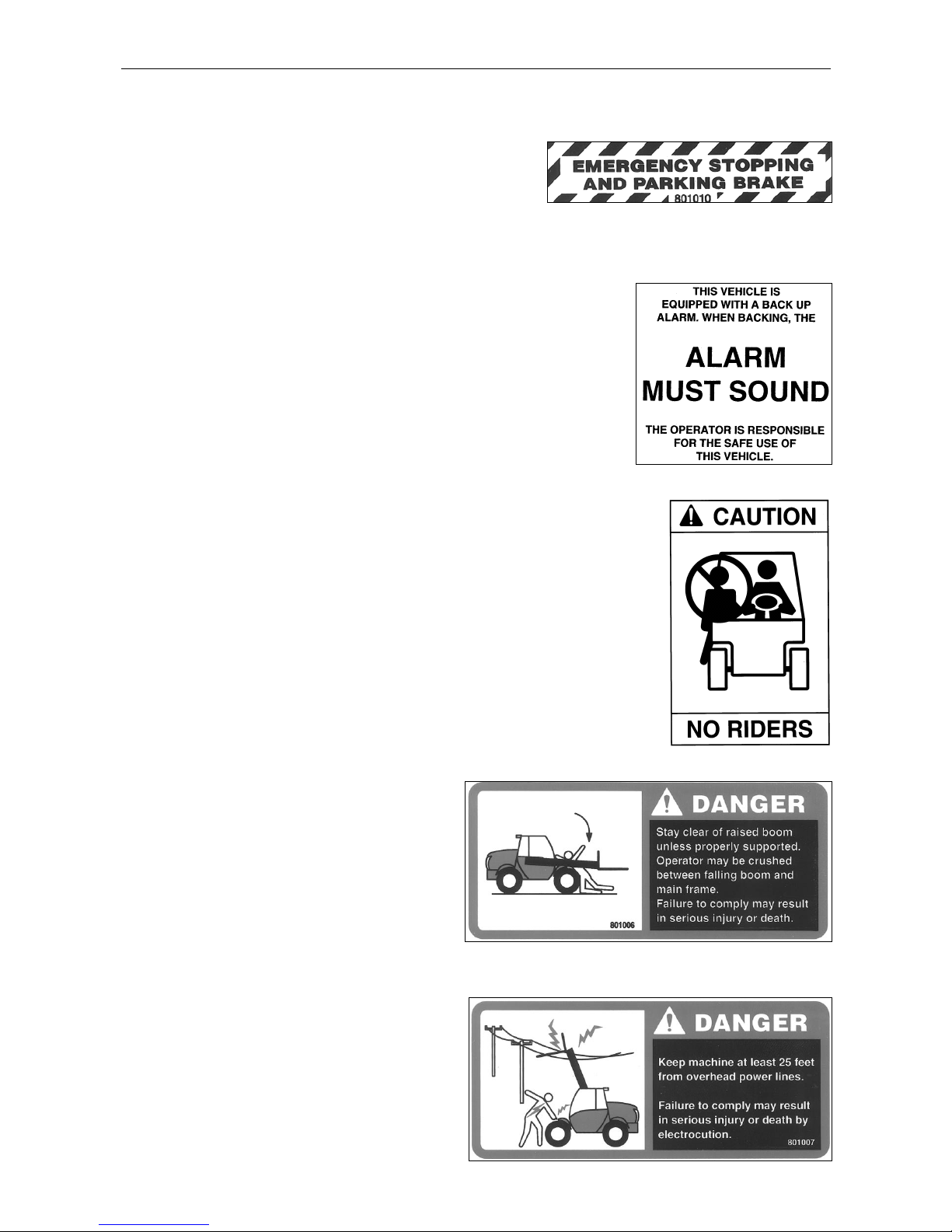
Emergency and Parking Brake - 801010
Location: near the park brake lever.
Identifies the Emergency/Parking Brake Lever.
Alarm Must Sound - 496162
Location: on the dash, in direct view of the operator.
The backup alarm must sound when the forklift is placed in reverse gear.
No Riders - 420732
Location: on the cab entrance(s), and on or near wheel fenders and engine
cover.
Informs: riders are not allowed on the forklift.
Clear of Raised Boom - 801006
(Boom equipped models). Location: on both sides
of the boom nose.
Keep away from unsupported boom.
Clear of Power Lines - 801007
(Boom equipped models). Location: on both sides
of the boom nose.
Keep away from power lines.
XI
Page 16
SAFETY DECALS
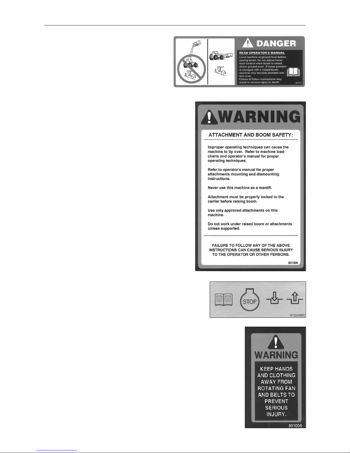
Use of Frame Leveling - 801013
(Boom equipped models). Location: to the right of
the operator near the hydraulic control lever.
Frame leveling notice; load must be lowered.
Attachment and Boom Safety - 801009
(Boom equipped models). Location: on both sides of the
boom nose.
Important reminders of attachment and boom safety.
Hydraulic Coupling - 234805
Location: near the quick-disconnect adapters.
Stop the engine and release hydraulic pressure before changing
attachments.
Rotating Fan and Belt(s) - 801008
Location: on the radiator near the fan, and on any fan belt/pulley cover(s).
Keep hands and clothing away from rotating fan and belts.
XII
Page 17

SAFETY DECALS
Gear Shift Pattern - 33460
(4-speed transmission models). Location: near the gear shift lever.
Identifies the gear shift pattern of the forklift transmission.
Steering Mode - 184276
(4 wheel steer equipped models). Location: near the steering mode selection lever.
Identifies the steering mode selection.
Mineral Oil (Brake Reservoir) - 221322 or 234800 has
been replaced by 164091.
Location: near the brake fluid reservoir where applicable.
Refer to the Operator/Service Manual for the correct brake fluid
(mineral oil) to be used in the brake system.
XIII
221322
234800
Page 18
SAFETY DECALS
Hydraulic Oil - 234798 or 76573
Location: on the hydraulic tank or filler cap.
Identifies the hydraulic reservoir (tank) or filler cap.
Hydraulic Oil - 61024
Location: on the hydraulic tank.
Identifies the hydraulic reservoir (tank).
Anti-Freeze - 234799
Location: on the radiator, near the radiator filler cap.
Indicates required minimum to maximum anti-freeze protection (-22
0
F to -400F).
Diesel Fuel - 161101
Location: on the fuel tank, near the filler cap.
Identifies the fuel tank, and use of diesel fuel.
No Step - 496735
Location: varies, depending on the forklift model.
Instructs personnel not to use the designated area as a step.
Do Not Tow - 494918
(Hydrostatic equipped models). Location: on the
dash, in view of the operator.
Towing the forklift will damage the transmission;
refer to the operator’s manual.
XIV
Page 19
SAFETY
DECALS
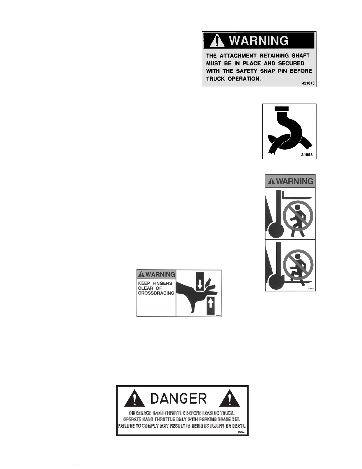
Attachment Warning - 421016
(Boom equipped models). Location: on the boom coupler,
near where the retaining shaft is installed.
Reminder to operator; install attachment retaining shaft and
safety pin before operations.
Hook Here - 24653
Location: at points provided on the forklift, where straps or chains may be attached to
secure the forklift to a trailer during transport.
Fork Safety - 426641
(Mast equipped models). Location: on the front and back side of the mast’s outer rails,
at eye level (4 required).
Instructs personnel not to travel beneath or upon the lift truck forks.
Pinch Point, Large, 2.5 x 4.5 in. - 426643
Pinch Point, Small, 1.5 x 2.75 in. - 426642
(Mast equipped models). Location: on the front and rear sides
of the mast cross bracing.
Keep fingers away from the mast
crossbracing.
HAND THROTTLE DANGER - 804784
(Boom equipped models, option). Location: Near the hand throttle mechanism.
Reminder to operator; set parking brake before operating hand throttle.
Disengage hand throttle before leaving the forklift.
XV
Page 20

SAFETY DECALS
Acid in Battery - 801014
Location: in or near the battery
storage compartment.
Addresses battery hazards.
Jump Start Battery - 801015
Location: in or near the battery storage
compartment.
Jump start instructions.
Attachment Plate - 425995
Location: on the optional removeable forklift attachment.
Important manufacturer information about the attachment. Record this information for use
when contacting the maufacturer for parts and service.
Overhead Guard Data Plate - B6109
Location: attached to the overhead guard.
Overhead guard conformity.
Forklift Data Plate - 496550
(Boom equipped models)
Forklift Data Plate - 496538
(Mast equipped models)
Location: within the operator’s compartment.
Important forklift truck identification. Record
this information for use when contacting the
manufacturer for parts and service.
XVI
496550
496538
Page 21

THE TEXTS AND ILLUSTRATIONS IN THIS DOCUMENT MUST NOT BE REPRODUCED EITHER WHOLLY OR IN PART.
1 - OPERATING AND SAFETY INSTRUCTIONS
2 - DESCRIPTION
3 - MAINTENANCE
4 - PICKING UP THE ATTACHMENTS
16/04/2007
12/10/2007
1ST DATE OF ISSUE
UP DATING
ADDING :
MT 728 Série C-E2
MT 732 Série C-E2
MT 732 Turbo Série C-E2
MT 928 Série C-E2
MT 932 Série C-E2
MT 932 Turbo Série C-E2
Page 22
Page 23

1 - 1
1 -
1 -
OPERATING
OPERATING
AND SAFETY
AND SAFETY
INSTRUCTIONS
INSTRUCTIONS
Page 24

1 - 2
Page 25

1 - 3
TABLE OF CONTENTS
INSTRUCTIONS TO THE COMPANY MANAGER
THE OPERATOR
THE LIFT TRUCK
A - THE LIFT TRUCK'S SUITABILITY FOR THE JOB
B - ADAPTATION OF THE LIFT TRUCK TO STANDARD ENVIRONMENTAL CONDITIONS
C - MODIFICATION OF THE LIFT TRUCK
THE INSTRUCTIONS
THE MAINTENANCE
INSTRUCTIONS FOR THE OPERATOR
PREAMBULE
GENERAL INSTRUCTIONS
A - OPERATOR'S MANUAL
B - AUTHORIZATION FOR USE
(see current legislation in other countries)
C - MAINTENANCE
D - MODIFICATION OF THE LIFT TRUCK
E - LIFTING PEOPLE
OPERATING INSTRUCTIONS UNLADEN AND LADEN
A - BEFORE STARTING THE LIFT TRUCK
B - DRIVER’S OPERATING INSTRUCTIONS
C - ENVIRONMENT
D - VISIBILITY
E - STARTING THE LIFT TRUCK
F - DRIVING THE LIFT TRUCK
G - STOPPING THE LIFT TRUCK
H - DRIVING THE LIFT TRUCK ON THE PUBLIC HIGHWAY
INSTRUCTIONS FOR HANDLING A LOAD
A - CHOICE OF ATTACHMENTS
B - MASS OF LOAD AND CENTRE OF GRAVITY
C - N/A
D - TRANSVERSE ATTITUDE OF THE LIFT TRUCK
E - TAKING UP A LOAD ON THE GROUND
F - TAKING UP AND LAYING A HIGH LOAD ON TYRES
MAINTENANCE INSTRUCTIONS OF THE LIFT TRUCK
GENERAL INSTRUCTIONS
MAINTENANCE
LUBRICANT AND FUEL LEVELS
HYDRAULIC
ELECTRICITY
WELDING
WASHING THE LIFT TRUCK
IF THE LIFT TRUCK IS NOT TO BE USED FOR A LONG TIME
INTRODUCTION
PREPARING THE LIFT TRUCK
PROTECTING THE I.C. ENGINE
PROTECTING THE LIFT TRUCK
BRINGING THE LIFT TRUCK BACK INTO SERVICE
1 - 4
1 - 4
1 - 4
1 - 4
1 - 4
1 - 5
1 - 5
1 - 5
1 - 6
1 - 6
1 - 6
1 - 6
1 - 6
1 - 6
1 - 6
1 - 7
1 - 8
1 - 8
1 - 8
1 - 9
1 - 9
1 - 10
1 - 10
1 - 11
1 - 12
1 - 14
1 - 14
1 - 14
1 - 14
1 - 15
1 - 15
1 - 16
1 - 18
1 - 18
1 - 18
1 - 18
1 - 18
1 - 18
1 - 19
1 - 19
1 - 20
1 - 20
1 - 20
1 - 20
1 - 20
1 - 21
Page 26

1 - 4
INSTRUCTIONS TO THE COMPANY MANAGER
THE OPERATOR
- Only qualified, authorized personnel can use the lift truck. This authorization is given in writing by the appropriate person in the
establishment with respect to the use of lift trucks and must be carried permanently by the operator.
On the basis of experience, there are a number of possible situations in which operating the lift truck is contra-indicated.
Such foreseeable abnormal uses, the main ones being listed below, are strictly forbidden.
- The foreseeable abnormal behaviour resulting from ordinary neglect, but does not result from any wish to put the machinery to any
improper use.
- The reflex reactions of a person in the event of a malfunction, incident, fault, etc. during operation of the lift truck.
- Behaviour resulting from application of the "principle of least action" when performing a task.
- For certain machines, the foreseeable behaviour of such persons as: apprentices, teenagers, handicapped persons, trainees
tempted to drive a lift truck, operator tempted to operate a truck to win a bet, in competition or for their own personal experience.
The person in charge of the equipment must take these criteria into account when assessing whether or not a person will make
a suitable driver.
THE LIFT TRUCK
A - THE TRUCK'S SUITABILITY FOR THE JOB
- MANITOU has ensured that this lift truck is suitable for use under the standard operating conditions defined in this operator's
manual, with a STATIC test coefficient of 1.33 and a DYNAMIC test coefficient of 1, as specified in harmonized norm EN 1459
for variable range trucks.
- Before commissioning, the company manager must make sure that the lift truck is appropriate for the work to be done,
and perform certain tests (in accordance with current legislation).
B - ADAPTATION OF THE LIFT TRUCK TO STANDARD ENVIRONMENTAL CONDITIONS
- In addition to series equipment mounted on your lift truck, many options are available, such as: road lighting, stop lights, flashing
light, reverse lights, reverse buzzer alarm, front light, rear light, light at the jib head, etc.
- The operator must take into account the operating conditions to define the lift truck's signalling and lighting equipment.
Contact your dealer.
- Take into account climatic and atmospheric conditions of the site of utilisation.
. Protection against frost (see: 3 - MAINTENANCE: LUBRICANTS AND FUEL).
. Adaptation of lubricants (ask your dealer for information).
. I.C. engine filtration (see: 3 - MAINTENANCE: FILTERS CARTRIDGES AND BELTS).
For operation under average climatic conditions, i.e.: between - 15 °C and + 35 °C, correct levels of lubricants in all the circuits are checked
in production. For operation under more severe climatic conditions, before starting up, it is necessary to drain all the circuits, then ensure
correct levels of lubricants using lubricants properly suited to the relevant ambient temperatures. It is the same for the cooling liquid.
- A lift truck operating in an area without fire extinguishing equipment must be equipped with an individual extinguisher. There are
solutions, consult your dealer.
Your lift truck is designed for outdoor use under normal atmospheric conditions and indoor use in suitably aerated and ventilated premises.
It is prohibited to use the lift truck in areas where there is a risk of fire or which are potentially explosive (e.g. Refineries, fuel or gas depots,
stores of inflammable products…). For use in these areas, specific equipment is available (ask your dealer
for information).
- Our trucks comply with Directive 89/336/EC concerning electromagnetic compatibility (EMC), and with the corresponding
harmonized norm EN 12895. Their proper operation is no longer guaranteed if they are used within areas in which
the electromagnetic fields exceed the limit specified by that norm (10 V/m).
- Directive 2002/44/EC requires company managers to not expose their employees to excessive vibration doses. There is no
recognized code of measurement for comparing the machines of different manufacturers. The actual doses received can
therefore be measured only under actual operating conditions at the user's premises.
- The following are some tips for minimizing these vibration doses:
• Select the most suitable lift truck and attachment for the intended use.
• Adapt the seat adjustment to the operator's weight (according to lift truck model) and maintain it in good condition,
as well as the cab suspension. Inflate the tires in accordance with recommendations.
• Ensure that the operators adapt their operating speed to suit the conditions on site.
• As far as possible, arrange the site in such a way as to provide a flat running surface and remove obstacles and harmful
potholes.
Page 27

1 - 5
C - MODIFICATION OF THE LIFT TRUCK
- For your safety and that of others, you must not change the structure and settings of the various components used in your lift
truck (hydraulic pressure, calibrating limiters, I.C. engine speed, addition of extra equipment, addition of counterweight,
unapproved attachments, alarm systems, etc.) yourself. In this event, the manufacturer cannot be held responsible.
THE INSTRUCTIONS
- The operator's manual must always be in good condition and kept in the place provided on the lift truck and in the language used
by the operator.
- The operator's manual and any plates or stickers which are no longer legible or are damaged, must be replaced immediately.
THE MAINTENANCE
- Maintenance or repairs other than those detailed in part: 3 - MAINTENANCE must be carried out by qualified personnel (consult
your dealer) and under the necessary safety conditions to maintain the health of the operator and any third party.
Your lift truck must be inspected periodically to ensure that it remains in compliance. The frequency of this inspection is defined by current
legislation in the country in which the lift truck is used.
Page 28

1 - 6
INSTRUCTIONS FOR THE OPERATOR
PREAMBULE
WHENEVER YOU SEE THIS SYMBOL IT MEANS:
WARNING ! BE CAREFUL ! YOUR SAFETY OR THE SAFETY OF THE LIFT TRUCK IS AT RISK.
The risk of accident while using, servicing or repairing your lift truck can be restricted if you follow the safety instructions and safety
measures detailed in these instruction.
- Only the operations and manœuvres described in these operator's manual must be performed. The manufacturer cannot predict
all possible risky situations. Consequently, the safety instructions given in the operator's manual and on the lift truck itself are
not exhaustive.
- At any time, as an operator, you must envisage, within reason, the possible risk to yourself, to others or to the lift truck itself
when you use it.
Failure to respect the safety and operating instructions, or the instructions for repairing or servicing your lift truck may lead to serious, even
fatal accident.
GENERAL INSTRUCTIONS
A - OPERATOR'S MANUAL
- Read the operator's manual carefully.
- The operator's manual must always be in good condition and in the place provided for it on the lift truck.
- You must report any plates and stickers which are no longer legible or which are damaged.
B - AUTHORIZATION FOR USE
(see current legislation in other countries)
- Only qualified, authorized personnel may use the lift truck. This authorization is given in writing by the appropriate person in the
company, in charge of using the lift truck, and must be permanently carried by the operator.
- The operator is not competent to authorise the driving of the lift truck by another person.
C - MAINTENANCE
- The operator must immediately advise his superior if his lift truck is not in good working order or does not comply with the safety
notice.
- The operator is prohibited from carrying out any repairs or adjustments himself, unless he has been trained for this purpose. He
must keep the lift truck properly cleaned if this is among his responsibilities.
- The operator must carry out daily maintenance (see: 3 - MAINTENANCE: A - DAILY OR EVERY 10 HOURS SERVICE).
- The operator must ensure tyres are adapted to the nature of the ground (see area of the contact surface of the tyres in the
chapter: 2 - DESCRIPTION: CHARACTERISTICS). There are optional solutions, consult your dealer.
. SAND tyres.
. LAND tyres.
. Snow chains.
Do not use the lift truck if the tyres are incorrectly inflated, damaged or excessively worn, because this could put your own safety or that
of others at risk, or cause damage to the lift truck itself. The fitting of foam inflated tyres is prohibited and is not guaranteed by the
manufacturer, excepting prior authorisation.
D - MODIFICATION OF THE LIFT TRUCK
- For your safety and that of others, you must not change the structure and settings of the various components used in your lift
truck (hydraulic pressure, calibrating limiters, I.C. engine speed, addition of extra equipment, addition of counterweight,
unapproved attachments, alarm systems, etc.) yourself. In this event, the manufacturer cannot be held responsible.
Page 29

1 - 7
E - LIFTING PEOPLE
- The use of working equipment and/or load lifting attachments to lift people is:strictly forbidden.
Page 30

1 - 8
OPERATING INSTRUCTIONS UNLADEN AND LADEN
A - BEFORE STARTING THE LIFT TRUCK
- Carry out daily maintenance (see: 3 - MAINTENANCE: A - DAILY OR EVERY 10 HOURS SERVICE).
- Make sure the lights, indicators and windscreen wipers are working properly.
- Make sure the rear view mirrors are in good condition, clean and properly adjusted.
- Make sure the horn works.
B - DRIVER’S OPERATING INSTRUCTIONS
- Whatever his experience, the operator is advised to familiarize himself with the position and operation of all the controls and
instruments before operating the lift truck.
- Wear clothes suited for driving the lift truck, avoid loose clothes.
- Make sure you have the appropriate protective equipment for the job to be done.
- Prolonged exposure to high noise levels may cause hearing problems. It is recommended to wear ear muffs to protect against
excessive noise.
- Always face the lift truck when getting into and leaving the driving seat and use the handle(s) provided for this purpose. Do not
jump out of the seat to get down.
- Always pay attention when using the lift truck. Do not listen to the radio or music using headphones or earphones.
- Never operate the lift truck when hands or feet are wet or soiled with greasy substances.
- For increased comfort, adjust the seat to your requirements and adopt the correct position in the driver’s cab.
Under no circumstances must the seat be adjusted while the lift truck is moving.
- The operator must always be in his normal position in the driver’s cab. It is prohibited to have arms or legs, or generally any part
of the body, protruding from the driver’s cab of the lift truck.
- The safety belt must be worn and adjusted to the operator's size.
- The control units must never in any event be used for any other than their intended purposes (e.g. climbing onto or down from
the lift truck, portmanteau, etc.).
- If the control components are fitted with a forced operation (lever lock) device, it is forbidden to leave the cab without first putting
these controls in neutral.
- It is prohibited to carry passengers either on the lift truck or in the cab.
Page 31

1 - 9
C - ENVIRONMENT
- Comply with site safety regulations.
- If you have to use the lift truck in a dark area or at night, make sure it is equipped with working lights.
- During handling operations, make sure that no one is in the way of the lift truck and its load.
- Do not allow anybody to come near the working area of the lift truck or pass beneath an elevated load.
- When using the lift truck on a transverse slope, before lifting the jib, follow the instructions given in the paragraph: INSTRUCTIONS
FOR HANDLING A LOAD: D - TRANSVERSE ATTITUDE OF THE LIFT TRUCK.
- Travelling on a longitudinal slope:
• Drive and brake gently.
• Moving without load: Forks or attachment facing downhill.
• Moving with load: Forks or attachment facing uphill.
- Take into account the lift truck’s dimensions and its load before trying to negotiate a narrow or low passageway.
- Never move onto a loading platform without having first checked:
• That it is suitably positioned and made fast.
• That the unit to which it is connected (wagon, lorry, etc.) will not shift.
• That this platform is prescribed for the total weight of the lift truck to be loaded.
• That this platform is prescribed for the size of the lift truck.
- Never move onto a foot bridge, floor or freight lift, without being certain that they are prescribed for the weight and size of the lift
truck to be loaded and without having checked that they are in sound working order.
- Be careful in the area of loading bays, trenches, scaffolding, soft land and manholes.
- Make sure the ground is stable and firm under the wheels and/or stabilizers before lifting or removing the load. If necessary, add
sufficient wedging under the stabilizers.
- Make sure that the scaffolding, loading platform, pilings or ground is capable of bearing the load.
- Never stack loads on uneven ground, they may tip over.
If the load or the attachment must remain above a structure for a long time, there is the risk that it will rest on the structure because of
the jib descending owing to the oil in the cylinders cooling down.
To eliminate this risk:
- Regularly check the distance between the load or the attachment and the structure and readjust this if necessary.
- If possible use the lift truck at an oil temperature as close as possible to ambient temperature.
- In the case of work near aerial lines, ensure that the safety distance is sufficient between the working area of the lift truck and
the aerial line.
You must consult your local electrical agency. You could be electrocuted or seriously injured if you operate or park the lift truck to o clo s e
to power cables.
In the event of high winds, do not carry out handling work that jeopardizes the stability of the lift truck and its load, particularly if the load
catches the wind badly.
D - VISIBILITY
- The safety of people within the lift truck's working area, as well as that of the lift truck itself and the operator are depend on
good operator visibility of the lift truck's immediate vicinity in all situations and at all times.
- This lift truck has been designed to allow good operator visibility (direct or indirect by means of rear-view mirrors) of the immediate
vicinity of the lift truck while traveling with no load and with the jib in the transport position.
- Special precautions must be taken if the size of the load restricts visibility towards the front:
- moving in reverse,
- site layout,
- assisted by a person directing the maneuver (while standing outside the truck's area of travel), making sure to keep this
person clearly in view at all times.
- in any case, avoid reversing over long distances.
- Certain special accessories may require the truck to travel with the jib in the raised position. In such cases, visibility on the right
hand side is restricted, and special precautions must be taken:
- site layout,
- assisted by a person directing the maneuver (while standing outside the truck's area of travel).
- If visibility of your road is inadequate, ask someone to assist by directing the maneuver (while standing outside the truck's area
of travel), making sure to keep this person clearly in view at all times.
- Keep all components affecting visibility in a clean, properly adjusted state and in good working order (e.g. windscreens, windows,
windscreen wipers, windscreen washers, driving and work lights, rear-view mirrors).
Page 32

1 - 10
E - STARTING THE LIFT TRUCK
SAFETY NOTICE
The lift truck must only be started up or manoeuvred when the operator is sitting in the driver’s cab, with his seat belt adjusted and
fastened.
- Never try to start the lift truck by pushing or towing it. Such operation may cause severe damage to the transmission. If
necessary, to tow the lift truck in an emergency, the transmission must be placed in the neutral position (see: 3 - MAINTENANCE:
G - OCCASIONAL MAINTENANCE).
- If using an emergency battery for start-up, use a battery with the same characteristics and respect battery polarity when
connecting it. Connect at first the positive terminals before the negative terminals.
Failure to respect polarity between batteries can cause serious damage to the electrical circuit. The electrolyte in the battery may produce
an explosive gas. Avoid flames and generation of sparks close to the batteries. Never disconnect a battery while it is charging.
INSTRUCTIONS
- Check the closing and locking of the hood(s).
- Make sure that the forward/reverse lever is in neutral.
- Turn the ignition key to the position I to activate the electrical system.
- Make sure the signal lights on the instrument control panel and fuel level indicators are working properly (see: 2 - DESCRIPTION:
INSTRUMENTS AND CONTROLS).
- Turn the ignition key to position II to preheat for 5 seconds and turn the ignition key fully: the I.C. engine should then start.
Release the ignition key and let the I.C. engine run at idle.
- Do not engage the starter motor for more than 15 seconds and carry out the preheating for 5 seconds between unsuccessful
attempts.
- Make sure all the signal lights on the control instrument panel are off.
- Check all control instruments when the I.C. engine is warm and at regular intervals during use, so as to quickly detect any faults
and to be able to correct them without any delay.
- If an instrument does not show the correct display, stop the I.C. engine and immediately carry out the necessary operations.
F - DRIVING THE LIFT TRUCK
SAFETY NOTICE
Operators' attention is drawn to the risks involved in using the lift truck, in particular:
- Risk of losing control.
- Risk of losing lateral and frontal stability of the lift truck.
The operator must remain in control of the lift truck.
In the event of the lift truck overturning, do not try to leave the cabin during the incident. YOUR BEST PROTECTION IS TO STAY
FASTENED IN THE CABIN.
- Observe the company’s traffic regulations or, by default, the public highway code.
- Do not carry out operations which exceed the capacities of your lift truck or attachments.
- Always drive the lift truck with the forks or attachment to the transport position, i.e. at 12 in. from the ground, the jib retracted
and the carriage sloping backwards.
- Only carry loads which are balanced and properly anchored to avoid any risk of a load falling off.
- Ensure that palettes, cases, etc, are in good order and suitable for the load to be lifted.
- Familiarise yourself with the lift truck on the terrain where it will be used.
- Ensure that the service brakes are working properly.
- The loaded lift truck must not travel at speeds in excess of 8 mph.
- Drive smoothly at an appropriate speed for the operating conditions (land configuration, load on the lift truck).
- Do not use the hydraulic jib controls when the lift truck is moving.
- Do not manoeuvre the lift truck with the jib in the raised position unless under exceptional circumstances and then with extreme
caution, at very low speed and using gentle braking. Ensure that visibility is adequate.
- Take bends slowly.
- In all circumstances make sure you are in control of your speed.
- On damp, slippery or uneven terrain, drive slowly.
- Brake gently, never abruptly.
- Only use the lift truck’s forward/reverse lever from a stationary position and never do so abruptly.
- Do not drive with your foot on the brake pedal.
- Always remember that hydrostatic type steering is extremely sensitive to movement of the steering wheel, so turn it gently and
not jerkily.
- Never leave the I.C. engine on when the lift truck is unattended.
- Do not leave the cab when the lift truck has a raised load.
- Look where you are going and always make sure you have good visibility along the route.
Page 33

1 - 11
- Use the rear-view mirrors frequently.
- Drive around obstacles.
- Never drive on the edge of a ditch or steep slope.
- It is dangerous to use two lift trucks simultaneously to handle heavy or voluminous loads, since this operation requires particular
precautions to be taken. It must only be used exceptionally and after risk analysis.
- The ignition switch has an emergency stop mechanism in case of an operating anomaly occurring in the case of lift trucks not
fitted with a punch-operated cut-out.
INSTRUCTIONS
- Always drive the lift truck with the forks or attachment to the transport position, i.e. at 12 in. from the ground, the jib retracted
and the carriage sloping backwards.
- For lift trucks with gearboxes, use the recommended gear (see: 2 - DESCRIPTION: INSTRUMENTS AND CONTROLS).
- Select the steering mode appropriate for its use and/or working conditions (see: 2 - DESCRIPTION: INSTRUMENTS AND
CONTROLS) (as model of lift truck).
- Release the parking brake.
- Shift the forward/reverse lever to the selected direction of travel and accelerate gradually until the lift truck moves off.
G - STOPPING (PARKING) THE LIFT TRUCK
SAFETY NOTICE
- Never leave the ignition key in the lift truck during the operator's absence.
- When the lift truck is stationary, or if the operator has to leave his cab (even for a moment), place the forks or attachment on
the ground, apply the parking brake and put the forward/reverse lever in neutral.
- Make sure that the lift truck is not stopped in any position that will interfere with the traffic flow and at least than 6 feet from
the track of a railway.
- In the event of prolonged parking on a site, protect the lift truck from bad weather, particularly from frost (check the level of
antifreeze), close and lock all the lift truck accesses (doors, windows, cowls…).
INSTRUCTIONS
- Park the lift truck on flat ground or on an incline of less than 15 %.
- Place the forward/reverse lever in neutral.
- Apply the parking brake.
- For lift trucks with gearboxes, place the gear lever in neutral.
- Retract entirely the jib.
- Lower the forks or attachment to rest on the ground.
- When using an attachment with a grab or jaws, or a bucket with hydraulic opening, close the attachment fully.
- Before stopping the lift truck after a long working period, leave the I.C. engine idling for a few moments, to allow the coolant liquid
and oil to lower the temperature of the I.C. engine and transmission. Do not forget this precaution, in the event of frequent stops
or warm stalling of the I.C. engine, or else the temperature of certain parts will rise significantly due to the stopping of the cooling
system, with the risk of badly damaging such parts.
- Stop the I.C. engine with the ignition switch.
- Remove the ignition key.
- Lock all the accesses to the lift truck (doors, windows, cowls…).
Page 34

1 - 12
H - DRIVING THE LIFT TRUCK ON THE PUBLIC HIGHWAY
SAFETY INSTRUCTIONS
- Operators driving on the public highway must comply with current highway code legislation.
- The lift truck must comply with current road legislation. If necessary, there are optional solutions. Contact your dealer.
INSTRUCTIONS
- Make sure the revolving light is in place, switch it on and verify its operation.
- Check the good working order and cleanness of lights, indicators and windscreen wiper.
- Switch off the working headlights if the lift truck is fitted with them.
- Select the steering mode "HIGHWAY TRAFFIC" (as model of lift truck) (see: 2 - DESCRIPTION: INSTRUMENTS AND CONTROLS).
- Retract entirely the jib and put the attachment at 12 in. from the ground.
- Place the slope correctors in the central position, i.e. the transverse shaft of the axles parallel to the chassis (as model of lift
truck).
- Lift up the stabilizers to the maximum and turn the blocks inwards (as model of lift truck).
- For lift trucks with gearboxes:
On the road, set off in 3rd gear and go into 4th (as model of lift truck) when the conditions and state of the road allow. In hilly
areas, set off in 2nd gear and go into 3rd when the conditions and state of the road allow.
Never move in neutral (gear reverser or gear lever in neutral or transmission cut-off button pressed) to preserve the lift truck engine brake.
Failure to respect this instruction on a slope will lead to excessive speed which may make the lift truck uncontrollable (steering, brakes)
and may cause severe mechanical damage.
Page 35

1 - 13
DRIVING THE LIFT TRUCK WITH A FRONT-MOUNTED ATTACHMENT
- You must comply with current regulations in your countr y, covering the possibility of driving on the public highway with a frontmounted attachment on your lift truck.
- If road legislation in your country authorizes circulation with a front-mounted attachment, you must at least:
• Protect and repor t any sharp and/or dangerous edges on the attachment (see: 4 - ADAPTABLE ATTACHMENTS IN
OPTION ON THE RANGE: ATTACHMENT SHIELDS).
• The attachment must not be loaded.
• Make sure that the attachment does not mask the lighting range of the forward lights.
• Make sure that current legislation in your country does not require other obligations.
OPERATING THE LIFT TRUCK WITH A TRAILER
- For using a trailer, observe the regulations in force in your country (maximum travel speed, braking, maximum weight of trailer,
etc.).
- Do not forget to connect the trailer’s electrical equipment to that of the lift truck.
- The trailer's braking system must comply with current legislation.
- If pulling a trailer with assisted braking, the tractor lift truck must be equipped with a trailer braking mechanism. In this case, do
not forget to connect the trailer braking equipment to the lift truck.
- The maximum vertical pull on the trailer hook must not exceed 3300 ft/lb.
- The authorised maximum train weight must not exceed the maximum weight authorised by the manufacturer (consult the
manufacturer’s plate on your lift truck).
- For lift trucks with gearboxes:
When driving with a trailer, set off in 2nd gear and go into 3rd when the conditions and state of the road allow. Do not exceed
4th gear to avoid overheating the internal combustion engine and the transmission.
IF NECESSARY, CONSULT YOUR DEALER.
Page 36

1 - 14
INSTRUCTIONS FOR HANDLING A LOAD
A - CHOICE OF ATTACHMENTS
- Only attachments approved by MANITOU can be used on its lift trucks.
- Make sure the attachment is appropriate for the work to be done (see: 4 - ADAPTABLE ATTACHMENTS IN OPTION ON THE RANGE).
- Make sure the attachment is correctly installed and locked onto the lift truck carriage.
- Make sure that your lift truck attachments work properly.
- Comply with the load chart limits for the lift truck for the attachment used.
- Do not exceed the rated capacity of the attachment.
- Never lift a load in a sling without the attachment provided for the purpose. There are optional solutions ; contact your dealer.
B - MASS OF LOAD AND CENTRE OF GRAVITY
- Before taking up a load, you must know its mass and its centre of gravity.
- The load chart for your lift truck is valid for a load in which the longitudinal position of the
centre of gravity is 24 in. from the base of the forks (fig. B1). For a higher centre of gravity,
contact your dealer.
- For irregular loads, determine the transverse centre of gravity before any movement (fig.
B2) and set it in the longitudinal axis of the lift truck.
It is forbidden to move a load heavier than the effective capacity defined on the lift truck load
chart.
For loads with a moving centre of gravity (e.g. liquids), take account of the variations in the
centre of gravity in order to determine the load to be handled and be vigilant and take extra
care to limit these variations as far as possible.
C - N/A
500 mm
B1
B2
24 IN.
Page 37

1 - 15
D - TRANSVERSE (HORIZONTAL) ATTITUDE OF THE LIFT TRUCK
(depending on the model of lift truck)
The transverse attitude is the transverse slope of the chassis with respect to the
horizontal.
Raising the jib reduces the lift truck's lateral stability. The transverse attitude must be set
with the jib in down position as follows:
1 - LIFT TRUCK WITHOUT SLOPE CORRECTOR USED ON TYRES
- Position the lift truck so that the bubble in the level is between the two lines (see: 2 DESCRIPTION: INSTRUMENTS AND CONTROLS).
2 - LIFT TRUCK WITH SLOPE CORRECTOR USED ON TYRES
- Correct the slope using the hydraulic control and verify the horizontality via the level. The
bubble in the level must be between the two lines (see: 2 - DESCRIPTION: INSTRUMENTS
AND CONTROLS).
3 - LIFT TRUCK USED ON STABILIZERS
- Set the two stabilizers on the ground and raise the two front wheels of the lift truck (fig.
D1).
- Correct the slope using the stabilizers (fig. D2) and make sure the truck is horizontal by
checking the level. The bubble of the level must be between the two lines (see: 2 DESCRIPTION: INSTRUMENTS AND CONTROLS). In this position, the two front wheels
must be off the ground.
E - TAKING UP A LOAD ON THE GROUND
- Approach the lift truck perpendicular to the load, with the jib retracted and the forks in a
horizontal position (fig. E1).
- Adjust the fork spread and centering in connection with the load (fig. E2) (optional
solutions exist, consult your dealer).
- Never lift a load with a single fork.
Beware of the risks of trapping or squashing limbs when manually adjusting the forks.
- Move the lift truck forward slowly (1) and bring the forks to stop in front of the load (fig.
E3), if necessary, slightly lift the jib (2) while taking up the load.
- Bring the load into the transport position.
- Tilt the load far enough backwards to ensure stability (loss of load on braking or going
downhill).
FOR A NON-PALLETIZED LOAD
- Tilt the carriage (1) forwards and move the lift truck slowly forwards (2), to insert the fork
under the load (fig. E4) (block the load if necessary).
- Continue to move the lift truck forwards (2) tilting the carriage (3) (fig. E4) backwards to
position the load on the forks and check the load's longitudinal and lateral stability.
D1
D2
E1
E2
1
3
2
E4
2
1
E3
Page 38

1 - 16
F - TAKING UP AND LAYING A HIGH LOAD ON TYRES
You must not raise the jib if you have not checked the transverse attitude of the lift truck (see:
INSTRUCTIONS FOR HANDLING A LOAD: D - TRANSVERSE ATTITUDE OF THE LIFT TRUCK).
REMINDER: Make sure that the following operations can be performed with good visibility
(see: OPERATIONS INSTRUCTIONS UNLADEN AND LADEN: D - VISIBILITY).
TAKING UP A HIGH LOAD ON TYRES
- Ensure that the forks will easily pass under the load.
- Lift and extend the jib (1) (2) until the forks are level with the load, moving the lift truck
(3) forward if necessary (fig. F1), moving very slowly and carefully.
- Always think about keeping the distance necessary to fit the forks under the load,
between the pile and the lift truck (fig. F1) and use the shortest possible length of jib.
- Stop the forks in front of the load by alternately extending and retracting the jib (1) or, if
necessary, moving the lift truck forward (2) (fig. F2). Put the handbrake on and set the
reverse gear to neutral.
- Slightly lift the load (1) and incline the carriage (2) backwards to stabilize the load (fig.
F3).
- Tilt the load sufficiently backwards to ensure its stability.
- Watch the load closely. (If the load is unstable or the lift truck is overloaded, replace the
load in the place from which it was taken.)
- If possible lower the load without shifting the lift truck. Lift the jib (1) to release the load,
retract (2) and lower the jib (3) to bring the load into the transport position (fig. F4).
- If this is not possible, back up the lift truck (1), manoeuvring very gently and carefully to
release the load. Retract (2) and lower the jib (3) to bring the load into the transport
position (fig. F5).
1
2
3
F1
1
2
F2
2
1
F3
3
2
1
F4
1
3
2
F5
Page 39

1 - 17
LAYING A HIGH LOAD ON TYRES
- Approach the load in the transport position in front of the pile (fig. F6).
- Put the handbrake on and set the reversing lever to neutral.
- Use the Load Charts to confirm the load and lift height capacities. Lift and extend the jib
(1) (2) until the load is above the pile. If necessary, move the lift truck (3) forward (fig.
F7), driving very slowly and carefully.
- Place the load in a horizontal position and lay it down on the pile by lowering and
retracting the jib (1) (2) in order to position the load correctly (fig. F8).
- If possible, release the fork by alternately retracting and raising the jib (1) (fig. F9). Then
set the forks into transport position.
- If this is not possible, reverse the lift truck (1) very slowly and carefully to release the
forks (fig. F10). Then set them into transport position.
F6
1
2
3
F7
2
1
F8
1
F9
1
F10
Page 40

MAINTENANCE INSTRUCTIONS OF THE LIFT TRUCK
GENERAL INSTRUCTIONS
- Ensure the area is sufficiently ventilated before starting the lift truck.
- Wear clothes suitable for the maintenance of the lift truck, avoid wearing jewellery and loose clothes. Tie and protect your hair,
if necessary.
- Stop the I.C. engine and remove the ignition key, when an intervention is necessar y.
- Read the operator's manual carefully.
- Carry out all repairs immediately, even if the repairs concerned are minor.
- Repair all leaks immediately, even if the leak concerned is minor.
- Make sure that the disposal of process materials and of spare parts is carried out in total safety and in a ecological way.
- Be careful of the risk of burning and splashing (exhaust, radiator, I.C. engine, etc.).
MAINTENANCE
- Perform the periodic service (see: 3 - MAINTENANCE) to keep your lift truck in good working conditions. Failure to perform the
periodic service may cancel the contractual guarantee.
LUBRICANT AND FUEL LEVELS
- Use the recommended lubricants (never use contaminated lubricants).
- Do not fill the fuel tank when the I.C. engine is running.
- Only fill up the fuel tank in areas specified for this purpose.
- Do not fill the fuel tank to the maximum level.
- Do not smoke or approach the lift truck with a flame, when the fuel tank is open or is being filled.
HYDRAULIC
- Any work on the load handling hydraulic circuit is forbidden except for the operations described in part: 3 - MAINTENANCE.
- Do not attempt to loosen unions, hoses or any hydraulic component with the circuit under pressure.
BALANCING VALVE: For inspection, see: 3 – MAINTENANCE: D - EVERY 500 HOURS SERVICE. It is dangerous to change the setting and
remove the balancing valves or safety valves which may be fitted to your lift truck cylinders. These operations must only be performed by
approved personnel (consult your dealer).
The HYDRAULIC ACCUMULATORS that may be fitted on your lift truck are pressurised units. Removing these accumulators and their
pipework is a dangerous operation and must only be performed by approved personnel (consult your dealer).
ELECTRICITY
- Do not short-circuit the starter relay to start the IC engine. If the gear reverser is not in neutral and the parking brake is not
engaged, the lift truck may suddenly start to move.
- Do not drop metallic items on the battery.
- Disconnect the battery before working on the electrical circuit.
1 - 18
Page 41

WELDING
- Disconnect the battery before any welding operations on the lift truck.
- When carrying out electric welding work on the lift truck, connect the negative cable from the equipment directly to the part being
welded, so as to avoid high tension current passing through the alternator.
- Never carry out welding or work which gives off heat on an assembled tyre. The heat would increase the pressure which could
cause the tyre to explode.
- If the lift truck is equipped with an electronic control unit, disconnect this before starting to weld, to avoid the risk of causing
irreparable damage to electronic components.
WASHING THE LIFT TRUCK
- Clean the lift truck or at least the area concerned before any intervention.
- Remember to close and lock all accesses to the lift truck (doors, windows, cowls…).
- During washing, avoid the articulations and electrical components and connections.
- If necessary, protect against penetration of water, steam or cleaning agents, components susceptible of being damaged,
particularly electrical components and connections and the injection pump.
- Clean the lift truck of any fuel, oil or grease trace.
FOR ANY INTERVENTION OTHER THAN REGULAR MAINTENANCE, CONSULT YOUR DEALER.
1 - 19
Page 42

IF THE LIFT TRUCK IS NOT TO BE USED FOR A LONG TIME
INTRODUCTION
The following recommendations are intended to prevent the lift truck from being damaged when it is withdrawn from service for an
extended period.
For these operations, we recommend the use of approved protective products.
Instructions for using the products are given on the packaging.
Procedures to follow if the lift truck is not to be used for a long time and for starting it up again afterwards must be performed by your
dealership.
PREPARING THE LIFT TRUCK
- Clean the lift truck thoroughly.
- Check and repair any leakage of fuel, oil, water or air.
- Replace or repair any worn or damaged parts.
- Wash the painted surfaces of the lift truck in clear and cold water and wipe them.
- Touch up the paintwork if necessary.
- Shut down the lift truck (see: OPERATING INSTRUCTIONS UNLADEN AND LADEN).
- Make sure the jib cylinder rods are all in retracted position.
- Release the pressure in the hydraulic circuits.
PROTECTING THE I.C. ENGINE
- Fill the tank with fuel (see: 3 - MAINTENANCE: A - DAILY OR EVERY 10 HOURS SERVICE).
- Empty and replace the cooling liquid (see: 3 - MAINTENANCE: F - EVERY 2000 HOURS SERVICE).
- Leave the I.C. engine running at idling speed for a few minutes, then switch off.
- Replace the I.C. engine oil and oil filter (see: 3 - MAINTENANCE: D - EVERY 500 HOURS SERVICE).
- Add an approved protective product to the engine oil.
- Run the I.C. engine for a short time so that the oil and cooling liquid circulate inside.
- Disconnect the battery and store it in a safe place away from the cold, after charging it to a maximum.
- Remove the injectors and spray a protective product into each cylinder for two seconds with the piston in low neutral position.
- Turn the crankshaft once slowly and refit the injectors (see I.C. engine REPAIR MANUAL).
- Remove the intake hose from the manifold or turbocharger and spray a protective product into the manifold or turbocharger.
- Cap the intake manifold or turbocharger hole with waterproof adhesive tape.
- Remove the exhaust pipe and spray a protective product into the exhaust manifold or turbocharger.
- Refit the exhaust pipe and block the outlet with waterproof adhesive tape.
NOTE: The spray time is noted on the product packaging and must be increased by 50% for turbo engines.
- Open the filler plug, spray a protective product around the rocker arm shaft and refit the filler plug.
- Cap the fuel tank using waterproof adhesive tape.
- Remove the drive belts and store them in a safe place.
- Disconnect the engine cut-off solenoid on the injection pump and carefully insulate the connection.
PROTECTING THE LIFT TRUCK
- Set the lift truck on axle stands so that the tyres are not in contact with the ground and release the handbrake.
- Protect cylinder rods which will not be retracted, from corrosion.
- Wrap the tyres.
NOTE: If the lift truck is to be stored outdoors, cover it with a waterproof tarpaulin.
1 - 20
Page 43

BRINGING THE LIFT TRUCK BACK INTO SERVICE
- Remove the waterproof adhesive tape from all the holes.
- Refit the intake hose.
- Refit and reconnect the battery.
- Remove the protection from the cylinder rods.
- Perform the daily service (see: 3 - MAINTENANCE: A - DAILY OR EVERY 10 HOURS SERVICE).
- Put the handbrake on and remove the axle stands.
- Empty and replace the fuel and replace the fuel filter (see: 3 - MAINTENANCE: D - EVERY 500 HOURS SERVICE).
- Refit and set the tension in the drive belts (see: 3 - MAINTENANCE: C - EVERY 250 HOURS SERVICE).
- Turn the I.C. engine using the starter, to allow the oil pressure to rise.
- Reconnect the engine cut-off solenoid.
- Lubricate the lift truck completely (see: 3 - MAINTENANCE: SERVICING SCHEDULE).
Make sure the area is adequately ventilated before starting up the lift truck.
- Start up the lift truck, following the safety instructions and regulations (see: OPERATING INSTRUCTIONS UNLADEN AND LADEN).
- Run all the jib's hydraulic movements, concentrating on the ends of travel for each cylinder.
1 - 21
Page 44

1 - 22
Page 45

2 - 1
2 - DESCRIPTION
2 - DESCRIPTION
Page 46

2 - 2
Page 47

2 - 3
2 - 4
2 - 6
2 - 10
2 - 12
2 - 34
2 - 36
TABLE OF CONTENTS
IDENTIFICATION OF THE LIFT TRUCK
CH ARACTERISTICS
DIMENSIONS AND LOAD CHART
INSTRUMENTS AND CONTROLS
TOWING PIN AND HOOK
DESCRIPTION AND USE OF OPTIONS
Page 48

2 - 4
IDENTIFICATION OF THE LIFT TRUCK
As our policy is to promote a constant improvement of our products, our range of
telescopic lift trucks may undergo certain modifications, without obligation for us to advise
our customers.
When you order parts, or when you require any technical information, always specify:
NOTE: For the owner's convenience, it is recommended that a note of these numbers is
made in the spaces provided, at the time of the delivery of the lift truck.
PLATE MANUFACTURER OF THE LIFT TRUCK (FIG. A)
- Model
- Series
- Serial Nr
- Chassis Nr
- Year of manufacture
For any further technical information regarding your lift truck refer to chapter: 2 DESCRIPTION: CHARACTERISTICS.
I.C. ENGINE (FIG. B)
- I.C. engine Nr
TRANSMISSION (FIG. C)
- Type
- MANITOU reference
- Serial Nr
ANGLE GEAR-BOX (FIG. D)
- Type
- MANITOU reference
- Serial Nr
B
C
D
A
Page 49

FRONT AXLE (FIG. E)
- Type
- Serial Nr
- MANITOU reference
REAR AXLE (FIG. F)
- Type
- Serial Nr
- MANITOU reference
CAB (FIG. G)
- Type
- Serial Nr
JIB (FIG. H)
- MANITOU reference
- Date of manufacture
PLATE MANUFACTURER OF THE ATTACHMENT (FIG. I)
- Model
- Serial Nr
- Year of manufacture
2 - 5
E
F
G
H
MT 1030 S ...
H
MT 728 ... / MT 732 ...
H
MT 928 ... / MT 932 ...
I
Page 50

2 - 6
CH ARACTERIS TICS
ENGINE
- Type
- Number of cylinders
- Number of strokes
- Suction
- Injection system
- Ignition sequence
- Clearance of rocker valve (cold)
. Inlet
. Exhaust
- Capacity
- Bore
- Stroke
- Compression ratio
- Nominal rating loaded
- Rating slow unladen
- Max. rating unladen
- Power ISO/TR 14396
- Maximum torque ISO/TR 14396
- Air cleaner
COOLING CIRCUIT
- Type
- Fan
. Number of blades
. Diameter
- Thermostat
. Start opening
. Full opening
TRANSMISSION
- Type
- Torque converter
- Gear box
. Number of forward gears
. Number of reverse gears
- Reversing gear
ANGLE GEAR-BOX
- Type
FRONT AXLE
- Type
- Limited slip differential
- Hub reducers
REAR AXLE
- Type
- Hub reducers
PERKINS
1104C-44 RE81372 1104C-44T RG81374
4 in line 4 in line
44
Natural Turbocharged
Direct Direct
1.3.4.2. 1.3.4.2
0,20 mm 0,20 mm
0,45 mm 0,45 mm
4400 cm3 4400 cm3
105 mm 105 mm
127 mm 127 mm
19,3/1 17,5/1
2200 rpm 2200 rpm
930
+20
rpm 930
+20
rpm
2400 rpm 2350 rpm
84 cv/61,5 kw 101 cv/74,5 kw
302 Nm à 1400
rpm
412 Nm à 1400
rpm
Sec 3 µm Sec 3 µm
By water
Puller
10
508 mm
79 °C/84 °C
93 °C
TURNER POWERTRAIN SYSTEMS
SACHS
4
4
Electro-hydraulic
TURNER POWERTRAIN SYSTEMS
DANA
45 %
Epicyclic
DANA
Epicyclic
Page 51

2 - 7
BRAKE
MT 728 Série C-E2
MT 928 Série C-E2
- Service brake
. Type
- Parking brake
. Type
MT 732 Série C-E2
MT 732 Turbo Série C-E2
MT 932 Série C-E2
MT 932 Turbo Série C-E2
MT 1030 S Série 3-E2
MT 1030 S Turbo Série 3-E2
- Service brake
. Type
- Parking brake
. Type
ELECTRIC CIRCUIT
- Earth
- Battery
- Alternator
. Type
. Tension regulator
- Starter
. Type
Foot pedal. Hydraulic brake, applied on the front wheels.
Multidisc brake immersed in oil.
Mechanical hand lever applied on the output shaft of transmission.
Disc brake.
Foot pedal. Hydraulic brake, applied on the front and rear wheels.
Multidisc brake immersed in oil.
Mechanical hand lever applied on the output shaft of transmission.
Disc brake.
Negative
12 V - 110 Ah - 750 A EN
12 V - 75 A
Denso A115i
Incorporated into the alternator
12 V - 3,0 kW
Denso E95RL
Page 52

MT 732 Série C-E2CH ARACTERIS TICS
FRONT AND REAR TYRES
DIMENSIONS PRESSURE
TYRE LOAD
PRESSURE ON THE CONTACT SURFACE
HARD GROUND LIGHT GROUND
AREA OF THE CONTACT SURFACE
HARD GROUND LIGHT GROUND
18-19,5 16PR I224
TUBELESS
ALLIANCE
73 PSI
FRONT UNLADEN
FRONT LADEN
REAR UNLADEN
REAR LADEN
1550 KG
4400 KG
2100 KG
850 KG
3,24 KG/CM2
5,87 KG/CM2
3,85 KG/CM2
2,29 KG/CM2
1,37 KG/CM2
2,50 KG/CM2
1,63 KG/CM2
0,97 KG/CM2
479 CM2
750 CM2
546 CM2
371 CM2
1132 CM2
1762 CM2
1288 CM2
877 CM2
400/80-24 156A8 PIA
TUBELESS
BF GOODRICH
40 PSI
FRONT UNLADEN
FRONT LADEN
REAR UNLADEN
REAR LADEN
1550 KG
4400 KG
2100 KG
850 KG
KG/CM2
KG/CM2
KG/CM2
KG/CM2
KG/CM2
KG/CM2
KG/CM2
KG/CM2
CM2
CM2
CM2
CM2
CM2
CM2
CM2
CM2
14,9X24 T35 STABILARGE
18PR
DUNLOP
50 PSI
FRONT UNLADEN
FRONT LADEN
REAR UNLADEN
REAR LADEN
1550 KG
4400 KG
2100 KG
850 KG
5,64 KG/CM2
9,26 KG/CM2
6,27 KG/CM2
4,72 KG/CM2
1,94 KG/CM2
3,08 KG/CM2
2,16 KG/CM2
1,63 KG/CM2
275 CM2
475 CM2
335 CM2
180 CM2
800 CM2
1430 CM2
970 CM2
520 CM2
400/70-20 T37 150B 14PR
TUBELESS
DUNLOP
47 PSI
FRONT UNLADEN
FRONT LADEN
REAR UNLADEN
REAR LADEN
1550 KG
4400 KG
2100 KG
850 KG
7,21 KG/CM2
10,48 KG/CM2
7,78 KG/CM2
6,20 KG/CM2
2,35 KG/CM2
3,28 KG/CM2
2,50 KG/CM2
2,00 KG/CM2
215 CM2
420 CM2
270 CM2
137 CM2
660 CM2
1340 CM2
840 CM2
425 CM2
405/70-24 EM SPT9 158A2
TUBELESS
DUNLOP
73 PSI
FRONT UNLADEN
FRONT LADEN
REAR UNLADEN
REAR LADEN
1550 KG
4400 KG
2100 KG
850 KG
7,21 KG/CM2
8,00 KG/CM2
7,12 KG/CM2
7,73 KG/CM2
3,16 KG/CM2
3,52 KG/CM2
3,13 KG/CM2
3,40 KG/CM2
215 CM2
550 CM2
295 CM2
110 CM2
490 CM2
1250 CM2
670 CM2
250 CM2
440/70-24 T37 147B
TUBELESS
DUNLOP
40 PSI
FRONT UNLADEN
FRONT LADEN
REAR UNLADEN
REAR LADEN
1550 KG
4400 KG
2100 KG
850 KG
6,20 KG/CM2
9,36 KG/CM2
6,77 KG/CM2
5,12 KG/CM2
1,78 KG/CM2
2,70 KG/CM2
1,94 KG/CM2
1,47 KG/CM2
250 CM2
470 CM2
310 CM2
166 CM2
870 CM2
1630 CM2
1080 CM2
580 CM2
400/80-24 T37 153B
TUBELESS
DUNLOP
46 PSI
FRONT UNLADEN
FRONT LADEN
REAR UNLADEN
REAR LADEN
1550 KG
4400 KG
2100 KG
850 KG
7,05 KG/CM2
10,11 KG/CM2
7,78 KG/CM2
5,90 KG/CM2
1,96 KG/CM2
2,88 KG/CM2
2,12 KG/CM2
1,63 KG/CM2
220 CM2
435 CM2
270 CM2
144 CM2
790 CM2
1530 CM2
990 CM2
520 CM2
15,5/80-24 SGI 12PR
TUBELESS
GOODYEAR
58 PSI
FRONT UNLADEN
FRONT LADEN
REAR UNLADEN
REAR LADEN
1550 KG
4400 KG
2100 KG
850 KG
7,56 KG/CM2
11,73 KG/CM2
8,57 KG/CM2
7,08 KG/CM2
2,04 KG/CM2
3,19 KG/CM2
2,31 KG/CM2
1,85 KG/CM2
205 CM2
375 CM2
245 CM2
120 CM2
760 CM2
1380 CM2
910 CM2
460 CM2
460/70R24 IT520 150A8
TUBELESS
GOODYEAR
48 PSI
FRONT UNLADEN
FRONT LADEN
REAR UNLADEN
REAR LADEN
1550 KG
4400 KG
2100 KG
850 KG
8,61 KG/CM2
11,92 KG/CM2
9,25 KG/CM2
8,50 KG/CM2
2,25 KG/CM2
3,10 KG/CM2
2,42 KG/CM2
2,24 KG/CM2
180 CM2
369 CM2
227 CM2
100 CM2
690 CM2
1420 CM2
866 CM2
380 CM2
445/70R24 MPT IT510 151G
TUBELESS
GOODYEAR
60 PSI
FRONT UNLADEN
FRONT LADEN
REAR UNLADEN
REAR LADEN
1550 KG
4400 KG
2100 KG
850 KG
8,34 KG/CM2
9,84 KG/CM2
8,88 KG/CM2
7,24 KG/CM2
2,78 KG/CM2
3,26 KG/CM2
2,92 KG/CM2
2,38 KG/CM2
185 CM2
443 CM2
237 CM2
115 CM2
555 CM2
1336 CM2
718 CM2
349 CM2
15,5-25 12PR SGL DL 2A
GOODYEAR
44 PSI
FRONT UNLADEN
FRONT LADEN
REAR UNLADEN
REAR LADEN
1550 KG
4400 KG
2100 KG
850 KG
8,47 KG/CM2
9,98 KG/CM2
8,79 KG/CM2
7,39 KG/CM2
2,81 KG/CM2
3,32 KG/CM2
2,92 KG/CM2
2,43 KG/CM2
183 CM2
441 CM2
239 CM2
115 CM2
551 CM2
1327 CM2
720 CM2
350 CM2
17,5LR24 XM27 145A8
TUBELESS
MICHELIN
51 PSI
FRONT UNLADEN
FRONT LADEN
REAR UNLADEN
REAR LADEN
1550 KG
4400 KG
2100 KG
850 KG
1,53 KG/CM2
3,26 KG/CM2
1,94 KG/CM2
0,91 KG/CM2
1,44 KG/CM2
2,15 KG/CM2
1,56 KG/CM2
0,89 KG/CM2
1010 CM2
1350 CM2
1080 CM2
930 CM2
1080 CM2
2050 CM2
1350 CM2
955 CM2
15,5R25 XHA
TUBELESS
MICHELIN
51 PSI
FRONT UNLADEN
FRONT LADEN
REAR UNLADEN
REAR LADEN
1550 KG
4400 KG
2100 KG
850 KG
KG/CM2
KG/CM2
KG/CM2
KG/CM2
KG/CM2
KG/CM2
KG/CM2
KG/CM2
CM2
CM2
CM2
CM2
CM2
CM2
CM2
CM2
2 - 8
Page 53

HYDRAULIC CIRCUIT
- Type of pump
. Capacity
. Max. rating capacity unladen
. Flow rate at 2300 rpm
. Flow rate at 1600 rpm
- Pressure
. Lifting, tilting, telescoping, attachment circuit
. Steering circuit
- Filtration
. Return
. Suction
SPECIFICATIONS
- Level of sound pressure in the driver's cab LpA
(according to standard prEN 12053: 1995)
- Level of sound power in the LwA environment
(according to directive 2000/14/EC modified by directive 2005/88/EC)
- Average weighted acceleration on driver's body
(according to standard NF EN 13059)
- The average weighted acceleration trannsmitted to the driver's
hand/arm system
(in accordance with ISO 5349-2)
is less than 2.5 m/s2
- Speed of movement of lift truck in standard configuration on horizontal
ground (except particular conditions)
. Forward unladen
. Reverse unladen
- Standard lift height
- Rated capacity with standard attachment
- Load center
- Weight of forks (each)
- Lifting motions (jib retracted)
. Unladen lifting
. Laden lifting
. Unladen lowering
. Laden lowering
- Telescoping motions (lifting jib)
. Unladen extending
. Laden extending
. Unladen retracting
. Laden retracting
- Reverse tilt time unladen
- Forward tilt time unladen
- Lift truck weight with standard attachment
. Unladen
. Rated load
- Axle weight with attached equipment (transport position)
. Front unladen
rated load
. Rear unladen
rated load
- Tensible strain at coupling hook
. Unladen
. Rated load
- Break out force with bucket
(according to standard ISO 8313)
Gear pump with flow divider
43,8 cm3
105 L/mn
101 L/mn
70 L/mn
240 Bar
140 Bar
15 µm
125 µm
81 dB
105 dB
m/s2
27,3 km/h
27,3 km/h
6900 mm
3200 kg
24 in.
68 kg
6,7 s 40,4 m/mn
7,3 s 37,0 m/mn
5,0 s 54,1 m/mn
4,7 s 57,5 m/mn
6,3 s 25,7 m/mn
6,8 s 23,8 m/mn
3,3 s 49,1 m/mn
3,0 s 54,0 m/mn
2,8 s 44,9 °/s
2,3 s 54,6 °/s
7250 kg
10450 kg
3060 kg
8785 kg
4190 kg
1665 kg
5700 daN
8400 daN
7400 daN
2 - 9
Page 54

DIMENSIONS AND LOAD CHART MT 732 Série C-E2
2,40 1,75
54321
0m
8
7
6
5
4
3
2
1
0m
6,90
4,16 3,60 2,10 1,45
2,90
1250kg
1500kg
2000kg
2500kg
3200kg
2800kg
0.5m
SUIVANT NORME EN 1459 annexe B.
N°241089
MT732
-3°
0°
10°
20°
30°
40°
50° 60° 63°
A 1200 mm
B 2560 mm
C 1444 mm
C1 1537 mm
D 4767 mm
D1 4860 mm
D2 3908 mm
E 5967 mm
F 1846 mm
F1 1846 mm
G 455 mm
G1 440 mm
G2 440 mm
I 763 mm
J 865 mm
K 1040 mm
L 45 mm
N 1690 mm
O 125 mm
P2 47,5 °
P3 53 °
R 3460 mm
S 7591 mm
T 3555 mm
U1 2300 mm
U2 2550 mm
V 4805 mm
V1 1250 mm
V2 3668 mm
W 2261 mm
Y 11,9 °
Z 113,8 °
2 - 10
Page 55

2 - 11
Page 56

INSTRUMENTS AND CONTROLS
1
15
14
3
24
5
7
6
9
19
12
21
22
25
5
25
20
25
20
26
27
16
17
25
8
20
20
20
13
18
10
11
5
2
28
29
23
2
1
36
30
34
37
38
35
36
2 - 12
Page 57

DESCRIPTION
1 - DRIVER'S SEAT
2 - SAFETY BELT
3 - CONTROL AND SIGNAL LIGHTS PANEL
4 - N/A
5 - SWITCH PANELS
6 - LIGHT SWITCH, HORN AND INDICATOR SWITCH
7 - FRONT AND REAR WINDSCREEN WIPER SWITCH
8 - IGNITION SWITCH
9 - BRAKING OIL TANK AND WINDSCREEN WASHER ACCESS PANEL
10 - BRAKING OIL TANK
11 - WINDSCREEN WASHER TANK
12 - FUSE AND RELAY ACCESS PANEL
13 - FUSE AND RELAY
14 - ACCELERATOR PEDAL
15 - SERVICE BRAKE AND TRANSMISSION CUT-OFF PEDAL
16 - GEAR LEVER AND TRANSMISSION CUT-OFF
17 - REVERSING GEAR
18 - PARKING BRAKE LEVER
19 - STEERING SELECTION
20 - HYDRAULIC CONTROLS AND TRANSMISSION CUT-OFF
21 - LOAD CHARTS FILE
22 - HEATER CONTROL
22 - AIR CONDITIONING CONTROLS (OPTION AIR CONDITIONING)
23 - CAB FILTER VENTILATORS
24 - WINDSCREEN DEMIST VENTS
25 - HEATING VENTS
26 - DOOR LOCK
27 - LOCKING HANDLE FOR UPPER HALF DOOR
28 - RELEASING BUTTON FOR UPPER HALF DOOR
29 - HANDLE FOR REAR WINDOW OPENING
30 - TOOL BOX AND DOCUMENT HOLDER
31 - FRONT LIGHTS (NOT ILLUSTRATED)
32 - REAR LIGHTS (NOT ILLUSTRATED)
33 - FLASHING LIGHT (NOT ILLUSTRATED)
34 - DOCUMENT HOLDER NET
35 - SPIRIT LEVEL
36 - SUN VISOR
37 - ROOF LIGHT
38 - HOOK
NOTE: All the terms such as: RIGHT, LEFT, FRONT, REAR are meant for an observer seated on driver's seat and looking in front of him.
2 - 13
Page 58

1 - DRIVER'S SEAT
DESIGNED FOR MAXIMUM COMFORT, THIS SEAT CAN BE ADJUSTED AS FOLLOWS.
LONGITUDINAL ADJUSTMENT
- Pull locking lever 1 towards the right.
- Slide the seat to the required position.
- Release the lever and be sure it returns to the lock position.
SEAT SUSPENSION ADJUSTMENT
- Refer to the seat's graduation.
- Turn handle 2 depending on the driver's weight.
ADJUSTMENT OF THE ANGLE OF THE BACK-REST
- Pull locking lever 3 upwards.
- Slide the back-rest to the required position.
- Release the lever and be sure it returns to the lock position.
1 - DRIVER'S SEAT (OPTION)
DESIGNED FOR MAXIMUM COMFORT, THIS SEAT CAN BE ADJUSTED AS FOLLOWS.
WEIGHT ADJUSTMENT (FIG. A)
It is advised that the weight be adjusted when the driver is not sitting in the cab.
- Refer to graduation 1 of the seat.
- Turn handle 2 according to the driver’s weight.
NOTE: To avoid any health problems, it is recommended that the weight should be checked
and adjusted before starting up the lift truck.
SEAT HEIGHT ADJUSTMENT (FIG. B)
Raise the seat to the desired position, until you hear the ratchet click. If you raise the seat
above the last notch (stop), the seat drops down to the lowest position.
SEAT BACK-REST ANGLE ADJUSTMENT (FIG. C)
The back-rest angle of the seat may be adjusted to suit the individual.
- Press the left-hand button while pushing on the seat or relaxing pressure on the seat to
find a comfortable position.
1
3
2
A
B
C
2
1
2 - 14
Page 59

SEAT DEPTH ADJUSTMENT (FIG. D)
The depth of the seat may be adjusted to suit the individual.
- Press the right-hand button while raising or lowering the seat to find the desired position.
EXTENDING THE HEAD-REST (FIG. E)
- The height of the back-rest can be adjusted by pulling it upwards (the notches will click)
up to the stop.
- The head-rest can be removed by applying sufficient pressure to pull it off the stop.
LUMBAR ADJUSTMENT (FIG. F)
This increases the comfort of the seat and the driver’s freedom of movement.
- Turn the handle either left or right to adjust the height or depth of the lumbar support.
ADJUSTMENT OF THE ANGLE OF THE BACK-REST (FIG. G)
- Support the back-rest, pull the lever and position the back-rest to find the desired
position.
If you do not support the back-rest when making adjustments, it swings completely forwards.
LONGITUDINAL ADJUSTMENT (FIG. H)
- Adjust the locking lever until you reach the position required. This then locks and the seat
will not shift into another position.
MAINTENANCE (FIG. I)
Dirt may adversely affect the correct functioning of the seat. For this reason, make sure
your seat is always clean.
- To clean or change the cushions, simply remove them from the seat frame.
A rocking head-rest increases the risk of an accident!
Avoid wetting the cushion fabric when cleaning. Check the resistance of the fabric on a
small hidden area before using any fabric or plastic cleaner.
F
D
E
G
IH
2 - 15
Page 60

1 - PNEUMATIC DRIVER'S SEAT (OPTION)
DESIGNED FOR MAXIMUM COMFORT, THIS SEAT CAN BE ADJUSTED AS FOLLOWS.
WEIGHT ADJUSTMENT (FIG. A)
It is advised that you adjust the seat according to your weight when sitting.
- Switch on lift truck ignition.
- Push or pull lever 1 until green appears in display 2 indicating correct adjustment
according to your weight.
NOTE: To avoid any health problems, it is recommended that the weight should be checked
and adjusted before starting up the lift truck.
SEAT HEIGHT ADJUSTMENT (FIG. B)
When weight adjustment has been carried out, you can then modify seat height.
- Keep the ignition switched on.
- Push or pull lever 1 until green appears and adjust the height of the seat while checking
that the green in display 2 remains visible.
To avoid causing any damage, do not activate the compressor for over 1 minute.
SEAT BACK-REST ANGLE ADJUSTMENT (FIG. C)
The back-rest angle of the seat may be adjusted to suit the individual.
- Press the left-hand button while pushing on the seat or relaxing pressure on the seat to
find a comfortable position.
SEAT DEPTH ADJUSTMENT (FIG. D)
The depth of the seat may be adjusted to suit the individual.
- Press the right-hand button while raising or lowering the seat to find the desired position.
EXTENDING THE HEAD-REST (FIG. E)
- The height of the back-rest can be adjusted by pulling it upwards (the notches will click)
up to the stop.
- The head-rest can be removed by applying sufficient pressure to pull it off the stop.
LUMBAR ADJUSTMENT (FIG. F)
This increases the comfort of the seat and the driver’s freedom of movement.
- Turn the handle either left or right to adjust the height or depth of the lumbar support.
C
A
B
D
FE
2 - 16
Page 61

ADJUSTMENT OF THE ANGLE OF THE BACK-REST (FIG. G)
- Support the back-rest, pull the lever and position the back-rest to find the desired
position.
If you do not support the back-rest when making adjustments, it swings completely forwards.
HORIZONTAL SHOCK ABSORBER (FIG. H)
In certain conditions (e.g. driving with a trailer) it is advised that a horizontal shock
absorber be used. The driver’s seat is thus better able to absorb jerks in the direction of
travel.
- Position 1: Horizontal shock absorber fitted.
- Position 2: Horizontal shock absorber removed.
LONGITUDINAL ADJUSTMENT (FIG. I)
- Adjust the locking lever until you reach the position required. This then locks and the seat
will not shift into another position.
MAINTENANCE (FIG. J)
Dirt may adversely affect the correct functioning of the seat. For this reason, make sure
your seat is always clean.
- To clean or change the cushions, simply remove them from the seat frame.
A rocking head-rest increases the risk of an accident!
Avoid wetting the cushion fabric when cleaning. Check the resistance of the fabric on a
small hidden area before using any fabric or plastic cleaner.
I
G
H
J
2 - 17
Page 62

1 - PNEUMATIC DRIVER'S SEAT (OPTION)
FOR MAXIMUM COMFORT, THIS SEAT CAN BE ADJUSTED AS FOLLOWS.
WEIGHT ADJUSTMENT (FIG. A)
It is advisable to adjust the seat according to your weight while sitting.
- Switch on the lift truck ignition.
- Pull or push lever 1 briefly. Adjustment is automatic.
NOTE: To avoid any health problems, it is recommended that the weight should be checked
and adjusted before starting the lift truck.
SEAT HEIGHT ADJUSTMENT (FIG. B)
When weight adjustment has been carried out, you can then alter the seat height.
- Keep the ignition switched on.
- Push or pull lever 1 to adjust the height of the seat.
To avoid causing any damage, do not operate the compressor for over 1 minute.
SEAT BACK-REST ANGLE ADJUSTMENT (FIG. C)
The back-rest angle of the seat may be adjusted to suit the individual.
- Press the left-hand button while pushing on the seat or relaxing pressure on the seat to
find a comfortable position.
SEAT DEPTH ADJUSTMENT (FIG. D)
The depth of the seat may be adjusted to suit the individual.
- Press the right-hand button while raising or lowering the seat to find the desired position.
EXTENDING THE HEAD-REST (FIG. E)
- The height of the back-rest can be adjusted by pulling it upwards (the notches will be
heard clicking) up to the stop.
- The head-rest can be removed by applying sufficient pressure to pull it off the stop.
LUMBAR ADJUSTMENT (FIG. F)
This increases the comfort of the seat and the driver’s freedom of movement.
- Press the raise and lower switches to adjust the curvature of the seat back to your
requirements.
C
A
B
D
FE
2 - 18
Page 63

ADJUSTMENT OF THE ANGLE OF THE BACK-REST (FIG. G)
- Support the back-rest, pull the lever and tlt the back-rest to the desired position.
If you do not support the back-rest when making adjustments, it will swing fully forward.
HORIZONTAL SHOCK ABSORBER (FIG. H)
In certain conditions (e.g. Driving with a trailer) it is advisable to use a horizontal shock
absorber. The driver’s seat is thus better able to absorb shocks in the direction of travel.
- Position 1: Horizontal shock absorber fitted.
- Position 2: Horizontal shock absorber removed.
DAMPING (FIG. I)
The damping of the seat can be adjusted to suit the nature of the terrain. The comfort of
the seat is thus adjustable to suit your requirements.
- Position 1: Soft damping.
- Position 2: Hard damping.
LONGITUDINAL ADJUSTMENT (FIG. J)
- Engage the locking lever in the position shift into another position required. This then
locks and the seat can not be moved to another position.
MAINTENANCE (FIG. K)
Dirt may adversely affect the correct functioning of the seat. For this reason, make sure
your seat is always clean.
- To clean or replace the cushions, simply remove them from the seat frame.
A rocking back-rest increases the risk of an accident!
Avoid wetting the cushion fabric when cleaning. Check the resistance of the fabric on a
small hidden area before using any fabric or plastic cleaner.
2 - SAFETY BELT
- Sit correctly on the seat.
- Check that seat belt is not twisted.
- Place the seat belt at hip level.
- Attach the seat belt and check that it locks.
- Adjust the seat belt to your body shape without squeezing your hip and without exc essive
play.
Under no circumstances should the lift truck be used if the seat belt is defective (fixing, locking,
cuts, tears, etc.). Repair or replace the seat belt immediately.
I
G
H
J K
2 - 19
Page 64

3 - CONTROL AND SIGNAL LIGHTS PANEL
A - HOURMETER
B - I.C. ENGINE WATER TEMPERATURE
Temperature zone B1 - Blue zone (0° - 50°)
B2 - Green zone (50° - 100°)
B3 - Black/red zone (100° - 105°)
B4 - Red zone (105° - 120°)
NOTE: Red indicator light “J” comes on between zone B3 and B4.
C - FUEL LEVEL
Red zone C1 indicates that you are using the reserve supply and that time of use is limited.
D - TIME DIAL
SIGNAL LIGHTS
When activating the electrical system of the lift truck, all the red lamps and the panel's buzzer must light to indicate their good
working order. If one of the red lamps or the buzzer does not function, carry out the necessary repairs.
RED TRANSMISSION OIL PRESSURE LAMP
The lamp and the buzzer come on when the pressure in the transmission, when driving forward, is abnormally low. Stop
the lift truck and look for the cause (insufficient transmission oil level, internal leak in the transmission, etc.).
NOTE: The signal light operates in forward travel conditions only, the signal should be ignored when the lift truck has stopped
or is idling.
RED TRANSMISSION OIL TEMPERATURE LAMP
The lamp and the buzzer come on when the converter oil temperature is abnormally high. Stop the lift truck and look for
the cause of this overheating.
RED BRAKING OIL LEVEL LAMP
If the lamp and the buzzer come on, when the lift truck is running, stop the I.C. engine immediately and check the braking
oil level. In the event of an abnormal dropping of the level, consult your dealer.
RED PARKING BRAKE LAMP
This lamp comes on when the parking brake is applied.
RED ALTERNATOR CHARGE LAMP
If the lamps E - F - H - I - J - K and the buzzer come on, when the lift truck is running, stop the I.C. engine immediately
and check the electrical circuit as well as the alternator belt.
RED I.C. ENGINE OIL PRESSURE LAMP
If the lamp and the buzzer come on when the lift truck is running, stop the I.C. engine immediately and look for the cause
(see oil level in I.C. engine crankcase).
RED I.C. ENGINE WATER TEMPERATURE LAMP
If the lamp and the buzzer come on when the lift truck is running, stop the I.C. engine immediately and investigate
the cooling circuit for the cause of the malfunction.
39
6
12
HOURS
B3
B4
C1
B2B1
D
B
C
A
2 - 20
Page 65

RED LAMP - AIR FILTER OR HYDRAULIC RETURN FILTER CLOGGED
The lamp and buzzer come on when the air filter cartridge or the hydraulic return oil filter cartridge is clogged up.
Stop the lift truck and carry out the necessary repairs (see cleaning and replacement requirements in chapter:
3 - MAINTENANCE: FILTERS CARTRIDGES AND BELTS).
GREEN DIRECTION INDICATOR LAMP
GREEN SIDELIGHTS LAMP
GREEN LOW BEAM LAMP
BLUE MAIN BEAM LAMP
OPTION
OPTION
OPTION
OPTION
STOP
2 - 21
Page 66

4 - N/A
This device warns the operator that the lift truck is approaching the limit of longitudinal stability. However, lateral stability can
reduce the load chart in the upper part, and this reduction is not detected by the longitudinal stability alarm.
The operator must always respect the lift truck load chart.
OPERATION
When the lift truck is switched on a control test is automatically carried out.
- Correct operation: All leds and the sound alarm function continuously for 2 seconds.
- Faulty operation: All leds and sound alarm function intermittently (stop the lift truck and consult your dealer, never attempt a
repair yourself).
A - LEDS (VISUAL ALARM) (FIG. A)
A1 - 4 green leds: There is a large reserve of longitudinal stability.
A2 - 2 yellow leds: The lift truck is approaching the limit of longitudinal stability,
move carefully.
A3 - 1 red led: The lift truck is very near at the limit of longitudinal stability. The
alarm sounds simultaneously with a slow intermittent sound.
Move very carefully.
A4 - 1 red led: The lift truck is at the authorized limit of longitudinal stability. The
alarm sounds simultaneously with a speed intermittent sound.
Only make de-aggravating hydraulic movements in the following
order ; retract and raise the jib.
B - SOUND ALARM SWITCH (FIG. A)
Used to switch off the sound alarm when using the lift truck with loading and earth moving
buckets. When it is switched off, the red led B1 indicates that the sound alarm has been
cut off and only the visual alarm is working. Under other operating conditions, the sound
alarm must be switched on.
C - TEST SWITCH (FIG. A)
Press the switch to verify at any time that the longitudinal stability alarm is working.
NOTE: This test does not verify that the alarm is correctly set ; this must be checked at
every periodic service.
- Correct operation: All leds and the sound alarm function continuously.
- Faulty operation: All leds and the sound alarm function intermittently (stop the lift truck
and consult your dealer, never attempt a repair yourself).
D - STRAIN GAUGE (FIG. B)
Disassembly or adjustment of the strain gauge is prohibited, this must only be done by
specially trained personnel, consult your dealer.
MT 728 Série C-E2
MT 928 Série C-E2
NOTE: The cutting-off of "SIMPLE" hydraulic movements is installed in series (See: 2 - DESCRIPTION: DESCRIPTION AND USE
OPTIONS).
5 - SWITCH PANEL
NOTE: The location of the switches may vary depending on the options.
A - OPTION
MT 732 Série C-E2
MT 732 Turbo Série C-E2
MT 932 Série C-E2
MT 932 Turbo Série C-E2
MT 1030 S Série 3-E2
MT 1030 S Turbo Série 3-E2
- OPTION Electrical jib provision (See: 2 - DESCRIPTION: DESCRIPTION AND USE
OPTIONS).
B - OPTION
A
B
A2
A1
A1
A1
A1
A2
A3
A4
A
B
B1
C
D
A B C D
E F G H
2
1
2 - 22
Page 67

C - WHEEL ALIGNMENT LAMPS
D - WARNING LIGHTS
E - REAR FOG LIGHT
F - OPTION
MT 732 Série C-E2
MT 732 Turbo Série C-E2
MT 932 Série C-E2
MT 932 Turbo Série C-E2
MT 1030 S Série 3-E2
MT 1030 S Turbo Série 3-E2
- OPTION Self-cleaning fan (See: 2 - DESCRIPTION: DESCRIPTION AND USE OPTIONS).
G - STEERING SELECTION
H - TRANSMISSION CUT-OFF
The switch selects transmission cut-off to the service brake pedal or the hydraulic controls lever.
Position 1: Indicator light on, transmission cut-off to service brake pedal effected.
Position 2: Indicator light off, transmission cut-off to hydraulic control lever effected.
NOTE: In all cases transmission cut-off can be effected using the gear lever.
USE OF TRANSMISSION CUT-OFF
Transmission cut-off to brake pedal (position 1).
• When loading.
Transmission cut-off to hydraulic controls lever (position 2).
• When driving.
• For inching and continuous stopping and starting (delicate handling). In order to optimise
hydraulic movements, cut off transmission to the hydraulic controls lever.
• Starting up on a slope.
I - REVOLVING LIGHT
J - OPTION FRONT AND REAR WORKING LIGHTS
K - OPTION
MT 732 Série C-E2
MT 732 Turbo Série C-E2
MT 932 Série C-E2
MT 932 Turbo Série C-E2
MT 1030 S Série 3-E2
MT 1030 S Turbo Série 3-E2
- OPTION Jib head light
L - REAR WINDOW DEFROSTING OPTION
M - SIDE WINDSCREEN WIPER + ROOF WINDSCREEN WIPER OPTION
N - OPTION
O - OPTION
P - OPTION
MT 732 Série C-E2
MT 732 Turbo Série C-E2
MT 932 Série C-E2
MT 932 Turbo Série C-E2
MT 1030 S Série 3-E2
MT 1030 S Turbo Série 3-E2
- OPTION Attachment hydraulic locking device (See: 2 - DESCRIPTION:
DESCRIPTION AND USE OPTIONS).
Q - OPTION
J K L MI
O P QN
N° 254041
2 - 23
Page 68

6 - LIGHT SWITCH, HORN AND INDICATOR SWITCH
The switch controls the visual and sound alarms.
A - All lights are off, the direction indicators do not flash.
B - The right hand direction indicators flash.
C - The left hand direction indicators flash.
D - The sidelights and the rear lights are on.
E - The dipped headlights and the rear lights are on.
F - The main beam headlights and the rear lights are on.
G - Headlight signal.
Pressing the switch sounds the horn.
NOTE: The positions D - E - F - G can be carried out without the ignition being on.
7 - FRONT AND REAR WINDSCREEN WIPER SWITCH
This switch controls the operation of the front and rear windscreen wipers.
A - Front windscreen wiper off.
B - Front windscreen wiper low speed setting.
C - Front windscreen wiper high speed setting.
D - Front windscreen wiper intermittent setting.
E - Rear windscreen wiper off.
F - Rear windscreen wiper on.
NOTE: These functions will only work when the ignition is switched on.
8 - IGNITION SWITCH
The key switch has five positions:
P - Ignition off, parking position.
O - Ignition switched off and I.C. engine stopped.
I - Ignition on.
II - Heating.
III - The I.C. engine starts, return to position i as soon as the key is released.
9 - BRAKING OIL TANK AND WINDSCREEN WASHER ACCESS PANEL
- Loosen screw 1 and lift up the brake fluid and windscreen washer access panel.
10 - BRAKING OIL TANK
See: 3 - MAINTENANCE: B - EVERY 50 HOURS SERVICE.
11 - WINDSCREEN WASHER TANK
See: 3 - MAINTENANCE: B - EVERY 50 HOURS SERVICE.
E
F
A
C
B
D A
D C
D B
1
11
10
B
C
G
F
A
GD
GE
2 - 24
Page 69

12 - FUSE AND RELAY ACCESS PANEL
- Lift up the fuse and relay access panel 12.
13 - FUSE AND RELAY
A sticker on the inside of the access panel gives a clear display of the use of
the components described below.
K0 - OPTION Air conditioning.
K1 - OPTION.
K2 - Transmission cut-off relay.
K3 - Reverse gear relay.
K4 - Forward gear relay..
K5 - Buzzer.
K6 - OPTION Electrovalve on jib head.
(B C E F G H)
- OPTION Electrical jib provision.
(B C E F G H)
- OPTION
Electrovalve on jib head + Attachment hydraulic locking device.
(B C E F G H)
- OPTION.(A D)
K7 - Cutting off "simple" hydraulic movements.
(A D)
- OPTION Cutting off "simple" hydraulic movements.
(B C E F G H)
- OPTION Cutting off "aggravating" hydraulic movements.
K8 - Safety system starting switch relay
K9 - Flashing unit.
K14 - OPTION Diesel decongealant.
(B C E F G H)
K16 - Preheating I.C. engine relay.
NOTE: Replace a used fuse with a new fuse of the same quality and capacity.
Never reuse a repaired fuse.
F1 - (10A MAXI) - Safety stabilisers (7,5A).
(G H)
- OPTION.(A B C D E F)
F2 - (15A MAXI) - OPTION Working tail light (10A).
F3 - (10A MAXI) - Rear windscreen wiper (7,5A).
- OPTION Roof windscreen wiper (7,5A).
- OPTION Side windshield wiper (7,5A).
F4 - (10A MAXI) - Stop I.C. engine electrovalve (7,5A).
- OPTION.
F5 - (10A MAXI) - Flashing light (7,5A).
F6 - (7,5A MAXI) - Alignment of the wheels (5A).
F7 - (15A MAXI) - OPTION (10A).
- Cutting off "simple" hydraulic movements (10A).
(A D)
- OPTION Cutting off "simple" hydraulic movements (10A).
(B C E F G H)
- OPTION Cutting off "aggravating" hydraulic movements (10A).
F8 - (15A MAXI) - Reversing gear (15A).
- Transmission cut-off (15A).
- Reverse buzzer alarm (15A).
- Reverse lights (15A).
F9 - (10A MAXI) - Control instruments panel (5A).
F10 - (15A MAXI) - Sound alarm (15A).
- Stop switch (15A).
F11 - (15A MAXI) - OPTION Jib head light (10A).
(B C E F G H)
- OPTION Blue front and rear working lights (10A).
(B C E F)
- OPTION.
(A D)
F12 - (10A MAXI) - Indicator power supply (10A).
F13 - (35A MAXI) - Heating (30A).
F14 - (25A MAXI) - OPTION.
F15 - (25A MAXI) - OPTION.
F16 - (10A MAXI) - OPTION Air conditioning (7,5A).
12
A: MT 728 Série C-E2
B: MT 732 Série C-E2
C: MT 732 Turbo Série C-E2
D: MT 928 Série C-E2
E: MT 932 Série C-E2
F: MT 932 Turbo Série C-E2
G: MT 1030 S Série 3-E2
H: MT 1030 S Turbo Série 3-E2
OPT.
OPT.
STOP
F15F1 F2 F3 F4 F5 F6 F7 F8 F9 F10 F11 F12 F13 F14
F30F26 F27 F28 F29F16 F17 F18 F19 F20 F21 F22 F23 F24 F25
K8
K4
K6
K7
K5
K3
K9
K2
K1K0
25A max.25A max.30A10A max. 10A7.5A15A 7.5A 5A 10A 5A 15A 15A max.15A 10A
15A max.10A10A max.15A max.15A max.10A max. 7.5A7.5A 15A7.5A 15A 15A15A 25A7.5A
OPT.
OPT.
OPT.
OPT.
OPT.
OPT.
OPT.
OPT.OPT.OPT.OPT.
OPT. OPT.
OPT.OPT.
N°243543
20A3A
F31F32
LSU
DIST.
2 - 25
Page 70

F17 - (15A MAXI) - OPTION Electrovalve on jib head (10A).
(B C E F G H)
- OPTION Electrovalve on jib head + attachment hydraulic locking
device (10A).
(B C E F G H)
- OPTION Electrical jib provision (10A).
(B C E F G H)
- OPTION Anti-theft device provision (10A).
- OPTION Anti-theft system (10A).
- OPTION Starter fuse (10A).
- OPTION Anti-start system (10A).
(B C E F G H)
- OPTION Self-cleaning fan (10A).
(B C E F G H)
- OPTION Electrovalve on jib head + self-cleaning fan(15A).
(B C E F G H)
F18 - (15A MAXI) - OPTION Front working head light (15A).
F19 - (15A MAXI) - OPTION Rear window defrosting (15A).
F20 - (10A MAXI) - OPTION Pneumatic seat (10A).
F21 - (10A MAXI) - Windshield wiper (10A).
F22 - (15A MAXI) - OPTION.
F23 - (10A MAXI) - Right sidelight (7,5A).
- Sidelight indicator light (7,5A).
- Control panel lighting (7,5A).
- OPTION Number plate lighting (7,5A).
(B C E F G H)
F24 - (10A MAXI) - Left sidelights (7,5A).
F25 - (10A MAXI) - Right indicators (7,5A).
F26 - (10A MAXI) - Left indicators (7,5A).
F27 - (15A MAXI) - Low beam (15A).
- Low beam indicator light (15A).
- Rear fog light (15A).
F28 - (15A MAXI) - Main beam (15A).
- Main beam lamp (15A).
F29 - (25A MAXI) - Hazard warning lights power supply (15A).
- Roof light (15A).
- OPTION (+)permanent (15A).
F30 - (25A MAXI) - Light switch power supply, horn and indicators (25A).
F31 - (20A MAXI) - Starter (20A).
Remove casing 1 and cover 2 for access to fuses F40 to F44 and to relay K16.
F40 - (40A MAXI) - Lift truck electrical equipment (40A).
F41 - (40A MAXI) - Lift truck electrical equipment (40A).
F42 - (80A MAXI) - Preheating I.C. engine (80A).
F43 - (80A MAXI) - Alternator (80A).
F44 - (15A MAXI) - OPTION Diesel decongealant (15A).
(B C E F G H)
14 - ACCELERATOR PEDAL
MT 732 Série C-E2
MT 732 Turbo Série C-E2
MT 932 Série C-E2
MT 932 Turbo Série C-E2
MT 1030 S Série 3-E2
MT 1030 S Turbo Série 3-E2
NOTE: There is an OPTIONAL hand-operated accelerator in the cabin.
15 - SERVICE BRAKE PEDAL AND TRANSMISSION CUT-OFF
MT 728 Série C-E2
MT 928 Série C-E2
The pedal applies on the front wheels by an hydraulic brake system, and allows the lift truck to be slowed down and stopped.
Depending on the position of the transmission cut-off switch, it enables the free travel to cut off transmission (see:
2 - DESCRIPTION: 5 - SWITCHES PANEL).
MT 732 Série C-E2
MT 732 Turbo Série C-E2
MT 932 Série C-E2
MT 932 Turbo Série C-E2
MT 1030 S Série 3-E2
MT 1030 S Turbo Série 3-E2
The pedal applies on the front and rear wheels by an hydraulic brake system, and allows the lift truck to be slowed down and
stopped. Depending on the position of the transmission cut-off switch, it enables the free travel to cut off transmission (see:
2 - DESCRIPTION: 5 - SWITCHES PANEL).
1
2
F43
F42
K16
F40
F44
K14
F41
2 - 26
Page 71

16 - GEAR LEVER AND TRANSMISSION CUT-OFF
In order to change speeds, it is necessary to cut the transmission by pressing the button 1
on the lever.
1st gear: To the right, backwards.
2nd gear: To the right, forwards.
3rd gear: To the left, backwards.
4th gear: To the left, forwards.
USING THE GEARS ON THE GEAR BOX
- On these lift trucks with a torque converter, it is not necessary to automatically start up
in 1st speed and progress up the gears.
The choice of gear ratio should be made carefully according to the nature of the work being
carried out. A poor choice may result in the extremely rapid elevation of the transmission oil
temperature through excessive slipping of the converter, which could lead to serious damage to the transmission (it is essential to stop
and change the working conditions if the transmission oil temperature indicator light comes on). This poor choice may also result in a
reduction in the lift truck's performance in forward speed. When the forward force increases, the forward speed in the g gear (for example
3rd gear) may be lower than the forward speed that could be obtained with the g-1 gear (in 2nd instead of the 3rd).
In general, we would advise you to use the following gears according to the nature of the work being carried out.
• On the road: Set off in 3rd gear and go up to 4th if the conditions and state of the road permit it. In hilly areas, set off in 2nd
gear and go up to 3rd if the conditions and state of the road permit it.
• With a trailer on the road: Set off in 2nd gear and go up to 3rd if the conditions and state of the road permit it.
• Handling: 3rd gear.
2nd gear in restricted spaces.
• Loading (reclaiming with bucket, manure fork, etc.): 2nd gear.
• Earth moving: 1st gear.
17 - REVERSING GEAR
FORWARD: Push the knob forward (position A).
REVERSE: Pull the knob backwards (position B).
NEUTRAL:
The knob must be in the intermediate position to start the lift truck (position C).
When operating this control, the lift truck should be travelling at slow speed and not
accelerating.
NOTE: The reverse lights indicate that the lift truck is running in reverse motion. An
OPTIONAL audible reversing alarm can also be fitted.
SAFETY FOR MOVING THE LIFT TRUCK
Authorization to move the lift truck is controlled by an electronic unit. The operator
must observe the following sequence to move the truck forwards or backwards:
1 - sit down correctly in the driver’s seat,
2 - release the parking brake,
3 - engage forward or reverse movement.
To stop the lift truck, he must observe the following sequence:
1 - set the reversing gear in neutral,
2 - engage the parking brake,
3 - get out of the lift truck.
NOTE: If the operator leaves the driver's cab with forward or reverse movement, an acoustic alarm sounds continuous, the
operator can sit down again and to continue forward or reverse displacement.
If the acoustic alarm sounds discontinuous, the operator must sit down, set the reversing gear in neutral and engage
forward or reverse movement if he wants to continue the displacement.
4 2
3 1
1
A
B
C
2 - 27
Page 72

18 - PARKING BRAKE LEVER
To prevent accidental loosening or release, the lever is fitted with safety locking.
- To apply the parking brake, pull the lever backwards (position A).
- To loosen the parking brake, release and push the lever forwards (position B).
19 - STEERING SELECTOR
Before selecting one of the three possible steering positions, bring the 4 wheels into
alignment, i.e., in the straight ahead position.
A - STEERING SELECTION LEVER
A1 - Front wheel steer (highway traffic).
A2 - Front and rear wheels steer in opposite direction (4 wheel steer).
A3 - Front and rear wheels steer in the same direction (crab steer).
B - GREEN LAMPS FOR ALIGNMENT OF THE WHEELS
These lamps come on to indicate the alignment of the wheels, in relation to the axle of the
lift truck. The lamp B1 for the front wheels and the lamp B2 for the rear wheels.
C - SWITCH FOR ALIGNMENT OF THE WHEELS
This switch enables the use or not of the device for alignment of the wheels.The indicator
light indicates its use.
WHEEL ALIGNMENT PROCEDURE
- Connect the switch (signal light ON).
- Shift the distributor control lever for steering selection A in position A2 (4 wheel steering).
- Turn the steering wheel and bring the rear wheels into alignment until the lamp B2 is on.
- Shift the distributor control lever for steering selection A in position A1 (highway traffic).
- Turn the steering wheel and bring the front wheels into alignment until the lamp B1 is on.
Before driving on roads, it is necessary to check the alignment of the rear wheels and to drive in front wheel steer. The control of the
alignment of the rear wheels must be regularly done with the help of the green lamps, while driving the lift truck. In case of anomalies,
consult your dealer.
B2
B1
B
A
B
C
A3
A1
A2
A
2 - 28
Page 73

20 - HYDRAULIC CONTROLS AND TRANSMISSION CUT-OFF
Do not attempt to alter the hydraulic system pressure. In the event of suspected malfunction, contact your dealer. ANY ALTERATION MAY
RENDER THE WARRANTY NULL AND VOID.
Use the hydraulic controls carefully without jerking, to avoid accidents caused by shaking the lift truck.
MT 728 Série C-E2
MT 928 Série C-E2
LIFTING OF THE LOAD
- The lever A or B backwards when lifting.
- The lever A or B forwards when lowering.
TILT OF THE CARRIAGE
- The lever B to the left for reverse tilt.
- The lever B to the right for forward tilt.
TELESCOPING
- The lever A to the right for the extension.
- The lever A to the left for the retraction.
NOTE : Only for
MT 928 Série C-E2
When completely retracting the telescopes,
insistently operate the control so as to allow all the
telescopes to retract fully.
TRANSMISSION CUT-OFF
- Button C (see: 2 - DESCRIPTION: 5 - SWITCHS PANEL).
REVERSING GEAR
- Switch D (see: 2 - DESCRIPTION: 17 - REVERSING GEAR).
MT 732 Série C-E2
MT 732 Turbo Série C-E2
MT 932 Série C-E2
MT 932 Turbo Série C-E2
LIFTING THE LOAD
- Move lever A or B backwards to lift.
- Move lever A or B forwards to lower.
TILT OF CARRIAGE
- Move lever B to the left to excavate.
- Move lever B to the right to tip.
TELESCOPING
- Move lever A to the right to extend.
- Move lever A to the left to retract.
NOTE: Only for
MT 932 Série C-E2
When completely retracting the telescopes, insistently operate the control so as to allow all the telescopes to retract
fully.
ATTACHMENT
- Raise lever C and turn to the left or right.
TRANSMISSION CUT-OFF
- Switch D (see: 2 - DESCRIPTION: 5 - SWITCH PANEL).
REVERSING GEAR
- Switch E (see: 2 - DESCRIPTION: 17 - REVERSING GEAR).
N°256456
N°258969
B
A
C
D
B
A
C
D
E
2 - 29
Page 74

MT 1030 S Série 3-E2
MT 1030 S Turbo Série 3-E2
LIFTING THE LOAD
- Move lever A or B backwards to lift.
- Move lever A or B forwards to lower.
TILTING THE CARRIAGE
- Move the lever B to the left to excavate.
- Move the lever B to the right to tip.
TELESCOPING
- Move lever A to the right to extend.
- Move lever A to the left to retract.
NOTE: When completely retracting the telescopes, keep
operating the control until the telescopes are fully
retracted.
LEFT STABILIZER
- Move lever C forwards to lowering.
- Move lever C backwards for lifting.
RIGHT STABILIZER
- Move lever D forwards for lowering.
- Move lever D backwards for lifting.
NOTE: The stabilizers can only be raised after the jib has been retracted.
ATTACHMENT
- Raise lever E and turn to the left or right.
TRANSMISSION CUT-OFF
- Button F (see: 2 - DESCRIPTION: 5 - SWITCH PANEL).
REVERSING GEAR
- Button G (see: 2 - DESCRIPTION: 17 - REVERSING GEAR).
21 - L OAD CHART FIL E
This file includes the description of the hydraulic controls and the load charts of the attachments used on the lift truck.
22 - HEATER CONTROL
A - HEATING FAN CONTROL
This 3-speed control regulates warm or cold air through the heating ventilators.
B - HEATING TEMPERATURE CONTROL
Allows the temperature inside the cab to be adjusted.
B1 - With the valve closed, the fan delivers fresh air.
B2 - With the valve opened completely, the fan delivers warm air.
The intermediate positions allow the temperature to be adjusted.
B2B1
N° 254040
B
A
D
E
C
F
G
A B
2 - 30
Page 75

22 - AIR CONDITIONING CONTROLS (AIR CONDITIONING OPTION)
The air conditioning only comes on when the forklift truck has been started up. When using your air conditioning, you must work with the
doors and windows closed.
In winter: So as to ensure correct operation and complete efficiency of the air conditioning unit, start up the compressor
once a week, if only for a short spell, so as to lubricate the internal seals.
In cold weather: Warm the I.C. engine before switching on the compressor, so as to allow the coolant that has collected in
the liquid state at the lowest point of the compressor circuit to turn into gas under the effect of the heat given off by the I.C. engine, as the
compressor is liable to be damaged by coolant in the liquid state.
If your air conditioning does not seem to be working properly, have it examined by your dealer (see: 3 - MAINTENANCE: H - EVERY
2 YEARS "AIR CONDITIONING OPTION"). Never try to repair any possible problems by yourself.
DESCRIPTION OF THE AIR CONDITIONING CONTROLS
A - Air conditioning system ON/OFF control switch with indicator lamp. Only works when control switch "C" set to 1, 2 or 3.
B - Air temperature control.
C - Air flow and fan speed control. When this control is set to "0" the air conditioning system will not work.
NOTE: Possible losses of water under the lift truck are due to condensate discharges caused by the drying effect of the
installation, especially with high outside temperatures and high relative humidity.
For the air conditioning to perform properly, the air intakes must not be blocked by frost, snow or leaves.
When the facility is running, at least one of the cab air grilles must be open so as to avoid any risk of freezing to the evaporator.
HEATING MODE
The controls must be adjusted in the following way:
A - Control with signal light off.
B - At the required temperature.
C - To the desired position 1, 2 or 3.
CONDITIONED AIR MODE
The controls must be adjusted in the following way:
A - Control with signal light on.
B - At the required temperature.
C - To the desired position 1, 2 or 3.
DEMISTING MODE
The controls must be adjusted in the following way:
A - Control with signal light on.
B - At the required temperature.
C - To the desired position 1, 2 or 3.
NOTE: Direct the ventilators onto the cab's windows for increased efficiency.
23 - CAB FILTER VENTILATORS
See: 3 - MAINTENANCE: D - EVERY 500 HOURS SERVICE.
24 - WINDSCREEN DEMIST VENTS
For optimum effectiveness, close the heating ventilators.
25 - HEATING VENTS
These heating vents enable the air to be directed to the interior of the cabin and onto the side windows.
C AB
2 - 31
Page 76

26 - DOOR LOCK
Two keys are provided with the lift truck to enable the cabin to be locked.
27 - LOCKING HANDLE FOR UPPER HALF DOOR
28 - RELEASING BUTTON FOR UPPER HALF DOOR
29 - HANDLE FOR REAR WINDOW OPENING
EMERGENCY EXIT
Use the rear window as an emergency exit, if it is impossible to leave the cab by the door.
30 - TOOL BOX AND DOCUMENT HOLDER
Ensure that the operator's manual is in its place in the document holder.
NOTE: There is an OPTIONAL waterproof document holder.
31 - FRONT LIGHTS
A - Left front indicator.
B - Left front dipped headlight.
C - Left front main beam.
D - Left front sidelight.
E - Right front indicator.
F - Right front dipped headlight.
G - Right front main beam.
H - Right front sidelight.
32 - REAR LIGHTS
A - Left rear indicator.
B - Left rear stoplight.
C - Left tail light.
D - Left rear reverse light.
E - Left rear fog light.
F - Right rear fog light.
G - Right rear reverse light.
H - Right tail light.
I - Right rear stoplight.
J - Right rear indicator.
E
A
BF
CG
D
H
29
A B C D
E
F
G H I J
2 - 32
Page 77

33 - REVOLVING LIGHT
The magnetic revolving light must be clearly visible on the roof of the cab and plugged-in
to socket 1.
34 - DOCUMENT HOLDER NET
35 - SPIRIT LEVEL
Enables the operator to check that the lift truck is in the horizontal position.
36 - SUN VISOR (OPTION)
37 - ROOF LIGHT
38 - HOOK
35
36
36
38
37
1
2 - 33
Page 78

TOWING PIN AND HOOK
Located at the rear of the lift truck, this device is used to attach a trailer. Its capacity is limited for each lift truck by the authorised
gross vehicle weight, tractive effort and maximum vertical force on the coupling point. This information is given on the manufacturer's
plate fixed to each lift truck (see: 2 - DESCRIPTION: IDENTIFICATION OF THE LIFT TRUCK).
- To use a trailer, see current regulations in your country (maximum running speed, braking, maximum weight of trailer, etc.).
- Verify the trailer's condition before using it (tyre condition and pressures, electrical connection, hydraulic hose, brake system…).
Do not tow a trailer or attachment which is not in perfect working order. Using a trailer in poor condition may effect the lift truck's steering
and braking, and hence safety.
If a third party helps in coupling or uncoupling the trailer, this person must be permanently visible to the driver until the lif t truck is parked
and the I.C. engine is turned off.
MT 732 Série C-E2
MT 732 Turbo Série C-E2
MT 932 Série C-E2
MT 932 Turbo Série C-E2
MT 1030 S Série 3-E2
MT 1030 S Turbo Série 3-E2
NOTE: There is an OPTIONAL rear-view mirror which allows the lift truck to be approached more closely to the trailer ring.
A - PROJECTING HOOK
STANDARD MT 1030 S Série 3-E2
MT 1030 S Turbo Série 3-E2
OPTION MT 728 Série C-E2
MT 732 Série C-E2
MT 732 Turbo Série C-E2
MT 928 Série C-E2
MT 932 Série C-E2
MT 932 Turbo Série C-E2
COUPLING AND UNCOUPLING THE TRAILER
- To couple the trailer, position the lift truck as close as possible to the trailer ring.
- Put the handbrake on and switch off the I.C. engine.
- Remove the clip 1, lift the trailer pin 2 and place or remove the trailer ring.
Be careful not to get your fingers caught or crushed during this operation.
Do not forget to put clip 1 back in place.
When uncoupling, make sure that the trailer is supported independently.
2
1
2 - 34
Page 79

B - COUPLING LADDER (OPTIONAL)
OPTION MT 732 Série C-E2
MT 732 Turbo Série C-E2
MT 932 Série C-E2
MT 932 Turbo Série C-E2
MT 1030 S Série 3-E2
MT 1030 S Turbo Série 3-E2
COUPLING AND UNCOUPLING THE TRAILER
- To couple the trailer, position the lift truck as close as possible to the trailer ring.
- Put the handbrake on and switch off the I.C. engine.
ON THE FIXED PIN
- Remove pin 1, remove rod 2 and raise latch 3.
- Insert or remove the trailer ring, lower latch 3 and refit rod 2.
Be careful not to get your fingers caught or crushed during this operation.
Do not forget to put clip 1 back in place.
When uncoupling, make sure that the trailer is supported independently.
ON THE COUPLING LADDER
- Set the coupling fitting 4 according to the height of the trailer ring.
Do not forget to put rods and clip back in place.
- Remove pin 5, lift the towing pin 6 and insert or remove the trailer ring.
Be careful not to get your fingers caught or crushed during this operation.
Do not forget to put clip 5 back in place.
When uncoupling, make sure that the trailer is supported independently.
C - ELECTRICAL CONNECTION
OPTION MT 732 Série C-E2
MT 732 Turbo Série C-E2
MT 932 Série C-E2
MT 932 Turbo Série C-E2
MT 1030 S Série 3-E2
MT 1030 S Turbo Série 3-E2
- Connect the male plug to the female socket 1 on the lift truck and make sure the trailer
lights work properly.
D - CONNECTING THE BRAKE SYSTEM
OPTION MT 732 Série C-E2
MT 732 Turbo Série C-E2
MT 932 Série C-E2
MT 932 Turbo Série C-E2
MT 1030 S Série 3-E2
MT 1030 S Turbo Série 3-E2
- Connect the brake hose to the provided brake unit 2 on the lift truck.
- Make sure the trailer brakes are working properly and test the effects of braking before taking the trailer onto the public highway.
2
1
4
5
3
1
2
6
2 - 35
Page 80

DESCRIPTION AND USE OF OPTIONS
1 - REAR ELECTRIC SOCKET
MT 732 Série C-E2
MT 732 Turbo Série C-E2
MT 932 Série C-E2
MT 932 Turbo Série C-E2
MT 1030 S Série 3-E2
MT 1030 S Turbo Série 3-E2
Enables power supply connection for a trailer (see: 2 - DESCRIPTION: TOWING PIN AND
HOOK) or signalling bar.
A - Left rear indicator.
C - Earth.
D - Right rear indicator.
E - Right tail light.
F - Rear stoplight.
G - Left tail light.
2 - BATTERY CUT-OFF
MT 732 Série C-E2
MT 732 Turbo Série C-E2
MT 932 Série C-E2
MT 932 Turbo Série C-E2
MT 1030 S Série 3-E2
MT 1030 S Turbo Série 3-E2
3 - NUMBER PLATE
MT 732 Série C-E2
MT 732 Turbo Série C-E2
MT 932 Série C-E2
MT 932 Turbo Série C-E2
MT 1030 S Série 3-E2
MT 1030 S Turbo Série 3-E2
4 - NUMBER PLATE LIGHTING
MT 732 Série C-E2
MT 732 Turbo Série C-E2
MT 932 Série C-E2
MT 932 Turbo Série C-E2
MT 1030 S Série 3-E2
MT 1030 S Turbo Série 3-E2
3
44
2
A
G
C
D
E
F
1
2 - 36
Page 81

5 - PREHEATING ROD
MT 732 Série C-E2
MT 732 Turbo Série C-E2
MT 932 Série C-E2
MT 932 Turbo Série C-E2
MT 1030 S Série 3-E2
MT 1030 S Turbo Série 3-E2
Enables the motor unit to be kept warm during prolonged periods of stoppage and thus,
ensures the improved start-up of the I.C. engine.
SUPPLY CHARACTERISTICS OF PREHEATING SYSTEM:
• Rated range of power: 220-240V ; 50-60Hz
• Current consumed: 4,5A
• Equipment in class 1
• Equipment connectable only on feeder circuit TT or TN
• Category of insulation 2
ENVIRONMENTAL CONDITIONS IN USE:
• Maximum ambient temperature for using preheating: + 25° C
• Pollution level 2
CONDITIONS FOR CONNECTION AND USE OF PREHEATING:
- The preheating system should not be used for an external ambient temperature higher than + 25° C.
- It is essential that the power supply to the preheating system is:
• Effected with a cable that conforms to the installation standards in force and contains a protective earth conductor.
• Contains an appropriate sectioning system.
• Incorporates an appropriate safety system against short circuits (fuses or circuit breaker) and a differential circuit
breaker with 30mA sensitivity.
- Only connect to and disconnect from the power supply while the unit is off and the I.C. engine is stopped.
6 - DIGICODE ANTI-THEFT SYSTEM
FUNCTIONING
- Switch on the lift truck: LED A flashes red.
- Enter your user code followed by "VAL": LED A goes out.
- The entry of each figure in your code is confirmed by LED A lighting up green. If you make
an error, press the “ANN” key and re-enter your code completely.
- Start the lift truck within the next 30 seconds ; otherwise the anti-theft system will react
and LED A flashes red.
NOTE: You can restart the lift truck within 12 seconds of stopping it: after this time, the
anti-theft system reacts and LED A flashes red.
7 - FINTRONIC ANTI-START SYSTEM
FUNCTIONING
- Switch on the lift truck and set the black key A next to the antenna B (maximum 80 mm).
- Wait a few seconds for red LED C to go out before starting the lift truck.
NOTE: You can restart the lift truck within 20 seconds of stopping it: after this time, the
anti-start system reacts and LED C flashes red.
C
A
B
2 - 37
NO PHOTO
Page 82

8 - PROVISION FOR ELECTRICAL JIB
Enables an electrical function to be used at the head of the jib.
MT 732 Série C-E2
MT 732 Turbo Série C-E2
MT 932 Série C-E2
MT 932 Turbo Série C-E2
FUNCTIONING
- Hold down button 1 and move the lever to the left or right.
MT 1030 S Série 3-E2
MT 1030 S Turbo Série 3-E2
FUNCTIONING
- Hold down button 1 and move the lever to the left or right.
9 - QUICK-RELEASE COUPLER ON ATTACHMENT CIRCUIT
MT 732 Série C-E2
MT 732 Turbo Série C-E2
MT 932 Série C-E2
MT 932 Turbo Série C-E2
MT 1030 S Série 3-E2
MT 1030 S Turbo Série 3-E2
10 - RETURN OF EXTERNAL LEAK
MT 732 Série C-E2
MT 732 Turbo Série C-E2
MT 932 Série C-E2
MT 932 Turbo Série C-E2
MT 1030 S Série 3-E2
MT 1030 S Turbo Série 3-E2
Enables connection of an attachment for which leak return is required.
1
1
2 - 38
Page 83

11 - HYDRAULIC ATTACHMENT LOCKING
MT 732 Série C-E2
MT 732 Turbo Série C-E2
MT 932 Série C-E2
MT 932 Turbo Série C-E2
MT 1030 S Série 3-E2
MT 1030 S Turbo Série 3-E2
Enables attachment locking to be controlled on the carriage and the use of a hydraulic
attachment on the same hydraulic system (see: 4 - OPTION ATTACHMENTS ON THE RANGE:
PICKING UP THE ATTACHMENTS).
12 - JIB HEAD ELECTROVALVE
Enables use of two hydraulic functions on the attachment circuit.
To facilitate connection of the rapid connectors, release the pressure in the hydraulic system
by pressing button A on the electrovalve.
MT 732 Série C-E2
MT 732 Turbo Série C-E2
MT 932 Série C-E2
MT 932 Turbo Série C-E2
FUNCTIONING
- Without pressing Button 1, the lever controls a hydraulic function.
- Hold down button 1, the lever controls another hydraulic function.
MT 1030 S Série 3-E2
MT 1030 S Turbo Série 3-E2
FUNCTIONING
- Without pressing Button 1, the lever controls a hydraulic function.
- Hold down button 1, the lever controls another hydraulic function.
13 - JIB HEAD ELECTROVALVE + HYDRAULIC ATTACHMENT LOCKING
MT 732 Série C-E2
MT 732 Turbo Série C-E2
MT 932 Série C-E2
MT 932 Turbo Série C-E2
MT 1030 S Série 3-E2
MT 1030 S Turbo Série 3-E2
The addition of these two options enables of several hydraulic functions to be combined.
A
1
1
2 - 39
Page 84

2 - 40
14 - N/A
15 - N/A
16 - PREARRANGED TRAILER LOCKING
MT 732 Série C-E2
MT 732 Turbo Série C-E2
MT 932 Série C-E2
MT 932 Turbo Série C-E2
MT 1030 S Série 3-E2
MT 1030 S Turbo Série 3-E2
Enables the hydraulic connection of a braked trailer (see: 2 - DESCRIPTION: TOWING PIN
AND HOOK).
17 - CLEANFIX SELF-CLEANING FAN
MT 732 Série C-E2
MT 732 Turbo Série C-E2
MT 932 Série C-E2
MT 932 Turbo Série C-E2
MT 1030 S Série 3-E2
MT 1030 S Turbo Série 3-E2
This system, operated by switch 1, cleans the radiator core and the grille of the engine
cover by reversing the air flow.
When in use, beware of the risk of projection into the eyes.
Position A: The indicator light is on, the fan operates in self-cleaning mode for a
few seconds once every 3 minutes.
Position B: The indicator light is off, the fan is in normal operating mode.
1
B
A
Page 85

2 - 41
18 - ATTACHMENT CIRCUIT WITH QUICK-RELEASE COUPLER
MT 728 Série C-E2
MT 928 Série C-E2
Enables the use of a hydraulic attachment.
FUNCTIONING
- Raise lever 1 and turn to the left or right.
19 - N/A
MT 1030 S Série 3-E2
MT 1030 S Turbo Série 3-E2
The single side-shift carriage (TSDL) is only compatible with the following attachments:
• floating fork carriage (TFF)
• tilting fo rk carriage (PFB)
• loading bucket (CBR)
• concrete bucket (BB, BBG)
• spout bucket (GL)
• crane jib and crane jib with winch (P, PT, PO, PC)
• winch (H)
It is prohibited to use any other attachments on the TSDL.
If it is being used with a loading bucket (CBR), the single side-shift carriage MUST be centred and no
side-shift operations performed.
WHIT COUPLER ON JIB HEAD
SINGLE SIDE-SHIFT CARRIAGE
- Put the valve in position A, and used hydraulic control of the attachment of the lift truck.
ATTACHMENTS
- Put the valve in position B, and used hydraulic control of the attachment of the lift truck.
1
N°258969
B
A
N°241645
TSDL
Page 86

2 - 42
Page 87

3 - 1
3 - MAINTENANCE
3 - MAINTENANCE
Page 88

3 - 2
Page 89

3 - 3
3 - 4
3 - 5
3 - 6
3 - 8
3 - 10
3 - 14
3 - 20
3 - 24
3 - 30
3 - 36
3 - 38
3 - 42
TABLE OF CONTENTS
MANITOU ORIGINAL SPARE PARTS AND EQUIPMENT
FILTERS CARTRIDGES AND BELTS
LUBRICANTS AND FUEL
SERVICING SCHEDULE
A - DAILY OR EVERY 10 HOURS SERVICE
B - EVERY 50 HOURS SERVICE
C - EVERY 250 HOURS SERVICE
D - EVERY 500 HOURS SERVICE
E - EVERY 1000 HOURS SERVICE
F - EVERY 2000 HOURS SERVICE
G - OCCASIONAL MAINTENANCE
H - EVERY TWO YEARS (OPTION AIR CONDITIONING)
Page 90

MANITOU ORIGINAL SPARE PARTS AND EQUIPMENT
OUR LIFT TRUCKS MUST BE SERVICED USING ORIGINAL MANITOU PARTS.
IF YOU USE PARTS WHICH ARE NOT ORIGINAL MANITOU PARTS,
YOU RIS K
- Legally - to be held responsible in the event of an accident.
- Technically - to generate operating failure or shorten the life of the lift truck.
THE USE OF COUNTERFEIT PARTS OR COMPONENTS NOT APPROVED BY THE MANUFACTURER,
MEANS YOU LOSE THE BENEFIT OF THE CONTRACTUAL GUARANTEE.
BY USING ORIGINAL MANITOU PARTS FOR MAINTENANCE OPERATIONS,
YOU BENEFIT
THROUGH ITS NETWORK, MANITOU PROVIDES THE USER WITH
EXPERTISE
- Know-how and competence.
- The guarantee of high-quality work.
- Original replacement components.
- Help with preventive maintenance.
- Efficient help with diagnosis.
- Improvements due to experience feedback.
- Operator training.
- Only the MANITOU network has detailed knowledge of the design of the lift truck and therefore the
best technical ability to provide maintenance.
3 - 4
Page 91

FILTERS CARTRIDGES AND BELTS
MT 728 Série C-E2
MT 732 Série C-E2
MT 928 Série C-E2
MT 932 Série C-E2
MT 1030 S Série 3-E2
AUTOMATIC VACUUM-CLEANING PRE-FILTER (OPTION)
Part number: 223510
ALTERNATOR BELT
Part number: 605041
*: This periodicity is given for information only (see: 3 - MAINTENANCE: SERVICING SCHEDULE) for cleaning and changing.
I.C. ENGINE OIL FILTER
Part number: 476954
Change: 500 H
TRANSMISSION OIL FILTER
Part number: 561749
Change: 500 H
CAB VENTILATION FILTER (WITHOUT AIR CONDITIONING)
Part number: 225052
Clean: 500 H
CAB VENTILATION FILTER (WITH AIR CONDITIONING)
Part number: 225052
Clean: 50 H
Change: 250 H
HYDRAULIC RETURN OIL FILTER CARTRIDGE (15µ)
Part number: 236095
Change: 500 H
FILTER CAP FOR HYDRAULIC OIL TANK
Part number: 62415
Change: 1000 H
SUCTION STRAINER FOR HYDRAULIC OIL TANK
Part number: 224726
Clean: 1000 H
FUEL FILTER CARTRIDGE
Part number: 605013
Change: 500 H
CYCLONIC PREFILTER
Part number: 224713
Clean: 10 H
AUTOMATIC VACUUM-CLEANING PRE-FILTER (OPTION)
Part number: 226611
DRY AIR FILTER CARTRIDGE
Part number: 563416
Clean: 50 H*
Change: 500 H*
DRY AIR FILTER SAFETY CARTRIDGE
Part number: 563415
Change: 1000 H*
COMPRESSOR BELT
(OPTION AIR CONDITIONING)
Part number: 244237
FAN BELT
Part number: 257525
I.C. ENGINE
TRANSMISSION
CAB
HYDRAULIC
FUEL PRE-FILTER CARTRIDGE
Part number: 706497
Change: 500 H
3 - 5
Page 92

LUBRICANTS AND FUEL
USE THE RECOMMENDED LUBRICANTS AND FUEL:
- For topping up, oils may not be mixed.
- For oil changes, MANITOU oils are perfectly appropriate.
DIAGNOSTIC ANALYSIS OF OILS
If a service or maintenance contract has been organized with the dealer, a diagnostic analysis of engine, transmission and axle
oils may be requested depending on the rate of use.
(*) FUEL CHARACTERISTICS
Use a high-quality fuel to obtain optimal performance of the I.C. engine.
RECOMMENDED FUEL SPECIFICATION:
• DERV to EN590
• BS2869 Class A2
• ASTM D975 - 91 Class 2D
• JIS K2204 (1992) Grades 1, 2, 3 and Special Grade 3.
I.C. ENGINE
COMPONENTS CAPACITY RECOMMENDATION
PACKAGING
PART NUMBER
I.C. ENGINE 11.6 qt
Shell: Rotella 15w40
Citgo: C-600 15w40
5 L.
20 L.
55 L.
209 L.
661706
582357
582358
582359
COOLING CIRCUIT 4.9 gal
Tulco 50/50 Premix
Anti-freeze
2 L.
5 L.
20 L.
473076
470077
470078
2 L.
5 L.
20 L.
554002
554003
554004
FUEL TANK 31.7 gal Diesel fuel (*)
TRANSMISSION
COMPONENTS CAPACITY RECOMMENDATION
PACKAGING
PART NUMBER
TRANSMISSION 17.5 qt
Shell: Donax TG Dexron III
Citgo: Transgard ATF Dexron III
1 L.
20 L.
55 L.
209 L.
62148
546332
546217
546195
ANGLE GEAR BOX 2.3 qt
Shell: Spirax DH80w90
Citgo: Premim Gear MP 80w90
2 L.
20 L.
55 L.
209 L.
499237
546330
546221
546220
TRANSMISSION UNIVERSAL JOINT
Shell: Rentinax Am
Citgo: Lithoplex CM-2
400 g.
1 Kg.
5 Kg.
20 Kg.
50 Kg.
161589
554973
554974
499233
489670
JIB
COMPONENTS RECOMMENDATION
PACKAGING
PART NUMBER
JIB PADS
Shell: Rentinax Am
Citgo: Lithoplex CM-2
400 g.
1 Kg.
50 Kg.
545996
161590
499235
GREASING OF THE JIB
Shell: Rentinax Am
Citgo: Lithoplex CM-2
400 g.
1 Kg.
5 Kg.
20 Kg.
50 Kg.
161589
554973
554974
499233
489670
3 - 6
Page 93

CAB
COMPONENTS RECOMMENDATION
PACKAGING
PART NUMBER
CAB DOOR
Shell: Rentinax Am
Citgo: Lithoplex CM-2
400 g.
1 Kg.
5 Kg.
20 Kg.
50 Kg.
161589
554973
554974
499233
489670
WINDSCREEN WASHER TANK Windscreen washer fluid
1 L.
5 L.
490402
486424
HYDRAULICS
COMPONENTS CAPACITY RECOMMENDATION
PACKAGING
PART NUMBER
HYDRAULIC OIL TANK 33.8 gal
Shell: Tellus T46
Citgo: Transgard THF Lo-Temp
5 L.
20 L.
55 L.
209 L.
545500
582297
546108
546109
BRAKE
COMPONENTS RECOMMENDATION
PACKAGING
PART NUMBER
BRAKE CIRCUIT
Shell: Donax TG Dexron III
Citgo: Transgard ATF Dexron III
1 L. 490408
REAR AXLE
COMPONENTS CAPACITY RECOMMENDATION
PACKAGING
PART NUMBER
REAR AXLE DIFFERENTIAL* 7.7 qt
Shell: Donax TD
Citgo: Transgard Tractor Hyd
Fluid
5 L.
20 L.
209 L.
545976
582391
546222
REAR WHEELS REDUCERS 0.8 qt
Shell: Spirax DH80w90
Citgo: Premium Gear MP
80w90
2 L.
20 L.
55 L.
209 L.
499237
546330
546221
546220
REAR WHEELS REDUCERS PIVOTS
Shell: Rentinax Am
Citgo: Lithoplex CM-2
400 g.
1 Kg.
50 Kg.
545996
161590
499235
REAR AXLE OSCILLATION
Shell: Rentinax Am
Citgo: Lithoplex CM-2
400 g.
1 Kg.
5 Kg.
20 Kg.
50 Kg.
161589
554973
554974
499233
489670
FRONT AXLE
COMPONENTS CAPACITY RECOMMENDATION
PACKAGING
PART NUMBER
FRONT AXLE DIFFERENTIAL* 7.7 qt
Shell: Donax TD
Citgo: Transgard Tractor Hyd
Fluid
5 L.
20 L.
209 L.
545976
582391
546222
FRONT WHEELS REDUCERS 0.8 qt
Shell: Spirax DH80w90
Citgo: Premium Gear MP
80w90
2 L.
20 L.
55 L.
209 L.
499237
546330
546221
546220
FRONT WHEELS REDUCERS PIVOTS
Shell: Rentinax Am
Citgo: Lithoplex CM-2
400 g.
1 Kg.
50 Kg.
545996
161590
499235
* First 200 hrs: Use Manitou Special Immersed Brakes 549 Lubricant.
(5 gal. drum p/n: 545608)
3 - 7
Page 94

C
C
C
C
N
C/N R
N
N
A C/A
A C/A
C/A
VV
RR
RR
RR
N
R
C**
C**
C** C**
V
N/D**
C**
C**
C**
C
G G/C**
C
RR
VV
N
VV
C**
C**
C**
C**
C
C
C**
G*
G
C**
C**
C**
C
RR
CC
V
N
R
C**
N**
C**
C**
C**
C**
N**
PAGE
3-12
3-12
3-12
3-13
3-13
3-16/3-27
3-16
3-16
3-22
3-22
3-23
3-26
3-26
3-27
3-28
3-32
3-32
3-38
3-40
3-13
3-20
3-23
3-28
3-33
3-33
3-34
3-13
3-13
3-40
3-14
3-17
3-18
3-29
3-29
3-34
3-34
3-34
I.C. ENGINE
I.C. engine oil level . . . . . . . . . . . . . . . . . . . . . . . . . . . . .
Cooling liquid level . . . . . . . . . . . . . . . . . . . . . . . . . . . . .
Fuel level . . . . . . . . . . . . . . . . . . . . . . . . . . . . . . . . . . . .
Fuel pre-filter . . . . . . . . . . . . . . . . . . . . . . . . . . . . . . . . .
Cyclonic prefilter . . . . . . . . . . . . . . . . . . . . . . . . . . . . . .
Dry air filter cartridge . . . . . . . . . . . . . . . . . . . . . . . . . . .
Radiator core . . . . . . . . . . . . . . . . . . . . . . . . . . . . . . . . .
Condenser core (OPTION Air conditioning) . . . . . . . . . . . .
Fan belt tension . . . . . . . . . . . . . . . . . . . . . . . . . . . . . . .
Alternator/crankshaft belt tension . . . . . . . . . . . . . . . . . .
Compressor belt tension (OPTION Air conditioning) . . . . . .
I.C. engine oil . . . . . . . . . . . . . . . . . . . . . . . . . . . . . . . .
I.C. engine oil filter . . . . . . . . . . . . . . . . . . . . . . . . . . . . .
Pre-fuel filter cartridge . . . . . . . . . . . . . . . . . . . . . . . . . .
Fuel filter cartridge . . . . . . . . . . . . . . . . . . . . . . . . . . . . .
Fuel tank . . . . . . . . . . . . . . . . . . . . . . . . . . . . . . . . . . . .
Safety dry air filter cartridge . . . . . . . . . . . . . . . . . . . . . .
I.C. engine silent blocks . . . . . . . . . . . . . . . . . . . . . . . . .
I.C. engine rates . . . . . . . . . . . . . . . . . . . . . . . . . . . . . .
Valves clearances . . . . . . . . . . . . . . . . . . . . . . . . . . . . .
Cooling liquid . . . . . . . . . . . . . . . . . . . . . . . . . . . . . . . . .
Radiator . . . . . . . . . . . . . . . . . . . . . . . . . . . . . . . . . . . .
Water pump and the thermostat . . . . . . . . . . . . . . . . . . .
Alternator and the starter motor . . . . . . . . . . . . . . . . . . .
Turbocompressor . . . . . . . . . . . . . . . . . . . . . . . . . . . . . .
Bleed the fuel system . . . . . . . . . . . . . . . . . . . . . . . . . . .
TRANSMISSION
Transmission oil level . . . . . . . . . . . . . . . . . . . . . . . . . . .
Transmission universal joint . . . . . . . . . . . . . . . . . . . . . .
Angle gear box oil level . . . . . . . . . . . . . . . . . . . . . . . . . .
Transmission oil filter . . . . . . . . . . . . . . . . . . . . . . . . . . .
Transmission oil . . . . . . . . . . . . . . . . . . . . . . . . . . . . . . .
Transmission housing strainer . . . . . . . . . . . . . . . . . . . . .
Angle gear box oil . . . . . . . . . . . . . . . . . . . . . . . . . . . . . .
Transmission silent blocks . . . . . . . . . . . . . . . . . . . . . . .
Transmission controls . . . . . . . . . . . . . . . . . . . . . . . . . . .
Transmission pressures . . . . . . . . . . . . . . . . . . . . . . . . .
Converter pressure . . . . . . . . . . . . . . . . . . . . . . . . . . . . .
TYRES
Tyres pressure . . . . . . . . . . . . . . . . . . . . . . . . . . . . . . . .
Wheel nuts torque . . . . . . . . . . . . . . . . . . . . . . . . . . . . .
Condition of wheels and tyres . . . . . . . . . . . . . . . . . . . . .
Change a wheel . . . . . . . . . . . . . . . . . . . . . . . . . . . . . . .
JIB
Jib pads . . . . . . . . . . . . . . . . . . . . . . . . . . . . . . . . . . . .
Jib . . . . . . . . . . . . . . . . . . . . . . . . . . . . . . . . . . . . . . . . .
Jib pads wear . . . . . . . . . . . . . . . . . . . . . . . . . . . . . . . . .
Condition of jib unit . . . . . . . . . . . . . . . . . . . . . . . . . . . .
Bearings and articulation rings . . . . . . . . . . . . . . . . . . . .
HYDRAULIC
Hydraulic oil level . . . . . . . . . . . . . . . . . . . . . . . . . . . . . .
Hydraulic return oil filter cartridge . . . . . . . . . . . . . . . . . .
Balancing valve . . . . . . . . . . . . . . . . . . . . . . . . . . . . . . .
Hydraulic oil . . . . . . . . . . . . . . . . . . . . . . . . . . . . . . . . . .
Suction strainer for hydraulic oil tank . . . . . . . . . . . . . . . .
Filter cap for hydraulic oil tank . . . . . . . . . . . . . . . . . . . .
Distributor control head filter . . . . . . . . . . . . . . . . . . . . .
Speeds of hydraulic movements . . . . . . . . . . . . . . . . . . .
Condition of hoses and flexibles pipes . . . . . . . . . . . . . .
Condition of cylinders (leakage, shafts) . . . . . . . . . . . . . .
Hydraulic circuit pressures . . . . . . . . . . . . . . . . . . . . . . .
Hydraulic circuit outputs . . . . . . . . . . . . . . . . . . . . . . . . .
Hydraulic oil tank . . . . . . . . . . . . . . . . . . . . . . . . . . . . . .
SERVICING SCHEDULE
After
the first
50
hours
Day
or
10
hours
50
hours
250
hours
1 year
or
500
hours
1 year
or
1000
hours
2000
hours
4000
hours
A = AJUST
C = CHECK
D = DESCALE
G = GREASE
N = CLEAN
P = BLEED
R = CHANGE
V = DRAIN/CHANGE
3 - 8
Page 95

C
C/A
G
G**
V**
P**
C**
A**
C**
C**
C
G
NR
N
N
C
C**
C**
C**
C**
C**
G G/C**
C
C
VV
VV
C**
C**
C**
G G/C**
G G/C**
C
C
VV
VV
VV
C**
C**
C**
G
C**
C**
C**
C**
C**
(*): Every 10 hours during the first 50 hours, then once
at 250 hours.
(**): Consult your dealer.
3-18
3-23
3-30
3-19
3-19
3-19/3-24
3-24
3-30
3-35
3-46
3-45
3-20
3-24
3-24
3-30
3-36
3-20
3-20
3-24
3-24
3-30
3-35
3-36
3-21
3-41
3-41
3-43
BRAKE
Brake oil level . . . . . . . . . . . . . . . . . . . . . . . . . . . . . . . .
Parking brake . . . . . . . . . . . . . . . . . . . . . . . . . . . . . . . . .
Parking brake lever mechanism . . . . . . . . . . . . . . . . . . . .
Parking brake mechanism on the transmission . . . . . . . .
Brake oil . . . . . . . . . . . . . . . . . . . . . . . . . . . . . . . . . . . .
Brake system . . . . . . . . . . . . . . . . . . . . . . . . . . . . . . . . .
Brake system pressure . . . . . . . . . . . . . . . . . . . . . . . . . .
Brake . . . . . . . . . . . . . . . . . . . . . . . . . . . . . . . . . . . . . .
STEERING
Steering . . . . . . . . . . . . . . . . . . . . . . . . . . . . . . . . . . . . .
Steering swivel joints . . . . . . . . . . . . . . . . . . . . . . . . . . .
CAB
Windscreen washer liquid level . . . . . . . . . . . . . . . . . . . .
Cab door . . . . . . . . . . . . . . . . . . . . . . . . . . . . . . . . . . . .
Cab ventilation filter (OPTION Air conditioning) . . . . . . . . .
Heating block non-return valve . . . . . . . . . . . . . . . . . . . .
Cab ventilation filter . . . . . . . . . . . . . . . . . . . . . . . . . . . .
Seat belt . . . . . . . . . . . . . . . . . . . . . . . . . . . . . . . . . . . .
Condition of the rear view mirrors . . . . . . . . . . . . . . . . . .
Structure . . . . . . . . . . . . . . . . . . . . . . . . . . . . . . . . . . . .
OPTION Air conditioning . . . . . . . . . . . . . . . . . . . . . . . . .
ELECTRICITY
. . . . . . . . . . . . . . . . . . . . . . . . . . . . . . . . . . . . . . . . . . .
Condition of wiring harness and cables . . . . . . . . . . . . . .
Lights and signals . . . . . . . . . . . . . . . . . . . . . . . . . . . . .
Warning indicators . . . . . . . . . . . . . . . . . . . . . . . . . . . . .
Adjust the front headlamps . . . . . . . . . . . . . . . . . . . . . . .
FRONT AXLE
Front wheels reducers pivots . . . . . . . . . . . . . . . . . . . . . .
Front axle differential oil level . . . . . . . . . . . . . . . . . . . . .
Front wheels reducers oil level . . . . . . . . . . . . . . . . . . . .
Front axle differential oil . . . . . . . . . . . . . . . . . . . . . . . . .
Front wheels reducers oil . . . . . . . . . . . . . . . . . . . . . . . .
Wearing of front axle brake discs . . . . . . . . . . . . . . . . . .
Front wheels reducers universal joint . . . . . . . . . . . . . . . .
Front wheels reducers clearance . . . . . . . . . . . . . . . . . . .
REAR AXLE
Rear wheels reducers pivots . . . . . . . . . . . . . . . . . . . . . .
Rear axle oscillation . . . . . . . . . . . . . . . . . . . . . . . . . . . .
Rear axle differential oil level . . . . . . . . . . . . . . . . . . . . .
Rear wheels reducers oil level . . . . . . . . . . . . . . . . . . . . .
Rear axle differential oil
MT 732 / MT 932 / MT 1030
. . . . . . . .
Rear axle differential oil
MT 728 / MT 928
. . . . . . . . . . . . . .
Rear wheels reducers oil . . . . . . . . . . . . . . . . . . . . . . . .
Wearing of rear axle brake discs . . . . . . . . . . . . . . . . . . .
Rear wheels reducers universal joint . . . . . . . . . . . . . . . .
Rear wheels reducers clearance . . . . . . . . . . . . . . . . . . .
CHASSIS
Stabilisers
MT 1030 S / MT 1030 S Turbo
. . . . . . . . . . . . . . . . .
Structure . . . . . . . . . . . . . . . . . . . . . . . . . . . . . . . . . . . .
Bearings and articulation rings . . . . . . . . . . . . . . . . . . . .
ATTACHMENTS
Forks wear . . . . . . . . . . . . . . . . . . . . . . . . . . . . . . . . . . .
Attachment carriage . . . . . . . . . . . . . . . . . . . . . . . . . . . .
Condition of attachments . . . . . . . . . . . . . . . . . . . . . . . .
LIFT TRUCK
Tow the lift truck . . . . . . . . . . . . . . . . . . . . . . . . . . . . . .
Sling the lift truck . . . . . . . . . . . . . . . . . . . . . . . . . . . . . .
Transport the lift truck on a platform . . . . . . . . . . . . . . . .
A = AJUST
C = CHECK
D = DESCALE
G = GREASE
N = CLEAN
P = BLEED
R = CHANGE
V = DRAIN/CHANGE
After
the first
50
hours
Day
or
10
hours
50
hours
250
hours
1 year
or
500
hours
1 year
or
1000
hours
2000
hours
4000
hours
3 - 9
Page 96

A - DAILY OR EVERY 10 HOURS SERVICE
A1 - I.C. ENGINE OIL LEVEL
CHECK
Place the lift truck on level ground with the I.C. engine stopped, and let the oil drain into
the sump.
- Open the I.C. engine bonnet.
- Remove the dipstick 1 (fig. A1).
- Clean the dipstick and check the correct level between the two notches.
- If necessary, add oil (see: 3 - MAINTENANCE: LUBRICANTS AND FUEL) by the filler port 2
(fig. A1).
- Check visually that there is no leakage or seepage of oil in the I.C. engine.
A2 - COOLING LIQUID LEVEL
CHECK
Place the lift truck on level ground with the I.C. engine stopped, and allow the I.C. engine
to cool.
- Open the I.C. engine bonnet.
- Check the correct level in the middle of gauge 1 (fig. A2/1).
- If necessary, add cooling liquid (see: 3 - MAINTENANCE: LUBRICANTS AND FUEL).
- Slowly turn the cap of the radiator 2 (fig. A2/1) anticlockwise up to the safety stop.
- Allow the pressure and vapour to escape.
- Press down and turn the cap so as to release the cap.
- Add cooling liquid via filler port 3 (fig. A2/1) up to the middle of gauge 1 (fig. A2/1).
- Lubricate slightly the filler neck in order to facilitate the setting and the removal of the
radiator cap.
- Check visually that there is no leakage in the radiator and pipes.
To avoid any risk of spraying or burning, wait until the I.C. engine has cooled down before removing the cooling circuit filler plug. If the
cooling liquid is very hot, add only hot cooling liquid (80°C). In an emergency, you can use water as a cooling liquid, then change the cooling
circuit liquid as soon as possible (see: 3 - MAINTENANCE: F1 - COOLING LIQUID).
A3 - FUEL LEVEL
CHECK
Keep the fuel tank full, to reduce as much as possible any condensation due to the atmospheric
conditions.
- Remove cap 1 (fig. A3).
- Fill the fuel tank with clean fuel (see: 3 - MAINTENANCE: LUBRICANTS AND FUEL), filtered
through a strainer or a clean, lint free cloth, through filler port 2 (fig. A3).
- Put the cap back 1 (fig. A3).
- Check visually that there is no leakage in the tank and pipes.
Never smoke or approach with a flame during filling operations or when the tank is open. Never
refill while I.C. engine is running.
The fuel tank is vented via the filler plug. When changing it, always use an original part, with vent hole.
MT 732 Série C-E2 / MT 732 Turbo Série C-E2
MT 932 Série C-E2 / MT 932 Turbo Série C-E2
MT 1030 S Série 3-E2 / MT 1030 S Turbo Série 3-E2
NOTE: A locking tank cap is available as an OPTION.
A1
2
1
A3
1
2
A2
2
3
1
3 - 10
Page 97

A4 - FUEL PRE-FILTER
CHECK
- Pull on the handle located inside the cab to open the engine hood.
- Check for the presence of water in the pre-filter bowl 1 (fig. A4) and empty it out if necessary.
- Place a receptacle under the drain plug 2 (fig. A4) and loosen it in two to three thread turns.
- Allow the diesel fuel to flow out until it is free from impurities and water.
- Retighten the drain plug while the diesel fuel is flowing out.
A5 - CYCLONIC PREFILTER
CLEAN
The cleaning interval is given as a guide, however the prefilter must be emptied as soon
as impurities reach the MAX. level on the tank.
- Loosen nut 1 (fig. A5), remove cover 2 (fig. A5) and empty the tank.
- Clean the prefilter unit with a clean dry cloth and reassemble the unit.
When cleaning, take care not to let impurities into the dry air filter.
A6 - TRANSMISSION OIL LEVEL
CHECK
Park the lift truck on level ground with the jib raised, the I.C. engine cold and stopped.
Carry out the control within 5 minutes of the I.C. engine being stopped.
- Remove the plastic cap 1 (fig. A6).
- Remove the dipstick 2 (fig. A6).
- Wipe the dipstick and check the correct level between the two MIN and MAX marks.
- If necessary, add oil (see: 3 - MAINTENANCE: E3 - TRANSMISSION OIL).
- Check visually that there is no leakage or seepage of oil in the transmission.
A7 - TYRES PRESSURE AND WHEEL NUTS TORQUE
CHECK
- Check the condition of the tyres, to detect cuts, protuberances, wear, etc.
- Check the torque load of the wheel nuts. Non compliance with this instruction can cause damage and rupture to the wheel bolts
and distortion to the wheels.
Wheel nuts tightening torque
• Front tyres: 465 ft/lb
• Rear tyres: 465 ft/lb
- Check and adjust the tyre pressures if necessary (see: 2 - DESCRIPTION: CHARACTERISTICS).
Check that the air hose is correctly connected to the tyre valve before inflating and keep all persons at a distance during inflation. Respect
the recommended tyre pressures given.
NOTE: There is an OPTIONAL wheel toolkit.
A5
1
2
A6
1
2
A4
2
1
3 - 11
Page 98

A8 - JIB PADS
CLEAN - GREASE
To be carried out every 10 hours during the first 50 hours service, then once at 250 hours.
- Extend the jib completely.
- With a brush, apply a coat of grease (see: 3 - MAINTENANCE: LUBRICANTS AND FUEL) on
the 4 sides of the telescope(s) (fig. A8).
- Telescope the jib several times in order to spread the coat of grease evenly.
- Remove the surplus of grease.
If the lift truck is used in an abrasive environment (dust, sand, coal…) Use lubricating varnish
(MANITOU reference: 483536). In this respect, consult your dealer.
MT 732 Série C-E2 / MT 732 Turbo Série C-E2
MT 932 Série C-E2 / MT 932 Turbo Série C-E2
MT 1030 S Série 3-E2 / MT 1030 S Turbo Série 3-E2
NOTE: A jib sealing kit is available as an OPTION.
A8
3 - 12
Page 99

3 - 13
Page 100

B - EVERY 50 HOURS SERVICE
Carry out the operations described previously as well as the following operations.
B1 - DRY AIR FILTER CARTRIDGE
CHECK - CLEAN
In case of use in a heavily dust laden atmosphere, there are pre-filtration cartridges (see: 3 - MAINTENANCE: FILTERS CARTRIDGES
AND BELTS). Also, the checking and cleaning periodicity of the cartridge must be reduced.
If the clogging indicator light comes on, this operation must be carried out as quickly as possible (1 hour maximum). The cartridge must
not be cleaned more than seven times, after which the cartridge must be changed. Never use the lift truck without an air filter or with a
damaged air filter.
- For the disassembly and reassembly of the cartridge, see: 3 - MAINTENANCE: D3 - DRY AIR FILTER CARTRIDGE.
- Clean the filter cartridge using a compressed air jet (max. pressure 3 bar) directed from the top to the bottom and from the inside
towards the outside at a minimum distance of 30 mm from the cartridge wall.
- Cleaning is completed when there is no more dust on the cartridge.
Respect the safety distance of 30 mm between the air jet and the cartridge to avoid tearing or making a hole in the cartridge. The cartridge
must not be blown anywhere near the air filter box. Never clean the cartridge by tapping it against a hard surface. Your eyes must be
protected during this intervention.
- Clean the cartridge seal surfaces with a damp, clean lint-free cloth and grease with a silicone lubricant.
- Check visually the outer condition of the air filter and its mounts. Verify the condition of the hoses and their mounts also.
Never clean the dry air filter cartridge by washing it in liquid. Do not clean by any means the safety cartridge located inside the filter
cartridge, change it for a new one if it is clogged or damaged.
B2 - RADIATOR CORE
CLEAN
In a polluting atmosphere, clean the radiator core every day. Do not use a water jet or highpressure steam as this could damage
the radiator fins.
- Open the I.C. engine bonnet.
- If necessary, clean the suction grid on the engine bonnet.
- Using a soft cloth, clean the radiator in order to remove as much dirt as possible.
- Clean the radiator using a compressed air jet aimed in the same direction as the cooling
air flow (fig. B2).
NOTE: So as to enhance the cleaning, carry out this operation with the fan running.
MT 732 Série C-E2 / MT 732 Turbo Série C-E2
MT 932 Série C-E2 / MT 932 Turbo Série C-E2
MT 1030 S Série 3-E2 / MT 1030 S Turbo Série 3-E2
NOTE: An OPTIONAL straw defector and self-cleaning fan can also be fitted.
B3 - CONDENSER CORE (AIR CONDITIONING OPTION)
CHECK - CLEAN
In a polluting atmosphere, clean the radiator core every day. Do not use a water jet or
high-pressure steam as this could damage the radiator fins.
- Remove the protective grid 1 (fig. B3) and clean it if necessary.
- Visually check whether the condenser 2 (fig. B3) is clean and clean it if necessary.
- Clean the condenser using a compressed air jet aimed in the same direction as the air
flow.
NOTE: So as to enhance the cleaning, carry out this operation with the fan running.
B3
B2
2
1
3 - 14
 Loading...