

Page 1

MSI 40
MSI 50
BP 249 Z. I.
44 158 ANCENIS CEDEX FRANCE
TEL : 02 40 09 10 11
YOUR DEALER
®
OPERATOR'S MANUAL
REF : 47974 EN (06 / 07 / 2000)
Page 2

Page 3
1st DATE OF ISSUE
CATALOGUE
INFORMATION
DATE OF ISSUE OBSERVATIONS
03 / 1993
09 / 1993
12 / 1993
05 / 1994
19 / 09 / 1997
06 / 07 / 2000
- 1stISSUE
- ADDING "REPAIRS NOTICE"
- UP DATING : LIFTING CAB
- UP DATING
- UP DATING : LIFTING CAB
- UP DATING : REVISION OF THE
OPERATOR'S MANUAL
- UP DATING
03 / 1993
THE TEXTS AND PICTURES IN THIS DOCUMENT CANNOT BE REPRODUCED EITHER TOTALLY OR
PARTLY.
Page 4

Page 5

1 - OPERATING AND SAFETY INSTRUCTIONS
– ORIGINAL REPLACEMENT PARTS AND ATTACHMENTS
– DRIVER'S OPERATING INSTRUCTIONS
• CAUTION
• GENERAL INSTRUCTIONS
• OPERATING INSTRUCTIONS
• HANDLING INSTRUCTIONS
• LOAD HANDLING
– MAINTENANCE INSTRUCTIONS OF THE LIFT TRUCK
– BEFORE STARTING UP A NEW LIFT TRUCK
2 - DESCRIPTION
– IDENTIFICATION OF THE LIFT TRUCK
– CHARACTERISTICS
– MAST CHARACTERISTICS
– DIMENSIONS AND LOAD CHART
– INSTRUMENTS AND CONTROLS
Up to machine n° : 117 315
From machine n° : 117 316
– DESCRIPTION AND OPERATION OF ELECTRIC AND HYDRAULIC OPTIONS
3 - MAINTENANCE
– FILTERS CARTRIDGES AND BELTS
– LUBRICANTS AND FUEL
– SERVICING SCHEDULE
4 - ADAPTABLE ATTACHMENTS IN OPTION ON THE RANGE
– INTRODUCTION
– TECHNICAL SPECIFICATIONS OF ATTACHMENTS
– ATTACHMENT SHIELDS
TABLE OF CONTENTS
1 - 1
1 - 3
1 - 4
1 - 4
1 - 6
1 - 8
1 - 12
1 - 14
1 - 18
1 - 20
2 - 1
2 - 4
2 - 6
2 - 16
2 - 18
2 - 20
2 - 30
2 - 41
3 - 1
3 - 3
3 - 4
3 - 6
4 - 1
4 - 3
4 - 4
4 - 8
Page 6

Page 7

1 - 1
1 - OPERATING
AND SAFETY
INSTRUCTIONS
1 - OPERATING
AND SAFETY
INSTRUCTIONS
Page 8

1 - 2
Page 9

1 - 3
BY ALLOWING NON-ORIGINAL PARTS TO BE USED,
YOU RUN THE RISK - Legally, of being liable in the event of an accident.
- Technically, of causing breakdowns to occur or of reducing your lift truck's service life.
Using counterfeit parts or components not approved by the manufacturer may put an end to contract warranty terms
and lead the maker to withdraw the lift truck's certificate of compliance.
BY USING ORIGINAL PARTS DURING MAINTENANCE OPERATIONS,
YOU ARE LEGALLY
- Any user who procures parts from another quarter does so at his own risk.
COVERING
YOURSELF
- Any user who modifies his lift truck or has it modified by a service company, must consider
that a new item of equipment has been brought onto the market and therefore takes liability
for it.
- Any user who copies original parts or has them copied is taking a risk from the legal viewpoint.
- The certificate of compliance only binds the maker for parts chosen or produced under the
maker's control.
- The practicalities of maintenance terms are set out by the maker. The maker is in no way
liable in the event of the user not complying with such terms.
YOU GET THE THE MANUFACTURER BRINGS TO THE USER,
BENEFIT OF THE
MANUFACTURER'S - His know-how and skill.
KNOW-HOW
- Guaranteed quality work.
- Original replacement parts.
- Help with preventive maintenance.
- Effective help with diagnosing faults.
- Enhancements gained from feedback.
- Training for operating staff.
- Only the manufacturer knows the details of the lift truck design and therefore has the best
technological capability to carry out maintenance.
ALL MAINTENANCE ON OUR LIFT TRUCKS MUST BE CARRIED OUT USING ORIGINAL PARTS.
ORIGINAL REPLACEMENT PARTS ARE DISTRIBUTED EXCLUSIVELY
BY MANITOU AND ITS DEALER NETWORK.
You can obtain the list of dealers by phoning the spare parts department on :
TEL : 02 40 09 10 21
ORIGINAL REPLACEMENT PARTS AND ATTACHMENTS
Page 10
1 - 4
DRIVER'S OPERATING INSTRUCTIONS
CAUTION
WHENEVER YOU SEE THIS SYMBOL IT MEANS :
WARNING ! BE CAREFUL ! YOUR SAFETY OR THE SAFETY OF THE LIFT TRUCK IS AT RISK.
- Most accidents connected with the use, maintenance and repair of the lift truck are due to non application of the basic
safety instructions. By being aware of the risks to which you are exposed and by taking the necessary preventive
measures, you should be able to avoid accidents occurring.
- Any operation or manoeuvre not described in the instructions is prohibited a priori, however, any person who does use
another method must first ensure that he is not putting himself, another person or the lift truck in danger.
- The manufacturer is not able to anticipate all possible risk situations. Therefore the safety instructions and notices
given in the user manual and on the lift truck are not exhaustive.
Any bending of the rules in safety notices or the user, maintenance or repair instructions for your lift truck may result in
serious, or even fatal, accidents.
We would remind users of the risks in driving at excessive speed with regard to traffic conditions, particularly :
- Risk of loss of control on a poor-quality track.
- Increased stopping distance.
The user must remain in full control of his lift truck and should :
- Adapt his speed to each situation in order to be maintain his own safety, that of others and of his
equipment.
- Always be aware of his stopping distance.
On the basis of experience, there are a number of possible situations in which operating the lift truck is contra-indica-
ted. Such foreseeable abnormal uses, the main ones being listed below, are strictly forbidden.
- The foreseeable abnormal behaviour resulting from ordinary neglect, but does not result from any wish to put the
machinery to any improper use.
- The reflex reactions of a person in the event of a malfunction, incident, fault, etc. during operation of the lift truck.
- Behaviour resulting from application of the "principle of least action" when performing a task.
- For certain machines, the foreseeable behaviour of such persons as : apprentices, teenagers, handicapped persons
and trainees tempted to drive a lift truck. Truck drivers tempted to operate a truck to win a bet, in competition or for
their own personal experience.
The person in charge of the equipment must take these criteria into account when assessing whether or not a person
will make a suitable driver.
Page 11

1 - 5
Page 12

1 - 6
GENERAL INSTRUCTIONS
A - DRIVER’S OPERATING INSTRUCTIONS
- Read the operator's manual carefully, making sure you understand it.
- The operator’s manual must always be kept in the lift truck, in the place provided and in the language understood by
the operator.
- Respect the safety notices and instructions given on the lift truck.
- It is compulsory to replace all plates or stickers which are no longer legible or which have become worn or damaged.
B - AUTHORISATION TO OPERATE (LEGISLATION IN FORCE FOR FRANCE)
(Or refer to the legislation for each particular country)
- Only qualified personnel may use the lift truck. Its use is subject to authorisation to operate being given by the
appropriate manager in the user establishment.
- The user should always carry this authorisation to operate with him while he is using the lift truck.
- The driver is not competent to authorise the driving of the lift truck by another person.
- In addition, the vehicle should be used in accordance with good practice for the profession.
C - MAINTENANCE
- The user must immediately advise his superior if his lift truck is not in good working order or does not comply with the
safety notice.
- The operator is prohibited from carrying out any repairs or adjustments himself, unless he has been trained for this
purpose. He must keep the lift truck properly cleaned if this is among his responsibilities.
- Carry out daily maintenance (See chapter : A - DAILY OR EVERY 10 HOURS SERVICE in paragraph : 3 MAINTENANCE).
- Ensure tyres are adapted to the nature of the ground (See area of the contact surface of the tyres in the chapter :
CHARACTERISTICS in paragraph : 2 - DESCRIPTION).
. SAND tyres.
. LAND tyres.
. Snow chains.
There are optional solutions, consult your agent or dealer.
A worn or damaged tyre can result in the lift truck being temporarily out of service.
The fitting of foam inflated tyres is prohibited and is not guaranteed by the manufacturer, excepting prior authorisation.
- For your own and other people's safety, it is forbidden to modify the structure and settings of the various components of
your lift truck yourself (Hydraulic pressure, relief valve calibration, I.C. engine running speed, addition of extra
equipment etc.). The same holds with regard to any suppression or modification of the safety systems, in which case
the maker would no longer be liable.
Regular inspection of your lift truck is mandatory if it is to be kept in conforming condition. The frequency of such
checks are defined by the current legislation of the country in which the lift truck is being operated.
Maintenance or repairs other than those detailed in part : 3 - MAINTENANCE must be carried out by qualified person-
nel (Consult your agent or dealer) and under the necessary safety conditions to maintain the health of the operator and
any third party.
Page 13

1 - 7
D - ENVIRONMENT
- A lift truck operating in an area without fire extinguishing equipment must be equipped with an individual extinguisher.
There are optional solutions, consult your agent or dealer.
- Take into account climatic and atmospheric conditions of the site of utilisation.
For operation under average climatic conditions, i.e. : between -15 °C and + 35 °C, correct levels of lubricants in all the
circuits are checked in production. For operation under more severe climatic conditions, before starting up, it is necessa-
ry to drain all the circuits, then ensure correct levels of lubricants using lubricants properly suited to the relevant ambient
temperatures. It is the same for the cooling liquid.
. Protection against frost (See chapter : LUBRICANTS AND FUEL in paragraph : 3 - MAINTENANCE).
. Adaptation of lubricants (Ask your dealer for information).
. Engine filtration.
. Lighting (Working headlight).
Optional solutions exist, consult your dealer.
Use of a lift truck is prohibited in protected areas (e.g. refinery, explosive atmosphere). For use in these areas,
specific equipment is available as an option. Consult your dealer.
IF NECESSARY, CONSULT YOUR DEALER.
Page 14

1 - 8
OPERATING INSTRUCTIONS
A - DRIVER’S OPERATING INSTRUCTIONS
- Wear clothes suited for driving the lift truck, avoid loose clothes.
- Never operate the vehicle when hands or feet are wet or soiled with greasy substances.
- For increased comfort, adjust the driver’s seat to your requirements and adopt the correct position in the driver’s cab.
- The operator must always be in his normal position in the driver’s cab. It is prohibited to have arms or legs, or generally
any part of the body, protruding from the driver’s cab of the lift truck.
- Always remember to fasten your seat belt and adjust it to your requirements.
- The control units must never in any event be used for any other than their intended purposes (e.g. climbing onto or
down from the lift truck, portmanteau, etc.).
- If the control components are fitted with a forced operation (lever lock) device, it is forbidden to leave the cab without
first putting these controls in neutral.
- Never allow a passenger to travel on the lift truck in the driver’s cab.
B - BEFORE STARTING THE LIFT TRUCK
- If the lift truck is new, refer to chapter : BEFORE STARTING UP A NEW LIFT TRUCK in paragraph : 1 - OPERATING
AND SAFETY INSTRUCTIONS.
- Check the condition of the tyres and the tyre pressures (See chapter : CHARACTERISTICS in paragraph : 2 DESCRIPTION).
- Before starting the lift truck, check the different levels :
. Engine oil.
. Hydraulic reservoir oil.
. Cooling liquid.
. Braking oil.
- Also check for possible leakage of oil, fuel or liquid from the lift truck.
- Check the closing and locking of the hood.
- Whatever his experience as a truck driver is, the operator is advised to familiarize himself with the position and
operation of all the controls and instruments before operating the lift truck.
C - STARTING THE LIFT TRUCK
SAFETY NOTICE
The lift truck must only be started up or manoeuvred when the operator is sitting in the driver’s cab, with his seat belt
adjusted and fastened.
- Never try to start the lift truck by pushing or towing it.
Such operation may cause severe damage to the transmission. If necessary, to tow the lift truck in an emergency, the
transmission must be placed in the neutral position (See chapter : H - OCCASIONAL MAINTENANCE in paragraph : 3
- MAINTENANCE).
INSTRUCTIONS
- Open the LPG bottle.
- Make sure that the forward/reverse lever is in neutral.
- Turn the ignition key to the position I to activate the electrical system.
- Check the level on the fuel level gauge.
- Turn the ignition key to position II to preheat for 15 seconds.
Do not engage the starter motor for more than 15 seconds and carry out the preheating for 10 seconds between
unsuccessful attempts.
Page 15

1 - 9
- Press the accelerator pedal and turn the ignition key fully : the engine should then start. Release the ignition key and
let the engine run at idle.
- Check all control instruments immediately after starting up, when the engine is warm and at regular intervals during
use, so as to quickly detect any faults and to be able to correct them without any delay.
- If an instrument does not show the correct display, stop the engine and immediately carry out the necessary operations.
D - DRIVING THE LIFT TRUCK
SAFETY NOTICE
- Always drive the lift truck with the forks or attachment at approximately 300 mm from the ground, i.e. In the transport
position.
- Familiarise yourself with the lift truck on the terrain where it will be used.
- Ensure that the service brakes and the sound alarm are working properly.
- Drive according to, and at an appropriate speed for, the conditions and state of the terrain.
- Slow down before executing a turn.
- In all circumstances make sure you are in control of your speed.
- On damp, slippery or uneven terrain, drive slowly.
- Brake gently, never abruptly.
- Only use the lift truck’s forward/reverse lever from a stationary position and never do so abruptly.
- Do not drive with your foot on the brake pedal or with the parking brake on.
- Always remember that hydrostatic type steering is extremely sensitive to movement of the steering wheel, so turn it
gently and not jerkily.
- Never leave the engine on when the lift truck is unattended.
- Look in the direction you are travelling and always keep clear visibility of the road. Use the left and right rear view
mirrors frequently and ensure that they are kept in good condition, are clean and correctly adjusted.
- When working at night, ensure that your lift truck is fitted with full beam lights. There are optional solutions, consult your
agent or dealer.
- Drive round obstacles.
- Never move onto a loading platform without having first checked :
. That it is suitably positioned and made fast.
. That the unit to which it is connected (Wagon, lorry, etc.) will not shift.
. That this platform is prescribed for the total weight of the lift truck to be loaded.
. That this platform is prescribed for the width of the lift truck.
- Never move onto a foot bridge, floor or freight lift, without being certain that they are prescribed for the weight and size
of the lift truck to be loaded and without having checked that they are in sound working order.
Take extreme care with loading platforms, trenches, scaffolding, recently dug and/or backfilled ground.
- The loaded lift truck must not travel at speeds in excess of 12 km/h.
INSTRUCTIONS
- Raise the forks or attachment to the transport position approximately 300 mm from the ground.
- Shift the forward/reverse lever to the selected direction of travel.
- Release the parking brake and accelerate gradually until the lift truck moves off.
Page 16
1 - 10
E - STOPPING THE LIFT TRUCK
SAFETY NOTICE
- Before stopping the lift truck after a long working period, leave the I.C. engine idling for a few moments, to allow the
coolant liquid and oil to lower the temperature of the engine and transmission.
Do not forget this precaution, in the event of frequent stops of the engine, or else the temperature of certain parts will
rise significantly due to the stopping of the cooling system, with the risk of badly damaging such parts.
- Never leave the ignition key in the lift truck when the lift truck is unattended.
- When the lift truck is stationary, place the forks or attachment on the ground, apply the parking brake and put the
forward/reverse lever in neutral.
- If the driver has to leave his cab, even for a moment, it is essential apply the parking brake and put the forward/reverse
lever in neutral.
- Make sure that the lift truck is not stopped in any position that will interfere with the traffic flow and at less than one
meter from the track of a railway.
- In the event of prolonged parking on a site, protect the lift truck from bad weather, particularly from frost (Check the
level of antifreeze), close the rear windows, lock the cab doors and ensure that the hood is properly secured.
INSTRUCTIONS
- Park the lift truck on flat ground or on an incline lower than 15 %.
- Release the accelerator pedal and stop the lift truck.
- Place the forward/reverse lever in neutral.
- Apply the parking brake.
- Lower the forks or attachment to rest on the ground.
- Stop the engine with the ignition switch.
- Remove the pressure in the hydraulic circuits by using the hydraulic controls.
- Remove the ignition key.
- Check the closing and locking of doors, windows and hood.
Before leaving your driver's cabin, ensure that you have carried out all operations for stopping the lift truck, for your
safety and the safety of others.
F - DRIVING THE LIFT TRUCK ON THE PUBLIC HIGHWAY
SAFETY INSTRUCTIONS
- When driving a lift truck on roads open to public traffic, observe the provisions of the Highway Code.
- Lift truck drivers, driving on the public highway, must abide by the general provisions relative to highway traffic.
- The lift truck must conform to the provisions of the Highway Code. If necessary, optional solutions exist, consult your
dealer.
Transport of loads on the public highway is forbidden and attachments mounted on the lift truck must be fitted with
equipment in accordance with regulations or else dismounted.
Page 17

1 - 11
INSTRUCTIONS
- Ensure that the flashing light is in position and that it is working.
- Check the good working order and cleanness of lights, indicators and windscreen wiper.
- Check the adjustment of the rear view mirrors.
- Ensure that the fuel level is sufficient.
- Put the attachment at 300 mm from the ground.
G - OPERATING THE LIFT TRUCK WITH A TRAILER ON A PUBLIC HIGHWAY
- For using a trailer, consult the regulations in force in your country (Maximum travel speed, braking, maximum weight of
trailer, etc.).
- Do not forget to connect the lift truck’s electrical equipment to that of the trailer.
- Do not use a non-braked trailer if the unit weight of a load exceeds that imposed by the highway code.
- Do not use a non-braked trailer without braking equipment for the trailer on the lift truck.
- Do not forget to connect the lift truck’s braking equipment to that of the trailer.
- The maximum vertical pull on the trailer hook must not exceed 1500 daN.
- The authorised total towed weight (A.T.T.W.) must not exceed the maximum weight authorised by the manufacturer
(Consult the manufacturer’s plate on your lift truck).
H - OPERATING THE LIFT TRUCK WITH A FRONT-END ATTACHMENT ON A PUBLIC HIGHWAY
- For driving with an attachment, check the regulations currently applicable in your country.
- The attachment must not exceed the overall width of the lift truck.
- The length of the entire unit must not exceed the overall length by 6 metres.
- Do not mask the lighting range of the front headlamps.
- Set the attachments shields in place (See chapter : ATTACHMENT SHIELDS in paragraph : 4 - ADAPTABLE
ATTACHMENTS IN OPTION ON THE RANGE) or disassemble the attachment.
IF NECESSARY, CONSULT YOUR DEALER.
Page 18
HANDLING INSTRUCTIONS
A - GENERAL
- Ensure the correct functioning of your lift truck’s attachments.
- Do not attempt to carry out operations which exceed the capacities of your lift truck or attachments.
- It is prohibited to increase the counterweight value in any way.
- It is strictly prohibited to carry or to lift up persons using the lift truck, unless the vehicle is specially equipped for this
purpose and has the corresponding certificate of conformance for lifting people.
- Avoid travelling for a long distance in reverse.
B - ATTACHMENTS
- Ensure that the attachment is correctly fitted and locked to its frame.
- Conform to the limits on the load chart for the lift truck and/or attachment.
- Ensure that palettes, cases, etc, are in good order and suitable for the load to be lifted.
- Position the forks perpendicular to the load to be lifted, taking account of the load’s centre of gravity.
- Never lift a load with a single fork.
- Never lift a sling load with a single fork or with the carriage. Optional solutions exist, consult your dealer.
- Ensure that rapid hydraulic connections on the attachment system are clean and protected.
Before each change of an attachment with hydraulic function, in order to avoid damaging the rapid hydraulic
connections :
- Place the attachment in the closed position, flat on the ground (For unstable attachments, ensure they are secured
using wedges).
- Switch off the I.C. engine.
- Remove pressure from the attachment hydraulic system using the hydraulic controls.
C - ENVIRONMENT
- Take care when raising the load that no object or person is in the way of movement and do not make any incorrect
manoeuvres.
- In the case of work near aerial lines, ensure that the safety distance is sufficient between the working area of the lift
truck and the aerial line.
You must consult your local electrical agency.
You could be electrocuted or seriously injured if you operate or park the lift truck too close to power cables. You are
strongly advised to ensure that the safety rules on the site conform to the local regulations in force regarding all types
of work carried out close to power cables.
- Do not allow anybody to come near the working area of the lift truck or pass beneath an elevated load.
- When using the lift truck on a slope, before raising the mast, ensure that the ground is horizontal (See paragraph : F HORIZONTAL POSITION OF THE LIFT TRUCK in the chapter : LOAD HANDLING).
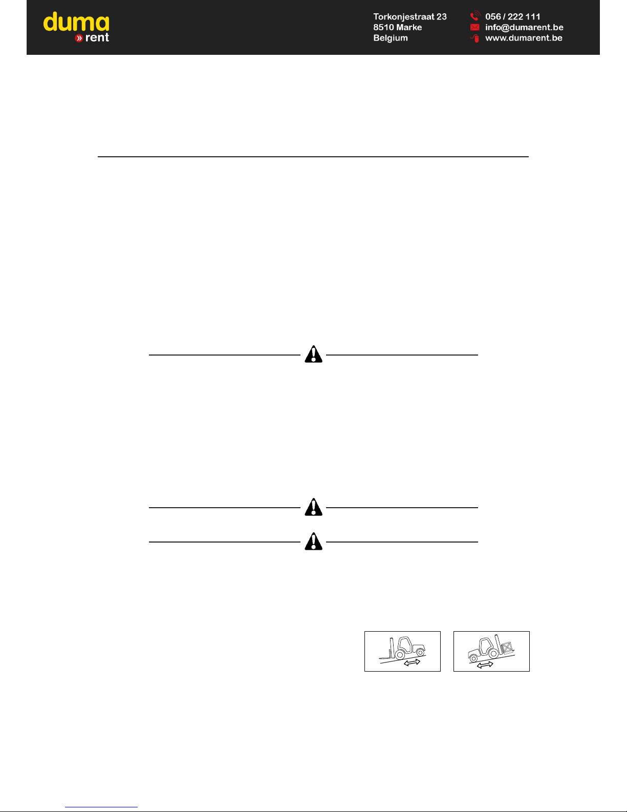
- Travelling on a longitudinal slope :
• Drive and brake gently.
• Moving without load : Forks or attachment facing downhill.
• Moving with load : Forks or attachment facing uphill.
- Ensure that scaffolding, loading platform or pile is capable of bearing
the weight.
- Ensure the stability and solidity of the ground before depositing a load.
1 - 12
Page 19

1 - 13
D - HANDLING
- Always consider safety and only transport balanced and correctly secured loads to avoid any risk of tipping.
- Fully engage forks under the load and move it in the transport position (The forks 300 mm from the ground and the
mast sloping backwards).
- For obvious reasons regarding the lift truck’s stability and clear visibility of the surrounding environment, only move the
lift truck when the mast is in the transport position.
- Do not manoeuvre the lift truck with the mast in the raised position unless under exceptional circumstances and then
with extreme caution, at very low speed and using gentle braking. Ensure that visibility is adequate and get another
person to guide you along if necessary.
- Never shift the position of the load while the lift truck is in motion.
- The simultaneous use of two lift trucks to handle heavy or bulky loads is a dangerous manoeuvre, requiring specific
precautions to be taken. This should only be done in exceptional circumstances and in the presence of a handling
manager.
- Never drive too fast or brake abruptly when carrying a load.
- During handling, drive at low speed.
- Check the load, particularly when turning corners and especially if it is very bulky.
- Secure unstable loads.
- Handle loads with caution, at slow speed, without sudden jerks when moving them at significant heights and jib
extention.
In the event of high winds or storms, do not carry out handling work that jeopardizes the stability of the lift truck and its
load, particularly if the load catches the wind badly.
- Do not change direction sharply and at high speed.
In the event of the lift truck overturning, do not try to leave the cabin during the incident.
YOUR BEST PROTECTION IS TO STAY FASTENED IN THE CABIN.
- Apply the parking brake when lifting or depositing a difficult load or when on an incline.
- Do not stop the lift truck with the load in an elevated position.
- Do not leave a laden lift truck with the parking brake applied on an incline which exceeds 15 %.
E - VISIBILITY
- Constantly keep clear visibility of the road, either direct view (looking backwards when reversing) or indirect view using
the panoramic rear view mirrors to check for people, animals, holes, obstacles, change of slope, etc.
- If the visibility in forward motion is not sufficient because of the bulkiness of the load, drive in reverse motion. This
manoeuvre must remain exceptional and for short distances.
- Ensure you have good visibility (Clean windows, adequate lighting, correctly adjusted rear view mirror, etc.).
- Signalling and lighting on the lift truck must take account of the conditions of use. In addition to series equipment
mounted on your lift truck, a certain number of options are available, such as : road lighting, stop lights, flashing light,
reverse lights, reverse buzzer alarm, front light, rear light, etc. Consult your agent or dealer.
IF NECESSARY, CONSULT YOUR DEALER.
Page 20
1 - 14
LOAD HANDLING
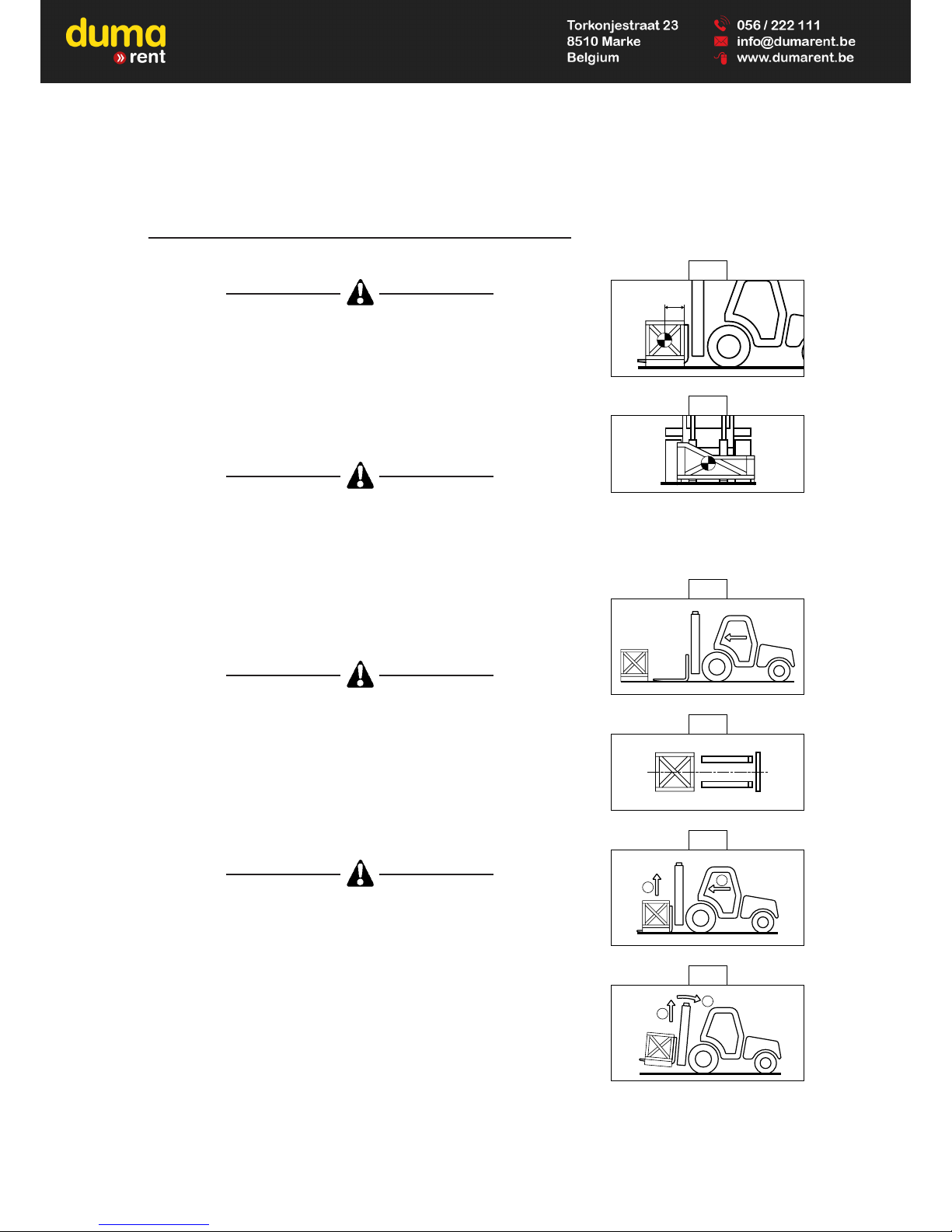
A - WEIGHT OF LOAD AND CENTRE OF GRAVITY
Carrying a load greater than the rated capacity for the lift truck or for the
attachment is prohibited.
- Before taking up a load, you must know its weight and its centre of gravity.
- The load chart relating to your lift truck is valid for a weight with its centre of
gravity 500 or 600 mm from the heel of the forks (As model of lift truck) (Fig.
A). For a higher centre of gravity, consult your agent or dealer.
- For irregular loads, determine the centre of gravity in the transverse
direction before handling (Fig. B).
For loads with a moving centre of gravity (e.g. liquids), take account of the
variations in the centre of gravity in order to determine the load to be hand-
led (Consult your agent or dealer) and be vigilant and take extra care to limit
these variations as far as possible.
B - TAKING UP A LOAD ON THE GROUND
- Approach the lift truck perpendicular to the load, with the forks in a
horizontal position (Fig. C).
- Adjust the fork spread and centering in connection with the load (Fig. D)
(Optional solutions exist, consult your dealer).
Beware of the risks of trapping or squashing limbs when manually adjusting
the forks. Always maintain an equal distance between the forks and the
centre of the carriage in order to keep the load completely stable.
- Move the lift truck forward slowly (1) and bring the forks to stop in front of
the load (Fig. E), if necessary, slightly lift the mast (2) while taking up the
load.
- Apply the parking brake and place the forward/reverse lever in neutral.
- Slightly lift the load (1), incline the mast (2) backwards in the transport
position (Fig. F).
Tilt the load sufficiently backwards to ensure its stability (loss of load on bra-
king) without upsetting the balance of the load in so doing.
500 mm
A
B
C
D
1
2
E
2
1
F
Page 21
1 - 15
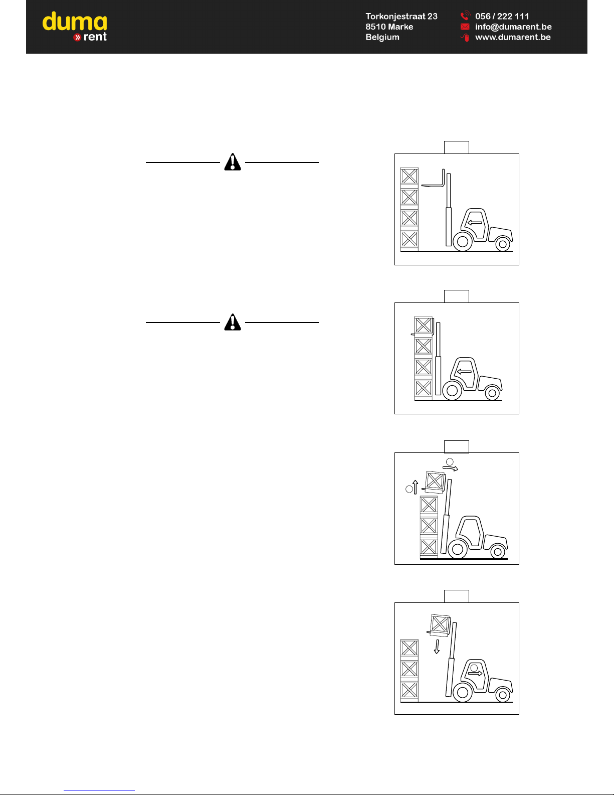
C - TAKING UP A HIGH LOAD ON TYRES
Under no circumstances should you pick up a load if the lift truck is not a
horizontal position. (See paragraph : F - HORIZONTAL POSITION OF THE
LIFT TRUCK in the chapter : LOAD HANDLING).
- Ensure that the forks will easily pass under the load.
- Approach the lift truck perpendicular to the load and with the forks in a
horizontal position (Fig. G) manoeuvring gently and carefully (See
paragraph : E - VISIBILITY in the chapter : HANDLING INSTRUCTIONS for
visibility of the road).
- Bring the forks to stop in front of the load (Fig. H). Apply the parking brake
and place the forward/reverse lever in neutral.
- Slightly lift the load (1) and incline the mast (2) backwards to stabilize the
load (Fig. I).
Tilt the load sufficiently backwards to ensure its stability (loss of load on bra-
king) without upsetting the balance of the load in so doing.
- Manoeuvring very gently and carefully (See paragraph : E - VISIBILITY in the
chapter : HANDLING INSTRUCTIONS for visibility of the road), back up the
lift truck (1) to release the load, and bring the load into the transport position
(Fig. J).
G
H
2
1
I
1
J
Page 22
1 - 16
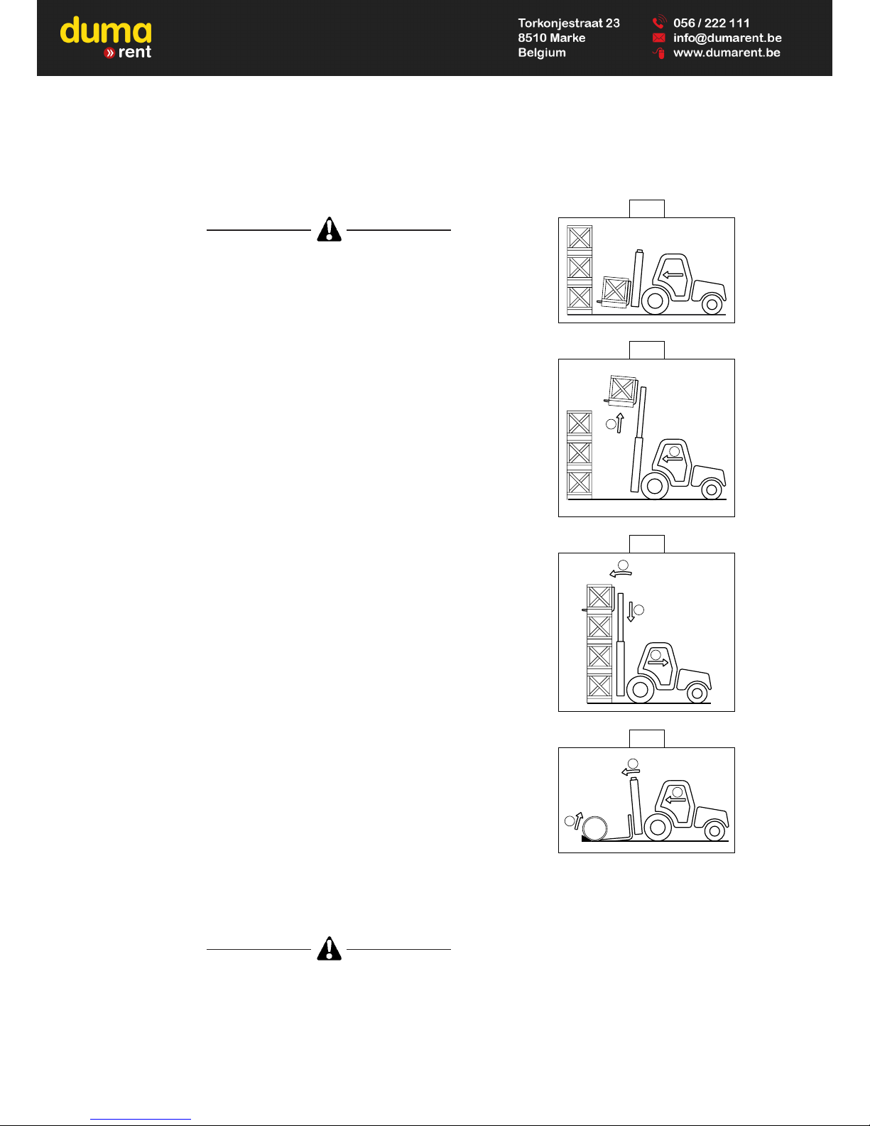
D - LAYING A HIGH LOAD ON TYRES
Under no circumstances should you lay down a load if the lift truck is not a
horizontal position. (See paragraph : F - HORIZONTAL POSITION OF THE
LIFT TRUCK in the chapter : LOAD HANDLING).
- Approach the load in the transport position in front of the pile (Fig. K).
- Lift the mast (1) until the load is above the pile, and move the lift truck
forward (2) (Fig. L) manoeuvring very gently and carefully (See paragraph :
E - VISIBILITY in the chapter : HANDLING INSTRUCTIONS for visibility of
the road). Apply the parking brake and place the forward/reverse lever in
neutral.
- Place the load in a horizontal position by tilting the mast forwards (1) and lay
it down on the pile (2) while checking the correct positioning of the load (Fig.
M).
- To drive very gently and carefully.
- Free the forks by reversing the lift truck (3) (Fig. M) (See paragraph : E VISIBILITY in the chapter : HANDLING INSTRUCTIONS for visibility of the
road). Then bring the forks into the transport position.
E - TAKING UP A NON PALLETISED LOAD
- Tilt the carriage (1) forwards and move the lift truck forward (2) while
simultaneously crowding the carriage backwards to slip the forks under the
load (Fig. N). If necessary, wedge the load.
F - HORIZONTAL POSITION OF THE LIFT TRUCK
Apart from the transverse slope of the ground, several parameters can upset
the horizontal position of the lift truck.
• The tyre pressure.
• The stability of the ground.
• The balance of the load.
• Strong wind or stormy conditions.
Before any handling work, check the points above and ensure that the lift
truck is completely horizontal.
2
1
3
N
3
2
1
M
1
2
L
K
Page 23

1 - 17
Page 24

1 - 18
MAINTENANCE INSTRUCTIONS
A - GENERAL
- Read the operator's manual carefully and ensure you understand it.
- Stop the I.C. engine, when an intervention is necessary.
- Wear clothes suitable for the maintenance of the lift truck, avoid wearing jewellery and loose clothes. Tie and protect
your hair, if necessary.
- Ensure the area is sufficiently ventilated before starting the lift truck.
Make sure that the disposal of process materials and of spare parts is carried out in total safety
and in a ecological way.
- Carry out all repairs immediately, even if the repairs concerned are minor.
- Repair all leaks immediately, even if the leak concerned is minor.
- Do not attempt to loosen unions, hoses or any hydraulic component with the circuit under pressure.
The handling and removal of the balancing valves or safety valves which may be fitted to the cylinders of your lift truck
can be dangerous. A balancing valve must only be removed when the cylinder concerned is at rest and the hydraulic
circuit is depressurised.
This operation can only be carried out by authorised staff.
- Do not smoke or approach the lift truck with a flame, when the fuel tank is open or is being filled.
- Take care not to burn yourself (Exhaust, radiator, I.C. engine, etc.).
- Disconnect the negative cable terminal (-) from the top of the battery before working on the electrical circuit or on the lift
truck (e.g. : Welding).
- Do not drop metallic items on the battery.
- When carrying out electric welding work on the lift truck, connect the negative cable from the equipment directly to the
part being welded, so as to avoid high tension current passing through the alternator.
B - MAINTENANCE
- The maintenance and the keeping in compliance of the lift truck are compulsory.
- Carry out daily maintenance (See chapter : A - DAILY OR EVERY 10 HOURS SERVICE in paragraph : 3 MAINTENANCE).
- Do not run the engine without air filter, or with oil, water or fuel leaks.
Wait for the I. C engine to cool before removing the radiator cap or expansion pan (Pressurised system).
- Change the filter cartridges (See servicing schedules in chapter : FILTERS CARTRIDGES AND BELTS in
paragraph : 3 - MAINTENANCE).
C - LEVELS
- Use the recommended lubricants (Never use contaminated lubricants).
- Do not fill the fuel tank when the I.C. engine is running.
- Only fill up the fuel tank in areas specified for this purpose.
- Do not fill the fuel tank to the maximum level.
MAINTENANCE INSTRUCTIONS OF THE LIFT TRUCK
Page 25

1 - 19
D - WASHING
- Clean the lift truck or at least the area concerned before any intervention.
- Remember to close the doors and the windows of the cab.
- During washing, avoid the articulations and electrical components and connections.
If necessary, protect against penetration of water, steam or cleaning agents, components susceptible of being dama-
ged, particularly electrical components and connections and the injection pump.
- Clean the lift truck of any fuel, oil or grease trace.
FOR ANY INTERVENTION OTHER THAN REGULAR MAINTENANCE, CONSULT YOUR DEALER.
Page 26

1 - 20
INTRODUCTION
- Our lift trucks have been designed for easy handling by the operator and maximum ease of maintenance for the
mechanic.
- However, before commencing to operate the lift truck, the user should carefully read and understand the various
chapters of this manual which has been provided to solve driving and maintenance problems. By following these
instructions the user will be able to take full advantage of the versatility of this lift truck.
- The operator must familiarize himself with the positions and functions of all the controls and instruments before
operating the lift truck.
Do not attempt to start a new lift truck before the following checks have been carried out :
LUBRICATION
- Check that all the correct grades of oils and greases that are required are available ; see chapter : SERVICING
SCHEDULE in paragraph : 3 - MAINTENANCE and top up if necessary.
For operation under average climatic conditions, i.e. : between -15 °C and + 35 °C, correct levels of lubricants in all the
circuits are checked in production. For operation under more severe climatic conditions, before starting up, it is necessa-
ry to drain all the circuits, then ensure correct levels of lubricants using lubricants properly suited to the relevant ambient
temperatures. It is the same for the cooling liquid (Contact your dealer for information, if necessary).
DRY AIR FILTER
- Ensure that the air filter is undamaged and not blocked.
- Tighten the fastening devices if necessary.
Never run the engine with the air filter removed or damaged.
COOLING SYSTEM
- Do not start the lift truck without checking the radiator coolant level or if the fan belt is damaged or broken.
HYDRAULIC SYSTEM
- Check by a visual examination that there are no leaks or oil oozing in the hoses, connections and unions. If necessary,
tighten or repair the defective connections.
- Also check that the tank oil level is correct.
BRAKING SYSTEM
- Check by a visual examination that there are no leaks or oil oozing in the hoses, connections and unions. If necessary,
tighten or repair the defective connections.
- Also check the oil level in the tank.
Ensure that the recommended oil is used, in order to avoid serious damage to the braking system.
TYRES
- Make sure that the wheel nuts are correctly tightened (See chapter : A - DAILY OR EVERY 10 HOURS SERVICE in
paragraph : 3 - MAINTENANCE) and that the tyre pressures are correct (See chapter : CHARACTERISTICS in
paragraph : 2 - DESCRIPTION).
FUEL SYSTEM
- Check that all fuel lines are secured.
- If necessary drain the fuel filter and bleed the fuel system of air.
BEFORE STARTING UP A NEW LIFT TRUCK
Page 27

1 - 21
ELECTRICAL CIRCUIT
- Check the level and the density of the electrolyte in the battery (See chapter : B - EVERY 50 HOURS SERVICE in
paragraph : 3 - MAINTENANCE).
- Check the components of the electrical system, the connections and fastening devices.
IF NECESSARY, CONSULT YOUR DEALER.
Page 28

1 - 22
Page 29

2 - 1
2 - DESCRIPTION
2 - DESCRIPTION
Page 30

2 - 2
Page 31

2 - 3
Page 32

2 - 4
IDENTIFICATION OF THE LIFT TRUCK
D
As our policy is to promote a constant improvement of our products, our
range of telescopic lift trucks may undergo certain modifications, without
obligation for us to advise our customers.
When you order parts, or when you require any technical information, always
specify :
NOTE : For the owner's convenience, it is recommended that a note of these
numbers is made in the spaces provided, at the time of the delivery of
the lift truck.
PLATE MANUFACTURER OF THE LIFT TRUCK (FIG. A)
- Model
- Series
- Serial Nr
- Chassis Nr
- Year of manufacture
I.C. ENGINE (FIG. B)
- Engine Nr
HYDROSTATIC PUMP (FIG. C)
- Pump Nr
- Codification type
- Manufacturer’s Nr
- Year of manufacture
HYDROSTATIC MOTOR (FIG. D)
- Pump Nr
- Codification type
- Manufacturer’s Nr
- Year of manufacture
A
B
C
Page 33

2 - 5
TRANSFER BOX-FRONT (FIG. E)
- Type
- MANITOU reference
CAB (FIG. F)
- Type
- Serial Nr
MAST (FIG. G)
- Mast identification Nr
PLATE MANUFACTURER OF THE ATTACHMENT (FIG. H)
- Model
- Serial Nr
- Year of manufacture
E
F
G
MANITOU BF
44158 ANCENIS CEDEX
FRANCE
TELEX : 710 521
FAX : 40.83.36.88
MODELE
N° dans la série
Année fabrication
Masse à vide
C d G / Tablier
A vide / En charge : mm
/
kg
250 bar maxi.
Cap. Nominale
Pression de service
AVERTISSEMENT : RESPECTEZ
LA CAPACITE DE L'ENSEMBLE
"CHARIOT ET EQUIPEMENT"
N°207701
H
Page 34

2 - 6
PERKINS 1004-4
4
4
Direct
1.3.4.2
0,20 mm
0,45 mm
3990 cm
3
100 mm
127 mm
16.5 : 1
2300 tr/mn
850 tr/mn
2500 tr/mn
82 cv 60,5 kw
80,5 cv 59,3 kw
85,2 cv 62,9 kw
82,1 cv 60,5 kw
289 Nm to 1425 rpm
dry 3 microns
By water
Puller
6
457 mm
77 °C to 85 °C
92 °C to 98 °C
Negative
12 V - 105 Ah
14 V - 35 A (1stAssembly)
12 V - 55 A (2ndAssembly)
Incorporated into the alternator
12 V - 2,2 kw
A4VG56DA With variable cubic capacity and
with automatic power governor.
Electromagnetic 12V.
Hydraulic by valve TH7
56 cm
3
0 cm
3
141,68 L/min
ENGINE
- Type
- Number of cylinders
- Number of strokes
- Injection system
- Ignition sequence
- Clearance of rocker valve (Cold)
. Inlet
. Exhaust
- Capacity
- Bore
- Stroke
- Volumetric ratio
- Nominal running speed
- Idle speed
- Full speed
- Power DIN 70.020
- Power DIN 6270 B
- Power SAE
- Power BS.AU 141 a 1971
- Maximum torque
- Air cleaner
COOLING CIRCUIT
- Type
- Fan
. Number of blades
. Diameter
- Thermostat
. Start opening
. Full opening
ELECTRIC CIRCUIT
- Earth
- Battery
- Alternator
- Tension regulator
- Starter
HYDROSTATIC TRANSMISSION
HYDROSTATIC PUMP
- Type
- Gear reverser
- Inching control
- Main pump
. Capacity MAXI
. Capacity MINI
. MAX. flow rate
CHARACTERISTICS
UP TO MACHINE N° 142 126
Page 35

2 - 7
420 Bar
380 Bar
11,1 cm
3
27,19 L/min.
25 Bar (Transmission in neutral).
A6VM107DA variable displacement
107 cm3
26 cm3
HURTH Coupled with front axle.
1
1
HURTH
Epicyclic
Foot pedal. Mechanical
Multidisc brake immersed in oil.
Foot pedal. Hydraulic brake acting on front
wheels.
Mechanical hand lever applied on the front
wheels.
. Working pressure
(Up to pump N° : 3890010)
(From pump N° : 3890011)
- Boost pump
. Cubic capacity
. MAX. flow rate
. Boost pressure MAX. r.p.m.
HYDROSTATIC MOTOR
- Type
. Capacity MAXI
. Capacity MINI
TRANSFER BOX
- Type
- Number of forward speeds
- Number of reverse speeds
FRONT AXLE
- Type
- Hub reducers
- Differential lock
BRAKE
- Type
- Service brake
- Parking brake
Page 36

2 - 8
PERKINS 1004-42 AR 81155
4
4
Direct
1.3.4.2
0,20 mm
0,45 mm
4233 cm
3
103 mm
127 mm
18.5 / 1
2300 tr/mn
825 tr/mn
2500 tr/mn
83 cv 61,5 kw
85 cv 63 kw
89 cv 65,5 kw
298 Nm to 1400 tr/mn
300 Nm to 1400 tr/mn
dry 3 microns
By water
Puller
6
457 mm
77° C to 85° C
92° C to 98° C
Negative
12 V - 105 Ah - 680 A EN
12 V - 65 A
Magneti Marelli A127
Incorporated into the alternator
12 V
Magneti Marelli M127
A4VG56DA With variable cubic capacity and
with automatic power governor.
Electromagnetic 12V.
Hydraulic by valve TH7
56 cm
3
0 cm
3
141,68 L/mn
380 Bar
ENGINE
- Type
- Number of cylinders
- Number of strokes
- Injection system
- Ignition sequence
- Rocker arm clearance (Hot)
. Inlet
. Exhaust
- Capacity
- Bore
- Stroke
- Volumetric ratio
- Nominal running speed
- Idle speed
- Full speed
- Power ISO 3046-1
- Power ISO/TR 14396
- Power SAE
- Maximum torque ISO 3046-1
- Maximum torque ISO/TR 14396
- Air cleaner
COOLING CIRCUIT
- Type
- Fan
. Number of blades
. Diameter
- Thermostat
. Start opening
. Full opening
ELECTRIC CIRCUIT
- Earth
- Battery
- Alternator
. Type
. Tension regulator
- Starter
. Type
HYDROSTATIC TRANSMISSION
HYDROSTATIC PUMP
- Type
- Gear reverser
- Inching control
- Main pump
. Capacity MAXI
. Capacity MINI
. MAX. flow rate
. Working pressure
FROM MACHINE N° 142 127
Page 37

2 - 9
11,1 cm
3
27,19 L/min.
25 Bar (Transmission in neutral).
A6VM107DA variable displacement
107 cm3
26 cm3
HURTH Coupled with front axle.
1
1
HURTH
Epicyclic
Foot pedal. Mechanical
Multidisc brake immersed in oil.
Foot pedal. Hydraulic brake acting on front
wheels.
Mechanical hand lever applied on the front
wheels.
- Boost pump
. Cubic capacity
. MAX. flow rate
. Boost pressure MAX. r.p.m.
HYDROSTATIC MOTOR
- Type
. Capacity MAXI
. Capacity MINI
TRANSFER BOX
- Type
- Number of forward speeds
- Number of reverse speeds
FRONT AXLE
- Type
- Hub reducers
- Differential lock
BRAKE
- Type
- Service brake
- Parking brake
Page 38

2 - 10
FRONT TYRES
STANDARD
OPTION
REAR TYRES
STANDARD
OPTION
HYDRAULIC CIRCUIT
UP TO MACHINE N° : 109 832 EXCEPT FOR N° : 107 781
- Lifting, tilting, attachment circuit
. Type of pump
. Flow rate at full speed
. Pressure
. Capacity
- Steering direction
. Type of pump
. Flow rate at full speed
. Pressure
. Capacity
- Filtration
. Return
- Hydraulic shock absorber
. Capacities
. Pressure
Gear pump
71,3 L/min.
200 Bar
31 cm
3
Gear pump
27,6 L/min.
140 Bar
12 cm
3
10 Microns
1,4 L
120 Bar
MSI 40
DIMENSIONS PRESSURE
TYRE LOAD
PRESSURE ON THE CONTACT SURFACE
AERA OF THE CONTACT SURFACE
UNLADEN LOADED UNLADEN LOADED UNLADEN LOADED
315/70 R22,5 G391 6,75 Bar
2000 Kg 5200 Kg 6,7 Kg/cm26,7 Kg/cm2300 cm
2
780 cm
2
GOOD YEAR
DIMENSIONS PRESSURE
TYRE LOAD
PRESSURE ON THE CONTACT SURFACE
AERA OF THE CONTACT SURFACE
UNLADEN LOADED UNLADEN LOADED UNLADEN LOADED
225/75 R15 XZM 149 A5 5 Bar
1850 Kg 650 Kg 5,4 Kg/cm23,1 Kg/cm2345 cm
2
210 cm
2
MICHELIN
DIMENSIONS PRESSURE
TYRE LOAD
PRESSURE ON THE CONTACT SURFACE
AERA OF THE CONTACT SURFACE
UNLADEN LOADED UNLADEN LOADED UNLADEN LOADED
PPS 28-9x15 CSESC10
1850 Kg 650 Kg 7,2 Kg/cm24,4 Kg/cm2260 cm
2
150 cm
2
CONTINENTAL (Solid)
DIMENSIONS PRESSURE
TYRE LOAD
PRESSURE ON THE CONTACT SURFACE
AERA OF THE CONTACT SURFACE
UNLADEN LOADED UNLADEN LOADED UNLADEN LOADED
12-5 R20 16PR MPT80 5 Bar
2000 Kg 5200 Kg 3,6 Kg/cm24,2 Kg/cm2560 cm
2
1250 cm
2
CONTINENTAL
445/65 R19,5 Tubeless XZY 165K 6,3 Bar
2000 Kg 5200 Kg 4,3 Kg/cm25,7 Kg/cm2470 cm
2
905 cm
2
MICHELIN
16/70-20 14PR E91-2 4,5 Bar
2000 Kg 5200 Kg 7,2 Kg/cm28,8 Kg/cm2280 cm
2
595 cm
2
DUNLOP
10.00-20 CSE SC10
2000 Kg 5200 Kg 5,5 Kg/cm28,4 Kg/cm2365 cm
2
620 cm
2
CONTINENTAL (Solid)
Page 39

2 - 11
Gear pump
37 cm
3
85,1 L/mn
200 Bar
Load control system
140 Bar
10 Microns
100 Microns
1,4 L
120 Bar
Gear pump
37 cm
3
92,5 L/mn
200 Bar
Load control system
145 Bar
10 Microns
100 Microns
1,4 L
120 Bar
80,5 dBA
24 km/h
24 km/h
3700 mm (DUPLEX mast)
4000 kg
500 mm
100 kg
HYDRAULIC CIRCUIT
UP TO MACHINE N° : 109 833 AND FOR N° : 107 781
UP TO MACHINE N° 130 517
- Type of pump
. Capacity
- Lifting, tilting, attachment circuit
. Flow rate at full speed
. Pressure
- Steering direction
. Flow rate at full speed
. Pressure
- Filtration
. Return
. Suction (Up to machine N° : 115 593)
- Hydraulic shock absorber
. Capacities
. Pressure
HYDRAULIC CIRCUIT
FROM MACHINE N° 130 518
- Type of pump
. Capacity
- Lifting, tilting, attachment circuit
. Flow rate at full speed
. Pressure
- Steering direction
. Flow rate at full speed
. Pressure
- Filtration
. Return
. Suction
- Hydraulic shock absorber
. Capacities
. Pressure
SPECIFICATIONS
- Level of sound pressure in the driver's cabin
(According to norm prEN 12053 : 1995)
. Cab model
- Travel speed of the lift truck
. Forward unladen
. Reverse unladen
- Standard lift height
- Rated capacity with standard mast
- Load center
- Weight of forks (Each)
Page 40

2 - 12
0,525 m/s
0,518 m/s
0,424 m/s
0,542 m/s
6975 kg
10975 kg
3425 kg
9740 kg
3550 kg
1235 kg
2050 daN
3600 daN
26 % to 1 km/h
30 % to 1 km/h
daN
- Lifting movement (With standard mast)
. Unladen lifting
. Rated load lifting
. Unladen lowering
. Rated load lowering
- Weight of lift truck with standard mast
. Unladen
. Rated load
- Weight per axle with standard mast (Transport position)
. Front unladen
rated load
. Rear unladen
rated load
- Drawbar pull
. Unladen
. Rated load
- Maximum ramp negotiable in forward motion
. Unladen
. Rated load
- Break out force at bucket teeth
Page 41

2 - 13
FRONT TYRES
STANDARD
OPTION
REAR TYRES
STANDARD
OPTION
HYDRAULIC CIRCUIT
UP TO MACHINE N° : 109 832 EXCEPT FOR N° : 107 781
- Lifting, tilting, attachment circuit
. Type of pump
. Flow rate at full speed
. Pressure
. Capacity
- Steering direction
. Type of pump
. Flow rate at full speed
. Pressure
. Capacity
- Filtration
. Return
- Hydraulic shock absorber
. Capacities
. Pressure
Gear pump
71,3 L/mn
210 Bar
31 cm
3
Gear pump
27,6 L/mn
140 Bar
12 cm
3
10 Microns
1,4 L
120 Bar
MSI 50
DIMENSIONS PRESSURE
TYRE LOAD
PRESSURE ON THE CONTACT SURFACE
AERA OF THE CONTACT SURFACE
UNLADEN LOADED UNLADEN LOADED UNLADEN LOADED
315/70 R22,5 G391 7,75 Bar
2050 Kg 6000 Kg 7,6 Kg/cm27,6 Kg/cm2270 cm
2
790 cm
2
GOOD YEAR
DIMENSIONS PRESSURE
TYRE LOAD
PRESSURE ON THE CONTACT SURFACE
AERA OF THE CONTACT SURFACE
UNLADEN LOADED UNLADEN LOADED UNLADEN LOADED
225/75 R15 XZM 149 A5 6 Bar
2300 Kg 800 Kg 6,3 Kg/cm23,8 Kg/cm2370 cm
2
210 cm
2
MICHELIN
DIMENSIONS PRESSURE
TYRE LOAD
PRESSURE ON THE CONTACT SURFACE
AERA OF THE CONTACT SURFACE
UNLADEN LOADED UNLADEN LOADED UNLADEN LOADED
PPS 28-9x15 CSE SC10
2300 Kg 800 Kg 8 Kg/cm24,7 Kg/cm2290 cm
2
170 cm
2
CONTINENTAL (Solid)
DIMENSIONS PRESSURE
TYRE LOAD
PRESSURE ON THE CONTACT SURFACE
AERA OF THE CONTACT SURFACE
UNLADEN LOADED UNLADEN LOADED UNLADEN LOADED
12-5 R20 22PR MPT80 7 Bar
2050 Kg 6000 Kg 4,1 Kg/cm25 Kg/cm
2
500 cm
2
1210 cm
2
CONTINENTAL
445/65 R19,5 Tubeless XZY 165K 7,5 Bar
2050 Kg 6000 Kg 4,8 Kg/cm26,7 Kg/cm2430 cm
2
895 cm
2
MICHELIN
16/70-20 14PR E91-2 5,5 Bar
2050 Kg 6000 Kg 7,1 Kg/cm29,5 Kg/cm2290 cm
2
635 cm
2
DUNLOP
10.00-20 CSE SC10
2050 Kg 6000 Kg 5,6 Kg/cm29,5 Kg/cm2370 cm
2
635 cm
2
CONTINENTAL (Solid)
Page 42

2 - 14
Gear pump
37 cm
3
85,1 L/mn
200 Bar
Load control system
140 Bar
10 Microns
100 Microns
1,4 L
120 Bar
Gear pump
37 cm
3
92,5 L/mn
200 Bar
Load control system
145 Bar
10 Microns
100 Microns
1,4 L
120 Bar
80,5 dBA
24 km/h
24 km/h
3700 mm (DUPLEX mast)
5000 kg
600 mm
130 kg
HYDRAULIC CIRCUIT
FROM MACHINE N° : 109 833 AND FOR N° : 107 781
UP TO MACHINE N° 130 517
- Type of pump
. Capacity
- Lifting, tilting, attachment circuit
. Flow rate at full speed
. Pressure
- Steering direction
. Flow rate at full speed
. Pressure
- Filtration
. Return
. Suction (From machine N° : 115 593)
- Hydraulic shock absorber
. Capacities
. Pressure
HYDRAULIC CIRCUIT
FROM MACHINE N° 130 518
- Type of pump
. Capacity
- Lifting, tilting, attachment circuit
. Flow rate at full speed
. Pressure
- Steering direction
. Flow rate at full speed
. Pressure
- Filtration
. Return
. Suction
- Hydraulic shock absorber
. Capacities
. Pressure
SPECIFICATIONS
- Level of sound pressure in the driver's cabin
(According to norm prEN 12053 : 1995)
. Cab model
- Travel speed of the lift truck
. Forward unladen
. Reverse unladen
- Standard lift height
- Rated capacity with standard mast
- Load center
- Weight of forks (Each)
Page 43

2 - 15
0,451 m/s
0,435 m/s
0,348 m/s
0,451 m/s
7900 kg
12900 kg
3450 kg
11345 kg
4450 kg
1555 kg
2050 daN
3600 daN
24 % to 1 km/h
25 % to 1 km/h
daN
- Lifting movement (With standard mast)
. Unladen lifting
. Rated load lifting
. Unladen lowering
. Rated load lowering
- Weight of lift truck with standard mast
. Unladen
. Rated load
- Weight per axle with standard mast (Transport position)
. Front unladen
rated load
. Rear unladen
rated load
- Drawbar pull
. Unladen
. Rated load
- Maximum ramp negotiable in forward motion
. Unladen
. Rated load
- Break out force at bucket teeth
Page 44

2 - 16
MAST CHARACTERISTICS
DOUBLE MAST WITH ALL-ROUND VISION
MSI 40 MSI 50
MAST HL Z Y LL H H1 H2 HL Z Y LL H H1 H2
3m00 3050 10° 12° – 2425 3977 54 3060 10° 12° – 2425 3972 44
3m30 3350 10° 12° – 2575 4277 54 3360 10° 12° – 2575 4272 44
3m50 3550 10° 12° – 2675 4477 54 3560 10° 12° – 2675 4472 44
3m70 3750 10° 12° – 2775 4677 54 3760 10° 12° – 2775 4672 44
4m00 4050 10° 12° – 2925 4977 54 4060 10° 12° – 2925 4972 44
4m50 4550 10° 12° – 3175 5477 54 4560 10° 12° – 3175 5472 44
5m00 5050 10° 12° – 3425 5977 54 5060 10° 12° – 3425 5972 44
TRIPLE MAST WITH TOTAL FREE-ACTING LIFT
MSI 40 MSI 50
MAST HL Z Y LL H H1 H2 HL Z Y LL H H1 H2
3m70 3750 10° 12° 1258 2175 4667 44 3760 10° 12° 1263 2175 4672 44
4m00 4050 10° 12° 1358 2275 4967 44 4060 10° 12° 1363 2275 4972 44
4m30 4350 10° 12° 1458 2375 5267 44 4360 10° 12° 1463 2375 5272 44
4m50 4550 10° 12° 1533 2450 5467 19 4560 10° 12° 1538 2450 5472 19
4m70 4750 10° 12° 1593 2510 5667 39 4760 10° 12° 1598 2510 5672 39
5m00 5050 10° 12° 1708 2625 5967 14 5060 10° 12° 1713 2625 5972 14
5m50 5550 10° 12° 1858 2775 6467 44 5560 10° 12° 1863 2775 6472 44
6m00 6050 10° 12° 2033 2950 6967 19 6060 10° 12° 2038 2950 6972 19
DOUBLE MAST WITH TOTAL FREE-ACTING LIFT
MSI 40 MSI 50
MAST HL Z Y LL H H1 H2 HL Z Y LL H H1 H2
3m00 3050 10° 12° 1532 2450 3968 32 3060 10° 12° 1541 2450 3969 32
3m30 3350 10° 12° 1682 2600 4268 32 3360 10° 12° 1691 2600 4269 32
3m50 3550 10° 12° 1782 2700 4468 32 3560 10° 12° 1791 2700 4469 32
3m70 3750 10° 12° 1882 2800 4668 32 3760 10° 12° 1891 2800 4669 32
4m00 4050 10° 12° 2032 2950 4968 32 4060 10° 12° 2041 2950 4969 32
HL : Lift height in mm
Z : Forward tilting
Y : Backward tilting
LL : Free-acting lift in mm
H : Overall height with folded mast in mm
H1 : Overall height with spreaded out mast in mm
H2 : Carriage overshooting
Page 45

2 - 17
Page 46

2 - 18
DIMENSIONS AND LOAD CHART
MSI 40 MSI 50
Page 47

2 - 19
MSI 40 MSI 50
A 1200 mm 1200 mm
B 2075 mm 2075 mm
C 692 mm 702 mm
D 3312 mm 3322 mm
E 4512 mm 4522 mm
F 1391 mm 1391 mm
F1 1135 mm 1135 mm
G 185 mm 185 mm
G1 220 mm 220 mm
G2 225 mm 225 mm
G3 210 mm 210 mm
H 2775 mm 2775 mm
H* 2575 mm 2575 mm
H1 4677 mm 4672 mm
H1* 4277 mm 4272 mm
I 545 mm 545 mm
J 1300 mm 1300 mm
K 1670 mm 1670 mm
L 50 mm 60 mm
N 1710 to 1775 mm 1710 to 1775 mm
O 150 mm 150 mm
P1 30 ° 58 % 30 ° 58 %
P2 27 ° 51 % 27 ° 51 %
P3 58 ° 160 % 58 ° 160 %
R 2700 mm 2700 mm
S 2760 mm 2760 mm
T 4992 mm 5002 mm
U 2370 mm 2370 mm
V 2900 mm 2900 mm
V1 200 mm 200 mm
W 1735 mm 1735 mm
Y 12 ° 12 °
Z 10 ° 10 °
H - H1 = Standard mast DUPLEX 3M70
H* - H1* = Option mast DUPLEX 3M30
Page 48

2 - 20
INSTRUMENTS AND CONTROLS
UP TO MACHINE N° : 117 315
1
2
3
4
5
6
7
8
9
10
11
12
13
13
13
14
15
19
20
20
21
21
22
22
17
23
23
24
24
25
16
18
28
26
27
30
Page 49

2 - 21
DESCRIPTION
1 - DRIVER’S SEAT
2 - TILTING HANDLE OF WHEEL
3 - INSTRUMENT PANEL
4 - SWITCH'S AND LAMP'S PANEL
5 - LIGHT SWITCH , HORN AND INDICATOR SWITCH
6 - IGNITION SWITCH
7 - FUSES BOX
8 - ACCELERATOR PEDAL
9 - INCHING AND SERVICE BRAKE PEDAL
10 - DIFFERENTIAL LOCK PEDAL
11 - FORWARD/REVERSE LEVER
12 - PARKING BRAKE LEVER
13 - HYDRAULIC CONTROL DISTRIBUTOR LEVERS
14 - BRAKING OIL TANK SLUDGE DOOR
15 - ENGINE SLUDGE DOOR
LIFTING CAB
16 - UNLOCKING HANDLE FOR CAB
17 - LIFTING CAB SWITCH (OPTION)
18 - SAFETY SHORE FOR LIFTING CAB
19 - CAB HEATER CONTROL
20 - HEATING VENTILATORS
21 - DOOR LOCKS
22 - CLOSING HANDLES FOR DOOR
23 - UNLOCKING HANDLES FOR OPEN DOOR
24 - ACCES HANDLES DRIVER'S CAB
25 - HANDLES FOR L.H. SIDE WINDOW OPENING
26 -OUTSIDE REARVIEW MIRROR
27 - WINDSCREEN WASHER TANK
28 - ROOF LIGHT
29 - TOWING PIN
30 - DOCUMENT HOLDER NET
31 - REAR LIGHTS AND INDICATORS
NOTA : All the terms such as : RIGHT, LEFT, FRONT, REAR are meant for an observer seated on driver's seat and
looking in front of him.
Page 50

2 - 222 - 22
1 - DRIVER’S SEAT
1stASSEMBLY
FOR OPTIMAL COMFORT, THIS SEAT CAN BE ADJUSTED IN
DIFFERENT WAYS.
LONGITUDINAL ADJUSTMENT
- Pull the locking lever 1 upwards.
- Slide the seat to the required position.
- Release the lever and ensure it returns to the lock position.
SEAT SUSPENSION ADJUSTMENT
- Refer to the seat's graduation.
- Turn handle 2 depending on the driver's weight.
2ndASSEMBLY
FOR OPTIMAL COMFORT, THIS SEAT CAN BE ADJUSTED IN
DIFFERENT WAYS.
LONGITUDINAL ADJUSTMENT
- Pull the locking lever 1 upwards.
- Slide the seat to the required position.
- Release the lever and ensure it returns to the lock position.
SEAT SUSPENSION ADJUSTMENT
- Pull and lift up the locking lever 2 so as to place it into one of these five
positions.
Position A : Light-weight driver (50 kg).
Position B : Intermediate.
Position C : Middle-weight driver.
Position D : Intermediate.
Position E : Heavy-weight driver (120 kg).
ANGLE ADJUSTMENT OF THE BACK-REST
- Pull the locking lever 3 backwards.
- Tilt the back-rest into one of the three possible positions.
- Release the locking lever and ensure it returns to the lock position.
ANGLE ADJUSTMENT OF THE WHOLE SEAT
- Lift up the locking lever 4.
- Tilt the seat forwards or backwards.
- Release the lever and ensure it returns to the lock position.
2 - TILTING HANDLE OF WHEEL
- Turn the lever 1 towards A for loosening.
- Tilt the steering wheel into the required position.
- Turn the lever 1 towards B for blocking.
2
1
1
1
2
3
4
A
B
C
D
E
A
B
Page 51

2 - 23
3 - INSTUMENT PANEL
A - Fuel level gauge.
B - Hourmeter.
C - Water temperature gauge.
D - Green indicator lamp.
E - Red engine oil pressure lamp.
F - Red alternator charge lamp.
G - Blue main beam lamp.
H - Red air filter clog lamp.
I - Red hydrostatic transmission oil filter clog lamp.
J - Fuses box.
A - FUEL LEVEL GAUGE
B - HOURMETER
It shows the number of hours the fork lift truck has run. The hours are shown on the dial up to a multiple of thousand.
The moving tell-tale shows the good working order of the apparatus.
C - WATER TEMPERATURE GAUGE
When the truck works in normal conditions the needle of the indicator should indicate 80° to 90° C.
If the needle indicates an abnormally high temperature (100° C maximum) , stop the engine immediately and investigate
the cooling system for the cause of the malfunction.
D - GREEN INDICATOR LAMP
It is illuminated when the indicators are on and indicates that they are functioning properly.
E - RED ENGINE OIL PRESSURE LAMP
This lamp is illuminated when the ignition switch is in the ON position and should go out as soon as the fork lift truck
starts. If this lamp stays on when the engine is running, stop the fork lift truck immediately and look for the cause (see oil
level in engine crankcase).
F - RED ALTERNATOR CHARGE LAMP
This lamp is illuminated when the ignition switch is in the ON position and should go out as soon as the fork lift truck
starts. If this lamp stays on when the engine is running, stop the fork lift truck immediately and check the electrical circuit
as well as the alternator belt.
G - BLUE MAIN BEAM LAMP (OPTION)
The lamp is illuminated when lights are on main beam.
H - RED AIR FILTER CLOG LAMP
This lamp provides the operator with information about the condition of the filter cartridge. If this cartridge is clogged the
lamp comes on (See cleaning and replacement requirements in chapter : FILTERS CARTRIDGES AND BELTS in
paragraph : 3 - MAINTENANCE).
I - RED HYDROSTATIC TRANSMISSION OIL FILTER CLOG LAMP
This lamp provides the operator with information about the condition of the filter cartridge. If this cartridge is clogged the
lamp comes on (See cleaning and replacement requirements in chapter : FILTERS CARTRIDGES AND BELTS in
paragraph : 3 - MAINTENANCE).
NOTE : This lamp comes on by cold weather or when starting the fork lift truck, it goes off when the hydraulic oil reach
the temperature of functionning.
Page 52

2 - 24
J - FUSES BOX
Remove the cover to replace a fuse.The using is described herewith from L.H. to R.H. :
1 : fuse hand the left : Indicators (7,5A).
2 : Horn. + Stop swith (7,5A).
3 : OPTION R.H sidelight. + R.H rear light (7,5A).
4 : OPTION L.H sidelight + L.H rear light (7,5A).
5 : OPTION Dipped headlights (7,5A).
6 : Forward / Reverse (7,5A).
7 : Heating.+ 2nd heating OPTION (7,5A).
8 : Front windscreen wiper and windscreen washer + Brake oil level lamp (7,5A).
9 : OPTION Warning light (7,5A).
10 : OPTION (7,5A).
11 : OPTION (7,5A).
12 : OPTION Main beam (7,5A).
NOTE : Replace a used fuse with a new fuse of the same quality and capacity. Never reuse a repaired fuse.
4 - SWITCH'S AND LAMP'S PANEL
A - Front windscreen wiper switch and windscreen washer.
B - OPTION heater fan switch.
C - R ear windscreen washer switch.
E - OPTION warning light switch.
D - Brake oil level lamp.
F - OPTION working head light switch.
or
OPTION left working head light switch.
G - OPTION flashing alarm light switch.
H - OPTION working tail light switch.
or
OPTION left working tail light switch.
A - FRONT WINDSCREEN WIPER SWITCH AND WINDSCREEN WASHER
This two position switch, when set on the "down" position and simultaneously pressed, allows the windscreen-washer and the
windscreen wiper to be operated, and when set on the "up" position, the windscreen wiper to be operated.
B - HEATER FAN SWITCH
This two speed switch allows warm or cold air to pass through the heating ventilators.
C - REAR WINDSCREEN WASHER SWITCH
D - BRAKE OIL LEVEL LAMP
This lamp comes on when the brake oil level is insufficient. If an abnormally low level is noted consult your dealer.
G AE F
B CD H
Page 53

2 - 25
5 - LIGHT SWITCH, HORN AND INDICATOR SWITCH
The switch controls the road lights and horn.
A - All lights are off, the rear direction indicators do not flash.
B - The right rear hand direction indicator flash.
C - The left rear hand direction indicator flash.
D - The sidelights (OPTION) and the rear lights are on.
E - The dipped headlights (OPTION) and the rear lights are on.
F - The main beam headlights (OPTION) and the rear lights are on.
G - Headlight signal (OPTION).
To operate the horn, press the switch.
NOTE : The positions D - E - F - G can be carried out without the ignition being on.
6 - IGNITION SWITCH
The key switch has five positions :
P - Ignition off, parking position.
O - Ignition switched off and engine stopped.
I - Ignition on.
II - Heating.
III - The engine starts, return to position I as soon as the key is released
7 - FUSES BOX
Remove the cover to replace a fuse, which is to be used as per the following
numbers :
1 - OPTION Working tail lights (10A).
OPTION Left working tail light (10A).
2 - OPTION Working head lights (10A).
OPTION Left working head light (10A).
3 - OPTION Flashing alarm light (7,5A).
4 - OPTION.Cabin lifting (10A).
5 - OPTION (10A).
6 - Rear windscreen wiper (7,5A).
NOTE : Replace a worn fuse by a new fuse of equal quality and capacity. Do not re-use a repaired fuse.
8 - ACCELERATOR PEDAL
9 - INCHING AND SERVICE BRAKE PEDAL
This pedal acts in two stages :
In the first stage during the braking clearance stroke, it acts progressively the hydrostatic transmission to do a slow
approach with all the power of the engine.
In the second stage it acts both on front wheels through a brake hydraulic system, and allows to slow down and stop the
fork lift truck.
F
D
G
C
B
A
E
1
3
5
6
4
2
Page 54

2 - 26
10 - DIFFERENTIAL LOCK PEDAL
The differential lock enables the drive wheels to turn at the same speed
irrespective of the state of the ground.
- Press the pedal and hold it in that position for the time during which locking
is required.
- To release the differential lock simply release the pedal, which should
automatically return to its initial position.
When the differential lock is on, the truck should always be driven in a
straight line and at low speed.
11 - FORWARD/REVERSE LEVER
When operating this control the truck should be travelling at slow speed and
not accelerating.
FORWARD : Push the lever forwards (Position A).
REVERSE : Pull the lever backwards (Position B).
NEUTRAL : To start the truck, the lever must be in neutral
(Position C).
12 - PARKING BRAKE LEVER
The parking brake acts on the two front wheels.
- To tighten the parking brake, pull the lever backwards (Position A).
- To untighten the parking brake, push the lever forwards (Position B).
13 - HYDRAULIC CONTROL DISTRIBUTOR LEVERS
LEVER A : Single acting section, controle the raising and lowering of the mast.
- Pull the lever backwards when raising of the mast.
- Push the lever forwards when lowering of the mast.
NOTE : The engine r.p.m. automatically increases when lifting the load.
LEVER B : Double acting section, controle the tilting of the mast.
- Pull the lever backwards when reverse tilt of the mast.
- Push the lever forwards when forward tilt of the mast.
LEVER C : Double acting section, intented for the control of additional
equipment.
Do not attempt to alter the hydraulic system pressure by interfering with the
pressure regulating valve. In the event of suspected malfunction, contact
your dealer.
ANY ALTERATION MAY RENDER THE WARRANTY NULL AND VOID.
A B C
C
A
B
A
B
Page 55

2 - 27
14 - BRAKING OIL TANK SLUDGE DOOR
15 - ENGINE SLUDGE DOOR
LIFTING CAB
MANUAL LIFTING WITH AIR SPRING IN STANDARD
Be sure that the mast is tilted forward to the maximum and that the engine is
stopped before lifting the cab.
UNLOCKING OF THE CAB :
- Close the L.H. door.
- Open the R.H. door.
- Open the engine sludge door 15 (Fig. A).
- Push the lever 16 (Fig. B) forward (position A ) to unlock the lifting cab
- Close the engine sludge door 15 (Fig. A).
- Close the R.H. door.
LIFTING OF THE CAB :
- Lift the cab (Fig. C) and incline to the maximum forward.
- Bring back the lever 16 (Fig. B).initial position (position B).
- Engage the safety shore 18 (Fig. D) in its clip ; vertically under the cab.
LOWERING OF THE CAB :
- Re-position the safety shore 18 (Fig. D).
- To decrease the necessary effort to tilt the cab backward, open the R.H.
door and lock it in open position.
- Lower the cab by pulling on the door handle and be sure of its lock.
- Re-close the R.H. door.
ELECTRICAL LIFTING IN OPTION
Be sure that the mast is tilted forward to the maximum and that the engine is
stopped before lifting the cab.
UNLOCKING OF THE CAB :
- Close the L.H. door.
- Open the R.H. door.
- Open the engine sludge door 15 (Fig. A).
- Push the lever 16 (Fig. B) forward (position A ) to unlock the lifting cab.
- Close the engine sludge door 15 (Fig. A).
- Put the ignition on in the lift truck.
15
16
B
A
B
A
C
D
18
Page 56

2 - 28
LIFTING OF THE CAB :
- Let the R.H. door of the cab to be half open and press on the top of the
switch 17 (Fig. E) to incline the cab forward to the maximum.
- Bring back the lever 16 (Fig. B).initial position (position B).
- Close the R.H. door.
- Engage the safety shore 18 (Fig. D) in its clip vertically under the cab.
Check that any object left in the driver’s stand cannot impede the operation.
LOWERING OF THE CAB :
- Re-position the safety shore 18 (Fig. D).
- Half open the R.H. door of the cab, press on the bottom of the switch 17
(Fig. E) to lower the cab in its initial position and be sure of the locking.
- Re-close the R.H. door.
Check that nothing or nobody can impede the lowering of the cabin.
19 - CAB HEATER CONTROL
Allows the temperature inside the cab to be adjusted.
A - With the valve closed, the blower delivers fresh air.
B - With the valve opened completely, the blower delivers warm air.
The intermediate positions allow the temperature inside the cab to be adjusted.
20 - HEATING VENTILATORS
These heating ventilators allow air ventilation to be directed inside the cab.
21 - DOOR LOOCKS
22 - CLOSING HANDLES FOR DOOR
23 - UNLOCKING HANDELS FOR OPEN DOOR
24 - ACCES HANDELS DRIVER'S CAB
E
17
A
B
Page 57

2 - 29
25 - HANDLES FOR L.H. SIDE WINDOW OPENING
26 - OUTSIDE REARVIEW MIRROR
27 - WINDSCREEN WASHER TANK
Check the level in the windscreen washer tank regularly, and top up, if necessary,
with water plus a product for windscreen washers and antifreeze in winter, via the
filler port 1.
28 - ROOF LIGHT
The switch is integral with the roof light.
29 - TOWING PIN
Located at the back of the truck, this pin makes it possible to couple a trailer.
The capacity is limited for each lift truck by the Permissible Total Moveable
Weight (P. T. M. W.), the drawbar pull and the maximum vertical drawbar pull
on the towing pin. This information is indicated on the manufacturer's plate on
each lift truck (See chapter : IDENTIFICATION OF THE LIFT TRUCK in
paragraph : 2 - DESCRIPTION).
NOTE : For towing, optional solutions exist, consult your dealer.
Before towing trailers, ensure that the clip is fully engaged in the towing pin.
30 - DOCUMENT HOLDER NET
Make sure that the operator’s manual is in the right place, i.e. in the
document holder net.
31 - REAR LIGHTS AND INDICATORS
A - Left rear indicator.
B - Left rear stoplight.
C - Left tail light.
D - Right tail light.
E - Right rear stoplight.
F - Right rear indicator.
1
A B C D E F
Page 58

2 - 30
INSTRUMENTS AND CONTROLS
FROM MACHINE N° : 117 316
1
2
3
4
7
9
10
12
14
15
19
20
22
24
26
30
1
5
6
7
8
9
10
11
13
14
17
19
20
21
22
24
25
26
28
16
18
23
27
32
1
Page 59

2 - 31
DESCRIPTION
1 - DRIVER’S SEAT
2 - TILTING HANDLE OF WHEEL
3 - INSTRUMENT PANEL
4 - SWITCH'S AND LAMP'S PANEL
5 - LIGHT SWITCH , HORN AND INDICATOR SWITCH
6 - IGNITION SWITCH
7 - KEY-OPERATED BATTERY DISCONNECTING DEVICE
8 - FUSES BOX
9 - ACCELERATOR PEDAL
10 - INCHING AND SERVICE BRAKE PEDAL
11 - DIFFERENTIAL LOCK PEDAL
12 - FORWARD/REVERSE LEVER
3 - PARKING BRAKE LEVER
14 - HYDRAULIC CONTROL DISTRIBUTOR LEVERS
15 - BRAKING OIL TANK SLUDGE DOOR
LIFTING CAB
16 - UNLOCKING HANDLE FOR CAB
17 - LIFTING CAB SWITCH
18 - SAFETY SHORE FOR LIFTING CAB
19 - CAB HEATER CONTROL
20 - HEATING VENTILATORS
21 - DOOR LOCKS
22 - CLOSING HANDLES FOR DOOR
23 - UNLOCKING HANDLES FOR OPEN DOOR
24 - ACCES HANDLES DRIVER'S CAB
25 - HANDLES FOR L.H. SIDE WINDOW OPENING
26 - OUTSIDE REARVIEW MIRROR
27 - WINDSCREEN WASHER TANK
28 - ROOF LIGHT
29 - TOWING PIN
30 - DOCUMENT HOLDER NET
31 - REAR LIGHTS AND INDICATORS
32 - SAFETY BELT
NOTA : All the terms such as : RIGHT, LEFT, FRONT, REAR are meant for an observer seated on driver's seat and
looking in front of him.
Page 60

2 - 32
1 - DRIVER’S SEAT
1stASSEMBLY
FOR OPTIMAL COMFORT, THIS SEAT CAN BE ADJUSTED IN
DIFFERENT WAYS.
LONGITUDINAL ADJUSTMENT
- Pull the locking lever 1 upwards.
- Slide the seat to the required position.
- Release the lever and ensure it returns to the lock position.
SEAT SUSPENSION ADJUSTMENT
- Refer to the seat's graduation.
- Turn handle 2 depending on the driver's weight.
2ndASSEMBLY
FOR OPTIMAL COMFORT, THIS SEAT CAN BE ADJUSTED IN
DIFFERENT WAYS.
LONGITUDINAL ADJUSTMENT
- Pull the locking lever 1 upwards.
- Slide the seat to the required position.
- Release the lever and ensure it returns to the lock position.
SEAT SUSPENSION ADJUSTMENT
- Pull and lift up the locking lever 2 so as to place it into one of these five
positions.
Position A : Light-weight driver (50 kg).
Position B : Intermediate.
Position C : Middle-weight driver.
Position D : Intermediate.
Position E : Heavy-weight driver (120 kg).
ANGLE ADJUSTMENT OF THE BACK-REST
- Pull the locking lever 3 backwards.
- Tilt the back-rest into one of the three possible positions.
- Release the locking lever and ensure it returns to the lock position.
ANGLE ADJUSTMENT OF THE WHOLE SEAT
- Lift up the locking lever 4.
- Tilt the seat forwards or backwards.
- Release the lever and ensure it returns to the lock position.
2 - TILTING HANDLE OF WHEEL
- Turn the lever 1 towards A for loosening.
- Tilt the steering wheel into the required position.
- Turn the lever 1 towards B for blocking.
2
1
1
1
2
3
4
A
B
C
D
E
A
B
Page 61

2 - 33
3 - INSTUMENT PANEL
A - Fuel level gauge.
B - Hourmeter.
C - Water temperature gauge.
D - Green indicator lamp.
E - Red engine oil pressure lamp.
F - Red alternator charge lamp.
G - Blue main beam lamp.
H - Red air filter clog lamp.
I - Red hydrostatic transmission oil filter clog lamp.
J - Fuses box.
A - FUEL LEVEL GAUGE
B - HOURMETER
It shows the number of hours the fork lift truck has run. The hours are shown on the dial up to a multiple of thousand.
The moving tell-tale shows the good working order of the apparatus.
C - WATER TEMPERATURE GAUGE
When the truck works in normal conditions the needle of the indicator should indicate 80° to 90° C.
If the needle indicates an abnormally high temperature (100° C maximum) , stop the engine immediately and investigate
the cooling system for the cause of the malfunction.
D - GREEN INDICATOR LAMP
It is illuminated when the indicators are on and indicates that they are functioning properly.
E - RED ENGINE OIL PRESSURE LAMP
This lamp is illuminated when the ignition switch is in the ON position and should go out as soon as the fork lift truck
starts. If this lamp stays on when the engine is running, stop the fork lift truck immediately and look for the cause (see oil
level in engine crankcase).
F - RED ALTERNATOR CHARGE LAMP
This lamp is illuminated when the ignition switch is in the ON position and should go out as soon as the fork lift truck
starts. If this lamp stays on when the engine is running, stop the fork lift truck immediately and check the electrical circuit
as well as the alternator belt.
G - BLUE MAIN BEAM LAMP (OPTION)
The lamp is illuminated when lights are on main beam.
H - RED AIR FILTER CLOG LAMP
This lamp provides the operator with information about the condition of the filter cartridge. If this cartridge is clogged the
lamp comes on (See cleaning and replacement requirements in chapter : FILTERS CARTRIDGES AND BELTS in
paragraph : 3 - MAINTENANCE).
I - RED HYDROSTATIC TRANSMISSION OIL FILTER CLOG LAMP
This lamp provides the operator with information about the condition of the filter cartridge. If this cartridge is clogged the
lamp comes on (See cleaning and replacement requirements in chapter : FILTERS CARTRIDGES AND BELTS in
paragraph : 3 - MAINTENANCE).
NOTE : This lamp comes on by cold weather or when starting the fork lift truck, it goes off when the hydraulic oil reach
the temperature of functionning.
Page 62

2 - 34
J - FUSES BOX
Remove the cover to replace a fuse.The using is described herewith from
L.H. to R.H :
1 : Fuse hand the left : Indicators (7,5A).
2 : Horn. + Stop swith (7,5A).
3 : OPTION R.H sidelight. + R.H rear light (7,5A).
4 : OPTION L.H sidelight + L.H rear light (7,5A).
5 : OPTION Dipped headlights (7,5A).
6 : Forward / Reverse (7,5A).
7 : Heating.+ 2nd heating OPTION (7,5A).
8 : Front windscreen wiper and windscreen washer + Brake oil level
lamp (7,5A).
9 : OPTION Warning light (7,5A).
10 : OPTION (7,5A).
11 : OPTION (7,5A).
12 : OPTION Main beam (7,5A).
NOTE : Replace a used fuse with a new fuse of the same quality and
capacity. Never reuse a repaired fuse.
4 - SWITCH'S AND LAMP'S PANEL
A - Front windscreen wiper switch and windscreen washer.
B - OPTION heater fan switch.
C - Rear windscreen washer switch.
E - OPTION warning light switch.
D - Brake oil level lamp.
F - OPTION working head light switch.
or
OPTION left working head light switch.
G - OPTION flashing alarm light switch.
H - OPTION working tail light switch.
or
OPTION left working tail light switch.
A - FRONT WINDSCREEN WIPER SWITCH AND WINDSCREEN
WASHER
This two position switch, when set on the "down" position and simultaneously
pressed, allows the windscreen-washer and the windscreen wiper to be operated,
and when set on the "up" position, the windscreen wiper to be operated.
B - HEATER FAN SWITCH
This two speed switch allows warm or cold air to pass through the heating
ventilators.
C - REAR WINDSCREEN WASHER SWITCH
D - BRAKE OIL LEVEL LAMP
This lamp comes on when the brake oil level is insufficient. If an abnormally low level
is noted consult your dealer.
G AE F
B CD H
Page 63

2 - 35
5 - LIGHT SWITCH, HORN AND INDICATOR SWITCH
The switch controls the road lights and horn.
A - All lights are off, the rear direction indicators do not flash.
B - The right rear hand direction indicator flash.
C - The left rear hand direction indicator flash.
D - The sidelights (OPTION) and the rear lights are on.
E - The dipped headlights (OPTION) and the rear lights are on.
F - The main beam headlights (OPTION) and the rear lights are on.
G - Headlight signal (OPTION).
To operate the horn, press the switch.
NOTE : The positions D - E - F - G can be carried out without the ignition
being on.
6 - IGNITION SWITCH
The key switch has five positions :
P - Ignition off, parking position.
O - Ignition switched off and engine stopped.
I - Ignition on.
II - Heating.
III - The engine starts, return to position I as soon as the key is released
7 - KEY-OPERATED BATTERY DISCONNECTING
DEVICE
Enables the battery to be rapidly cut off from the electric circuit in the event of
a short circuit or a fire.
8 - FUSES BOX
Remove the cover to replace a fuse, which is to be used as per the following
numbers :
1 - OPTION Working tail lights (10A).
OPTION Left working tail light (10A).
2 - OPTION Working head lights (10A).
OPTION Left working head light (10A).
3 - OPTION Flashing alarm light (7,5A).
4 - Cabin lifting (10A).
5 - OPTION (10A).
6 - Rear windscreen wiper (7,5A).
NOTE : Replace a worn fuse by a new fuse of equal quality and capacity. Do
not re-use a repaired fuse.
9 - ACCELERATOR PEDAL
F
D
G
C
B
A
E
1
3
5
6
4
2
Page 64

2 - 36
10 - INCHING AND SERVICE BRAKE PEDAL
This pedal acts in two stages :
In the first stage during the braking clearance stroke, it acts progressively the
hydrostatic transmission to do a slow approach with all the power of the
engine.
In the second stage it acts both on front wheels through a brake hydraulic
system, and allows to slow down and stop the fork lift truck.
11 - DIFFERENTIAL LOCK PEDAL
The differential lock enables the drive wheels to turn at the same speed
irrespective of the state of the ground.
- Press the pedal and hold it in that position for the time during which locking
is required.
- To release the differential lock simply release the pedal, which should
automatically return to its initial position.
When the differential lock is on, the truck should always be driven in a
straight line and at low speed.
12 - FORWARD/REVERSE LEVER
The lift truck must be stationary when operating the forward / reverse lever.
FORWARD : 1st ASSEMBLY : Push the lever forwards (Position A).
: 2nd ASSEMBLY : Lift slightly and push the lever
forwards (Position A).
REVERSE : 1st ASSEMBLY : Pull the lever backwards (Position B).
: 2nd ASSEMBLY : Lift slightly and pull the lever
backwards (Position B).
NEUTRAL :
To start the truck, the lever must be in neutral
(Position C).
NOTE : An OPTION reverse lights exists, these lights are automatically
turned on when passing into reverse gear. An OPTION reverse gear
horn is also available.
13 - PARKING BRAKE LEVER
The parking brake acts on the two front wheels.
To prevent accidental loosening or release, the lever is fitted with safety
locking (2ndASSEMBLY).
- To apply the parking brake, pull the lever backwards (Position A).
- To loosen the parking brake, release and push the lever forwards
(Position B).
C
A
B
A
B
Page 65

2 - 37
14 - HYDRAULIC CONTROL DISTRIBUTOR LEVERS
LEVER A : Single acting section, controle the raising and lowering of the mast.
- Pull the lever backwards when raising of the mast.
- Push the lever forwards when lowering of the mast.
NOTE : The engine r.p.m. automatically increases when lifting the load.
LEVER B : Double acting section, controle the tilting of the mast.
- Pull the lever backwards when reverse tilt of the mast.
- Push the lever forwards when forward tilt of the mast.
LEVER C : Double acting section, intented for the control of additional
equipment.
Do not attempt to alter the hydraulic system pressure by interfering with the
pressure regulating valve. In the event of suspected malfunction, contact
your dealer.
ANY ALTERATION MAY RENDER THE WARRANTY NULL AND VOID.
15 - BRAKING OIL TANK SLUDGE DOOR
LIFTING CAB
Be sure that the mast is tilted forward to the maximum and that the engine is
stopped before lifting the cab.
UNLOCKING OF THE CAB :
- Close the L.H. door.
- Open the R.H. door.
-
Push the lever 16 (Fig. A) toward the R.H.(position A ) to unlock the lifting cab.
- Put the ignition.
LIFTING OF THE CAB :
- Let the R.H. door of the cab to be half open and press on the top of the
switch 17 (Fig. B) to incline the cab forward to the maximum.
- Bring back the lever 16 (Fig. A).initial position (position B).
- Close the R.H. door.
- Engage the safety shore 18 (Fig. C) in its clip vertically under the cab.
Check that any object left in the driver’s stand cannot impede the operation.
A B C
B
A
16
17
A B
Page 66

2 - 38
LOWERING OF THE CAB :
- Re-position the safety shore 18 (Fig. D).
- Half open the R.H. door of the cab, press on the bottom of the switch 17
(Fig. E) to lower the cab in its initial position and be sure of the locking.
- Re-close the R.H. door.
Check that nothing or nobody can impede the lowering of the cabin.
19 - CAB HEATER CONTROL
Allows the temperature inside the cab to be adjusted.
A - With the valve closed, the blower delivers fresh air.
B - With the valve opened completely, the blower delivers warm air.
The intermediate positions allow the temperature inside the cab to be adjusted.
20 - HEATING VENTILATORS
These heating ventilators allow air ventilation to be directed inside the cab.
21 - DOOR LOOCKS
22 - CLOSING HANDLES FOR DOOR
23 - UNLOCKING HANDELS FOR OPEN DOOR
24 - ACCES HANDELS DRIVER'S CAB
25 - HANDLES FOR L.H. SIDE WINDOW OPENING
26 - OUTSIDE REARVIEW MIRROR
C
18
A
B
Page 67

2 - 39
27 - WINDSCREEN WASHER TANK
Check the level in the windscreen washer tank regularly, and top up, if necessary,
with water plus a product for windscreen washers and antifreeze in winter, via the
filler port 1.
28 - ROOF LIGHT
The switch is integral with the roof light.
29 - TOWING PIN
Located at the back of the truck, this pin makes it possible to couple a trailer.
The capacity is limited for each lift truck by the Permissible Total Moveable
Weight (P. T. M. W.), the drawbar pull and the maximum vertical drawbar pull
on the towing pin. This information is indicated on the manufacturer's plate on
each lift truck (See chapter : IDENTIFICATION OF THE LIFT TRUCK in
paragraph : 2 - DESCRIPTION).
NOTE : For towing, optional solutions exist, consult your dealer.
Before towing trailers, ensure that the clip is fully engaged in the towing pin.
30 - DOCUMENT HOLDER NET
Make sure that the operator’s manual is in the right place, i.e. in the
document holder net.
31 - REAR LIGHTS AND INDICATORS
A - Left rear indicator.
B - Left rear stoplight.
C - Left tail light.
D - Right tail light.
E - Right rear stoplight.
F - Right rear indicator.
A B C D E F
1
Page 68

2 - 40
32 - SAFETY BELT
UP TO MACHINE N° 134 413
- Sit correctly on the seat.
- Check that seat belt is not twisted.
- Place the seat belt at hip level and not across the stomach.
- Attach the seat belt and check that it locks.
- Adjust the seat belt to your body shape without squeezing your hip.
In no event should the lift truck be used if the seat belt is defective (Fixing,
locking, cuts, tears, etc.). Repair or replace the seat belt immediately.
Page 69

2 - 41
1 - FLASHING LIGHT
The flashing light is dismountable to make it possible, for example, to reduce
the bulkiness of the lift truck or to avoid being stolen.
- Unscrew the screw 1 and lay down the flashing light.
- Protect the bracket 2 with the cap 3.
2 - FRONT LIGHTS AND INDICATORS
A - Left front indicator.
B - Left front dipped headlight and main beam.
C - Left front sidelight.
D - Right front dipped headlight and main beam.
E - Right front sidelight.
F - Right front indicator.
3 - A DAPTATION 4
TH
AND 5THSINGLE-ACTING OR
DOUBLE-ACTING DISTRIBUTOR ELEMENT
LEVER A : Intended for controlling a single or double acting additional
equipment.
LEVER B : Intended for controlling a single or double acting additional
equipment.
4 - HYDRAULIC MANIPULATOR ADAPTATION
LEVER A : Controls the load lifting and the mast tilting.
- The lever backwards for backward tilting of the mast.
- The lever forwards for forward tilting of the mast.
- The lever to the right for load lifting.
- The lever to the left for load lowering.
NOTE : The engine r.p.m. automatically increases when lifting the load.
LEVER B : Designed for additional equipment control.
LEVER C : Designed for additional equipment control.
DESCRIPTION AND OPERATION OF ELECTRIC AND HYDRAULIC
OPTIONS
1
3
2
A
B
C
D
E
F
Page 70

2 - 42
5 - FOOT ADAPTATION GEAR REVERSER
The lift truck must be stationary when operating the forward / reverse lever.
FORWARD : Press the pedal 1 on the right.
REVERSE : Press the pedal 2 on the left.
NEUTRAL : To start the lift truck, do not press the reverser pedals.
Page 71

3 - 1
3 - MAINTENANCE
3 - MAINTENANCE
Page 72

3 - 2
Page 73

3 - 3
FILTERS CARTRIDGES AND BELTS
DESIGNATION PART NUMBER CLEAN CHANGE
1 - Engine oil filter 133 755 400 H
2 - Dry air filter cartridge (*) 177 130 50 H 400 H
3 - Safety dry air filter cartridge (*) 177 179 800 H
4 - Dry air filter cartridge (**) 563 416 50 H 400 H
5 - Safety dry air filter cartridge (**) 563 415 800 H
6 - Hydrostatic transmission oil filter cartridge 46 028 800 H
7 - Hydraulic return oil filter cartridge 221 174 400H
8 - Oil tank breather 457 509 400 H
9 - Fuel filter cartridge 49 660 400 H
10 - Fan belt (*) 476 010
10 - Fan belt (**) 601 464
11 - Heating suction filter 197 926 800 H
12 - Suction strainer for hydraulic oil tank (***) 77 402 800 H
13 - Automatic vacuum-cleaning pre-filter (OPTION) 160 946
4
1 2 3
10 11 12 13
5 6 7 8 9
(*) Up to machine n° 142 126
(**) From machine n° 142 127
(***) From machine n° 115 593
Page 74

3 - 4
LUBRICANTS AND FUEL
(*) FUEL SPECIFICATION
CETANE RATING : 45 minimum
VISCOSITY : 2 - 4,5 Centistokes at 40° C
DENSITY : 0,820 - 0,860 kg/litre
SULPHUR : 0,2 % mass maximum
DISTILLATION : 85 % at 350° C
- The cetane rating is a measure of the ignition quality of a diesel fuel. A fuel with a low cetane index may cause
problems with cold starts and affect combustion.
- Viscosity is the resistance to flow. If the viscosity is outside the limits, engine performance may be affected.
- A low density reduces the power of the engine, a high density increases the power of the engine and the exhaust
fumes.
- A high sulphur content (Not usually found in europe, north america or australasia) may cause wear to the engine. If
only fuels with a high sulphur content are available, it is necessary to use a highly alkaline greasing oil in the engine or
to replace the greasing oil more frequently.
- Distillation : this indicates the mixture of different hydrocarbons in the fuel. A high ratio of light hydrocarbons can affect
the characteristics of combustion.
- Fuels for low temperatures : special winter fuels may be available for use in the engine at temperatures below 0°C.
These fuels have a lower viscosity and thus reduce the formation of paraffin in the fuel at low temperatures. The
formation of paraffin can prevent filtration of the fuel.
ORGANS TO BE LUBRICATED CAPACITY RECOMMENDATION PACKAGING REFERENCE
I.C. ENGINE 7,6 L. Oil MANITOU5 L. 581 847
Enginer PLUS SAE 15W / 40 25 L. 581 842
55 L. 581 843
209 L. 581 844
TRANSFER BOX 0,7 L. Oil MANITOU 25 L. 545 608
Special immersed brakes
FRONT AXLE DIFFERENTIAL 7 L. Oil MANITOU 25 L. 545 608
Special immersed brakes
FRONT WHEEL REDUCER 0,7 L. Oil MANITOU 25 L. 545 608
Special immersed brakes
HYDRAULIC OIL TANK 155 L. Oil MANITOU 25 L. 161 588
Hydraulic ISO 46 55 L. 546 108
209 L. 546 109
BRAKING CIRCUIT Oil MANITOU 1 L. 490 408
Brake mineral fluid
MAST LIFTING CHAINS Engine oil
MAST GREASING Grease MANITOU 1 Kg. 161590
Multigrease NLGI 2
GREASING MAST GUIDE ROLLER Grease MANITOU 1 Kg. 161590
Multigrease NLGI 2
GENERAL GREASING Grease MANITOU 1 Kg. 554 973
Multigrease HD NLGI 2 5 Kg. 554 974
COOLING CIRCUIT 15 L. Cooling liquid 2 L. 473 076
(Protection - 30 °C) 5 L. 470 077
20 L. 470 078
210 L. 470 079
Cooling liquid 2 L. 554 002
(Protection - 25 °C) 5 L. 554 003
20 L. 554 004
210 L. 554 005
FUEL TANK 90 L. Gazole
Page 75

3 - 5
DIAGNOSTIC ANALYSIS OF OIL
In the event of a maintenance or service contract with the dealer you may be requested to provide a sample of a
selected component's oil, for diagnostic analysis.
Page 76

3 - 6
SERVICING SCHEDULE
AFTER THE FIRST 50 WORKING HOURS SERVICE
D1 - Drain and change the engine oil.
D2 - Change the engine oil filter.
D4 - Change the fuel filter cartridge.
D5 - Change the hydraulic return oil filter cartridge.
D6 - Change the oil tank breather.
E3 - Change the hydrostatic transmission oil filter cartridge.
E4 - Drain and change the transfer box oil.
E5 - Drain and change the oil of the front axle differential.
E6 - Drain and change the oil of the front wheel reducers.
A - EVERY DAY OR EVERY 10 WORKING HOURS SERVICE
A1 - Check the engine oil level.
A2 - Check the cooling liquid level.
A3 - Check the fuel level.
A4 - Drain the fuel pre-filter.
A5 - Check the tyre pressure and the wheel nut torque.
B - EVERY 50 WORKING HOURS SERVICE
B1 - Clean the dry air filter cartridge.
(In heavily dust laden atmosphere, reduce this servicing schedule)
B2 - Check the hydraulic oil level.
B3 - Check the braking oil level.
B4 - Check the level of the windscreen washer liquid.
B5 - Check the battery electrolyte level.
B6 - Clean the radiator core.
B7 - Check and adjust the tension and alignment of the mast lifting chains.
B8 - Lubricate the mast guide rollers.
B9 - Mast greasing.
B10- General greasing.
C - EVERY 200 WORKING HOURS SERVICE
C1 - Check and adjust the parking brake.
C2 - Check and adjust the tension of the belt Alternator / Fan / Crankshaft.
C3 - Check the level of the transfer box oil.
C4 - Check the level of the front axle differential oil.
C5 - Check the level of the front wheel reducer oil.
C6 - Clean and lubricate the mast uprights.
(Before starting up the new lift truck and a last time after 200 workind hours service)
C7 - Drain the fuel filter.
3 - 20
3 - 20
3 - 21
3 - 22
3 - 22
3 - 24
3 - 25
3 - 26
3 - 26
3 - 10
3 - 10
3 - 11
3 - 11
3 - 11
3 - 12
3 - 13
3 - 13
3 - 14
3 - 14
3 - 14
3 - 15
3 - 15
3 - 16
3 - 16
3 - 18
3 - 18
3 - 18
3 - 19
3 - 19
3 - 19
3 - 19
Page 77

3 - 7
D - EVERY 400 WORKING HOURS SERVICE
To be carried out once a year if the lift truck has not reached the 400 hours service in the year.
D1 - Drain and change the engine oil.
D2 - Change the engine oil filter.
D3 - Change the dry air filter cartridge.
D4 - Change the fuel filter cartridge.
D5 - Change the hydraulic return oil filter cartridge.
D6 - Change the oil tank breather.
D7 - Check the density of the battery electrolyte.
D8 - Clean the fuel lift pump.
D9 - Check, clean and lubricate the mast lifting chains.
D10- Grease the parking brake lever mechanism.
D11- Check the wear of the forks (*).
(*) : (Consult your dealer)
E - EVERY 800 WORKING HOURS SERVICE
To be carried out once a year if the lift truck has not reached the 800 hours service in the year.
E1 - Drain and change the hydraulic oil.
E2 - Clean the suction strainer of the hydraulic oil tank.
E3 - Change the hydrostatic transmission oil filter cartridge.
E4 - Drain and change the transfer box oil.
E5 - Drain and change the oil of the front axle differential.
E6 - Drain and change the oil of the front wheel reducers.
E7 - Drain and change the cooling liquid.
E8 - Drain and clean the fuel tank.
E9 - Change the safety dry air filter cartridge.
E10- Clean the heating suction filter.
E11- Check the brake circuit pressure (*).
E12- Bleed the brake circuit (*).
E13- Check the brake adjustment (*).
E14- Change the braking oil (*).
E15- Check the engine silentblocs (*).
E16- Check the engine speeds (*).
E17- Check the attachment carriage (*).
E18- Check the condition of the wheels and tyres (*).
E19- Check the speeds of the hydraulic movements (*).
E20- Check the condition of the attachments (*).
E21- Clean the hydraulic pump tubular filter (*).
(*) : (Consult your dealer)
F - EVERY 2400 WORKING HOURS SERVICE
F1 - Check the hydraulic circuit pressures and discharge rates (*).
F2 - Check the hydrostatic transmission circuit pressures (*).
F3 - Check and adjust the governing start r.p.m. of the hydrostatic transmission (*).
F4 - Check the chain roller wear (*).
F5 - Check the mast guide rolls (*).
F6 - Check the mast bearing rollers (*).
F7 - Check the mast lifting chains (*).
3 - 20
3 - 20
3 - 21
3 - 21
3 - 22
3 - 22
3 - 22
3 - 23
3 - 23
3 - 23
3 - 24
3 - 24
3 - 24
3 - 25
3 - 26
3 - 26
3 - 27
3 - 28
3 - 28
3 - 29
Page 78

3 - 8
F8 - Check the steering system (*).
F9 - Clean the hydraulic oil tank (*).
F10 - Check the oscillation of the rear axle (*).
F11 - Check and adjust the valves clearances (*).
F12 - Check the injectors (*).
F13 - Check and scale the radiator (*).
F14 - Check the water pump and the thermostat (*).
F15 - Check the condition of the mast assembly (*).
(*) : (Consult your dealer)
G - EVERY 4800 WORKING HOURS SERVICE
G1 - Check the wear of the brake disks (*).
G2 - Check the steering axle (*).
G3 - Check the clearance of the front wheel reducers (*).
G4 - Check the bearings clearance of the transfer box (*).
G5 - Check the alternator and the starter motor (*).
(*) : (Consult your dealer)
H - OCCASIONAL MAINTENANCE
H1 - Bleed the fuel system.
H2 - Change a wheel.
H3 - Tow the lift truck.
H4 - Sling the lift truck.
H5 - Transport the lift truck on a flat semitrailer.
H6 - Lift the cabin in case of electric failure.
H7 - Lift the cabin in the event of an hydraulic failure in the lifting system.
H8 - Lift the cabin in the event of a mechanical failure in the lifting system.
3 - 30
3 - 32
3 - 33
3 - 34
3 - 35
3 - 36
3 - 37
3 - 38
Page 79

3 - 9
Page 80

3 - 10
A1 - CHECK THE ENGINE OIL LEVEL
Place the truck on level ground with the engine stopped, and let the oil drain
into the sump.
- Lift up the overhead guard or the cabin (See chapter : INSTRUMENTS AND
CONTROLS in paragraph : 2 - DESCRIPTION).
- Remove the dipstick 1 (Fig. A1/1).
- Clean the dipstick and check the level between the two MAXI and MINI
notches.
- If necessary, add oil (See chapter : LUBRICANTS AND FUEL in paragraph :
3 - MAINTENANCE) by the filler port 2 (Fig. A1/2).
A2 - CHECK THE COOLING LIQUID LEVEL
Place the lift truck on level ground with the I.C. engine stopped, and wait for
the engine to cool down.
- Lift up the cabin (See chapter : INSTRUMENTS AND CONTROLS in
paragraph : 2 - DESCRIPTION).
- The liquid must be at the MAXIMUM level on the expansion pan 1 (Fig.
A2/1).
- If necessary, add cooling liquid through the filler port 2 (Fig. A2/1).
When the expansion pan is empty, check the level in the radiator before filling
the expansion pan.
- Slowly bring the radiator cap 3 (Fig. A2/2) up to the safety stop.
- Allow the pressure and the steam to escape.
- Press down and turn the cap so as to release it.
- Add cooling liquid through the filler port 4 (Fig. A2/2).
- Slightly lubricate the filler plug to facilitate the fitting and removal of the
radiator cap.
If the cooling liquid is very hot, add only hot cooling liquid (80° C).
A - EVERY DAY OR EVERY 10 WORKING HOURS SERVICE
A1/1
A2/1
A2/2
2
1
1
2
A1/2
3
4
2
Page 81

3 - 11
A3 - CHECK THE FUEL LEVEL
Keep the fuel tank full. To reduce as much as possible any condensation due
to the atmospheric conditions.
- Remove cap 1 (Fig. A3).
- Fill the fuel tank with clean fuel, filtered through a strainer or a clean, lint free
cloth, through filler port 2 (Fig. A3).
- Put the cap back 1 (Fig. A3).
Never smoke or approach with a flame during filling operations or when the
tank is open. Never refill while engine is running.
A4 - DRAIN THE FUEL PRE-FILTER
UP TO MACHINE N° 142 126
- Lift up the cabin (See chapter : INSTRUMENTS AND CONTROLS in
paragraph : 2 - DESCRIPTION).
- Place a container under drain plug 1 (Fig. A4) and unscrew the plug by two
or three thread turns.
- Allow oil to flow void of all impurities and water.
- Tighten the drain plug while the oil flows.
A5 - CHECK THE TYRE PRESSURES AND THE WHEEL
NUTS TORQUE
- Check the condition of the tyres, to detect cuts, protuberances, wear, etc.
- Check the torque load of the wheel nuts (See fig. A5). Non compliance with
this instruction can cause damage and rupture to the wheel bolts and
distortion to the wheels.
- Check and adjust the tyre pressures if necessary (See chapter :
CHARACTERISTICS paragraph : 2 - DESCRIPTION).
Check that the air hose is correctly connected to the tyre valve before inflating and keep all persons at a distance during inflation. Respect the recom-
mended tyre pressures given.
A4
200 ± 15 %
N.m
340 ± 15 %
N.m
400 ± 15 %
N.m
A5
WHEEL TORQUE
NUTS LOADING
FRONT WHEEL
REAR WHEEL
Up to machine
N° : 116 222
REAR WHEEL
From machine
N° : 116 223
1
A3
1
2
Page 82

3 - 12
B1/1
B - EVERY 50 WORKING HOURS SERVICE
1
2
3
4
B1/2
1
2
B1 - CLEAN THE DRY AIR FILTER CARTRIDGE
In case of use in heavily dust laden atmosphere, reducing this periodicity and
see chapter : FILTERS CARTRIDGES AND BELTS in paragraph : 3 MAINTENANCE.
- Lift up the cabin (See chapter : INSTRUMENTS AND CONTROLS in
paragraph : 2 - DESCRIPTION).
UP TO MACHINE N° 142 126
- Unscrew nut 1 (Fig. B1/1), and remove cover 2 (Fig. B1/1).
- Unscrew nut 3 (Fig. B1/1), and lift out filter cartridge 4 (Fig. B1/1).
- Leave the safety cartridge in place.
- Clean the filter cartridge using a low pressure air jet directed from the inside
to the outside surface of the cartridge only.
Respect the safety distance of 30 mm between the air jet and the cartridge
to avoid tearing or making a hole in the cartridge. The cartridge must not be
blown anywhere near the air filter box. Never clean cartridge by tapping it
against a hard surface.
- Clean the inside of the casing with a clean, damp lint-free cloth.
- Check the condition of the filter cartridge, replace the cartridge if necessary.
- Refit the cartridge and the cover.
Do not clean the dry air filter cartridge by washing it in liquid. Do not clean
by any means the safety cartridge located inside the filter cartridge, change
it for a new one if it is dirty or damaged.
FROM MACHINE N° 142 127
- Loosen the nuts and remove cover 1 (Fig. B1/2).
- Release filter cartridge 2 (Fig. B1/2).
- Leave the safety cartridge in place.
- Clean the filter cartridge using a low pressure air jet (Maxi pressure 3 bar)
directed from the inside to the outside surface of the cartridge only at least
30 mm from the cartridge wall.
- Cleaning is completed when there is no more dust on the cartridge.
Respect the safety distance of 30 mm between the air jet and the cartridge
to avoid tearing or making a hole in the cartridge. The cartridge must not be
blown anywhere near the air filter box. Never clean cartridge by tapping it
against a hard surface.
- Clean the inside of the casing with a clean, damp lint-free cloth. Also clean
the cartridge seal surfaces on the filter and cover.
- Check the condition of the filter cartridge, replace the cartridge if necessary.
- Replace the cartridge making sure it is in the correct position.
- Replace the cover, guiding the valve downwards.
Do not clean the dry air filter cartridge by washing it in liquid. Do not clean
by any means the safety cartridge located inside the filter cartridge, change
it for a new one if it is dirty or damaged.
Page 83

3 - 13
B2
B2 - CHECK THE HYDRAULIC OIL LEVEL
Place the lift truck on level ground with the I.C. engine stopped and the mast
lowered as far as possible.
- Lift up the cabin (See chapter : INSTRUMENTS AND CONTROLS in
paragraph : 2 - DESCRIPTION).
- Refer to gauge 1 (Fig. B2).
- The level is correct when it is equidistant between the lower and the upper
marks.
- If necessary, add oil (See chapter : LUBRICANTS AND FUEL in paragraph :
3 - MAINTENANCE) by the filler port 2 (Fig. B2).
Use a clean funnel and clean the underside of the oil drum before filling.
Always maintain the oil level at maximum as cooling depends on the oil
flowing through the tank.
B3 - CHECK THE BRAKING OIL LEVEL
Place the lift truck on level ground.
- Disassemble the access panel 1 (Fig. B3/1).
- The level is correct when it is at the maximum level on the tank.2 (Fig.
B3/2).
- If necessary, add oil (See chapter : LUBRICANTS AND FUEL in paragraph :
3 - MAINTENANCE) by the filler port.
- Reassemble the access panel 1 (Fig. B3/1).
If the braking oil level is abnormally low, consult your dealer.
1
2
B3/2
B3/1
2
1
Page 84

3 - 14
B4
B5
B4 - CHECK THE LEVEL OF THE WINDSCREEN
WASHER LIQUID
- Lift up the cabin (See chapter : INSTRUMENTS AND CONTROLS in
paragraph : 2 - DESCRIPTION).
- Open filling cap 1 (Fig. B4).
- Check visually the level.
- If necessary add windscreen washer liquid by filler port 2 (Fig. B4).
B5 - CHECK THE BATTERY ELECTROLYTE LEVEL
Check the electrolyte level in each cell of the battery. If the truck is working in
a high temperature environment, check the level more frequently than every
50 working hours service.
- Lift up the overhead guard or the cabin (See chapter : INSTRUMENTS AND
CONTROLS in paragraph : 2 - DESCRIPTION).
- Remove caps 1 (Fig. B5) from each cell of the battery.
- The level is correct when it is 1 cm above the top of the plates in the battery.
- If necessary, top up the cells with clean distilled water that has been stored
in a glass container.
- Clean and dry caps 1 (Fig. B5) and refit in place.
- Check the terminal connections and lightly smear them with petroleum jelly
to prevent the formation of verdigris.
Handling and servicing a battery can be dangerous, take the following
precautions :
- Wear protective goggles.
- Keep the battery horizontal.
- Never smoke or work near a naked flame.
- Work in a well-ventilated area.
- In the event of electrolyte being spilled onto the skin or splashed in the
eyes, rinse thoroughly with cold water for 15 minutes and call a doctor.
B6 - CLEAN THE RADIATOR CORE
- Lift up the cabin (See chapter : INSTRUMENTS AND CONTROLS in
paragraph : 2 - DESCRIPTION).
So as to avoid the clogging of the radiator core, clean it by means of a
compressed air jet directed from the front to the back (Fig. B6). This is the
only way to efficiently remove impurities.
When handling straw, grains or cereals, clean the radiator core every day.
1
1
11111
2
Page 85

3 - 15
B7 - CHECK AND ADJUST THE TENSION AND
ALIGNMENT OF THE MAST LIFTING CHAINS
Place the lift truck on level ground with the mast in a vertical position and the
forks lifted at approximately 200 mm.
- Check the alignment of the mast lifting chains between the carriage’s chain
fasteners and the chain rollers.
- Manually verify the chain tension, if necessary adjust as following while
ensuring that the carriage is perpendicular to the mast.
- Untighten the lock nut 1 (Fig. B7) of the chain tension adjuster.
- Adjust the tension by tightening or untightening the nut 2 (Fig. B7) while
checking the alignment of the lifting chains.
- Then block the lock nut 1 (Fig. B7) and the nut 2 (Fig. B7).
These checks are important for the good working operation of the mast.
In case of technical faults, consult your dealer.
B8 - LUBRICATE THE MAST GUIDE ROLLERS
Place the lift truck on level ground with the mast in vertical position and the
forks unused.
Clean, then lubricate the following points with grease (See chapter :
LUBRICANTS AND FUEL in paragraph : 3 - MAINTENANCE) and remove
excess grease.
- Lubricators of upper guide rollers on mast 1 (Fig. B8/1) (2 lubricators).
- Lubricators of lower guide rollers on mast 2 (Fig. B8/2) (2 lubricators).
NOTE : With wide tyres OPTION, lift the forks by approximately 2 m so as to
grease the lower guide rollers of the mast through the port 3 (Fig.
B8/3).
In case of technical faults, consult your dealer.
B7
B8/1
B8/2 B8/3
1
2
3
1
2
Page 86

3 - 16
B10/2
2
B9 - MAST GREASING
Clean and lubricate the following points with grease (See chapter :
LUBRICANTS AND FUEL in paragraph : 3 - MAINTENANCE) and remove
the surplus of grease.
1 - Lubricators of the articulation axles at the foot of the mast 1 (Fig.
B9/1) (2 lubricators).
2 - Lubricators of the foot axles 2 (Fig. B9/2) AND the head axles 3 (Fig.
B9/3) of the tilt cylinders (4 lubricators).
B10 - GENERAL GREASING
Clean and lubricate the following points with grease (See chapter :
LUBRICANTS AND FUEL in paragraph : 3 - MAINTENANCE) and remove
the surplus of grease.
1 - Lubricators of cabin door 1 (Fig. B10/1) (4 lubricators).
Up to machine N° : 116 222
2 - Lubricators of the steering cylinder foot axles 2 (Fig. B10/2) AND the
head axle 3 (Fig. B10/3) (2 lubricator).
3 - Lubricator of steering rod pin 4 (fig. B10/4) (1 lubricator).
4 -
Lubricators of cross rods knee-joints 5 (fig. B10/5) and (fig. B10/6)
(4 lubricator).
5 - Lubricators of the swivel pins 6 (Fig. B10/7) (6 lubricators).
6 - Lubricators of the oscillation axle of the hind carriage 7 (Fig. B10/8)
(2 lubricators).
B9/1
B9/2 B9/3
2
3
B10/1
1
1
Page 87

3 - 17
B10/5
B10/6 B10/8B10/7
5
5
6
6
7
B10/3 B10/4
3
4
From machine N° : 116 223
7 -
Lubricators of the head axles 8 (Fig. B10/9) of the steering cylinder
(2 lubricators).
8 - Lubricators of steering rod pins 9 (fig. B10/9) (2 lubricator).
9 - Lubricators of the swivel pins 10 (Fig. B10/9) (6 lubricators).
10 -
Lubricators of the oscillation axle of the hind carriage 11 (Fig. B10/10)
(2 lubricators).
B10/9
B10/10
8
11
9
10
10
10
Page 88

3 - 18
C1
C1 - CHECK AND ADJUST THE PARKING BRAKE
Place the lift truck on level ground.
- Untighten the parking brake in position B (Fig. C1).
- Remove rubber handle 1 (Fig. C1).
- Check the tightening adjustment by locking the parking brake in position A
(Fig. C1).
- The adjustment is correct when the lift truck is held stationary with the
nominal load, on a slope with a gradient of at least 15 %.
- Repeat the operation until the correct braking adjustment is obtained.
C2 - CHECK AND ADJUST THE TENSION OF THE BELT
ALTERNATOR / FAN / CRANKSHAFT
- Lift up the overhead guard or the cabin (See chapter : INSTRUMENTS AND
CONTROLS in paragraph : 2 - DESCRIPTION).
- Check the belt for wear and cracks and change it if necessary.
- Check the tension of the belt between the fan and alternator pulleys.
- Under a normal pressure exerted with the thumb, the tension should be
approximately 10 mm.
- Carry out adjustments if necessary.
- Untighten screws 1 (Fig. C2) by two to three thread turns.
- Swivel the alternator assembly so as to obtain the belt tension required.
- Retighten screws 1 (Fig. C2).
If the alternator belt has to be changed, check the tension again after the
first 20 hours of operation.
C3 - CHECK THE LEVEL OF THE TRANSFER BOX OIL
Place the lift truck on level ground with the engine stopped.
- Lift up the cabin (See chapter : INSTRUMENTS AND CONTROLS in
paragraph : 2 - DESCRIPTION).
- Remove level plug 1 (Fig. C3). The oil should be flush with the edge of the
filler port.
- If necessary, add oil (See chapter : LUBRICANTS AND FUEL in paragraph :
3 - MAINTENANCE) by the same hole.
-
Replace and tighten the level plug 1 (Fig. C3) (Tightening torque 29 to 34 N.m).
C - EVERY 200 WORKING HOURS SERVICE
C2
C3
1
1
1
1
A
B
Page 89
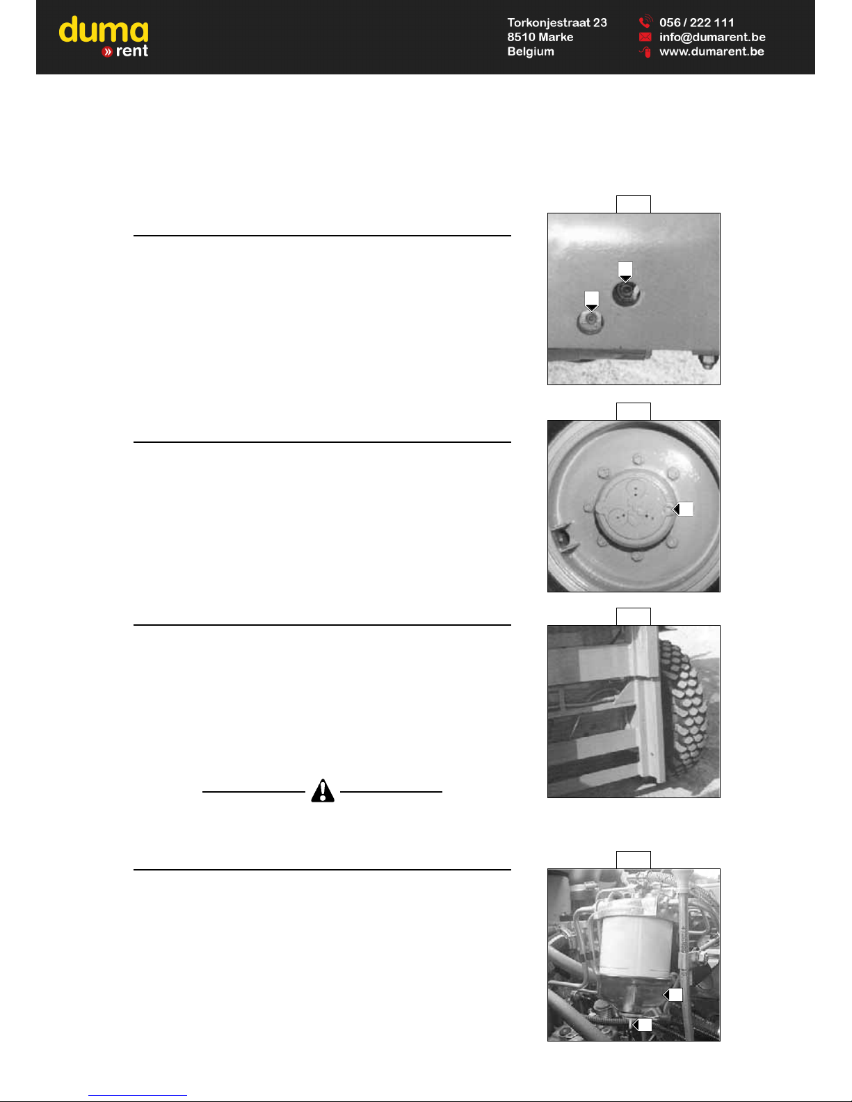
3 - 19
C4 - CHECK THE LEVEL OF THE FRONT AXLE
DIFFERENTIAL OIL
Place the lift truck on level ground with the engine stopped.
- Remove level plug 1 (Fig. C4). The oil should be flush with the edge of the
hole.
- If necessary, add oil (See chapter : LUBRICANTS AND FUEL in paragraph :
3 - MAINTENANCE) by the filler port 2 (Fig. C4).
-
Replace and tighten the level plug 1 (Fig. C4) (Tightening torque 34 to
49 N.m).
C5 - C HECK THE LEVEL OF THE FRONT WHEEL
REDUCER OIL
Place the lift truck on level ground with the engine stopped.
- Check the level on each front wheel reducer.
- Place level plug 1 (Fig. C5) in the horizontal position.
- Remove the level plug ; the oil should be flush with the edge of the hole.
- If necessary, add oil (See chapter : LUBRICANTS AND FUEL in paragraph :
3 - MAINTENANCE) by the same hole.
-
Replace and tighten the level plug 1 (Fig. C5) (Tightening torque 34 to 49 N.m).
C6 - CLEAN AND LUBRICATE THE MAST UPRIGHTS
OPERATION TO BE DONE BEFORE OPERATING A NEW LIFT TRUCK
AND ONCE AT 200 HOURS SERVICE.
- Clean and remove the grease on all the lenght of the mast uprights (See fig.
C6) Be very careful when the lift truck is used in very dusty atmosphere.
- Check carefully the differents rollers to discover any traces of wear and
change it if necessary.
- Lubricate very slightly with grease (See chapter : LUBRICANTS AND FUEL
in paragraph : 3 - MAINTENANCE) all the lenght of mast uprights.
In case of technical faults, consult your dealer.
C7 - DRAIN THE FUEL FILTER
- Open the engine bonnet.
- Visually check for the presence of water in tank 1 (Fig. C7) and drain if
necessary.
- Place a receptacle under the tank and loosen drain plug 2 (Fig. C7) by two
of three turns.
- Leave the diesel fuel to flow out until it is free from impurities and water.
- Tighten the drain plug while the diesel fuel is running out.
C5
C6
C7
1
C4
1
2
1
2
Page 90

3 - 20
D - EVERY 400 WORKING HOURS SERVICE
D1 - DRAIN AND CHANGE THE ENGINE OIL
D2 - CHANGE THE ENGINE OIL FILTER
Place the truck on level ground, let the engine run at idle for a few minutes,
then stop the engine.
DRAINING THE OIL
- Lift up the cabin (See chapter : INSTRUMENTS AND CONTROLS in
paragraph : 2 - DESCRIPTION).
- Remove the cover plate 1 (Fig. D1/1) (According to model).
- Place a container under drain plug 2 (Fig. D1/2) and unscrew the plug.
- Remove filler cap 3 (Fig. D1/3) in order to ensure that the oil is drained
properly.
Get rid of the drain oil in an ecological manner.
REPLACEMENT OF THE FILTER
- Remove engine oil filter 4 (Fig. D1/2) ; discard the filter and the filter seal.
- Clean the filter bracket with a clean, lint-free cloth.
- Lightly lubricate the new seal.
- Refit the oil filter on the filter bracket.
Tighten the oil filter by hand pressure only and lock the filter in place by a
quarter turn.
FILLING UP THE OIL
- Refit and tighten drain plug 2 (Fig. D1/2) (Tightening torque 30 to 40 N/m).
- Fill up with oil (See chapter : LUBRICANTS AND FUEL in paragraph : 3 MAINTENANCE) by filler port 5 (Fig. D1/3).
- Wait a few minutes to allow the oil to flow into the sump.
- Start the engine and let it run for a few minutes.
- Check for possible leaks at the drain plug and the oil filter.
- Stop the engine, wait a few minutes and check the level between the two
notches on dipstick 6 (Fig. D1/4).
- Top up the level if necessary.
- Remonter la trappe de fermeture 1 (Fig. D1/1) (Suivant montage).
- Put back the cover plate 1 (Fig. D1/1) (According to model).
D1/2
D1/3
D1/1
4
2
3
D1/4
6
1
5
Page 91
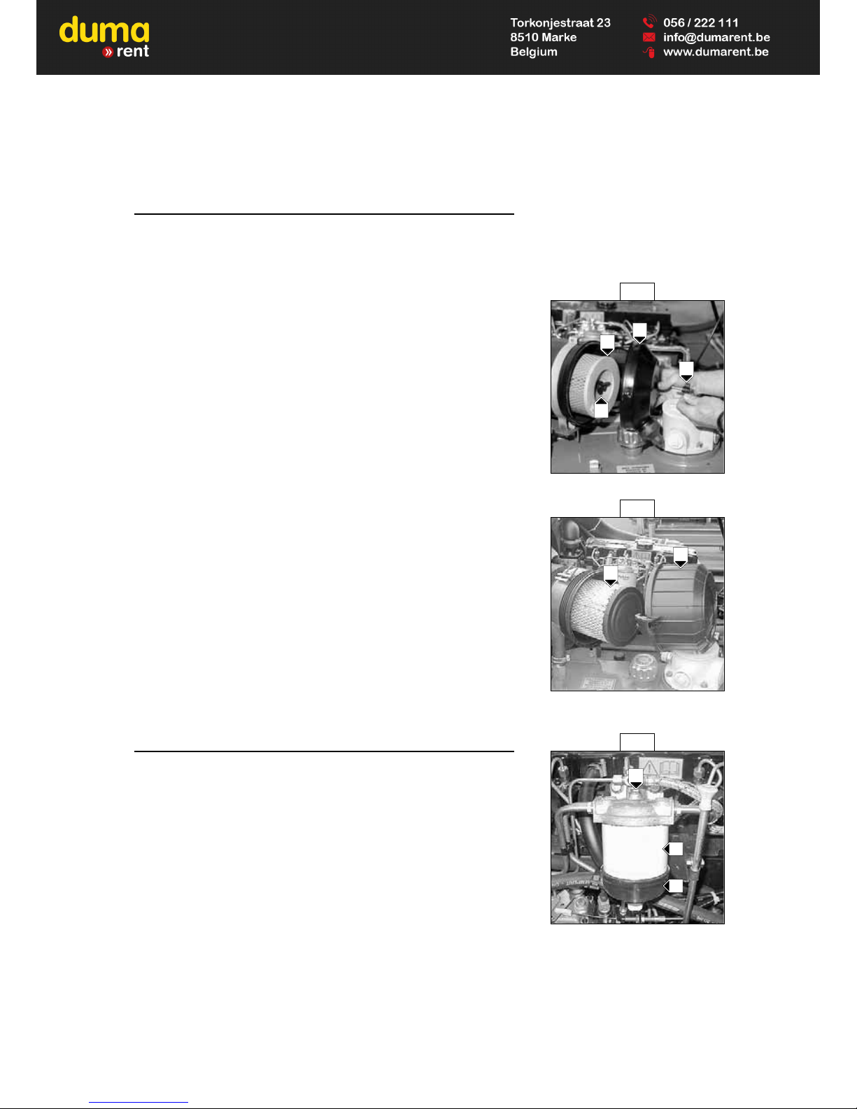
3 - 21
D3 - CHANGE THE DRY AIR FILTER CARTRIDGE
The air used to burn the fuel is purified by a dry air filter. It is therefore very
important that the lift truck should never be used with the cartridge removed
or damaged.
- Lift up the cabin (See chapter : INSTRUMENTS AND CONTROLS in
paragraph : 2 - DESCRIPTION).
UP TO MACHINE N° 142 126
- Unscrew nut 1 (Fig. D3/1) and remove cover 2 (Fig. D3/1).
- Unscrew nut 3 (Fig. D3/1) lift out and discard filter cartridge 4 (Fig. D3/1).
- Leave the safety cartridge in place.
- Clean the inside of the casing with a clean, damp lint free cloth.
- Refit the new cartridge and the cover.
In the event of the lift truck being used in a heavily dust laden atmosphere,
see chapter : FILTERS CARTRIDGES AND BELTS in paragraph : 3 MAINTENANCE.
FROM MACHINE N° 142 127
- Loosen the nuts and remove cover 1 (Fig. D3).
- Lift out and discard filter cartridge 2 (Fig. D3).
- Leave the safety cartridge in place.
- Clean the inside of the casing with a clean, damp lint free cloth. Also clean
the cartridge seal surfaces on the filter and cover.
- Then fit a new cartridge making sure it is in the correct position.
- Refit the cover, guiding the valve downwards.
In the event of the lift truck being used in a heavily dust laden atmosphere,
see chapter : FILTERS CARTRIDGES AND BELTS in paragraph : 3 MAINTENANCE.
D4 - CHANGE THE FUEL FILTER CARTRIDGE
- Lift up the cabin (See chapter : INSTRUMENTS AND CONTROLS in
paragraph : 2 - DESCRIPTION).
- Carefully clean the exterior of the filter and this bracket to prevent the dust
from entering the system.
- Unscrew locking screw 1 (Fig. D4).
- Remove tank 2 (Fig. D4) and discard cartridge 3 (Fig. D4) as well as the
seals of the cartridge.
- Clean the inside of the filter head and the tank, using a brush immersed in
clean diesel oil.
- Refit the assembly with a new cartridge and new seals.
If necessary, bleed the fuel circuit (See chapter : H1 - BLEED THE FUEL
SYSTEM in paragraph : 3 - MAINTENANCE).
D4
1
D3/1
1
2
3
4
D3/2
1
2
3
2
Page 92

3 - 22
D5 - CHANGE THE HYDRAULIC RETURN OIL FILTER
CARTRIDGE
Thoroughly clean the outside of the filter and its surroundings before any
intervention in order to prevent any risk of polluting the hydraulic circuit.
- Lift up the cabin (See chapter : INSTRUMENTS AND CONTROLS in
paragraph : 2 - DESCRIPTION).
- Unscrew the locking screws of the cover 1 (Fig. D5).
- Remove the hydraulic return oil filter cartridge 2 (Fig. D5), and fit new
replacement cartridge.
-
Make sure that the cartridge is correctly positioned and refit cover 1 (Fig. D5).
D6 - CHANGE THE OIL TANK BREATHER
- Lift up the cabin (See chapter : INSTRUMENTS AND CONTROLS in paragraph : 2 - DESCRIPTION).
- Unscrew the oil tank air breather 1 (fig. D6) and fit new replacement air
breather tighten by hand pressure only.
D7 - CHECK THE DENSITY OF THE BATTERY
ELECTROLYTE
The electrolyte density varies depending on the temperature concerned, but a
minimum of 1260 at 16° C must be maintained.
In the shaded area (Fig. D7), the battery is in a normal charge condition.
Readings above this zone indicate that the battery needs to be recharged.
The density should not vary more than 0.025 units between cells.
- Lift up the cabin (See chapter : INSTRUMENTS AND CONTROLS in
paragraph : 2 - DESCRIPTION).
- Check the electrolyte density in each battery cell using a hydrometer.
Do not carry out this check immediately after topping up with distilled water.
Recharge the battery for at least an hour before checking the battery
electrolyte density.
D7
1.240
1.250
1.260
1.270
1.280
1.290
1.300
-10
14
-18
0°C°F
0321050206830
86
40
104
D6 D6
1
Up to machine n° : 104 256 From machine n° : 104 257
1
D5
1
2
Page 93

3 - 23
Handling and servicing a battery can be dangerous, take the following
precautions :
- Wear protective goggles.
- Keep the battery horizontal.
- Never smoke or work near a naked flame.
- Work in a well-ventilated area.
- In the event of electrolyte being spilled onto the skin or splashing in the
eyes, rinse thoroughly with cold water for 15 minutes and call a doctor.
D8 - CLEAN THE FUEL LIFT PUMP
- Lift up the cabin (See chapter : INSTRUMENTS AND CONTROLS in
paragraph : 2 - DESCRIPTION).
- Unscrew retaining screw 1 (Fig. D8).
- Remove the strainer 2 (Fig. D8).
- Carefully clean the interior of fuel lift pump, strainer and cover using a brush
immersed in clean diesel oil.
- Refit the assembly and make sure that the connection between the cover
and the body of pump is perfectly right.
- Re-prime the fuel lift pump.
D9 - CHECK, CLEAN AND LUBRICATE THE MAST
LIFTING CHAINS
- Wipe the mast lifting chains 1 (Fig. D9) with a clean, lint-free cloth, then
examine them closely so as to detect any signs of wear.
- Vigorously brush the chains to get rid of any foreign matter, with a hard
nylon brush and clean diesel fuel.
- Rinse the chains by means of a paint brush impregnated with clean diesel
fuel and dry them with a compressed air jet.
- Moderately lubricate the chains with a paint brush impregnated with oil (See
chapter : LUBRICANTS AND FUEL in paragraph : 3 - MAINTENANCE).
- Remove the excess of oil with a clean cloth on the full length of the mast
lifting chains.
In case of technical faults, consult your dealer.
D10 - GREASE THE PARKING BRAKE LEVER
MECHANISM
- Release the protective boot 1 (Fig. D10).
- Clean and grease articulation axles 2 (Fig. D10) with grease (See chapter :
LUBRICANTS AND FUEL in paragraph : 3 - MAINTENANCE).
- Refit the protective boot 1 (Fig. D10).
D10
D9
1
1
2
2
2
D8
1
2
Page 94

3 - 24
E - EVERY 800 WORKING HOURS SERVICE
E1 - DRAIN AND CHANGE THE HYDRAULIC OIL
E2 - CLEAN THE SUCTION STRAINER OF THE
HYDRAULIC OIL TANK
E3 - CHANGE THE HYDROSTATIC TRANSMISSION OIL
FILTER CARTRIDGE
Place the lift truck on level ground with the I.C. engine stopped and the mast
lowered as far as possible.
DRAINING THE OIL
- Lift up the cabin (See chapter : INSTRUMENTS AND CONTROLS in
paragraph : 2 - DESCRIPTION).
Before any type of intervention, the drain plug surroundings should be carefully
cleaned.
- Place a container under the drain plug 1 (Fig. E1/1) and unscrew it.
- Unscrew the cover 2 (Fig. E1/2) to ensure that the oil is drained properly.
Dispose the drain oil in an ecological manner.
STRAINER CLEANING
FROM MACHINE N° : 115 593
- Disconnect the clogging indicator 3 (Fig. E1/3).
- Disconnect the hose 4 (Fig. E1/3) at the level of the hydrostatic transmission
oil filter 5 (Fig. E1/3).
- Unscrew the four screws 6 (Fig. E1/3) and remove the complete filter 5 (Fig.
E1/3).
- Unscrew the suction strainer at the bottom of the tank, clean it with the help
of a compressed air jet, check its condition and change it, if necessary.
- Reassemble the strainer, the filter and re-connect the clogging indicator.
HYDROSTATIC TRANSMISSION OIL FILTER CARTRIDGE CHANGE
- Unscrew the cap 7 (Fig. E1/4).
- Remove the hydrostatic transmission oil filter cartridge 8 (Fig. E1/4) and
replace it by a new one.
- Ensure that the cartridge is correctly positioned and refit the cover.
Do not operate the lift truck without a cartridge. This would immediately lead
to the deterioration of the hydraulic transmission circuit, the hydrostatic
pump and the hydrostatic motor.
FILLING UP OF OIL
- Clean and refit drain plug 1 (Fig. E1/1) (Tightening torque 29 to 39 N.m).
- Fill up with oil (See chapter : LUBRICANTS AND FUEL in paragraph : 3 MAINTENANCE) by filler port 9 (Fig. E1/2).
E1/2
E1/1
1
E1/3
E1/4
2
9
3
5
6
6
6
4
8
7
Page 95

3 - 25
Use a clean container and funnel and clean the underside of the oil drum
before filling.
- Examine the oil level on the cap-gauge 2 (Fig. E1/2), the oil level should be
equidistant between the lower and the upper marks.
- Check for any possible leak at the drain plug.
- Refit the cap-gauge 2 (Fig. E1/2).
It may be necessary to bleed the system at the inlet of the pumps, if any air
bubbles have formed during the draining; if so, consult your dealer.
POLLUTION ABATEMENT OF THE HYDRAULIC CIRCUIT
FROM MACHINE N° : 115 593
- Let the engine run (Accelerator pedal at halfway travel) for 5 minutes without
using anything on the lift truck, then for 5 more minutes while using
completely the hydraulic movements (Except the steering system and the
service brakes).
- Accelerate the engine at full speed for 1 minute, then activate the steering
system and the service brakes.
This operation makes a pollution abatement of the circuit possible through the
hydraulic return oil filter.
E4 - DRAIN AND CHANGE THE TRANSFER BOX OIL
Place the lift truck on level ground with the engine stopped, the transfer box
oil still warm.
- Lift up the cabin (See chapter : INSTRUMENTS AND CONTROLS in
paragraph : 2 - DESCRIPTION).
- Place a container under drain plug 1 (Fig. E4) and unscrew the plug.
- Remove level and filler cap 2 (Fig. E4) in order to ensure that the oil is
drained properly.
Get rid of the drain oil in an ecological manner.
- Refit and tighten drain plug 1 (Fig. E4) (Tightening torque 29 to 39 N.m).
- Fill up with oil (See chapter : LUBRICANTS AND FUEL in paragraph : 3 MAINTENANCE) by filler port 2 (Fig. E4).
- The level is correct when the oil is flush with the edge of the hole.
- Check for any possible leaks at the drain plug.
- Refit and tighten level and filler cap 2 (Fig. E4) (Tightening torque 29 to 39
N.m).
E4
1
2
Page 96

3 - 26
E5 - DRAIN AND CHANGE THE FRONT AXLE
DIFFERENTIAL OIL
Place the truck on level ground with the engine stopped and the differential oil
still warm.
- Place a container under the drain plugs 1 (Fig. E5/1) and unscrew them.
- Remove the filler plug 2 (Fig. E5/1) and the level plug 3 (Fig. E5/1) so as to
ensure a good draining.
Dispose the drain oil in an ecological manner.
- Refit and tighten drain plugs 1 (Fig. E5/1) (Tightening torque 34 to 49 N.m).
- Fill up with oil (See chapter : LUBRICANTS AND FUEL in paragraph : 3 MAINTENANCE) by filler port 2 (Fig. E5/2).
- The level is correct when the oil level is flush with the edge of port 3 (Fig.
E5/2).
- Check for any possible leaks at the drain plugs.
- Refit and tighten the filler plug 2 (Fig. E5/2) and the level plug 3 (Fig. E5/2).
(Tightening torque 34 to 49 N.m).
E6 - DRAIN AND CHANGE THE FRONT WHEEL
REDUCER OIL
Place the lift truck on level ground with the engine stopped and the reducers
oil still warm.
- Drain and change each front wheel reducer.
- Place drain plug 1 (Fig. E6) in position A.
- Place a container under the drain plug and unscrew the plug.
- Let the oil drain fully.
Dispose the drain oil in an ecological manner.
- Place the drain port in position B, (Fig. E6) in a level port.
- Fill up with oil (See chapter : LUBRICANTS AND FUEL in paragraph : 3 MAINTENANCE) by level port 1 (Fig. E6).
- The level is correct when the oil level is flush with the edge of the hole.
- Refit and tighten the drain plug 1 (Fig. E6) (Tightening torque 34 to 49 N.m).
E6
E5/1
E5/2
A
B
1
1
1
2
3
1
Page 97

3 - 27
E7 - DRAIN AND CHANGE THE COOLING LIQUID
These operations are to be carried out if necessary or once a year at the
coming of winter.
Place the truck on level ground with the engine stopped and cold.
LIQUID DRAINING
- Lift up the cabin (See chapter : INSTRUMENTS AND CONTROLS in
paragraph : 2 - DESCRIPTION).
- Open the tap 1 (fig. A7/1) of the radiator.
- Untighten the drain plug 2 (Fig. E7/2) of the engine block.
- Unscrew the filler plug 3 (Fig. E7/3) of the expansion pan and empty the
latter.
- Remove the filler plug 5 (Fig. E7/5) of the radiator.
- Allow the cooling circuit to drain completely while ensuring that the ports do
not get clogged.
- Check the condition of the hoses as well as the fastening devices and
change the hoses if necessary.
- Rinse the circuit with clean water and use a cleaning product if necessary.
LIQUID FILLING
- Close the tap 1 (fig. A7/1).
- Retighten the drain plug 2 (Fig. E7/2) (Tightening torque 7 to 12 N/m).
-
Slowly and completely fill the cooling circuit (See chapter : LUBRICANTS
AND FUEL in paragraph : 3 - MAINTENANCE)via the filler port 5 (Fig. E7/4).
- Fill the expansion pan to the maximum level.
- Allow the engine to run at idle for a few minutes.
- Check for possible leaks.
- Check the level and top up if necessary.
- Refit the filler plug 4 (Fig. E7/4).
- Screw the filler plug 3 (Fig. E7/3)
The engine does not contain any corrosion resistor and must be filled during
the whole year with a mixture containing 25 % of ethylene glycol-based anti-
freeze.
E7/1
E7/2
E7/3
E7/4
4
5
1
2
3
Page 98

3 - 28
E8 - DRAIN AND CLEAN THE FUEL TANK
While carrying out these operations, do not smoke or work near a flame.
Place the lift truck on level ground with the engine stopped.
- Lift up the cabin (See chapter : INSTRUMENTS AND CONTROLS in
paragraph : 2 - DESCRIPTION).
- Inspect the parts susceptible to leaks in the fuel circuit and in the tank.
- In the event of a leak, contact your dealer.
Never try to carry out a weld or any other operation by yourself, this could
provoke an explosion or a fire.
- Place a container under drain plug 1 (Fig. E8/1) and unscrew the plug.
- Remove cap 2 (Fig. E8/2).
- Let the fuel flow and clean with 10 litres of clean fuel by filler port 3 (Fig.
E8/2).
- Refit and tighten drain plug 1 (Fig. E8/1) (Tightening torque 29 to 39 N.m).
- Fill the fuel tank with clean fuel (See chapter : LUBRICANTS AND FUEL in
paragraph : 3 - MAINTENANCE) filtered through a strainer or a clean, lintfree cloth and refit the filler plug 2 (Fig. E8/2).
- Re-prime the system by activating fuel feed pump 4 (Fig. E8/3).
- If necessary, bleed the system (See chapter : H1 - BLEED THE FUEL
SYSTEM in paragraph : 3 - MAINTENANCE).
E9 - CHANGE THE SAFETY DRY AIR FILTER
CARTRIDGE
- Lift up the cabin (See chapter : INSTRUMENTS AND CONTROLS in
paragraph : 2 - DESCRIPTION).
- Disassemble the dry air filter cartridge (See chapter : D3 - CHANGE THE
DRY AIR FILTER CARTRIDGE in paragraph : 3 - MAINTENANCE).
UP TO MACHINE N° 142 126
- Remove air filter safety cartridge 1 (Fig. E9/1) and replace the safety
cartridge concerned with a new cartridge.
E8/1
E8/2
E8/3
E9/1
1
1
2
3
4
Page 99

3 - 29
FROM MACHINE N° 142 127
- Remove air filter safety cartridge 1 (Fig. E9/2) and replace the safety
cartridge concerned with a new cartridge.
- Reassemble the entire unit (See chapter : D3 - CHANGE THE DRY AIR
FILTER CARTRIDGE in paragraph : 3 - MAINTENANCE).
E10 - CLEAN THE HEATING SUCTION FILTER
- Lift up the cabin (See chapter : INSTRUMENTS AND CONTROLS in
paragraph : 2 - DESCRIPTION).
- Loosen the knurled nuts 1 (Fig. E10/1) and remove the washers.
- Remove the heating suction filter 2 (Fig. E10/2).
- Clean the filter by means of a compressed air jet.
- Check its condition and change it if necessary.
- Reassemble the whole.
E10/2
E10/1
1
1
2
E9/2
1
Page 100

3 - 30
H1 - BLEED THE FUEL SYSTEM
These operations are to be carried out only in the following cases :
- A component of the fuel system replaced or drained.
- A drained tank.
- Running out of fuel.
Ensure that the level of fuel in the tank is sufficient, turn the ignition key to
notch I to establish electrical contact and bleed in the following order :
- Lift up the cabin (See chapter : INSTRUMENTS AND CONTROLS in
paragraph : 2 - DESCRIPTION).
BLEEDING THE FUEL FILTER
- Loosen bleed screw 1 (Fig. H1/1).
- Activate feed pump 2 (Fig. H1/2) until the diesel fuel flows out free from air
at the bleed screw.
NOTE : If the lever on the feed pump is in the maximum raised position, turn
the crankshaft by one turn.
- Tighten the bleed screw while the diesel fuel is flowing out.
BLEEDING THE HEATER PLUG
- Loosen connection 3 (Fig. H1/3) on the heater plug.
- Activate feed pump 2 (Fig. H1/2) until the diesel fuel is flowing out free from
air at the connection.
- Tighten the connection while the diesel fuel is flowing out.
Immobilise the heater plug with a spanner before loosening connection 3
(Fig. H1/3).
BLEEDING THE INJECTION PUMP
- Loosen connection 4 (Fig. H1/4) of the low pressure fuel return circuit on the
regulator housing.
- Activate feed pump 2 (Fig. H1/2) until the diesel fuel is flowing out free from
air at the connection.
- Tighten the connection while the diesel fuel is flowing out.
H - OCCASIONAL MAINTENANCE
H1/1
H1/2
H1/3
H1/4
1
2
3
4
 Loading...