

Man D 2840 LE 403, D 2842 LE 410, D 2842 LE 414, D 2842 LE 415, D 2842 LE 416 Operating Instructions Manual
...Page 1

Page 2

Page 3

3
Operating Instructions –
MAN Marine Diesel Engines
Page 4

4
Page 5

Preface
5
Dear Customer,
these Operating Instructions are intended to familiarize you with your new MAN Diesel
engine and how it operates.
This manual is supplemented by the publication “Fuels, Lubricants and Coolants for MAN
Diesel Engines” and the “Service record book”.
Note:
All three publications belong to the engine and must always be kept ready to
hand near the engine in the engine room.
Comply in full with instructions relating to operation, prevention of accidents and
environmental protection.
MAN Diesel engines are developed and manufactured in line with the latest state of the
art. However, trouble-free operation and high performance can only be achieved if the
specified maintenance intervals are observed and only approved fuels, lubricants and
coolants are used.
It is imperative and in your own interest to entrust your MAN Local Service Centre with
the removal of any disturbances and with the performance of checking, setting, and
repair work.
Yours faithfully,
MAN Nutzfahrzeuge Aktiengesellschaft
Werk Nürnberg
Subject to change to keep abreast with technological progress.
2003 MAN Nutzfahrzeuge Aktiengesellschaft
No parts of this publication may be reproduced or translated without prior written permission of MAN. MAN explicitly reservs all rights according to copyright law.
MTDA Technical status: 04.2003 51.99493–8496
Page 6

Instructions
6
Important instructions which concern technical safety and protection of persons are emphasised as shown below.
Danger:
This refers to working and operating procedures which must be complied with in
order to rule out the risk to persons.
Caution:
This refers to working and operating procedures which must be complied with in
order to prevent damage to or destruction of material.
Note:
Explanations useful for understanding the working or operating procedure to be
performed.
Fitting flat seals / gaskets
Flat seals / gaskets are often inserted with sealing agents or adhesives to make fitting
them easier or to achieve better sealing. Flat seals may slip in operation due to the “sewing-machine” effect, in particular if they are used between parts with different rates of linear expansion under heat (e.g. aluminium and cast iron), and leaks may then occur.
Example:
the cap of the front crankshaft seal. If a sealing agent or an adhesive is used here the flat
seal will move inwards in the course of time as a result of the different expansion rates of
the materials. Oil will be lost, for which the shaft seal may be thought to be responsible.
Flat seals / gaskets can be fitted properly only if the following points are observed:
D Use only genuine MAN seals / gaskets
D The sealing faces must be undamaged and clean
D Do not use any sealing agent or adhesive – as an aid to fitting the seals a little grease
can be used if necessary so that the seal will stick to the part to be fitted
D Tighten bolts evenly to the specified torque
Page 7

Contents
7
Page
Declaration 8 . . . . . . . . . . . . . . . . . . . . . . . . . . . . . . . . . . . . . . . . . . . . . . . . . . . . . . . . . . . . . . .
Nameplates 9 . . . . . . . . . . . . . . . . . . . . . . . . . . . . . . . . . . . . . . . . . . . . . . . . . . . . . . . . . . . . . . .
Safety regulations 10 . . . . . . . . . . . . . . . . . . . . . . . . . . . . . . . . . . . . . . . . . . . . . . . . . . . . . . . . .
Commissioning and operation 14 . . . . . . . . . . . . . . . . . . . . . . . . . . . . . . . . . . . . . . . . . . . . .
Engine views 14 . . . . . . . . . . . . . . . . . . . . . . . . . . . . . . . . . . . . . . . . . . . . . . . . . . . . . . . . . . . .
First commissioning 16 . . . . . . . . . . . . . . . . . . . . . . . . . . . . . . . . . . . . . . . . . . . . . . . . . . . . . .
Commissioning 18 . . . . . . . . . . . . . . . . . . . . . . . . . . . . . . . . . . . . . . . . . . . . . . . . . . . . . . . . . .
Starting 19 . . . . . . . . . . . . . . . . . . . . . . . . . . . . . . . . . . . . . . . . . . . . . . . . . . . . . . . . . . . . . . . . .
Operation monitoring 20 . . . . . . . . . . . . . . . . . . . . . . . . . . . . . . . . . . . . . . . . . . . . . . . . . . . . .
Shutting down 49 . . . . . . . . . . . . . . . . . . . . . . . . . . . . . . . . . . . . . . . . . . . . . . . . . . . . . . . . . . .
Maintenance and care 50 . . . . . . . . . . . . . . . . . . . . . . . . . . . . . . . . . . . . . . . . . . . . . . . . . . . . .
Lubrication system 50 . . . . . . . . . . . . . . . . . . . . . . . . . . . . . . . . . . . . . . . . . . . . . . . . . . . . . . .
Fuel system 53 . . . . . . . . . . . . . . . . . . . . . . . . . . . . . . . . . . . . . . . . . . . . . . . . . . . . . . . . . . . . .
Cooling system 56 . . . . . . . . . . . . . . . . . . . . . . . . . . . . . . . . . . . . . . . . . . . . . . . . . . . . . . . . . .
V-belts 59 . . . . . . . . . . . . . . . . . . . . . . . . . . . . . . . . . . . . . . . . . . . . . . . . . . . . . . . . . . . . . . . . . .
Alternator 61 . . . . . . . . . . . . . . . . . . . . . . . . . . . . . . . . . . . . . . . . . . . . . . . . . . . . . . . . . . . . . . .
Temporary decommissioning of engines 61 . . . . . . . . . . . . . . . . . . . . . . . . . . . . . . . . . . . .
Technical data 62 . . . . . . . . . . . . . . . . . . . . . . . . . . . . . . . . . . . . . . . . . . . . . . . . . . . . . . . . . . . .
Troubleshooting table 66 . . . . . . . . . . . . . . . . . . . . . . . . . . . . . . . . . . . . . . . . . . . . . . . . . . . . .
Index 68 . . . . . . . . . . . . . . . . . . . . . . . . . . . . . . . . . . . . . . . . . . . . . . . . . . . . . . . . . . . . . . . . . . . . .
Page 8

For data see original declaration
If required this declaration is
enclosed with the delivery note.
Declaration
8
Declaration
In accordance with Article 4, paragraph 2, in conjunction with Appendix II, section B, of
Directive 89/392/EEC, version 93/44/EEC
MAN Nutzfahrzeuge Aktiengesellschaft,
hereby declares that the engine described below is destined for installation in a machine
as defined in the EC directive on machines.
Engine model:
Design:
Engine number:
Rating / speed:
Note:
The manufacturer of the complete ready-to-use machine in which this engine is
to be installed must take the further action necessary in the context of indirect
safety-related engineering and provision of instructions to ensure that the readyto-use machine complies with the requirements of the EC directive on machines.
The engine must not be put into operation until the complete machine satisfies
the conditions laid down in the EC directive on machines 89/392/EEC, most recently amended by 93/44/EEC, or the latest amendment of said directive.
MAN Nutzfahrzeuge Aktiengesellschaft
Vogelweiherstraße 33
D–90441 Nürnberg
Page 9

Nameplates
9
In all your correspondence please always
quote engine model, serial number and job
number (Order number).
For this reason it is advisable to read off the
data from the engine type plates before
putting the engine into operation and to
enter them in the appropriate spaces.
The engine type plates are on the crankcase (see illustration).
Model
......................................................................
delivered on
......................................................................
installed on
......................................................................
Engine serial number
......................................................................
Order number
......................................................................
MAN Nutzfahrzeuge Aktiengesellschaft
Typ
Motor-Nr. / Engine No.
NI/II
Temp. C
Werk Nürnberg Germany
:
MAN Nutzfahrzeuge AktiengesellscMAN Nutzfahrzeuge Aktiengesellschaft
:
:
Altitude mRating BHP
Job No Rating kW
Speed rpm
Serial NoModelYear
–0219
Aufstellhohe m uNNLeistg. PS
Drehz. 1/min
Leistung kWWerk–Nr.
Motor–Nr.TypBauj.
°
Page 10

Safety regulations
10
General notes
Handling diesel engines and the necessary resources is no problem when the personnel commissioned with operation and maintenance are trained accordingly
and use their common sense.
This summary is a compilation of the most important regulations. These are broken down
into main sections which contain the information necessary for preventing injury to persons, damage to property and pollution. In addition to these regulations those dictated by
the type of engine and its site are to be observed also.
Important:
If, despite all precautions, an accident occurs, in particular through contact with caustic
acids, fuel penetrating the skin, scalding from hot oil, anti-freeze being splashed in the
eyes etc., consult a doctor immediately.
1. Regulations designed to prevent accidents with injury to persons
During commissioning, starting and operation
D Before putting the engine into operation for the first time, read the oper-
ating instructions carefully and familiarize yourself with the “critical”
points. If you are unsure, ask your MAN representative.
D For reasons of safety we recommend you attach a notice to the door of
the engine room prohibiting the access of unauthorized persons and that
you draw the attention of the operating personal to the fact that they are
responsible for the safety of persons who enter the engine room.
D The engine must be started and operated only by authorized personnel.
Ensure that the engine cannot be started by unauthorized persons.
D When the engine is running, do not get too close to the rotating parts.
Wear close-fitting clothing.
D Do not touch the engine with bare hands when it is warm from operation
– risk of burns.
D Exhaust gases are toxic. Comply with the instructions for the installation
of MAN Diesel engines which are to be operated in enclosed spaces.
Ensure that there is adequate ventilation and air extraction.
D Keep vicinity of engine, ladders and stairways free of oil and grease.
Accidents caused by slipping can have serious consequences.
Page 11

Safety regulations
11
During maintenance and care
D Always carry out maintenance work when the engine is switched off.
If the engine has to be maintained while it is running, e.g. changing the
elements of change-over filters, remember that there is a risk of scalding. Do not get too close to rotating parts.
D Change the oil when the engines is warm from operation.
Caution:
There is a risk of burns and scalding. Do not touch oil drain plugs or oil
filters with bare hands.
ËË
D Take into account the amount of oil in the sump. Use a vessel of suffi-
cient size to ensure that the oil will not overflow.
D Open the coolant circuit only when the engine has cooled down.
If opening while the engine is still warm is unavoidable, comply with the
instructions in the chapter entitled “Maintenance and Care”.
D Neither tighten up nor open pipes and hoses (lube oil circuit, coolant cir-
cuit and any additional hydraulic oil circuit) during the operation.
The fluids which flow out can cause injury.
D Fuel is inflammable. Do not smoke or use naked lights in its vicinity. The
tank must be filled only when the engine is switched off.
D When using compressed air, e.g. for cleaning the radiator, wear goggles.
D Keep service products (anti-freeze) only in containers which can not be
confused with drinks containers.
D Comply with the manufacturer’s instructions when handling batteries.
Caution:
Accumulator acid is toxic and caustic. Battery gases are explosive.
Page 12

Safety regulations
12
2. Regulations designed to prevent damage to engine and premature wear
Do not demand more from the engine than it is able to supply in its intended application.
Detailed information on this can be found in the sales literature. The injection pump must
not be adjusted without prior written permission of MAN Nürnberg.
If faults occur, find the cause immediately and have it eliminated in order to prevent more
serious damage.
Use only genuine MAN spare parts. MAN will accept no responsibility for damage resulting from the installation of other parts which are supposedly “just as good”.
In addition to the above, note the following points:
D Never let the engine run when dry, i.e. without lube oil or coolant.
D When starting do not use any additional starting aids (e.g. injection with starting pilot).
D Use only MAN-approved service products (fuel, engine oil, anti-freeze and anti-cor-
rosion agent). Pay attention to cleanliness. The Diesel fuel must be free of water. See
“Maintenance and care”.
D Have the engine maintained at the specified intervals.
D Do not switch off the engine immediately when it is warm, but let it run without load for
about 5 minutes so that temperature equalization can take place.
D Never put cold coolant into an overheated engine. See “Maintenance and care”.
D Do not add so much engine oil that the oil level rises above the max. marking on
the dipstick. Do not exceed the maximum permissible tilt of the engine.
Serious damage to the engine may result if these instructions are not adhered to.
D Always ensure that the testing and monitoring equipment (for battery charge, oil pres-
sure, coolant temperature) function satisfactorily.
D Comply with instructions for operation of the alternator. See “Maintenance and care”.
D Do not let the raw water pump run dry. If there is a risk of frost, drain the pump when
the engine is switched off.
3. Regulations designed to prevent pollution
Engine oil and filter elements / cartridges, fuel / fuel filter
D Take old oil only to an old oil collection point.
Page 13

Safety regulations
13
D Take strict precautions to ensure that no oil or Diesel fuel gets into the drains or the
ground.
Caution:
The drinking water supply could be contaminated.
D Filter elements are classed as dangerous waste and must be treated as such.
Coolant
D Treat undiluted anti-corrosion agent and / or anti-freeze as dangerous waste.
D When disposing of spent coolant comply with the regulations of the relevant local auth-
orities.
4. Notes on safety in handling used engine oil ∗
Prolonged or repeated contact between the skin and any kind of engine oil decreases the
skin. Drying, irritation or inflammation of the skin may therefore occur. Used engine oil
also contains dangerous substances which have caused skin cancer in animal experiments. If the basic rules of hygiene and health and safety at work are observed, health
risks are not to the expected as a result of handling used engine oil.
Health precautions:
D Avoid prolonged or repeated skin contact with used engine oil.
D Protect your skin by means of suitable agents (creams etc.) or wear protective gloves.
D Clean skin which has been in contact with engine oil.
– Wash thoroughly with soap and water. A nailbrush is an effective aid.
– Certain products make it easier to clean your hands.
– Do not use petrol, Diesel fuel, gas oil, thinners or solvents as washing agents.
D After washing apply a fatty skin cream to the skin.
D Change oil-soaked clothing and shoes.
D Do not put oily rags into your pockets.
Ensure that used engine oil is disposed of properly
– Engine oil can endanger the water supply –
For this reason do not let engine oil get into the ground, waterways, the drains or the
sewers. Violations are punishable.
Collect and dispose of used engine oil carefully. For information on collection points
please contact the seller, the supplier or the local authorities.
∗ Adapted from “Notes on handling used engine oil”.
Page 14

Commissioning and operation
14
Engine views D 2840 LE 403
1 2 3 4 5 6 7 8
910111213
8 7 6
918 17 16 15 14
Page 15

Commissioning and operation
15
1 Heat exchanger and coolant surge tank
2 Relief valve on coolant surge tank
3 Intercooler
4 Coolant filler neck
5 Oil filler neck
6 Oil separator valve for crankcase breather
7 Air intake
8 Turbocharger
9 Exhaust pipe
10 Oil dipstick
11 Starter motor
12 Oil sump
13 Engine cranking device
14 Alternator
15 Water pump (engine coolant circuit)
16 Oil drain plug
17 Speed sender
18 Oil filter
Page 16

Commissioning and operation
16
First commissioning
When putting a new or overhauled engine into operation for the first time pay attention to
the “Installation instructions for MAN marine diesel engines” without fail.
It is recommended that new or overhauled engines should not be operated at a load
higher than about 75% maximum load during the first few hours of operation. Initial run-in
should be at varying speeds. After this initial run-in, the engine should be brought up to
full output gradually.
Note:
Use only approved fuels, lubricants etc. (see brochure “Fuels, lubricants etc.”).
Otherwise the manufacturer’s warranty will become null and void.
Filling with fuel
Caution:
Fill the tank only when the engine is switched off. Pay attention to cleanliness.
Do not spill fuel.
Use only approved fuels (see “Fuels, Lubricants etc.”).
Filling-in of coolant
Fill the cooling system of the engine with a mixture of drinkable tap water and anti-freeze
agent on ethylene glycole basis or anti-corrosion agent.
See Publication “Fuels, Lubricants and Coolants for MAN Diesel Engines”.
D Pour in coolant slowly via expansion tank, see page 57
D For coolant filling quantity, see “Technical data”
Page 17

Commissioning and operation
17
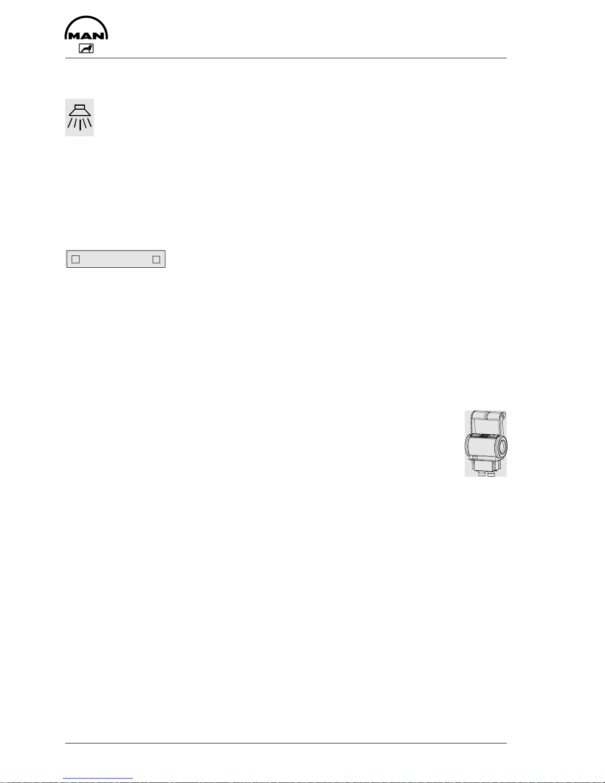
Raw water pump
Do not let raw water pump run dry.
Make sure that all valves / cocks in the
raw water circuit are open.
If there is a risk of frost, drain the raw water pump.
Filling with engine oil
Caution:
Do not add so much engine oil
that the oil level rises above the
max. marking on the dipstick.
Overfilling will result in damage to
the engine.
The engines are as a rule supplied without oil.
Pour oil into engine via filler neck (arrow),
see page 51.
For the quantity required see “Technical
Data”.
Page 18

Commissioning and operation
18
Commissioning
Before daily starting the engine, check fuel level, coolant level and engine oil level and
replenish, if necessary.
Note:
Use only approved fuels, lubricants etc. (see brochure “Fuels, lubricants etc.”).
Otherwise the manufacturer’s warranty will become null and void.
Checking oil level
Check engine oil level only approx.
20 minutes after the unit has been
switched off.
D Pull out dipstick (arrow)
D wipe it with a clean, lintfree cloth
D and push it in again up to the stop
D Pull out dipstick again
The oil level should be between the two
notches in the dipstick and must never fall
below the lower notch. Top up oil as necessary.
Caution:
Do not add so much engine oil
that the oil level rises above the
max. marking on the dipstick.
Overfilling will result in damage to
the engine.
Ensure outmost cleanliness when handling fuels, lubricants and coolants.
Oil
?
MIN
MAX
Page 19

Commissioning and operation
19
Starting
Danger:
Before starting make sure that no-one is in the engine’s danger area.
Caution:
When starting do not use any additional starting aids (e.g. injection with starting
pilot).
Ensure that the gearbox is in neutral.
Insert starter key and turn it to position “I”. The check lamp comes on to show that the
engine is ready for operation.
Turn starter key further to position “II” (pre-glow). The display lamp (usually in the driver’s
station) comes on.
After the pre-glow period the display lamp begins to flash. This signalizes that the engine
is ready for starting.
Note:
If the engine is not equipped with a pre-glowing function, immediately turn the
starter key through to position “III”.
Turn key further up to the stop (position “III”). The display lamp goes out. The starter motor is actuated.
Lube oil pressure must build up at the oil pressure gauge. If it does not, switch off the engine immediately.
Do not operate starter for longer than 10 seconds at a time.
After ignition of the engine, release the starter button and adjust control lever for desired
speed.
If engine fails to start, release the key, wait about 30 seconds, then operate starter again.
For repeated starting turn the key back to OFF.
If the engine is kept idling for long periods it may cool down and thus start to emit white
or blue smoke.
We therefore recommend that you do not let the engine idle for more than 5 minutes.
It is well known that with any internal combustion engine wear is higher during idling.
Idling for longer periods is also an environmental nuisance.
Page 20

Commissioning and operation
20
Operation monitoring
The D 2840 LE 403 / D 2842 LE 404 is equipped as series standard with a monitoring
and diagnostic system MMDS.
On the control console and alternatively on other control stands, the following display devices are available for monitoring operation:
1. Analog round instruments, see below
2. Display device MMDS-L, see page 21
3. Display device MMDS-LC, see page 23
4. Engine room panel MMDS-EP, see page 31
For operation and speed adjustment, MAN provides the following equipment:
5. Drive lever control system Mini Marex made by Mannesmann-Rexroth, see page 32
6. Optional: Emergency unit Em, see page 42
1. Round instruments
MAN can supply the following VDO round instruments for operation monitoring:
Revolution counter with integrated digital hours of operation counter
Oil pressure engine 0–6 bar
Oil pressure gearbox 0–25 bar
Oil temperature engine 50–150°C
Coolant temperature engine 40–120°C
Exhaust temperature engine 100–900°C
Voltmeter 18–32 V
Page 21

Commissioning and operation
21
2. Display device MMDS-L
The engine monitoring alarms the officer
guiding the ship when important engine
operating values are outside the permitted
tolerance range.
D Acoustically by means of an integrated
buzzer or horn connected at the shipyard
D Visually in that the relevant warning
lamp flashes
The engine operating parameters shown
on the display device are monitored.
If gearbox parameters are to be monitored, this depends whether the corresponding sensors have been fitted in the
gearbox.
51.27720–7008
System
Fault
RESET
Alarm
TYP MMDS–L
MAN MARINE DIESEL
Engine slow down
Engine coolant temp.
Electronics failure
Boost pressure
Exhaust gas temperature
Charge air temperature
Gearbox oil pressure
Engine oil pressure
Cool. press. expans. tank
Overspeed
Generator/speed sensor
Coolant level
Engine in operation
TEST
Sensor failure
Pressure air filter
Cool. press. water pump
Engine oil temperature
Gearbox oil temperature
The device distinguishes between the following types of alarm, error messages:
D Preliminary alarm: the corresponding light-emitting diode flashes
D Main alarm: the corresponding light-emitting diode flashes
light-emitting diode “Alarm” flashes
In the case of an engine slow down alarm,
“Engine slow down” also flashes
In the case of a stop alarm, “Engine stop” also flashes
D Sensor fault: the corresponding light-emitting diode flashes
light-emitting diode “Sensor fault” flashes
The alarm “Sensor fault” means that the corresponding sensor is classified by the monitoring system as defective, as it is returning an unrealistic value.
The engine speed is not reduced.
In the event of a fault in the electronic system, the warning lamp lights up continuously.
There is then a defect in the electronic fuel injection (EDC).
So as not to endanger the engine, the engine power is automatically reduced in the case
of selected main alarms.
Note for engines with electronically controlled diesel injection (EDC):
After the ignition has been switched on, the lamp “Electronic fault” lights up briefly
(lamp test). If there is a fault in the electronically controlled diesel injection (EDC),
the lamp “Electronic fault” lights up permanently.
Page 22

Commissioning and operation
22
Operation of the display device MMDS-L
The display device has the following operating keys:
Switches off the alarm horn and the integrated buzzer
Switches off the flashing signal of the relevant warning lamp, i.e. the flashing light
switches to continuous light. Before the flashing signal is cleared, the alarm horn
must be switched off.
Clears the alarm message (red warning lamp goes out)
Requirement for clearing an alarm message is:
– Pressing the keys “Horn off” and “Test” in that order
– Removing the cause of the alarm
– In the event of a reduction alarm the engine speed must be brought down
below 800 rpm in order to be able to reach higher speeds again
– In the case of a stop alarm, the alarm can only be deleted if the engine is at a
standstill
Function test of the warning lamps
If there is no alarm, the warning lamps can be tested.
When the “Test” key is pressed, all the warning lamps must light up
Dimming
All alarm LEDs are dimmed automatically depending on the ambient brightness. A photoelectric element integrated in the front plate ensures this.
Horn test
If the ’Clear horn’ key is pressed for approx. 5 seconds, the fitted buzzer as well as possibly horns fitted at the shipyard go off.
System Failure
Two failure states are distinguished and indicated by the failure LED flashing or lighting
up continuously:
D A flashing System Failure LED signals a communication fault, i.e. the data bus is inter-
rupted or there is interference. In this case, the seating of plug-in connections for the
MMDS-L and the serial distributor MMDS-SD are to be checked.
D Continuous lighting up of the System Failure LED indicates an internal fault. If this
state remains after switching off and on again, the device is defective.
Page 23

Commissioning and operation
23
3. Display device MMDS-LC
The device serves to visualise analog engine data, as well as visual and acoustic
notification of engine alarms. All engine
data is entered at the factory in the languages German, English, French, Italian and Spanish.
“Scrolling” with the PAGE key enables the
user to call up all the important engine
data. Another key is used to show current
alarms or warnings.
Motordrehzahl 1835 upm
Oeltemp. Motor 120 C
Ladelufttemperatur 64 C
Kuehlwassertemp.Motor 83 C
Oeldruck Motor 4.3 bar
M
1
A
3
ALARMS
Men
PAGE RESET
Prg
Engine run
System fail.
Alarm
MAN MARINE DIESEL
TYP MMDS–LC
TEST
51.27720–7015
Page 24

Commissioning and operation
24
Representation of monitor pages
The analog engine data provided by the MMDS is distributed on 4 monitor pages. On
each page, the current engine speed is displayed in the top line. The 1st page continues
with the most important engine data such as oil pressure, coolant pressure, charge-air
pressure and oil pressure in the gearbox. Other engine and gearbox data, as well as exhaust temperatures and supplementary information is shown on the subsequent pages:
Page 1 Actual value (example)
P1 Engine speed 2100 rpm
Oil pressure, engine 4,3 bar
Coolant temperature, engine 82 °C
Charge-air temperature 41 °C
Oil pressure, gearbox 19 bar
Page 2 Actual value (example)
P2 Engine speed 2100 rpm
Coolant pressure compensator
reservoir
830 mbar
Coolant pressure water pump 3,9 bar
Oil temperature, engine 103 °C
Battery voltage 27,1 V
Page 3 Actual value (example)
P3 Engine speed 2100 rpm
Intake air vacuum 30 mbar
Charging pressure 1,86 bar
Exhaust temperature T.A. 629 °C
Exhaust temperature T.B. 613 °C
Page 4 Actual value (example)
P4 Engine speed 2100 rpm
Fuel consumption 162 l/h
Engine load 79 %
The pages are scrolled using the “PAGE” key. Each time the key is pressed, the screen
moves up to the next page. After page 4, page 1 appears again.
For the display of current alarms and warnings, an alarm screen has been included. This
is called up using the “ALARMS” key. If there is no alarm, the message “no message”
appears on the screen.
A1 > no message
Page 25
Commissioning and operation
25
If an alarm is activated, the device switches automatically to the alarm screen. Each new
entry is made in the top line. Any messages that might already be present shift one line
downwards. In a column to the right of this, the code and current time are added. Although a warning (message without alarm) is entered in the alarm screen, there is no automatic switch to that screen, e.g. in the case of a programmed ship alarm or ship-specific warning, see page 31.
The following codes are distinguished:
Warnings: without code
Warnings (preliminary alarms): WA
Main alarms: AL
Sensor error alarms: SE
Example:
Message text Code Time
A1 Coolant temperature WA 14:14
Charge-air temperature SE 13:57
Coolant level 11:00
Oil pressure, engine AL 08:37
Bilge pump ON
Programmed ship-specific warning
If there are more than 5 alarms (e.g. during commissioning in the shipyard), the alarms
can be displayed in groups of five (A2 to An) by pressing the “ALARMS” key again.
All alarms are always displayed in reverse order of their occurrence. The alarm generated last is therefore located in the first line of the alarm screen. As long as at least one
alarm is active, the red LED “Alarm” to the right of the display lights up.
Alarms
If an engine alarm from the central unit MMDS or an alarm configured by the user is issued, the built-in buzzer is activated and the LED “Alarm” flashes. At the same time, the
monitor switches automatically to the alarm screen. The new alarm is entered in the first
line as a flashing message.
The alarms that would be issued if the engine is stopped but the engine ignition is on
(e.g. lack of oil pressure) are suppressed (disabled) until the green LED “Engine run”
lights up. This occurs approx. 8 seconds after ignition engine speed has been reached.
Page 26

Commissioning and operation
26
When the acoustic acknowledgement (Horn Quit key) has been pressed, the integrated
buzzer switches off. With the visual acknowledgement (Visual Quit key), the flashing text
and the LED “Alarm” switches to continuous display. When the fault has been remedied,
the alarm text disappears from the monitor. The LED “Alarm” goes out unless another
alarm has been issued.
In the case of alarms that have led to automatic stopping or reduction of the engine speed by the central unit MMDS, the “RESET” key must also be pressed. This
function is only enabled in the case of a stop alarm at engine standstill and in the
case of a slow down alarm below an engine speed of 800 rpm.
Horn test
If the ’Clear horn’ key is pressed for approx. 5 seconds, the built-in buzzer sounds.
System Failure
The front plate of the device has a red LED with the description ’System Failure’. This is
activated in the following two cases:
A Failure of the serial data from the Safety, Alarm and Diagnosis system MMDS in the
engine terminal box. In this case, LED “Alarm” also flashes and the message “System
Failure” appears on the alarm screen.
B Fault in the LCD monitor itself. In this case, no other message appears.
Key functions
The front of the device has 5 keys that enable various functions such as scrolling, contrast adjustment, alarm acknowledgement and menu control. The keys have the following
functions: Standard, Test, Menu and Special functions.
Horn Quit: Standard function: acoustic acknowledgement or deactivation of the
internal horn. All other monitoring devices in the system are acknowledged via the serial bus.
Test function: Holding the key for at least 5 seconds activates the
built-in buzzer.
PRG menu function: adopt currently selected setting (Prg=program)
Prg
Page 27

Commissioning and operation
27
Visual Quit / Test: Standard function: visual acknowledgement, i.e. all flashing alarm
texts in the currently visible alarm screen switch to constant representation if the horn was acknowledged beforehand; the red alarm LED
integrated in the front plate is also switched from flashing to continuous lighting. All other monitoring devices in the system are acknowledged via the serial bus.
Test function if there is currently no alarm and / or all issued alarms
have been visually acknowledged beforehand: Lamp test, i.e. the
three LEDs in the front plate are activated as long as the key is
pressed.
Special function: see explanation of key
+-menu function: Shift selection cursor to the right or increase input
value.
RESET: Standard function: The reset key can be used to reset a slow down or
stop alarm:
A reduction alarm can only be reset after reduction of the speed
below 800 rpm.
If the corresponding criteria have been met, horn and optics / test button pressed / activated and the cause of the alarm eliminated, the reduction or stop alarm in the central processing unit is reset.
Special function: see explanation of key
–-menu function: Shift selection cursor to the left or decrease input
value.
PAGE: Standard function: Switch to next highest display screen for analog en-
gine data. The page number is indicated in the top left-hand side of
the display with P1 to P4. Page 4 is followed again by page 1. If this
key is pressed while the alarm screen is on display, the monitor
switches back to the analog engine data from which the alarm screen
was originally called.
-Special function: Key enables setting of the LCD contrast with sim-
ultaneous pressing of the keys
TEST
or
RESET
.
TEST
PAGE
RESET
PAGE
PAGE
Page 28

Commissioning and operation
28
ALARMS: Standard function: Calling up the alarm screen; the five alarms or
warnings last issued and still present are displayed. At the top left of
the monitor is the code A1. If there are more than 5 messages issued,
the messages can be displayed in groups of five by pressing the key
again. The page number is indicated in the top left with A1 to Ax. If the
display jumps to the 1st alarm screen or the display remains unchanged when the key is pressed, no more messages are active.
Special function: Holding the key for at least 5 seconds activates the
built-in configuration menu. There, the language, units, date and time
can be set.
Menu function: Within the menu, this key has a cancel function (Esc).
The program moves back by one menu level and / or from the main
menu to the normal display function.
Menu functions
By holding the “ALARMS” key (for at least 5 seconds), you enter the configuration menu.
The keys are now given the significance described at “Menu function”. The new allocation is shown in the bottom line in continuous black:
Escape function
Cancel
Move function
Move selection cursor
Enter function
Accept setting
esc(Men) move(+/–) enter(Prg)
Menu guidance is in English and cannot be changed. You first enter the main menu,
where the language and units for measurement point designations and measured values
can be selected. There are also additional sub functions for time setting (set-time), as
well as service functions, incl. PC communication (service). Each current selection can
be cancelled using the Escape function (menu key
ALARMS
Men
). All other previously made set-
tings are not influenced by this.
Selection of language and units
When the menu is opened, the current settings are shown highlighted in black. A flashing
selection cursor marks the language currently set (e.g. English):
English German French Italian Spanish
> (US/GB) < (D) (F) (I) (E)
ALARMS
Men
Page 29

Commissioning and operation
29
The selection cursor can be moved using the Move function (+– keys
TEST
RESET
).
The Enter function (PRG key
Prg
) is used to accept each marked language and high-
light it in black. The selection cursor then returns to the currently set unit for temperatures (e.g. °F):
Display in degrees Celsius Display in degrees Fahrenheit
(°C) > (°F) <
Selection is again using the Move function (+– keys
TEST
RESET
) followed by accept-
ance using the Enter function (PRG key
Prg
). The selection is highlighted in black and
the selection cursor jumps to the currently set unit for pressures (e.g. bar).
Display in BAR Display in PSI
> (BAR) < (PSI)
After selection and acceptance, all the settings for language and unit have been concluded and highlighted accordingly in black. The selection cursor jumps to the second
last line to the item “exit”:
>exit< back set-time service
If this is confirmed using the Enter function (PRG key
Prg
) or you cancel at this point
using the Escape function (Menu key
ALARMS
Men
), you return with the currently marked mode
to the normal display function. In the event of an input error, you can use the function
“back” to repeat the input. The selection cursor jumps back to the initial position (language selection).
Setting the time
First, the selection cursor must be placed in the second last line. To do so, the current
language and unit settings are confirmed each time with the key
Prg
. The selection
cursor can now be positioned using the +– keys
TEST
RESET
to “set-time”.
exit back > set-time < service
Page 30

Commissioning and operation
30
The function is called up using the PRG key
Prg
.
A new page is opened and the current time (time / date) is displayed.
The selection cursor jumps to “Hour”.
set-time hour minute second
time (H:M:S) >13< : 29 : 56
day month year
date (D:M:Y) 27 : 06 : 00
If nothing is to be changed, you can cancel using the Menu key
ALARMS
Men
. Otherwise, the
setting is made using the +– keys
TEST
RESET
and the PRG key
Prg
in the order
Hour, Minute, Second, Day, Month and Year. A correctly specified time or date is con-
firmed using the PRG key
Prg
and the selection cursor jumps to the next value. The
year is given last, and the selection cursor jumps to the second last line to the item “exit”;
the time setting is now concluded.
>exit< Back get-mmds-time
You return to the main menu by pressing the PRG key
Prg
or the Menu key
ALARMS
Men
. In
the event of an input error, you can use the function “back” to repeat the input.
An additional function makes it possible to download the system time of the MMDS central unit into
the display module. To do so, the selection cursor is placed on “get-mmds-time” and
confirmed with
PRG
Prg
. If the central unit is active (engine ignition on), the date and time are over-
written and the
following message appears briefly in the display.
>>> LOAD MMDS-SYSTEM-TIME <<<
If the central unit is switched off (engine ignition off), nothing is changed and the following
message appears:
>>> NO MMDS-TIME RECEIVED <<<
The selection cursor then jumps back to the second last line to the item “exit”:
Page 31

Commissioning and operation
31
Ship-specific alarms
There is the possibility to connect 11 ship-specific alarms or warnings and to generate
these using software. The text of the alarms or warnings is entered by the shipyard.
In the event of an alarm, the corresponding measurement point text appears on the
alarm page; the program switches automatically into the alarm menu. In the case of
warnings, the program does not switch automatically into the alarm menu.
4. Engine room panel MMDS-EP
Motordrehzahl 1835 upm
Motoroeltemperatur 120 C
Ladelufttemperatur 64 C
Kuehlwassertemp. 83 C
Motoroeldruck 4.3 bar
M
1
A
3
ALARMS
Men
PAGE RESET
Prg
Engine run
System Fail.
Alarm
MAN MARINE DIESEL
TYP MMDS–EP
TEST
51.27720–7018
The functions of the keys and of the LCD displays are the same as those on the
MMDS-LC (see operating instructions for MMDS-LC).
Differences to MMDS-LC:
D no ship-specific alarms can be programmed
D additional: –Ignition
–Pre-glow plug
Note on pre-glow plug:
The pre-glow plug is not active in the in-line 6-cylinder engine (D 2876 LE401
/404), as this engine is not equipped with a pre-glow system.
On V-engines, pre-glow can be fitted as an option. In ignition position “I”, the
lamp lights up. Wait until the lamp begins to flash, then start.
Page 32

Commissioning and operation
32
5. Drive lever control system Mini Marex
At the request of the shipyard or customer, it is possible to purchase from MAN an electronic drive lever control system made by Mannesmann Rexroth, type Mini Marex.
This control system has plug connections specially configured for MAN.
Operation of the control system:
Command master
Infinitely variable
speed adjustment
Infinitely variable
speed adjustment
Max. speed
Max. speed
(lock)
Forwards area
Gearbox forwards
(lock)
Neutral
Gearbox reverse
(lock)
Reverse area
Operating field
Acoustic
signalling
device
3
2
1
2
3
“Neutral” (lock) position À
In this position, the gearbox clutch is disengaged and the power unit is idling. Each time
the “Neutral position” is reached, the control system indicates this acoustically by means
of a short “beep tone”.
Page 33

Commissioning and operation
33
“Gearbox forwards / reverse” (lock) position Á
In this lever position, two different functions are possible.
1. Standard function:
The gearbox clutch is engaged to “Forwards” or “Reverse”; the power unit is idling.
2. “Increase engine speed” function:
The “Increase engine speed” function is set (function switch II–8). The engine speed
of the power unit is raised prior to engaging the clutch and after disengaging the clutch
it is lowered again to idling speed. Between the clutch engaging operations, individual
delays (waiting periods BEFORE and AFTER clutch engaging) can be set.
“Maximum engine speed” position Â
Position  shows the “maximum engine speed” for the “Forwards and Backwards
Range”. Between positions Á and Â, the engine speed can be set variably.
The gearbox clutch is engaged to “Forwards” or “Reverse”.
Operating panel – command master for twin-engine systems
COMMAND
COMMAND
SYN./TROL.
SYNCHRO
TROLLING
L5
L4
L8
T2
T1 L7
L6
L3L1 L2
Key “Command takeover” T1
The “Command takeover” key occurs only once on the command master. The
key is permanently illuminated weakly via LED L1 and indicates that the control
system is being supplied with voltage. The key serves to take over commands
onto the relevant control stand.
The key has two other additional functions.
COMMAND
Page 34

Commissioning and operation
34
Additional function “Warming Up”
The expression “Warming Up” means “engine running without shifting gear”, which enables, for example, warm-up of a cold power unit across the entire speed range. The
gearbox clutch is not engaged in lever position Á.
Starting the “Warming Up” function:
. The “Warming Up” function can only be started at an active command master and only
from the position “À neutral”.
1. Set the control lever of the command master in position “À neutral”.
2. Press the key “Command takeover” and keep it pressed.
3. Set the control lever of the command master in position “Á gearbox forwards / reverse”.
The “Warming Up” function is indicated acoustically by a short “double beep” tone
and visually by a brief, rhythmic extinguishing of the command master lighting.
4. Release the “Command takeover” key.
The engine idles and the gearbox clutch remains disengaged. The control lever can now
be moved towards position “Â maximum engine speed”. The entire engine speed range
between the positions Á and  is available.
. In the case of twin-engine systems, any power unit can be run separately.
Quitting the “Warming Up” function:
To exit from the “Warming Up” function, the control lever of the command master must be
set to position “À neutral”. The normal “beep” tone sounds for the “Neutral position”. The
command master lighting returns to continuous light. The function is disabled.
Note:
If the control lever is shifted from “Forwards” to “Reverse” or vice versa during
the “Warming Up” function, the “Warming Up” function stops automatically when
position “À neutral” is reached. When position “Á gearbox forwards / reverse” is
reached again, the gearbox clutch would be engaged again.
Page 35

Commissioning and operation
35
Additional function: switch error message to mute
The acoustic signal transmitter, which is activated for some alarms, can be disabled at
the relevant control stand by pressing the “Command takeover” key.
. However, this does not delete the alarm!
Display Alarm L7 and L8
This display element is present on the command master twice (once for the port system /
once for the starboard system). In the event of a fault, the “Alarm lamp” lights up continuously in red.
. When the control system is switched on, the “Alarm lamp” is also lit up continuously in
red, but this is extinguished following command takeover.
Key Syn./Trol. T2
This key can be used to ENABLE and DISABLE special functions enabled beforehand in the setting unit (key is permanently illuminated weakly via LED 6).
The following special functions are available for this setting unit:
1. Engine speed synchronisation (only twin-engine systems)
2. Trolling
The “Syn./Trol.” key can be used to operate both functions in parallel, but not simultaneously.
Engine speed synchronisation (only possible with twin-engine systems)
If the special function “Engine speed synchronisation” has been enabled in the setting
units, twin-engine systems provide the possibility to synchronise the engine speeds of
both drive engines. For both drive engines to run synchronously, an engine speed feedback signal from a speed sensor is required for each engine.
SYN/TROL
Page 36

Commissioning and operation
36
Pressing the “Syn./Trol.” key (press once) enables the “Engine speed synchronisation” function. Pressing the key again (press once) disables the function once
again.
It is only possible to enable or disable the engine speed synchronisation on the
active control stand when both command master levers are in the engine speed
range “Forwards” or during the “Warming Up” function. Before exiting from these
areas, disable the “engine speed synchronisation”.
While the function is active, LED 4 “SYNCHRO” shows continuous light.
. As soon as one of the command masters leaves the engine speed range “Forwards”
without terminating the synchronisation beforehand, it is switched off automatically.
In this case, the LED “SYNCHRO” flashes rapidly (approx. 0.2 seconds on / 0.2 seconds off) and the acoustic signal transmitter issues a continuous tone at the active
control stand (this is not a fault alarm but a warning).
The second command master must then be set into the “Neutral” position to terminate
the warnings. The engine speed of the relevant command master is kept at idling
speed during this period.
While the control system is in the function “Synchronisation”, the engine speeds of both
power units can only be changed using the control lever of the “Master system”. If there
is a command change to another control stand, the active function “Engine speed synchronisation” is also taken over onto the new control stand.
Trolling
If the special function “Trolling” has been enabled in the setting units, there is the possibility to use the “Syn./Trol.” key to enable the trolling mode to continuously adjust the
clutch slip.
Pressing the “Syn./Trol.” key (press once) enables the “Trolling” function. Pressing again (press once) disables the function once again.
It is only possible to enable or disable the trolling function on the active control
stand when the command master lever (both command master levers in the case
twin-engine systems) is (are) in the “Neutral” position. While the function is active, LED L8 “Trolling” shows continuous light.
If there is a command change to another control stand, the active function “Trolling” is also taken over onto the new control stand.
. In the trolling mode, the command master function changes in comparison to
the power shift mode.
The command master function in the trolling mode is described below.
SYN/TROL
SYN/TROL
Page 37

Commissioning and operation
37
Gear: forwards
Clutch: 100% slip
(lock)
(lock)
Forwards area
Neutral
Operating field
Reverse area
Gear: reverse
Clutch: 100% slip
(lock)
Acoustic
signalling
device
Infinitely variable
slip adjustment and
speed increase
Infinitely variable
slip adjustment and
speed increase
Clutch: 0% slip (grip)
and max. speed
when trolling
Clutch: 0% slip (grip)
and max. speed
when trolling
3
2
1
2
3
To enable the trolling function, the command master must be in position À “Neutral”
(lock). The engine idles and the gearbox is in neutral.
If the trolling mode is enabled, the clutch is set to its highest slip level (100% slip). The
engine continues to idle and the gearbox is in neutral.
If the command master lever is set in position Á (lock), the gearbox is shifted into the
“Forwards or Reverse” position. The engine idles, but due to the greatest possible clutch
slip (100% slip) is not yet able to turn the propeller shaft, or can do so only very slowly.
If the command master lever is moved further towards position Â, the clutch slip drops
continuously and at the same time the engine speed rises.
When position  is reached, the clutch is in the smallest possible slip position (0% slip /
frictional connection) and the engine speed has reached the set value for “Maximum engine speed for trolling”.
Page 38
Commissioning and operation
38
Acoustic signal transmitter
The acoustic signal transmitter is located below the command master and is
present once on each system (once for the port system and once for the starboard system).
The signal transmitter supports the visual displays of the command master lighting and the alarm lamp with acoustic signals. In addition, each time the “Neutral
position” of the control lever is reached, it issues a short “beep tone”. The start of
the “Warming Up” function is indicated by a short “double beep” tone.
Display Command L2 and L3
COMMAND
Continuous light of the “Command” display indicates which command master is currently
in command. The “Command” displays of the other control stands are disabled. If the
command is requested on this master, the “Command” display flashes.
If the command master is in the “Warming Up” function, this is indicated by a brief,
rhythmic extinguishing of the “Command” display.
The “Command” display is present on the system once (once for the port system / once
for the starboard system).
Enabling the control system with command masters
1. Switch on control system
Execution: – apply supply voltage.
Consequence: – Display “Alarm” (red) on all control stands lights up continuously.
– “Command” and “Syn./Trol.” keys. On all control stands weakly
lit up (only visible in darkness).
– Acoustic signal transmitter sounds with slow intermittent tone on all
control stands.
Page 39

Commissioning and operation
39
2. Command request:
The command can be requested at any control stand. The control levers of the command
master on the requesting control stand must be set at the “Neutral position”.
. “Command master calibration and enable of control stands” must have been carried
out. Otherwise, the command can only be taken over at control stand 1.
Execution: – Set the control lever of the command master to the “Neutral position”.
– Press “Command” key once for command request.
Consequence: – Display “Alarm” (red) on all control stands remains lit up continuously.
– Acoustic signal transmitter sounds with fast intermittent tone on all
control stands.
– The display “Command” flashes rapidly.
. If the control system continues to issue long lighting and tone intervals, it is usually the
case that the control lever of a command master is not in the “Neutral position”.
3. Command takeover:
Execution: – Press “Command” key once again for confirmation
of command request.
Consequence: – Display “Alarm” (red) goes out on all control stands.
– Acoustic signal transmitter remains silent on all control stands.
– “Command” display shows continuous light on the command
master in command.
On all other command masters, the “Command” display is off.
The command is now at this control stand. The control system is ready for operation
(standby).
Page 40

Commissioning and operation
40
Command change between control stands
For a command change to a different control stand, there are two variants which have to
be set using DIP switch I–2 in the setting unit. Command change with lever comparison
or free command change.
On twin-engine systems, both setting units must have the same setting.
. “Command master calibration and enable of control stands” must have been
carried out.
Otherwise, the command can not be changed between the individual control stands.
Command change with lever comparison
The control system compares the lever positions of the command masters involved in the
control stand change. A command change from one control stand to another can only
take place if the lever of the requesting command master is either in the “Neutral position” or in the same travel direction position as the lever of the command master that
is in command.
The command change for this variant takes place in two steps.
1st step: Command request on the selected control stand.
Execution: – Set the control lever of the command master in the takeover position
(“Neutral” position or same travel direction as the
command master that is in command).
– Press “Command” key once to request the command
on this control stand.
Consequence: – The acoustic signal transmitter “beeps” in short intervals.
– The display “Command” flashes rapidly.
The command is now requested on this control stand. The control system has enabled
the command takeover and indicates this by means of short tone and lamp intervals.
. If the control system issues long lamp and tone intervals, the subsequent command
takeover is refused. In this case, the control levers of the command master are usually
not in the correct position or there is a fault in the system.
Page 41

Commissioning and operation
41
2nd step: Command takeover on the selected control stand.
Execution: – Press “Command” key once to take over the command
on this control stand.
Consequence: – The acoustic signal transmitter is silent.
– The “Command” display shows continuous light.
The command takeover is complete and the command is now at this control stand.
Free command change (without lever comparison)
With this variant, a control stand change takes place without taking account of the lever
position of the command master involved in the command change. The command
change takes place in one step.
Command takeover on the selected control stand
Execution: – Press “Command” key (white) to take over the command
on this control stand.
Consequence: – The “Command” display on the selected control stand
immediately shows continuous light.
The command is immediately at this control stand and the control system instantly runs
the lever position of the command master set here.
In this variant, carelessness can lead to manoeuvres that are not intended.
Example: Lever of the active command master is in position “Full forwards”.
Lever of the requesting command master is in the position “Full reverse”. If there
were a command change, a full reverse manoeuvre would be performed immediately.
Page 42

Commissioning and operation
42
6. Emergency operation unit:
The emergency operation control system
– Em – is conceived as a simple engine
speed and gearbox control system which
enables safe continuation of a trip in the
event of a failure in the electrical control
lever system.
The operating unit for the emergency
operation control system is integrated preferably near the control lever in the bridge
control console. For safe ship operation,
the keys on the front must be easily accessible. When the ignition is on, emergency operation can be activated using the
corresponding function keys. A green LED
indicates standby mode.
Operation is by means of six keys on the
front, which light up when a requested
mode is reached and thus return the
corresponding operating mode or actual
mode.
Em.op.off
:engine stop + ignition off
–
+
N
Em.Op
On
MAN MARINE DIESEL
51.27720–7012
Typ Em–C
EMERGENCY OPERATION UNIT
System–
Power
Failure
On
ENGINE
GEARBOX
Key Activate emergency operation
Key Shift gearbox to forwards position
Key Shift gearbox to reverse position
Em. Op.
Key Shift gearbox to neutral position
N
On
Key Increase engine speed
+
Key Decrease engine speed
–
LED Power On indicates the presence of supply voltage when the ignition is on
LED System Failure indicates failure status by flashing or with continuous light
Page 43

Commissioning and operation
43
Operating the emergency operation unit
Requirements for operation / activation / deactivation:
D Operation of the emergency operation control system is only permitted in neutral posi-
tion of the command master of the control lever system
D The emergency operation control system should only be activated when the engine is
running. Otherwise, the LED “System Failure” flashing indicates that the engine speed
signal is missing
D The engine should be switched off using the ignition
When the emergency stop switch is activated while the ignition is on, the LED “System
Failure” lights up on the Em-C operating unit, as the active systems EDC engine control
and emergency operation unit are switched off by the emergency stop.
The LED “System Failure” goes out when the emergency stop switch is unlocked.
Operation / function of emergency operation unit in operation:
Enabling emergency operation unit
The system is ready for operation (standby) after the ignition is switched on. This is indicated by the green LED “Power On”. The red LED (Failure) must not light up.
Pressing the “EM.Op On” key twice can now activate the emergency operation system:
The first press of the key requests emergency operation. The key flashes for approx. 6 seconds in cycles and an acoustic signal is sounded. During this period,
the request must be confirmed by a second press of the key. The key lights up
permanently as soon as emergency operation has been activated.
If the confirmation by the second press of the key is not given, the system returns
to the initial position (power on – standby).
Note:
Once the emergency operation system has been activated, switching back to
normal control lever operation only takes place when the engine is switched off
(at least 3 seconds ignition OFF).
Em.Op
On
Page 44

Commissioning and operation
44
Gearbox control
With emergency operation active, the gearbox is controlled using 3 key functions in the
positions Neutral, Forwards or Reverse:
Key Shift gearbox to neutral position
Key Shift gearbox to forwards position
Key Shift gearbox to reverse position
N
Gearbox shifting only takes place when the engine speed is in the idle range.
It is advisable always to switch the gearbox into neutral first prior to reversing.
However, if reverse is requested directly after forwards (or vice versa) and the engine is
at a higher speed, the engine is automatically returned to idling speed prior to each active gear shift.
As long as the desired state has not yet been reached, the key that has been pressed
flashes.
It goes out as soon as another control command is issued or it signals with continuous
light that the gear shift has taken place (display of the actual state).
Engine speed control
If the gearbox is in forwards or reverse position, two key functions can be used to increase or decrease the current engine speed:
–
Key Increase engine speed
Key Decrease engine speed
+
As long as the + or – keys are pressed (“Tastensysmbol einfügen”), there is a continuous
change in the engine speed.
The rate of increase and / or rate of change is 50 revolutions per second.
With a single brief press of the key, the engine speed changes by 10 engine revolutions.
The engine speed is restricted downwards to the idling speed and upwards to the maximum permitted engine speed.
Page 45

Commissioning and operation
45
Disabling emergency operation
Emergency operation is always terminated automatically when the engine is switched off;
the ignition must be switched off for at least 3 seconds.
After switching on again, normal control lever operation is enabled first, i.e. the emergency operation system must be reactivated if required.
Fault messages
Two LEDs on the Em-C operating unit (green LED “Power On” and red LED “Failure”)
enable the distinction of various failure states:
Green LED off and red LED off
Ignition switched off or no supply voltage
(emergency operation not possible)
Green LED on, red LED flashing without any other operating key also flashing
Failure of the internal engine speed signal
(function still possible with delayed shift times)
Green LED on, red LED flashing together with the forwards key
Fault following gear shift in forwards direction
(this travel direction can no longer be activated)
Green LED on, red LED flashing together with the reverse key
Fault following gear shift in reverse direction
(this travel direction can no longer be activated)
Green LED and red LED continuously on
System failure or no communication between Em-C and Em-R.
(emergency operation not possible)
Em-R is the receiver component in the terminal box.
Fault states that are indicated by flashing on the Em-C operating unit must be acknowledged using the (N) key after the fault has been rectified. Until this acknowledgement,
the fault message continues to flash.
Page 46

Commissioning and operation
46
Main fuses for + / – on the engine
Two main fuses with 20 A are fitted at the engine; these blow in the event of overcurrent
or short circuit.
If a fuse as blown, the engine can no longer be started.
The fuses can be reset by the operator using the keys fitted.
There are two different possibilities for fitting the fuses:
Fitting with fuse box Fitting without fuse box
Page 47

Commissioning and operation
47
Main fuses on terminal box
Three more main fuses are fitted in the
terminal box.
These fuses blow in the event of overcurrent or short circuit.
They separately protect
D the electronic fuel injection EDC,
F5=16 A
D the diagnosis system, F6=10 A
D and the external electrical connections,
F7=10 A
The fuses can be reset by the operator
using the keys fitted.
Top side of terminal box with the keys
for fuses F5 / F6 / F7
Charge control lamp on the terminal box
A charge control lamp is fitted on the terminal box.
This should only light up at “Ignition on”.
As soon as the engine is running, this
lamp should go out.
If it lights up when the engine is running,
there is a defect in the dynamo.
The battery is no longer being charged.
The monitoring system reports the fault
“Failure of charge voltage”.
A restart can thus be a problem.
Top side of terminal box
with charge control lamp
Page 48

Commissioning and operation
48
Terminal box in the engine room / interface with light-emitting diodes + keys
TYP BE3
Serial data activity
MAN Marine Diesel
RESET
TEST
The terminal box with light-emitting diodes functions at the same time as an engine room
monitoring panel.
If an alarm is issued, the corresponding light-emitting diode lights up. The following relays are activated on the diagnosis unit:
D Engine slow down (main alarm) = reduction of engine speed
D Horn = acoustic alarm
D Group alarm = collective fault indication
The keys are intended for:
D Horn off
Switches off the alarm horn and the integrated buzzer
D Flashing light off, transition to continuous light / test of light-emitting diodes
Switches off the flashing signal of the relevant warning lamp, i.e. the flashing
light switches to continuous light. Before the flashing signal is cleared, the
alarm horn must be switched off.
D Reset
Clearing the alarm message (red warning lamp goes out)
Requirement for clearing an alarm message is:
– Pressing the keys “Horn off” and “Test” in that order
– Removing the cause of the alarm
Page 49

Commissioning and operation
49
– In the case of an engine slow down alarm, short-term lowering of engine
speed below 800 rpm so that higher engine speed can be reached
– In the case of a stop alarm, the alarm can only be deleted if the engine is at
a standstill
The following light-emitting diodes function continuously:
D Power on: Diagnosis unit is receiving voltage
D Ignition: Ignition is on
D Serial data activity: Data interchange at the bridge.
If this fails, no more data is displayed on the bridge, neither
on the display (MMDS-L /-LC) nor on the round instruments.
The two light-emitting diodes below the “Horn off” key must
always be functioning.
The light-emitting diode below the “Test” key only reacts when
alarms are acknowledged.
If the following light-emitting diodes light up, there is a fault
D Diagnostic unit failure: The diagnosis unit is defective
D Sensor failure: A sensor is defective. The measurement point of the defective
sensor flashes with the same frequency as “Sensor failure”
D Speed sensor failure: Defective engine speed input
D Remote slow down: Remote reduction of speed.
Alarm at other engine. The defective engine reduces
the intact engine.
This prevents a curving manoeuvre in the case of an alarm.
Shutting down
After the engine has been running at a high load level, do not shut it down immediately
but allow it to idle about 5 minutes so that temperatures may equalize.
Set deck switch to “Neutral” and switch off the engine at the ignition key.
Remove key from starting lock.
Danger:
Ensure that the engine can not be started by unauthorized persons.
Page 50

Maintenance and care
50
Lubrication system
Ensure outmost cleanliness when handling fuels, lubricants and coolants.
Note:
Use only approved fuels, lubricants etc. (see brochure “Fuels, lubricants etc.”).
Otherwise the manufacturer’s warranty will become null and void.
Engine oil change
Danger:
The oil is hot- risk of scalding. Do
not touch the oil drain plug with
bare fingers. Oil is an environmental hazard. Handle it with care!
With the engine at operating temperature,
remove the oil drain plugs on the oil sump
and the oil filter bowl and allow the old oil
to drain off completely.
Use a vessel of sufficient size to ensure
that the oil does not overflow.
As the oil drain plug is often not accessible, a manually operated vane pump may
be attached to the engine for draining the
oil.
Pump the old oil out of the sump while the
engine is still warm. Remove oil drain
plugs in oil filter bowl and let old oil drain
out of oil filters. Use a vessel of sufficient
size to ensure that the oil does not overflow.
Refit the oil drain plugs with new gaskets.
Note:
Change the oil filter elements every time the engine oil is changed
Page 51

Maintenance and care
51
Refilling with oil
Caution:
Do not add so much engine oil
that the oil level rises above the
max. marking on the dipstick.
Overfilling will result in damage to
the engine.
Refill with fresh engine oil at the oil filler
neck (arrow).
After filling start the engine and let it run
for a few minutes at low speed.
Caution:
If no oil pressure builds up after
approx. 10 seconds switch off the
engine immediately.
Check oil pressure and check that there is
no oil leakage.
Then shut down the engine. After about
20 minutes, check the oil level.
D Pull out dipstick (arrow)
D wipe it with a clean, lintfree cloth
D and push it in again up to the stop
D Pull out dipstick again
The oil level should be between the two
notches in the dipstick and must never fall
below the lower notch. Top up oil as necessary.
Changing oil filter
A changeover-type oil filter, the filter elements of which can be replaced even during operation, can be fitted on request.
However, oil filter cartridges must be
changed at every oil change.
Oil
?
MIN
MAX
Page 52

Maintenance and care
52
During continuous operation position the
selector lever that both filter halves are in
operation.
Observe positions of selector lever!
Caution:
Do not leave selector lever in any
intermediate position because this
would be liable to interfere with oil
supply. If in doubt stop engine to
change oil filter.
Renewal of filter cartridges
D Allow the filter content to run off along
drain plugs Ã.
Hold a suitable vessel under hole
Danger:
The oil is hot and under pressure
when the drain plug is opened.
Risk of burns and scalds.
D After releasing the clamping bolts Ç
remove filter bowls Æ
D Renew filter cartridges Ä. Thoroughly
clean all other parts in cleaning fluid
(do not allow cleaning fluid to enter the
oil circuit)
D Use new gaskets Å for reassembly of
filter bowls
Note:
To prevent the seal Å from twisting hold the filter bowl Æ firmly
when tightening the tensioning
screw Ç.
Caution:
Used oil filters are classed as dangerous waste and must be disposed of accordingly.
Continuous operation
(both filter halves
in operation)
Right-hand filter
cut out
Left-hand filter
cut out
1
4
2
4
3
6
5
7
8
1 Oil filter, standard design
(non-changeover)
2 Oil filter, changeover-type
3 Selector cock
4 Oil drain plugs
5 Filter cartridge
6 O-ring
7 Filter bowl
8 Clamping bolt
Page 53

Maintenance and care
53
Fuel system
Fuel
If Diesel fuel which contains moisture is used the injection system and the cylinder liners
/ pistons will be damaged. This can be prevented to same extent by filling the tank as
soon as the engine is switched off while the fuel tank is still warm (formation of condensation is prevented). Drain moisture from storage tanks regularly. Installation of a water trap upstream of the fuel filter is also advisable. Do not use any additives to improve
flow properties in winter.
Injection pump
Neither the injection pump nor the control unit must be modified in any way. If the lead
seal is damaged the engine warranty will become null and void.
Faults
We urgently recommend that you have faults in the injection pump rectified only in an authorized specialist workshop.
Cleaning fuel pre-cleaner
Strip the fuel pre-cleaner:
D Remove filter housing À
D Wash out filter housing À and gauze
filter Á in clean Diesel fuel and blow
them out with compressed air
D Reassemble using new seal
D Screw on filter housing and tighten it to
10–12 Nm
1 2
D Actuate plunger of hand priming pump
until the overflow valve of the injection
pump opens audibly
D Screw in the tappet of the hand pump
again and tighten it
D Start engine
D Check fuel pre-cleaner for leaks
Page 54

Maintenance and care
54
Parallel fuel filter
Changing fuel filter
Only when engine is switched off
D Loosen filter cartridge by means of tape
wrench, unscrew it by hand and take it
off
D Moisten the seals on the new filter car-
tridge with fuel
D Screw on the filter cartridges and
tighten them vigorously by hand
D Bleed fuel system
D Check filter for leaks
Caution:
Used fuel filters are classed as
dangerous waste and must be disposed of accordingly.
Change-over fuel filter
Where the changeover-type filter is
installed, the servicing procedure is for the
filter side requiring to be shut off with the
engine running. During continuous operation, the selector lever should be placed
in a position where both filter halves are in
operation.
Caution:
Do not leave selector lever in any
intermediate position because this
would be liable to interfere with
fuel supply. If in doubt stop the engine to change the fuel filter.
Continuous operation
(both filter halves
in operation)
Right-hand filter
cut out
Left-hand filter
cut out
Page 55

Maintenance and care
55
Changing fuel filter
D Loosen filter cartridge by means of tape
wrench, unscrew it by hand and take it
off
D Moisten the seals on the new filter car-
tridge with fuel
D Screw on the filter cartridges and
tighten them vigorously by hand
D Bleed fuel system
D Check filter for leaks
Caution:
Used fuel filters are classed as
dangerous waste and must be disposed of accordingly.
Bleeding the fuel system
Note:
To bleed the fuel system switch on
the “ignition” so that the EHAB will
be open.
An arrow on the filter head indicates the
direction of fuel flow.
D Unscrew bleed screw of first filter in di-
rection of flow by one or two turns
D Actuate tappet of hand primer until fuel
emerges without bubbles
D Screw in the tappet of the hand pump
again and tighten it
D Close bleed screw again
D Repeat this procedure at the second
bleed screw
D Check fuel system for leaks
Page 56

Maintenance and care
56
Cooling system
Danger:
Draining hot coolant involves a risk of scalding.
Draining the cooling system
Caution:
Drain coolant into a suitable container and dispose of it in accordance with regulations.
Drain coolant as follows, but only when
the engine has cooled down:
D Briefly open cap À (large cap) on the
filler neck of the expansion tank for
pressure compensation
D Remove drain screws in exhaust mani-
fold Á, oil cooler housing Â, coolant
pipe à and crankcase Ä
D Then remove cap À
D Drain coolant into a container of ade-
quate size
D Refit screw plugs
D Filling / bleeding the cooling system
1
2 3
4
5
Page 57

Maintenance and care
57
Filling / bleeding the cooling system (only when engine has cooled down)
Fill the cooling system of the engine with a mixture of drinkable tap water and anti-freeze
agent on ethylene glycole basis or anti-corrosion agent.
See Publication “Fuels, Lubricants and Coolants for MAN Diesel Engines”.
Coolant must be added at the filler
neck only À (large cap). When topping
up do not add cold coolant if the engine is
still warm from operation. Ensure that the
ratio of water to anti-freeze is correct. Find
the cause of the loss of coolant and have
it eliminated.
D Remove cap À (large cap)
D Fill in the coolant slowly
D During the filling procedure the liquid-
cooled turbochargers and the intercooler must be bled. For this there are
bleed screws on the diffusor Á and on
the intercooler Â. These must remain
open until coolant emerges without
bubbles or until the coolant level reaches the filler neck (depending on installation position)
D Let engine run at a speed of 2,000 rpm
for approx. 15 minutes
D Switch off engine, carefully turn cap À
with safety valve to the first detent to
relieve pressure and then carefully remove cap and top up with coolant
Danger:
Risk of scalding and burning yourself!
1
2
3
Page 58

Maintenance and care
58
D Before the engine is next put into operation (with the engine cold) check the coolant
level and top up if necessary
D Repeat this procedure until no more coolant can be added
Note:
The turbochargers must not be bled while the cooling system is being topped up.
Danger:
If, in an exceptional case, the coolant level has to be checked in an engine that
has reached operating temperature, first carefully turn the cap À (large cap) with
safety valve to the first stop, let off pressure, then open carefully.
Note:
Don’t open the cooling system when the engine is at operating temperature.
This causes a pressure loss in the cooling system.
If the cooling system has been opened when the engine is at operating temperature this can lead to the alarm “pressure in the expansion tank” when the engine
is then put into operation and to a reduction in the engine output.
Coolant pressure in the expansion tank is only built up again when the engine
has cooled down. The cooling system must therefore only be filled up when the
engine is cold.
Page 59

Maintenance and care
59
V-belts
Checking condition
D Check V-belts for cracks, oil, overheat-
ing and wear
D Change demaged V-belts
Checking tension
Use V-belt tension tester to check V-belt
tension.
D Lower indicator arm À into the scale
D Apply tester to belt at a point midway
between two pulleys so that edge of
contact surface Á is flush with the
V-belt
D Slowly depress pad  until the spring
can be heard to disengage. This will
cause the indicator to move upwards
If pressure is maintained after the spring
has disengaged a false reading will be
obtained!
Reading of tension
D Read of the tensioning force of the belt
at the point where the top surface of
the indicator arm À intersects with the
scale
D Before taking readings make ensure
that the indicator arm remains in its
position
If the value measured deviates from the
setting value specified, the V-belt tension
must be corrected.
1
2
3
Tensioning forces according
to the kg graduation on the
tester
Dri
ve
belt
New installation
When
width
Installa-
tion
After 10
min. run-
ning time
servicing
after
long run-
ning time
2/3VX 90–100 70–80 60
Page 60

Maintenance and care
60
Tensioning and changing V-belt
Alternator 120A
D Remove mounting nut À
D Turn setting screw Á in clockwise direc-
tion until the tension of the V-belts is
correct.
D Retighten mounting nut.
To change the V-belts turn the setting
screw anti-clockwise
55 A alternator on heat exchanger
D Remove fixing bolts À
D Remove lock-nut Á
D Adjust nut  until V-belts have correct
tensions
D Retighten lock-nut and fixing bolts
To replace the V-belts loosen lock-nut and
swing alternator inwards.
Tension pulley at bottom right
D Remove fixing bolts À
D Remove lock-nut Á
D Adjust nut  until V-belts have correct
tensions
D Retighten lock-nut and fixing bolts
To change the V-belts turn the adjusting
nut back and swing the tension pulley inwards.
55 A alternator at bottom right
D Remove fixing bolts À
D Remove lock-nut Á
D Adjust nut  until V-belts have correct
tensions
D Retighten lock-nut and fixing bolts
To replace the V-belts loosen lock-nut and
swing alternator inwards.
1 2
1
2
3
2 3
1
1
3
2
Page 61

Maintenance and care
61
Alternator
The alternator is maintenance-free.
Nevertheless, it must be protected against dust and, above all, against moisture.
In order to avoid damage to the alternator, observe the following instructions:
While the engine is running
D Do not de-energize the main battery switch!
D Do not disconnect the battery or pole terminals or the cables!
D If, durig operation, the battery charge lamp suddenly lights up, stop the engine
immediately and remedy the fault in the electrical system!
D Do not run the engine unless the battery charge control is in satisfactory order!
D Do not short-circuit the connections of the alternator with those of the regulator or said
connections with ground, not even by briefly bringing the connections into contact!
D Do not operate the alternator without battery connection!
Temporary decommissioning of engines
Temporary anti-corrosion protection according to MAN works norm M 3069 is required for
engines which are to be put out of service for fairly long periods.
The works standard can be obtained from our After-Sales Service department in Nuremberg.
Page 62

Technical data
62
Model D 2840 LE 403
Design V 90°
Cycle 4-stroke Diesel with turbocharging /
intercooling and wastegate
Combustion system Direct injection
Turbocharging Turbocharger with intercooling
and wastegate
Number of cylinders 10
Bore 128 mm
Stroke 142 mm
Swept volume 18 270 cm
3
Compression ratio 13.5 : 1
Rating see engine nameplate
Firing order 1-6-5-10-2-7-3-8-4-9
Valve clearance (cold engine)
Intake 0.50 mm
Exhaust 0.60 mm
Valve timing
Intake opens 12° before TDC
Intake closes 48° after BDC
Exhaust opens 61° before BDC
Exhaust closes 11° after TDC
Fuel system
Injection In-line pump
Governor Electronic Diesel Control
(EDC) - Model M(S) 5
Start of delivery
up to engine No. ... 9218 039 ....
from engine No. ... 9218 040 ....
24°±1° before TDC
21°±1° before TDC
Injectors five-hole nozzles
Opening pressure of injector
New nozzle holder 290+8 bar
Used nozzle holder 280+8 bar
Page 63

Technical data
63
Engine lubrication Force feed
Oil capacity in oil sump (litres) min. max.
shallow 32 l 38 l
deep (front end sump) 26 l 30 l
deep (V48) 38 l 48 l
Oil change quantity (with filter)
shallow 41 l
deep (front end sump) 33 l
deep (V48) 51 l
Oil pressure during operation (depending on oil temperature, oil viscosity
class and engine rpm)
must be monitored by oil pressure monitors / gauges
Oil filter Full flow filter with two paper cartridges
Engine cooling system Liquid cooling
Coolant temperature 80-85°C, temporarily 90°C allowed
Coolant filling quantity 80 l
Electrical equipment
Starter 24 V; 6.5 kW
Alternator 28 V; 55, 120 A
Page 64

Technical data
64
Model D 2842 LE 404/407/410/414/415/416/417
Design V 90°
Cycle 4-stroke Diesel with turbocharging /
intercooling and wastegate
Combustion system Direct injection
Turbocharging Turbocharger with intercooling
and wastegate
Number of cylinders 12
Bore 128 mm
Stroke 142 mm
Swept volume 21 930 cm
3
Compression ratio 13.5 : 1
Rating see engine nameplate
Firing order 1-12-5-8-3-10-6-7-2-11-4-9
Valve clearance (cold engine)
Intake 0.50 mm
Exhaust 0.60 mm
Valve timing
Intake opens 24° before TDC
Intake closes 36° after BDC
Exhaust opens 63° before BDC
Exhaust closes 27° after TDC
Fuel system
Injection In-line pump
Governor Electronic Diesel Control
(EDC) - Model M(S) 5
Start of delivery
D 2842 LE 404
up to engine No. ... 9029 045 ....
from engine No. ... 9029 046 ....
23°±1° before TDC
21°±1° before TDC
D 2842 LE 410 / 415 19°±0,5° before OT
D 2842 LE 407 / 414 / 416 / 417 20°±0,5° before OT
Injectors five-hole nozzles
Opening pressure of injector
New nozzle holder 290+8 bar
Used nozzle holder 280+8 bar
Page 65

Technical data
65
Engine lubrication Force feed
Oil capacity in oil sump (litres) min. max.
deep 24 l 32 l
deep (V70) 60 l 70 l
semi-shallow 22 l 30 l
for 38 / 45° tilt 37 l45 l
Oil change quantity (with filter)
deep 35 l
deep (V70) 73 l
semi-shallow 33 l
for 38 / 45° tilt 48 l
Oil pressure during operation (depending on oil temperature, oil viscosity
class and engine rpm)
must be monitored by oil pressure monitors / gauges
Oil filter Full flow filter with two paper cartridges
Engine cooling system Liquid cooling
Coolant temperature 80-85°C, temporarily 90°C allowed
Coolant filling quantity 96 l
Electrical equipment
Starter 24 V; 6.5 kW
Alternator 28 V; 55, 120 A
Page 66

Troubleshooting table
66
Fault
Engine does not start, or starts only with difficulty
Engine starts but does not reach full speed or stalls
Engine idles out of true when warm, misfiring
Engine speed fluctuates during operation
Power output unsatisfactory
Coolant temperature too high, coolant being lost
Lube oil pressure too low
Lube oil pressure too high
Black smoke accompanied by loss of power
Blue smoke
White smoke
Knocking in the engine
Engine “too loud”
Reason
D Fuel tank empty
D Fuel cock closed
D D D D D Air in fuel system
D D D D D Fuel pre-filter / pre-cleaner clogged
D Condensation in fuel
D D D D Air filter clogged
D Electric circuit interrupted
D Batteries flat
D Starter / solenoid switch defective
D D D D D Start of delivery not correct / incorrectly set
D Injection nozzles clogged
D Internal damage to engine
(piston seized, possibly caused by water in fuel)
D D D Fuel quality not in accordance with specifications or fueled
severely contaminated
D Lower idling speed set too low
D D D D Valve clearance incorrect
D Injection nozzles of injection pipes leaking
D Too little fuel in tank
D Rev. counter defective
D D D Injection nozzles defective or carbonized
D Engine being asked to do more than it has to
D Fuel supply faulty, fuel too warm
D D Oil level in sump too high
D Incorrect rated speed setting
D Coolant level too low
D Air in coolant circuit
Page 67

Troubleshooting table
67
Fault
Engine does not start, or starts only with difficulty
Engine starts but does not reach full speed or stalls
Engine idles out of true when warm, misfiring
Engine speed fluctuates during operation
Power output unsatisfactory
Coolant temperature too high, coolant being lost
Lube oil pressure too low
Lube oil pressure too high
Black smoke accompanied by loss of power
Blue smoke
White smoke
Knocking in the engine
Engine “too loud”
Reason
D Tension of water-pump V-belts incorrect (slip)
D Cap with working valves on expansion tank / radiator defec-
tive or leaking
D Temperature gauge defective
D Coolant pipes leaking, blocked or twisted
D Oil level in sump too low
D Engine temperature too high
D Oil filter clogged
D D Oil pressure gauge defective
D D Selected oil viscosity not suitable for ambient temperature
(oil too thin)
D Oil in sump too thin (mixed with condensation or fuel)
D Engine cold
D D Engine, coolant or intake air still to cold
D Lube oil getting into combustion chamber
(piston worn, piston rings worn or broken)
D Overpressure in crankcase (crankcase breather clogged)
D long operation under a low load
D Coolant getting into combustion chamber
(cylinder head / gasket leaking)
D Engine operating temperature incorrect
D Intake or exhaust pipe leaking
Page 68

Index
68
A
Alternator 61. . . . . . . . . . . . . . . . . . . . . . . . . . . . . . . .
B
Bleeding the fuel system 55. . . . . . . . . . . . . . . . . . .
C
Changing oil filter 51. . . . . . . . . . . . . . . . . . . . . . . . . .
Checking oil level 18. . . . . . . . . . . . . . . . . . . . . . . . . .
Cleaning fuel pre-cleaner 53. . . . . . . . . . . . . . . . . . .
Commissioning 18. . . . . . . . . . . . . . . . . . . . . . . . . . .
Commissioning and operation 14–49. . . . . . . . . . . .
Cooling system 56–58. . . . . . . . . . . . . . . . . . . . . . . .
D
Declaration 8. . . . . . . . . . . . . . . . . . . . . . . . . . . . . . . .
Draining the cooling system 56. . . . . . . . . . . . . . . . .
E
Engine oil change 50. . . . . . . . . . . . . . . . . . . . . . . . .
Engine views 14. . . . . . . . . . . . . . . . . . . . . . . . . . . . .
F
Filling / bleeding the cooling system 57. . . . . . . . . .
Filling with engine oil 17. . . . . . . . . . . . . . . . . . . . . . .
Filling with fuel 16. . . . . . . . . . . . . . . . . . . . . . . . . . . .
Filling-in of coolant 16. . . . . . . . . . . . . . . . . . . . . . . .
First commissioning 16–17. . . . . . . . . . . . . . . . . . . .
Fuel filters 54. . . . . . . . . . . . . . . . . . . . . . . . . . . . . . . .
Changing fuel filter 54, 55. . . . . . . . . . . . . . . . . . . .
Fuel system 53–55. . . . . . . . . . . . . . . . . . . . . . . . . . .
I
Injection pump 53. . . . . . . . . . . . . . . . . . . . . . . . . . . .
Instructions 6. . . . . . . . . . . . . . . . . . . . . . . . . . . . . . . .
L
Lubrication system 50–53. . . . . . . . . . . . . . . . . . . . .
M
Maintenance and care 50–61. . . . . . . . . . . . . . . . . .
N
Nameplates 9. . . . . . . . . . . . . . . . . . . . . . . . . . . . . . .
O
Operation monitoring 20–49. . . . . . . . . . . . . . . . . . .
Charge control lamp on the terminal box 47. . . .
Display device MMDS-L 21. . . . . . . . . . . . . . . . . .
Display device MMDS-LC 23. . . . . . . . . . . . . . . . .
Drive lever control system Mini Marex 32. . . . . .
Emergency operation unit 42. . . . . . . . . . . . . . . . .
Engine room panel MMDS-EP 31. . . . . . . . . . . . .
Main fuses for + / – on the engine 46. . . . . . . . . .
Main fuses on terminal box 47. . . . . . . . . . . . . . . .
Round instruments 20. . . . . . . . . . . . . . . . . . . . . .
Terminal box in the engine room / interface
with light-emitting diodes + keys 48. . . . . . . . . . .
R
Raw water pump 17. . . . . . . . . . . . . . . . . . . . . . . . . .
Refilling with oil 51. . . . . . . . . . . . . . . . . . . . . . . . . . .
S
Safety regulations 10–13. . . . . . . . . . . . . . . . . . . . . .
Handling used engine oil 13. . . . . . . . . . . . . . . . . .
Preventing accidents with injury to persons 10. .
Preventing damage to engine
and premature wear 12. . . . . . . . . . . . . . . . . . . . . .
Preventing environmental damage 12. . . . . . . . .
Shutting down 49. . . . . . . . . . . . . . . . . . . . . . . . . . . .
Starting 19–20. . . . . . . . . . . . . . . . . . . . . . . . . . . . . . .
T
Technical data 62–65. . . . . . . . . . . . . . . . . . . . . . . . .
Temporary decommissioning 61. . . . . . . . . . . . . . . .
Troubleshooting table 66–67. . . . . . . . . . . . . . . . . . .
V
V-belts 59–60. . . . . . . . . . . . . . . . . . . . . . . . . . . . . . . .
Page 69

Page 70

 Loading...