

Page 1

FORM 69000FS/FR
MALLORY FIRESTORM CD MULTI COIL HARDWARE
INSTALLATION - PN 69000FS / 69000FR
To ensure you are using the most current instruction sheet, please visit www.malloryfirestorm.com.
CAUTION!
The clear coil positive lead outputs extremely high voltage. Make sure to avoid contact with this wire
during key on, and while the vehicle is running or serious injury can result.
PARTS INCLUDED:
FireStorm Ignition Module
Main coil harness
8 pin Flying lead adapter harness
10 pin accessory harness (69000FR only. 69000FS optional)
Software Installation CD
Hardware kit
For FORD Applications to convert Single coil engines to Multi-Coil
For 302 use 77201D Dual Sync Sensor (Required)
For 351W use 77207D Dual Sync Sensor (Required)
Use Ignition Adapter 77643
GENERAL INFORMATION
Battery
This Ignition Control Module operates on any negative ground, 12 volt
electrical system with a distributor. It will also work with 16 volt batteries. If your application does not use an alternator, allow at least 15
amp/hour for every half hour of operation. If you crank the engine with
the same battery or other accessories, such as an electric fuel or water
pump, increase the amp/hour rating.
Coils
For optimum performance with your Ignition Control Module, use
matching coil such as MALLORY Firestorm 140051.
Using the correct spark plug and heat range is important for optimum
performance. Because there are so many variables to consider, we
suggest starting with your engine manufacturer’s spark plug recommendation. From there, you can experiment with small changes in plug
gap and heat range to obtain the best performance from your engine.
We also recommend non-resistor spark plugs.
Spark Plug Wires
High quality, spark plug wires with a resistance rating of no less than 500
ohms/ft, and proper routing are essential to the operation of the Firestorm Ignition Control Module. This type of wire provides a good path for
the spark to follow while minimizing electromagnetic interference (EMI).
NOTE: Do not use solid core spark plug wires with this Ignition
Control.
MISCELLANEOUS INFORMATION
Sealing
Do not attempt to seal the Ignition Control Module. All of the circuits
receive a conformal coating of sealant that protects the electronics
from moisture. Sealing the Ignition will not allow any moisture that
seeps in through the grommets to drain and may result in corrosion.
Welding
To avoid any damage to the Ignition Control Module when welding on
the vehicle, disconnect the positive (red) and negative (black) power
cables of the Ignition Control Module. It is also a good idea to disconnect the tachometer ground wire as well.
WIRING
Wire Length
All of the wires of the Ignition Control Module may be shortened as
long as quality connectors are used or soldered in place. To lengthen
the wires, use one size larger gauge wire (12 gauge for power leads, 16
gauge for all others). Use the proper connectors to terminate all wires.
All connections must be soldered and sealed.
Grounds
A poor ground connection can cause many frustrating problems. When
a wire is specified to go to ground, connect it to the chassis. Always
connect a ground strap between the engine and chassis. Connect any
ground wires including shield ground wires to a clean, paint-free metal
surface.
Routing
Wires should be routed away from sharp edges, moving objects, and
heat sources. For added protection MALLORY offers PRO SLEEVE (P/
N836). Pro Sleeve is a glass woven, silicone coated protective sleeve
that slides over your plug wires and helps reduce damage from heat
and sharp objects.
MALLORY 1www.malloryfirestorm.com
Module Installation:
Ensure that the ignition key is off and disconnect the battery. Determine a suitable mounting location for the Firestorm module such as a
fenderwell or firewall, to minimize exposure to heat, moisture and moving parts. Make sure all wires reach their connections. The Firestorm
Ignition Control Module can be mounted in any position, but should not
Page 2
be mounted in an enclosed area such as the glovebox. Once a suitable
mounting location is determined, hold the module in place and mark
the location of the mounting holes. Use a 1/8” drill bit to drill the holes
and use the supplied self tapping screws to mount the box.
77643 (Ford) 4 pin connector to the dual sync sensor. Connect the 8
pin connector to the Firestorm Cam/Crank input connector.
WIRE FUNCTIONS
Dual Sync Sensor Installation:
Refer to installation instructions included with the Dual Sync sensor.
Wiring connections:
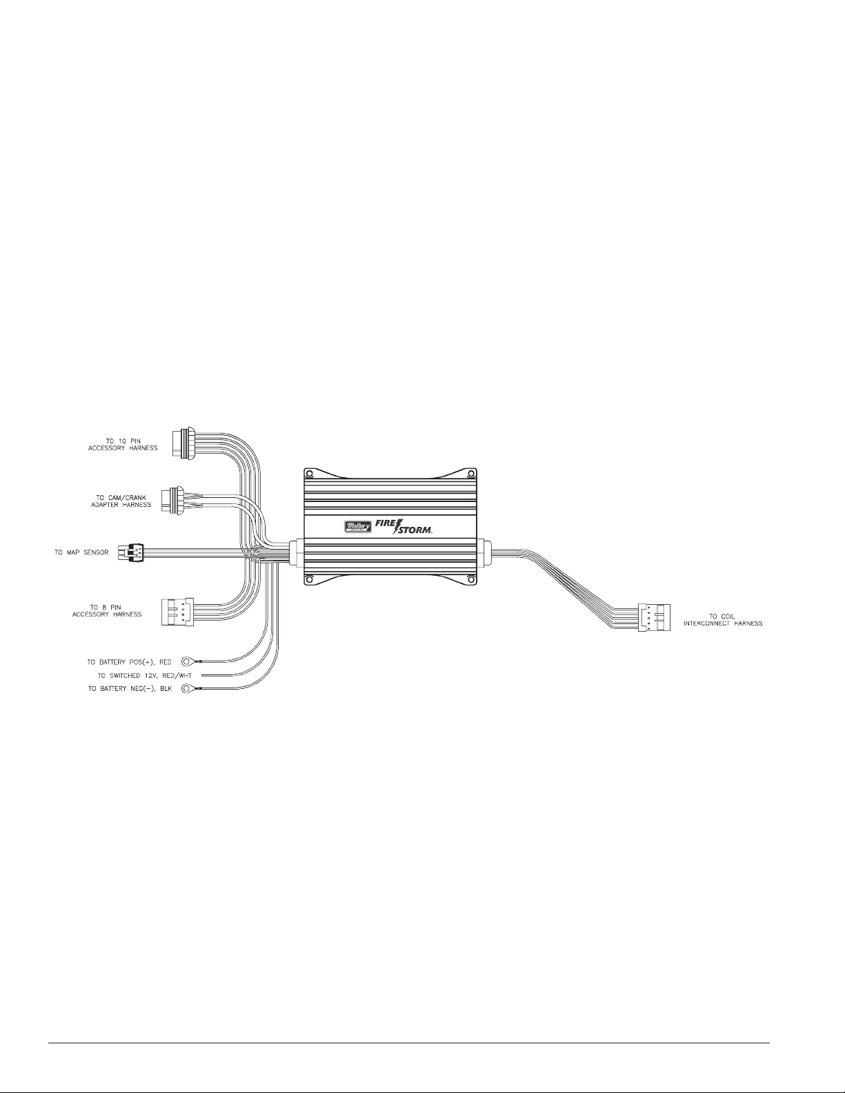
Refer to the wiring illustrations below for your specific application.
Connect the 12v switched ignition lead (labeled 12V SW) to a 12v
source that is live during crank and run. Consult your factory wiring
diagrams and verify with a test light. The Firestorm module must have
12v ignition power during cranking or the vehicle will not start.
Connect the VBAT lead directly to the battery positive terminal and the
PWR GND lead directly to the battery negative terminal.
Connect the 10 way coil out harness to the main coil harness. The main
coil harness is designed to connect to OEM GM Odd/Even coil harnesses, or Mallory Odd/Even coil harnesses. If you are using 140051
Firestorm coils, the GM or Mallory coil harnesses are a direct plug in.
Connect the dual sync sensor adapter harness (PN 77642 (GM) or
69000FS/FR - MULTI COIL
Power Leads
Vbat - Red 14 ga - battery power- connect directly to clean battery
positive terminal
Power Ground - Black 14 ga - battery ground - connect directly to
clean battery negative terminal
12v Sw Ign - Red/white 12 volt switched ignition power - connect to a
12v ignition source that has power during start and cranking
Coil Connections
10 way multi coil out - Connect to the included main coil harness
Main coil harness - connect harness leads marked even and odd to
their respective engine coil harnesses.
Shield ground - Connect to a good, clean chassis ground to minimize
EMI noise. Due to the high energy output of the Firestorm module, it
is very important that shield ground wires are well grounded to ensure
proper operation.
Trigger Inputs:
Connect the dual sync sensor to PN 77642 (GM) or 77643 (Ford) cam/
crank adapter harness 4 pin connector. The 8 pin connector connects
to the 8 pin cam/crank input connector of the Firestorm module.
Other Connections:
3 way MAP connector - connect to optional MAP sensor kit to expand
the tuning resolution of the Firestorm module based on engine load.
The Firestorm module defaults to an ignition curve that references
engine RPM only if a MAP sensor is not connected.
Accessory connectors:
There are 2 accessory connectors (8 and 10 pin) that can be used
to enable and control optional functions in the Firestorm ignition
module. Below is a listing of their individual functions and basic operating description. Refer to the ACCESSORY HARNESS LAYOUT
on page 6 or the software guide for information on configuring the
Firestorm software for proper operation of these functions.
Shift light - ground output to illuminate an external shift light. The
Firestorm module will ground this wire at the engine RPM you set in the
Mallory SparkMap software
www.malloryfirestorm.com
MIL - Malfunction indicator light - ground output to illuminate a MIL
light when a trouble code has been set. The trouble code can be read
with the Mallory SparkMap software.
2 Step - a 12v input on this line activates the 2 step rev limiter based
on settings in the Mallory SparkMap software.
3 Step - a 12v input on this line activates the 3 step rev limiter based
on settings in the Mallory SparkMap software.
Signal Ground - provides ground circuit for sensor inputs such as ECT,
IAT and TPS.
VSS - Vehicle Speed Sensor input.
ECT - Engine Coolant Temperature signal input
IAT - Intake Air Temperature signal input
Fan 1 - ground output to control a single electric fan relay based on
temperature settings in the Mallory SparkMap software.
Fan 2 - ground output to control a secondary electric fan relay based
MALLORY2
Page 3

on temperature settings in the Mallory SparkMap software.
PTS - not used in multi coil applications
Tach - Engine speed output for an external tachometer or as an RPM
input to another module (i.e. Gen 7/Thruster ECM in fuel only mode)
TPS - Throttle Position Sensor signal input
the Ignition Configuration Screen (Ctrl-I) and select the Ignition trigger
type from the drop down box and press F10 to send the change to the
Firestorm Module. This will set all parameters on this screen and save
the changes to memory in the Firestorm Module.
Navigate to the Engine Configuration Screen (Ctrl-E) and enable any
sensors you have installed to use as an input to Firestorm. These may
include:
UEGO - Universal Exhaust Gas Oxygen (wideband O2) sensor input
Data - ground input to trigger internal datalogging for applications
where datalogging without a laptop is required.
Aux 2 - Ground output. Use to ground a relay based on settings in the
Mallory SparkMap software ouput configuration screen
FP / Aux 3 - Ground output to control a fuel pump relay, or other auxiliary relay based on settings in the Mallory SparkMap software ouput
configuration screen
Switched 12v Out - 12v output at key on to provide power to other
modules.
ROUTING WIRES
Route all wires away from heat sources, sharp edges, and moving
objects. Route the trigger wires separate from the other wires and spark
plug wires. If possible, route them along a ground plane, such as the
block or firewall, which creates an electrical shield. The magnetic pickup
wires should be routed separately and twisted together to help reduce
extraneous interference. For best results use Shielded Ground Cable.
WARNING: The Firestorm Ignition Control Module is a capacitive discharge ignition. High voltage is present at the coil primary
terminals. Do not touch these terminals or connect test equipment
to them.
PRESTART CHECKLIST
• The small red/white wire is connected to a switched 12 volt source,
such as the ignition key. This wire must be hot in crank and run positions.
• Power leads are connected directly to the battery positive and negative terminals.
MAP -manifold pressure sensor
TPS- throttle position sensor
ECT - engine coolant temp sensor
IAT- intake air temp sensor
HEGO - wideband a/f ratio sensor
Set rev limits based on your application requirements.
If Firestorm fan control is used, set fan on and off temps based on your
application requirements.
Press “Send all to ECM” to save changes to the Firestorm module.
Press F3 to navigate to the Base ignition advance table. This table is
where ignition timing tuning for maximum performance is done. This
map is pre loaded with values that are a good starting point. Changes
to this table should be made to achieve maximum torque on an engine
/ chassis dyno, or maximum speed on the track without detonation,
and under controlled conditions. If you are not comfortable or familiar
with the tuning process, contact Mallory Technical Service for a recommendation to an authorized Mallory tuning dealer in your area.
TROUBLESHOOTING
This section offers several tests and checks you can perform to ensure
proper installation and operation of the Firestorm Ignition Control
Module. If you experience a problem with your Firestorm, first check
for proper installation and poor connections. You can eliminate many
problems by checking these items. If you have any questions concerning your Firestorm Ignition Control Module contact the MALLORY
Technical Service Department at 216-688-8300 Monday through
Friday, 8:00 am to 5:00 pm Eastern time.
Misses and InterMittent Problems
Most common causes include a coil or plug wire failure and arcing
from the boot plug.Perform the following checks:
• If you’re not using an alternator, the battery should be connected and
fully charged.
• The engine MUST be equipped with at least one ground strap to the
chassis.
Installing Mallory SparkMap Software and programming the module for first use.
Install the Mallory SparkMap software from the CD included in the
kit. Connect the included serial communication cable to your PC. It
may be necessary to use a USB to serial adapter if your PC is not
equipped with a serial port. Turn the ignition key on and select “Online
to Firestorm”. If you are using a USB to serial adapter, you will need to
determine which port your computer is using for your adapter. This can
be found in your PC device manager under “Ports”. Device manager
can be found under My Computer / Properties. The details of how to
access it can vary slightly depending on your operating system. If you
need assistance with this, contact the MALLORY Technical Service
Department at 216-688-8300 Monday through Friday, 8:00 am to 5:00
pm Eastern time.
Help for any parameter in the Mallory SparkMap software, can be accessed by clicking on the parameter name and pressing F1.
Once you are online with the module the “Comm Rx” light will be
flashing on the main screen, and the information bar at the bottom of
the screen will display “Online, F9” in the lower left hand corner. Go to
• Inspect the plug wires at the coil and at the spark plug for a tight
connection. Visually inspect for cuts, abrasions, or burns.
• Inspect the primary coil wire connections. WARNING: During cranking, or while the engine is running, very high voltage will be present and
no test equipment should be connected. WARNING: Do not touch the
coil terminals during cranking or while the engine is running.
• Make sure that the battery is fully charged and the connections are
clean and tight. If you are not running an alternator, this is an imperative check. If the battery voltage drops below 10 volts during a race,
the Ignition Control Module output voltage will drop.
• Is the engine running lean? Inspect the spark plugs and the entire
fuel system.
• Check all wiring connections for corrosion or damage. Remember to
use proper connections followed by soldering, then seal the connections completely.
Checking for Spark
Verify that the LED lights in the cap of the dual sync sensor and on the
front of the firestorm module blink during cranking. Due to the high
voltage output of the Firestorm CD module it is recommended to
verify spark using a timing light during cranking. If the light flashes during cranking then current is being sent to the plug by the module.
MALLORY 3www.malloryfirestorm.com
Page 4

CARBURETED AND FUEL INJECTED INSTALLATION DIAGRAMS:
WITH DUAL SYNC SENSOR (CARB APPLICATIONS)
69000FS/FR - MULTI COIL
69000FS/FR - MULTI COIL
WITH DUAL SYNC SENSOR (FI APPLICATIONS)
If you encounter problems or if you need further
technical assistance, please call our technical
service line at (216)688-8300.
www.malloryfirestorm.com
MALLORY4
Page 5

69000FS/FR - MULTI COIL
MALLORY 5www.malloryfirestorm.com
Page 6

ACCESSORY HARNESS LAYOUT
MALLORY IGNITION IS A TRADEMARK OF PRESTOLITE PERFORMANCE
10601 Memphis Ave. #12, Cleveland, OH 44144
216.688.8300 FAX 216.688.8306
www.malloryfirestorm.com
FORM 69000FS/FR
Made in U.S.A.
Printed in U.S.A.
06/12
MALLORY6
 Loading...