

Page 1

INSTALLATION INSTRUCTIONS
®
WINDOW RPM ACTIVATED SWITCH
PART NO. 646
Parts Included in this kit:
1 RPM Activated Switch Part No. 646
1 U shaped crimp-on wire terminal
1 #6 x 1/4" sheet metal screw
2 Velcro strips
CONTENTS
General Information ...................................................................... 1
Mounting Procedure ..................................................................... 1
Wiring Procedure .......................................................................... 1
How to Set the Window RPM Switch ........................................... 2
Wiring Diagrams for the RPM Activated Switch
Connecting to a HYFIRE® IV .....................................................2
Connecting to a HYFIRE® VII ....................................................3
Connecting to relays with a HYFIRE® VII ................................ 3
Connecting to a Timing Retard ................................................ 4
Connecting to a Timing Control ............................................... 4
Connecting to a Light ............................................................... 4
Connecting to an Electric (Shifter) Solenoid .......................... 5
Connecting to a Nitrous System .............................................. 6
Connecting to a Nitrous System and Timing Retard ..............6
Shifnoid Warning ....................................................................... 7
GENERAL INFORMATION
The Mallory 646 Window RPM Switch is an RPM switch that is triggered
from the tach terminal available on most aftermarket performance ignitions.
It will not only activate at a particular RPM, but can also be set to deactivate at a second, higher, RPM. It can be used on 4-12 cylinder engines.
NOTE: The Mallory 646 CANNOT be triggered from points or electronic distributor. It must be triggered from a tach output terminal.
The 646 features two independent sets of switch contacts that switch other
devices on or off when the selected RPM is reached. These contacts
switch a maximum current of 5 amps. To switch more than 5 amps, you
must use the RPM Activated Switch output to drive a high current relay,
such as a horn or headlight (see illustrations).
NOTE: The switch contacts are NOT connected electrically. This
allows you to turn one circuit on and another off at the same RPM.
MOUNTING PROCEDURE
Step 1
Disconnect the battery () cable to cut power to the system.
Step 2
Mount the unit in an area away from hot engine components or extreme
heat, such as exhaust manifolds, and away from moving parts, such as fans,
belts, and linkages.
Step 3
Mount the unit using supplied Velcro strips.
FORM 1008 (REV. A) 01/02
WIRING PROCEDURE
Step 1
Connect the BLACK WIRE to engine or chassis ground. You can use the
supplied U shaped terminal and #6 x 1/4" sheet metal screws to make
this connection. If you are connecting the RPM Activated Switch to an
aftermarket ignition system such as a Mallory HYFIRE
grounding location that the ignition uses. See Figures 2-4, pages 2-3.
®
, use the same
Step 2
Connect the RED WIRE to a 12-volt power supply, such as the ignition
switch. You can use the same wire that provides power for your ignition
as long as a ballast resistor is not wired in series with it. NOTE: Do NOT
connect the RED WIRE to the coil (+) terminal. Connect it to the
wire coming directly from the ignition switch. If your vehicle is
equipped with loom resistance wire, you must provide an alternate
power connection to the red wire.
Step 3
The GREEN WIRE must be connected to the ignition system tach output.
When using a Mallory ignition system, connect the GREEN WIRE
to the TACH terminal. See Figures 2-4, pages 2 and 3.
When using an aftermarket ignition with a TACH output, connect
the GREEN WIRE to the TACH terminal. Check manufactures ignition instructions to find this location.
Other aftermarket ignitions Connect the GREEN WIRE to the ta-
chometer lead terminal. Check manufacturers ignition instructions
to find this location.
Step 4
To connect a device that you want to switch ON at the RPM setting
youve selected, such as a shift light, connect one ORANGE WIRE to the
device and the other ORANGE WIRE to a 12-volt power supply. Connect
the remaining wire from the device to a ground. See Figure 5, page 4.
Step 5
To connect a device that you want to switch OFF at the RPM setting youve
selected, such as a nitrous solenoid, connect one PURPLE WIRE to the
device and the other PURPLE WIRE to a 12-volt power supply. Connect
the remaining wire from the device to a ground.
Step 6
Secure all wires to prevent contact with extreme heat, sharp objects, or
moving devices, such as fans, belts, and linkages.
Step 7
Recheck all wires and connections to ensure that they are correct before
applying power.
Step 8
Reconnect the battery () terminal cable. Start engine and check operation
of the RPM Activated Switch.
1MALLORY TECHNICAL SUPPORT (775) 882-6600 [email protected]
Page 2
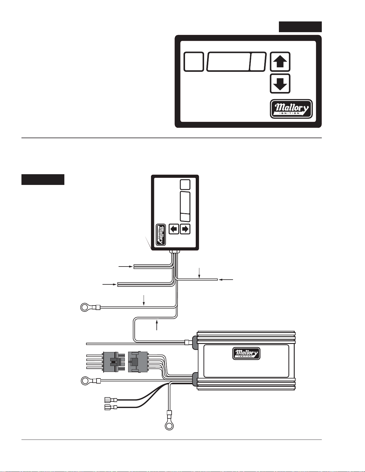
HOW TO SET THE WINDOW RPM SWITCH
C – CYLINDER SELECT
L – LOW RPM
H – HIGH RPM
DOWN
UP
WINDOW RPM SWITCH
P/N 646
MODE
VALUE
MODE
On the front panel there are three buttons and an LED display. The
MODE button cycles through the low RPM setting, the high RPM
setting, and the cylinder number select. The UP and DOWN
buttons move the RPM in 100 RPM increments in either of the RPM
modes, and select 3-12 in the cylinder select mode.
The RPM range is 1000 to 16000 in 100 RPM increments. The high
setting (H) must be at least 200 RPM higher than the low (L) setting
for the switch to operate properly. The display shows RPM in
hundreds (for example, 76 would be 7600 RPM.
Set the cylinder select mode to the number of cylinders your engine
has (4-cycle only).
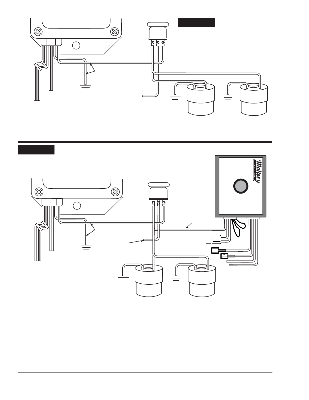
FIGURE 2
®
FIGURE 2
RPM ACTIVATED SWITCH WITH HYFIRE® IV
Connect ORANGE wires to a device
to be turned ON at a selected RPM
Connect PURPLE wires to a device to
be turned OFF at a selected RPM
To engine block or
chassis ground
To tachometer
BLACK
VALUE
MODE
MODE
UP
P/N 646
RED
C – CYLINDER SELECT
H – HIGH RPM
WINDOW RPM SWITCH
L – LOW RPM
DOWN
®
GREEN
Connect to 12 VOLT source
DO NOT connect to COIL +
Connect this harness according
to the instructions applicable to
the HYFIRE
®
being used.
To battery (+)
terminal
distributor or crank trigger
Used for magnetic pickup
®
HYFIRE® IV
IGNITION SYSTEM
To engine block or
chassis ground
MALLORY IGNITION 550 MALLORY WAY, CARSON CITY, NV 897012
Page 3
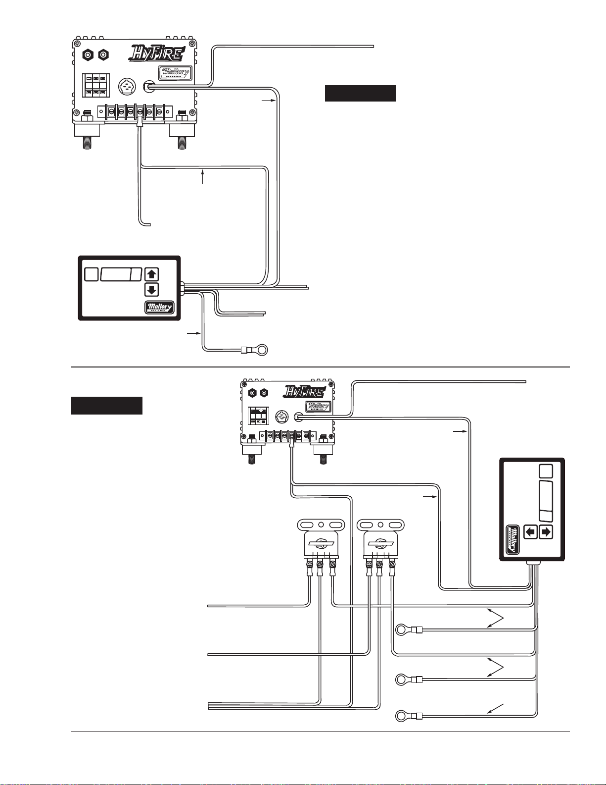
To tachometer
Connect ignition coil and distributor/trigger
wires according to the HYFIREÆ VII instructions
applicable to the distributor/trigger being used
0 7 5
DO NOT connect to coil (+) terminal
DO NOT connect to coil (+) terminal.
Connect this wire to a switched 12 volt
source. Switch must be capable of
switching all of the current from the
ignition and device(s).
The ignition may draw up to 1/2 amp.
Minimum of 18GA wire should be used.
P/N 646
MODE
VALUE
L ñ LOW RPM
H ñ HIGH RPM
C ñ CYLINDER SELECT
MODE
WINDOW RPM SWITCH
UP
DOWN
BLACK
BLACK
FIGURE 3
RPM ACTIVATED SWITCH WITH HYFIRE® VII
RED
ORANGE WIRES ñ
Connect to a device to be turned
ON at a selected RPM.
®
PURPLE WIRES ñ
Connect to a device to be turned OFF at a
selected RPM. NOTE: Relays are required if
device being switched draws more than 5 amps.
To engine block or
chassis ground
FIGURE 4
RPM ACTIVATED SWITCH AND
RELAYS WITH HYFIRE® VII
0 7 5
These relays are shown as examples
only. Other relays may be used, such
as Blue Streak Part No. RY-48
Connect this wire to a device to be
turned OFF at a selected RPM.
Connect the other wire from the device to
GROUND. NOTE: Relays are required if the
device being switch requires more than 5 amps.
Connect this wire to a device to be
turned ON at a selected RPM.
Connect the other wire from the device to
GROUND. NOTE: Relays are required if the
device being switch requires more than 5 amps.
DO NOT connect these wires to COIL (+) terminal
Connect these wires to a switched 12 volt source.
Switch must be capable of switching all of the
current from the ignition and devices.
DO NOT connect to COIL (+) terminal
STANDARD
STANDARD
Connect ignition coil and distributor/trigger wires
according to the HYFIRE
the distributor/trigger being used
Æ
VII instructions applicable to
GREEN
RED
To engine block or chassis ground
To engine block or chassis ground
To engine block or chassis ground
To tachometer
H ñ HIGH RPM
L ñ LOW RPM
VALUE
MODE
DOWN
MODE
UP
P/N 646
C ñ CYLINDER SELECT
WINDOW RPM SWITCH
®
PURPLE
ORANGE
BLACK
3MALLORY TECHNICAL SUPPORT (775) 882-6600 [email protected]
Page 4
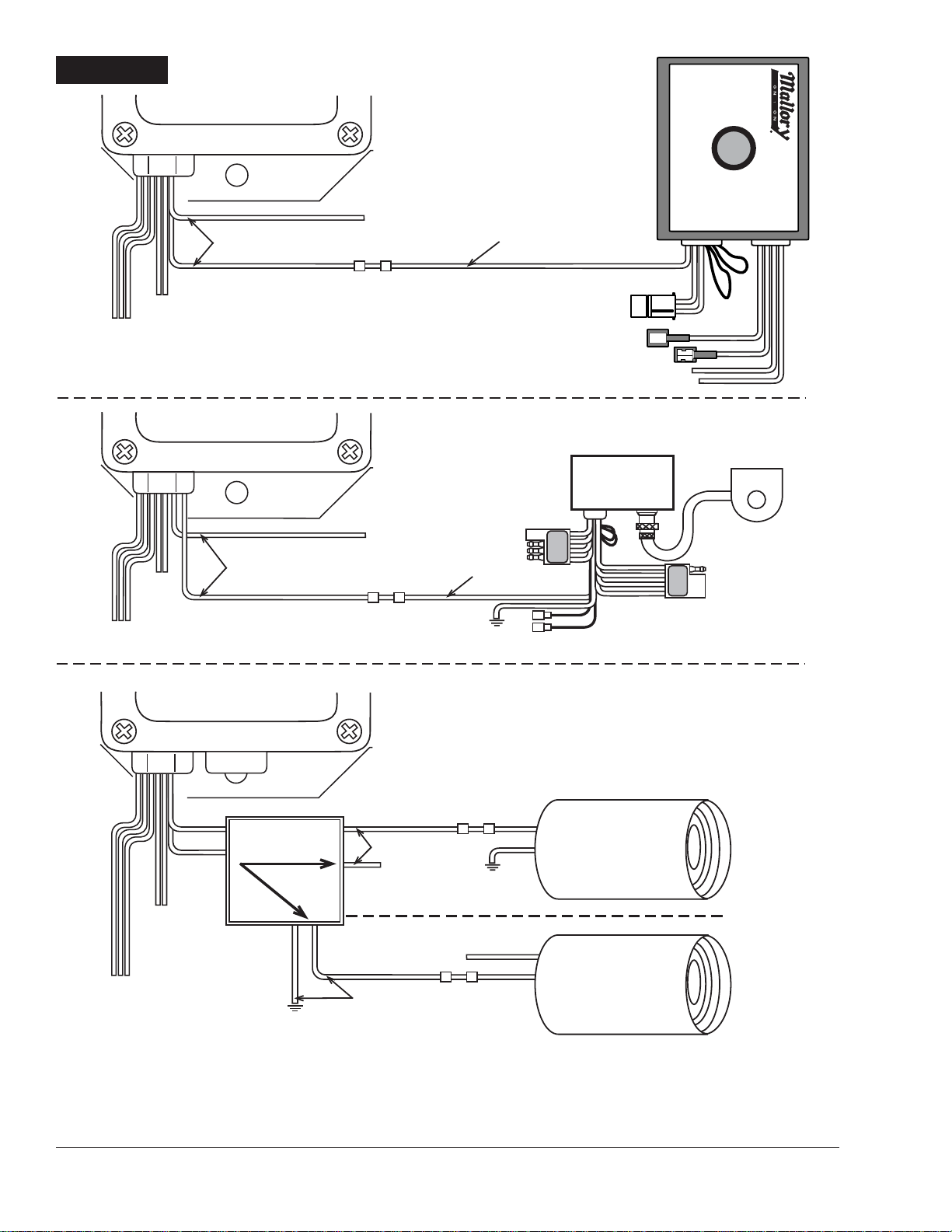
FIGURE 5
RED, GREEN AND BLACK
WIRES: SEE PAGES 5-12
TIMING RETARD ON AT RPM SETTING
PART NO. 646
TO 12V SOURCE
ORANGE WIRES (NORMALLY OPEN CLOSES/“ON” AT THE RPM SETTING)
PURPLE WIRES
(NOT USED)
PART NO. 646
ORANGE 18AWG
WIRE
IGNITION SYSTEM
PART NO. 631
HIGH SPEED RETARD
(ZERO)
1
3
0
5
7
9
1
1
5
1
1
3
618-1
REMOTE TIMING CONTROL
PART NO.
PURPLE
WIRES
(NOT
USED)
RED, GREEN AND BLACK
WIRES: SEE PAGES 5-12
PURPLE WIRES
(NOT USED)
RED, GREEN AND
BLACK WIRES: SEE
ORANGE WIRES (NORMALLY OPEN CLOSES/“ON” AT THE RPM SETTING)
PART NO. 646
ORANGE WIRES:
OR
TO 12V SOURCE
ORANGE WIRES
TO 12V SOURCE
TO 12V SOURCE
ORANGE WIRES
ORANGE 18AWG
WIRE
(#21)
NOTE: TO TURN LIGHTS “OFF” AT RPM SETTING - EXCHANGE THE ORANGE WIRES AND THE PURPLE WIRES.
MALLORY IGNITION 550 MALLORY WAY, CARSON CITY, NV 897014
Page 5
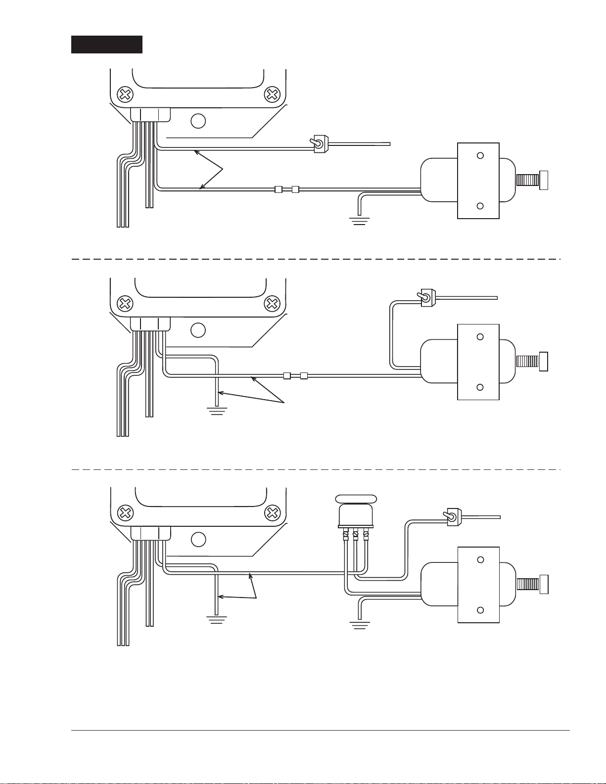
MANUAL SHIFTING: TURN
SWITCH “OFF”
TOGGLE SWITCH
PART NO. 26074
P ART NO . 646
P ART NO . 646
P ART NO . 646
TO 12V SOURCE
ORANGE OR PURPLE WIRES
RED, GREEN AND BLACK
WIRES: SEE PAGES 5-12
RED, GREEN AND BLACK
WIRES: SEE PAGES 5-12
RED, GREEN AND BLACK
WIRES: SEE PAGES 5-12
MANUAL SHIFTING: TURN SWITCH “OFF”
TOGGLE SWITCH
PART NO. 26074
TO 12V SOURCE
ORANGE OR PURPLE WIRES
MANUAL SHIFTING: TURN SWITCH “OFF”
TOGGLE SWITCH
TO 12V SOURCE
ORANGE OR PURPLE WIRES
HR - 106
1 3 5
USE ORANGE WIRES TO TURN
“ON” AT LOW RPM SETTING.
USE PURPLE WIRES TO TURN
“OFF” AT LOW RPM SETTING.
USE ORANGE WIRES TO TURN
“ON” AT LOW RPM SETTING.
USE PURPLE WIRES TO TURN
“OFF” AT LOW RPM SETTING.
USE ORANGE WIRES TO TURN
“ON” AT LOW RPM SETTING.
USE PURPLE WIRES TO TURN
“OFF” A
FIGURE 6
ELECTRIC (SHIFTER) SOLENOID
5MALLORY TECHNICAL SUPPORT (775) 882-6600 [email protected]
Page 6
P ART NO . 646
ORANGE WIRES
HR - 106
FIGURE 7
NITROUS SYSTEM ON
AT RPM SETTING
PURPLE WIRES
(NOT USED)
RED, GREEN AND BLACK
WIRES: SEE PAGES 5-12
TO 12V SOURCE:
“ON” ONLY WITH THE NITROUS
ARMING SYSTEM
NOTE: THE NITROUS SYSTEM WILL TURN "OFF" AT UPPER RPM SETTING.
FIGURE 8
NITROUS SYSTEM AND TIMING RETARD ON AT RPM SETTING
Y WITH THE NITROUS
P ART NO . 646
ORANGE WIRES
HR - 106
GAS
SOLENOID
ORANGE
18AWG WIRE
HIGH SPEED RETARD
(ZERO)
NITROUS
SOLENOID
1
3
0
5
7
9
1
1
5
1
1
3
PART NO.
618-1
TO 12V SOURCE:
“ON” ONL
PURPLE WIRES
(NOT USED)
RED, GREEN AND BLACK
WIRES: SEE PAGES 4-11
ARMING SYSTEM
GAS
SOLENOID
NOTE: THE NITROUS SYSTEM WILL TURN "OFF" AT UPPER RPM SETTING.
MALLORY IGNITION 550 MALLORY WAY, CARSON CITY, NV 897016
NITROUS
SOLENOID
Page 7
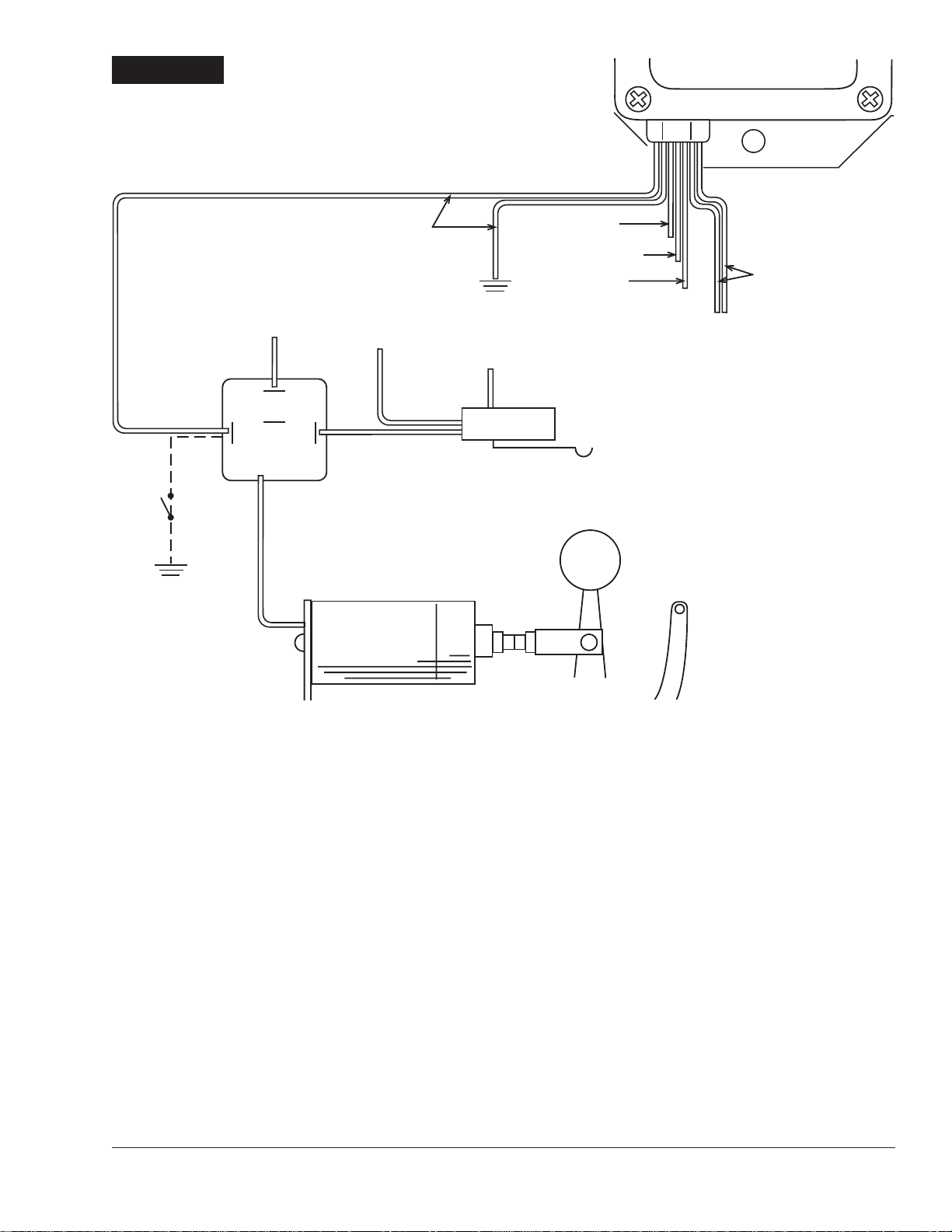
FIGURE 9
SHIFNOID WIRING FOR B&M RATCHET SHIFTER
W/SN5070 SOLENOID
PART NO. 646
OPTIONAL
SWITCH
TO 12V
87
87A
(NOT USED)
86 85
30
ORANGE WIRES
TO STARTER
SWITCH
SHIFNOID
INTERFACE RELAY
TO 12V
COMMON
NORMALLY OPEN
NORMALLY CLOSED
RED WIRE
12V IGN. SWITCH
GREEN WIRE
TACH TERMINAL
BLACK WIRE
GROUND
NEUTRAL SAFETY
B&M PRO
RATCHET SHIFTER
PURPLE WIRES
NOT USED
7MALLORY TECHNICAL SUPPORT (775) 882-6600 [email protected]
Page 8

MALLORY IS A DIVISION OF THE MR. GASKET PERFORMANCE GROUP
550 MALLORY WAY, CARSON CITY, NEVADA 89701
(775) 882-6600 FAX (775) 887-4326
www.mrgasket.com
MALLORY IGNITION 550 MALLORY WAY, CARSON CITY, NV 897018
FORM 1008
(REV. A) 01/02
Made in U.S.A.
Printed in U.S.A.
 Loading...