

Page 1

Hyre 6EZ and 6EZ RPML
Instruction Manual
Part#: 6855M, 6856M
Page 2

HYFIRE®6EZ and 6EZ RPML SERIES
ELECTRONIC IGNITION CONTROL
PART NOS. 6855M (6EZ) and 6856M (6EZ RPML)
PLEASE READ THESE INSTRUCTIONS COMPLETELY BEFORE STARTING THE INSTALLATION
INSTALLATION INSTRUCTIONS
FORM 1604 03/04
GENERAL INFORMATION
The features of the HYFIRE®6EZ and HYFIRE®6EZ RPML are
the same, with one exception: the HYFIRE®6EZ RPML includes
a single stage RPM limiter.You can set various RPM limits using
switches that are accessible through the rectangular cut-out in
the end bracket. See page 4 of this instruction form for more
information about the rev limiting features of the HYFIRE
®
6EZ RPML.
Battery
The HYFIRE
®
6EZ Series Ignition Control operates on any negative
ground, 12 volt electrical system with a distributor. It will also
work with 16 volt batteries and can withstand a momentary spike
of 24 volts in case of jump starts. This system delivers full voltage
with a supply of 10-18 volts, and operates with a supply voltage
as low as 8 volts. If your application does not use an alternator,
allow at least 15 amp/hour for every half hour of operation. If you
crank the engine with the same battery or other accessories, such
as an electric fuel or water pump, increase the amp/hour rating.
Coils
The ProMaster
®
e
Performance Coil will deliver optimum
performance with your HYFIRE®6EZ Ignition Control. The stock
coil on the vehicle is also retained.
NOTE: Do not install the HYFIRE®6EZ Ignition Control in any
vehicle that is originally equipped with a CD ignition control.
Spark Plugs and Wires
High quality, spiral wound wire and proper routing are essential
to the operation of the HYFIRE®6EZ Ignition Control. This type of
wire provides a good path for the spark to follow while minimizing
electromagnetic interference (EMI).
NOTE: Do not use solid core spark plug wires with the
HYFIRE®6EZ Ignition Control.
Routing
Wires should be routed away from sharp edges, moving objects,
and heat sources. Wires that are next to each other in the
engine’s firing order should be separated. For example, in a Chevy
V8 with a firing order of 1-8-4-3-6-5-7-2, the #5 and #7 cylinders
are positioned next to each other on the engine as well as in the
firing order. Voltage from the #5 wire could jump to the #7 wire.
This could cause detonation and engine damage. For added
protection against cross-fire, Mallory offers PRO SHIELD insulated
sleeving. Pro Shield is a glass woven, silicone coated protective
sleeve that slides over your plug wires. It also helps reduce
damage from heat and sharp objects.
MISCELLANEOUS INFORMATION
Sealing
Do not attempt to seal the HYFIRE®6EZ Ignition Control. All of the
circuits of a HYFIRE®6EZ receive a conformal coating of sealant
that protects the electronics from moisture. Sealing the HYFIRE
®
6EZ will not allow any moisture that seeps in through the
grommets to drain and may result in corrosion.
1 HYFIRE®6EZ Ignition Control
1 ProMaster e Performance Coil
1 Coil Wire Kit
8 #10 Sheet Metal Screws
4 10-32 X 7/8 Screws
4 10-32 nuts
2 Ring Terminals, Insulated
PARTS INCLUDED:
1
Mallory-Ignition.com
Page 3
mark the location of the mounting holes. Use a 1/8" drill bit to drill
the holes. Use the supplied self-tapping screws to mount the box.
The ProMaster
®
e
Performance Coil can be mounted in any
position. We recommend placing it within 24" of the distributor
for ease of wiring.
Welding
To avoid any damage to the HYFIRE
®
6EZ Ignition Control when
welding on the vehicle, disconnect the positive (red) and negative
(black) power cables of the HYFIRE®6EZ Ignition Control. It is also
a good idea to disconnect the tachometer ground wire
as well.
Distributor Cap and Rotor
We recommend installing a new distributor cap and rotor when
installing the HYFIRE®6EZ Ignition Control. Be sure the cap is
clean inside and out, especially the terminals and rotor tip. On
vehicles with smaller caps, it is possible for the air inside the cap
to become electrically charged causing crossfire which can result
in misfire. You can prevent this by drilling a couple of vent holes
in the cap. Drill the holes between terminals at rotor height, facing
away from the intake. If needed, place a small piece of screen
over the holes to act as a filter.
Hyfire®6EZ Diagnostic LED (Not available with rev limiting
ignition 6EZ RPML). On the end panel of your Hyfire 6EZ ignition
there is a small hole. Behind this hole is a red LED indicator.
The LED will flash when receiving a proper trigger signal from
the vehicle. If, after a normal power-up, the LED doesn’t flash
when cranking the engine, you should check your triggering
circuit for problems. If the LED flashes
when the engine is cranked, but there
is still no spark, the problem lies
somewhere else.
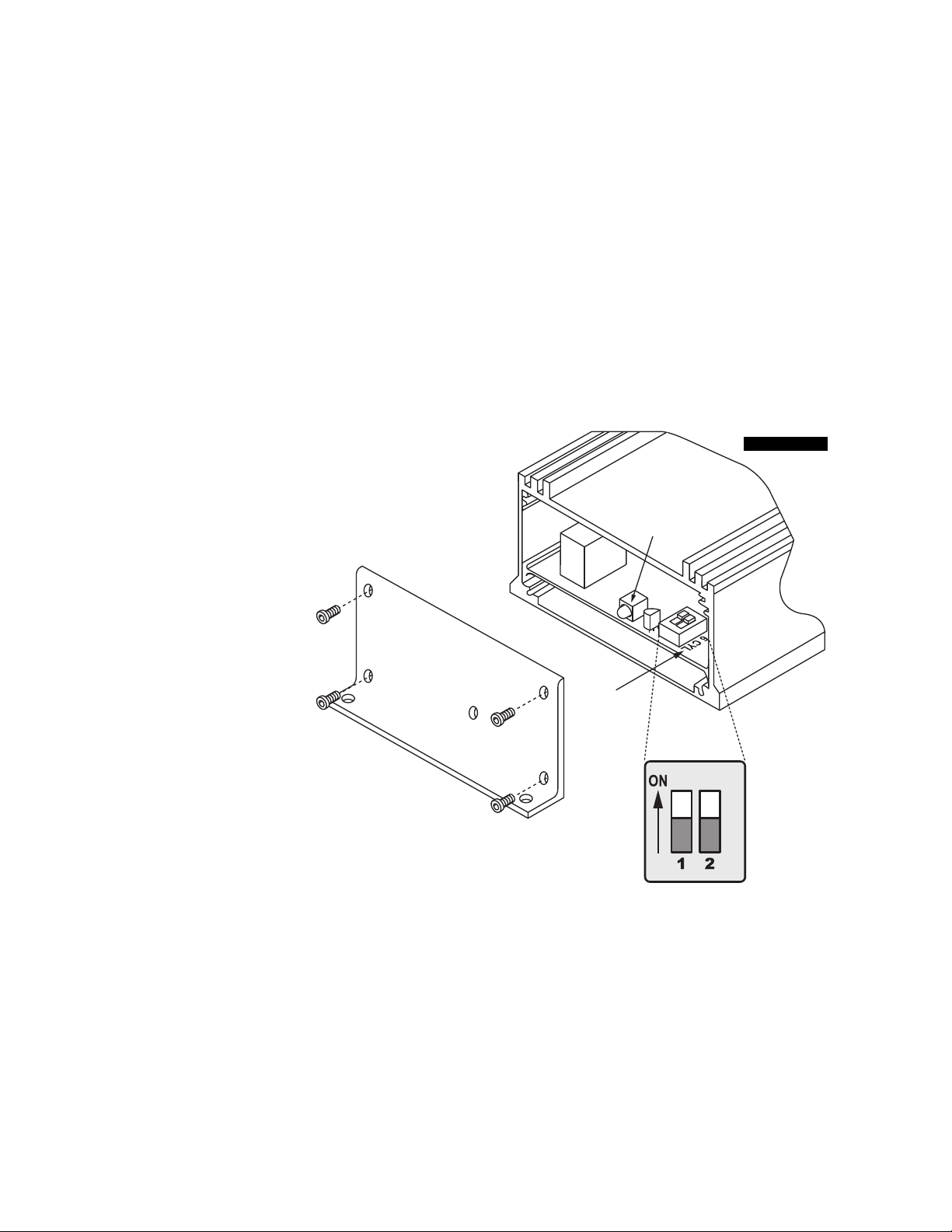
Hyfire®6EZ Cylinder Selection
Your HYFIRE®6EZ Ignition comes from
the factory set up for 8 cylinder
operation. If you want to use this
ignition with a 4 or 6 cylinder engine,
you must first remove the four screws
that hold the endplate with the LED hole. Once
the endplate is removed, you’ll see the end of the
circuit board. Look for the two-section switch. To select
4 cylinder mode, move the switch marked "1" to the "ON"
position. To select 6 cylinder mode, move the switch marked "2"
to the "ON" position. If both switches are "OFF", or both are
"ON", the ignition will run in the 8 cylinder mode. See Figure 1.
MOUNTING
The HYFIRE®6EZ Ignition Control can be mounted in any
position. If you mount it in the engine compartment, keep it
away from moving objects and heat sources. Do not mount
the unit in a closed area, such as the glovebox.When you find
a suitable location to mount the unit, make sure all wires of the
ignition reach their connections. Hold the ignition in place and
LABELS FOR
"CYLINDER SELECT"
ON CIRCUIT BOARD
DIAGNOSTIC
LED
2
Mallory-Ignition.com
Page 4
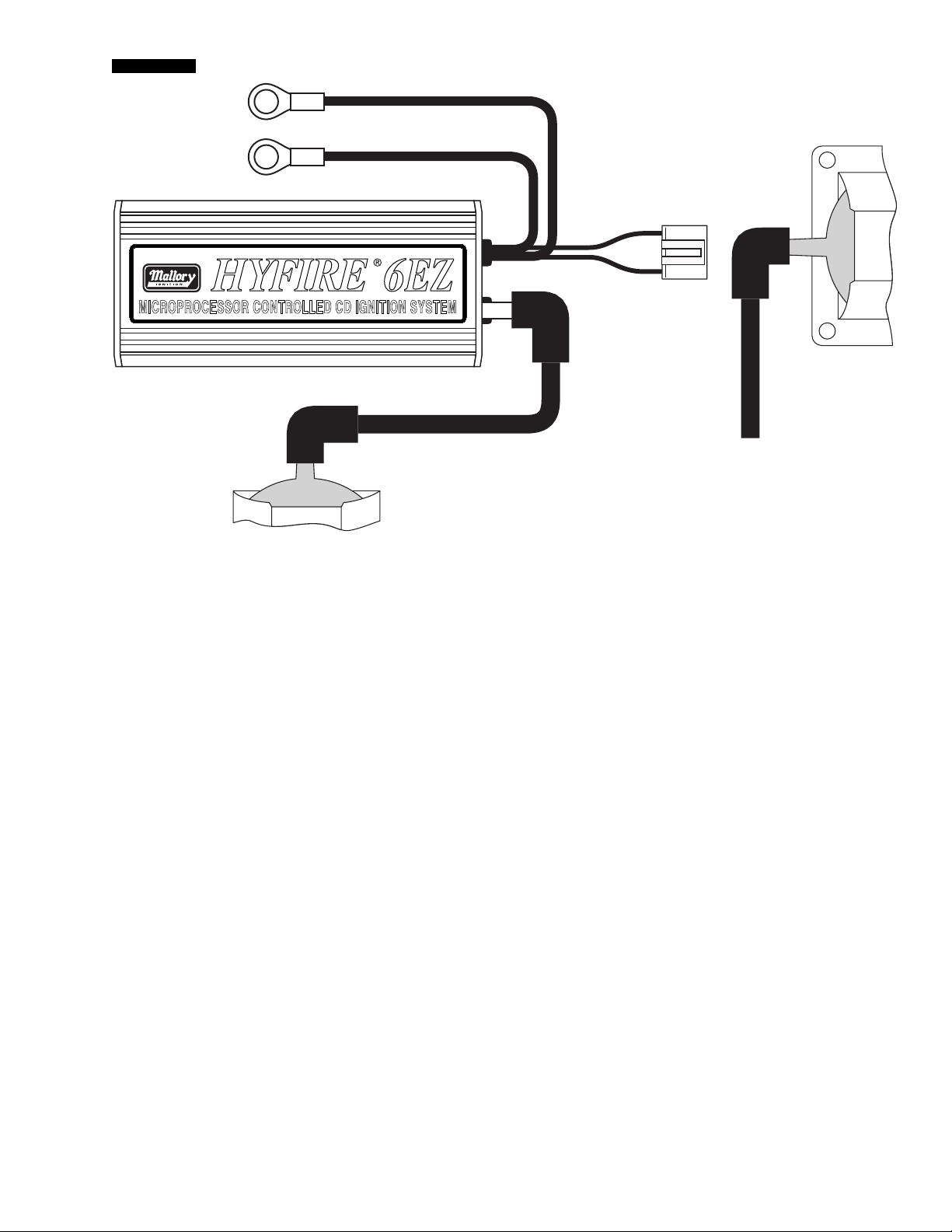
WIRING See Figure 2
Remove the factory coil wire and set it aside. Leave all other
wiring on the distributor and coil in place. Connect one of the 2
supplied coil wires from the factory coil tower to the high tension
tower on the end of the HYFIRE®6EZ Ignition Control.
Take the other supplied coil wire and connect it from the new
Mallory coil to the distributor.
Connect the Red wire from the harness to the battery positive
(+) terminal.
Connect the Black wire from the harness to the battery negative
(-) terminal.
Plug the harness connector into the matching connector on the
ignition control.
Note: All of the wires of the HYFIRE®6EZ Ignition Control may
be shortened as long as quality connectors are used or soldered in place.
BLACK (LARGE 14 GA)
TO BATTERY NEG (
-
)
RED (LARGE 14 GA)
TO BATTERY POS (
+
)
NEW COIL WIRE
COIL WIRE
STOCK COIL
NEW COIL
TO DISTRIBUTOR
®
PART No. 6855
WIRE FUNCTIONS
Power Leads
The two heavy gauge wires (14 gauge) that deliver battery voltage
to the ignition:
Heavy Red Connects directly to the battery positive (+)
terminal or to a positive battery junction. It
could also be connected to the positive side of
the starter solenoid.
NOTE: Never connect this
wire to the alternator.
Heavy Black Connects directly to the battery negative (-)
Orange/Black Plugs into the coil connector. These are the
only wires that make electrical contact with the
ProMaster
®
e
Performance Coil.
ROUTING WIRES
Route all wires away from heat sources, sharp edges, and moving
objects. Route the trigger wires separate from the other wires and
spark plug wires. If possible, route them along a ground plane,
such as the block or firewall, which creates an electrical shield.
The magnetic pickup wires should be routed separately and
twisted together to help reduce extraneous interference.
WARNING: The HYFIRE®6EZ Ignition Control is a capacitive
discharge ignition. High voltage is present at the coil primary
terminals. Do not touch these terminals or connect test
equipment to them.
Connector
3
Mallory-Ignition.com
Page 5

Rotary Switch Switch #1 Switch #1
Position DOWN UP
0 4,500 8,500
1 4,750 8,750
2 5,000 9,000
3 5,250 9,250
4 5,500 9,500
5 5,750 9,750
6 6,000 10,000
7 6,250 10,250
8 6,500 10,500
9 6,750 10,750
A 7,000 11,000
B 7,250 11,250
C 7,500 11,500
D 7,750 11,750
E 8,000 12,000
F 8,250 NO LIMIT
Number of
Cylinders Switch #2 Switch #3
4 UP Down
6 Down UP
8 Down Down
RPM Limiter Settings 6EZ RPML Only See Figure 3
Note the sticker attached to the end plate of the HYFIRE®6EZ
RPML. This sticker shows settings for number of cylinders and
RPM limits. In case the sticker becomes damaged or otherwise
unreadable, the settings are shown at right.
Setting Switch #4 Not used
PRESTART CHECKLIST
• The only wires connected to the new coil terminals should be
the orange connected to coil positive (+) and black connected
to coil negative (–).
• Power leads are connected directly to the battery positive and
negative terminals.
• Both coil wires are seated into place.
• The engine is equipped with at least one ground strap to the
chassis.
TROUBLESHOOTING
This section offers several tests and checks you can perform to
ensure proper installation and operation of the HYFIRE®6EZ
Ignition Control. If you experience a problem with your HYFIRE
®
6EZ, first check for proper installation and poor connections.
You can eliminate many problems by checking these items. If
you have any questions concerning your HYFIRE®6EZ Ignition
Control contact the Mallory Technical Service Department at
216.688.8300, Monday through Friday, 8:30 am to 5:30 pm
Eastern time.
Misses and Intermittent Problems
Experience has shown that if your engine is misfiring or hesitating
at higher RPM, it is usually not an ignition problem. Most common
causes include a coil or plug wire failure, arcing from the cap or
boot plug to ground or spark ionization inside the cap. Perform the
following checks:
FIGURE 3
• Inspect the plug wires at the cap and at the spark plug for a
tight connection. Visually inspect for cuts, abrasions, or burns.
The higher energy of the new ignition can create an arching
problem if the spark plug wires have deteriorated. This will
make the engine miss.
• Inspect the primary coil wire connections. Because the
HYFIRE®6EZ Ignition Control receives a direct 12 volt source
from the battery, there will not be any voltage at the coil
positive (+) terminal, even with the key turned on. During
cranking, or while the engine is running, very high voltage
will be present and no test equipment should be connected.
WARNING: Do not touch the coil terminals during cranking or
while the engine is running.
• Make sure that the battery is fully charged and the connections are clean and tight. If you are not running an alternator,
this is an imperative check. If the battery voltage drops below
10 volts during a race, the HYFIRE®6EZ Ignition Control output
voltage will drop.
• Is the engine running lean? Inspect the spark plugs and the
entire fuel system.
• Check all wiring connections for corrosion or damage.
Remember to use proper connections followed by soldering,
then seal the connections completely.
4
Mallory-Ignition.com
Page 6

CONTROL DE ARRANQUE ELECTRÓNICO
HYFIRE®SERIES 6
EZ
Y 6
EZ RPML
NÚMEROS DE PIEZAS 6855M (6EZ) y 6856M (6EZ RPML)
SÍRVASE LEER ESTAS INSTRUCCIONES COMPLETAMENTE ANTES DE INICIAR LA INSTALACIÓN
INSTRUCCIONES DE INSTALACIÓN
FORMULARIO 1604 03/04
1 control de arranque HYFIRE®6EZ
1 bobina ProMaster®Performance e Coil™
1 El Juego del Alambre del rollo
8 tornillos para hoja metálica Nº 10
4 tornillos 10-32 X 22,23 mm (7/8 de pulg.)
4 tuercas 10-32
2 terminales de anillo, aislados
PIEZAS INCLUIDAS:
INFORMACIÓN GENERAL
Las características del HYFIRE®6EZ y el HYFIRE®6EZ RPML son
idénticas, excepto que el HYFIRE®6EZ RPML incluye un circuito
limitador de RPM de una fase.
Se pueden establecer varios límites de RPM usando interruptores
que se acceden mediante la sección rectangular recortada en el
soporte terminal. Vea la página 4 de estas instrucciones para
obtener información adicional sobre las características de
limitación de revoluciones del HYFIRE®6EZ RPML.
Batería
El control de arranque serie HYFIRE®6EZ funciona en cualquier
sistema eléctrico de 12 voltios con tierra negativa que tenga
distribuidor. También funciona con baterías de 16 voltios y puede
soportar picos momentáneos de 24 voltios en caso de arranques
con conexión en puente provisional. Este sistema proporciona el
voltaje completo con suministro de 10 a 18 voltios y funciona con
un voltaje de suministro de hasta 8 voltios. Si su aplicación no
utiliza alternador, debe dejar por lo menos 15 amperios/hora por
cada media hora de funcionamiento. Si el motor gira con la
misma batería u otros accesorios, tales como una bomba
eléctrica de combustible o agua, aumente la capacidad de
amperios/hora.
Bobinas
La bobina ProMaster®Performance eCoil™ proporcionará el
rendimiento óptimo con el control de arranque HYFIRE®6EZ.
También se mantiene la bobina original del vehículo.
NOTA: No instale el control de arranque HYFIRE®6EZ en
ningún vehículo que originalmente viene equipado con un
control de arranque con descarga de condensador.
Bujías y cables
Los cables de alta calidad y bobinados en espiral, y el cableado
apropiado son fundamentales para el funcionamiento del control
de arranque HYFIRE®6EZ. Este tipo de cable proporciona una
buena ruta para la chispa y al mismo tiempo minimiza la
interferencia electromagnética (EMI, por sus siglas en ingles).
NOTA: No utilice cables para bujías con núcleos sólidos con
el control de arranque HYFIRE®6EZ.
Cableado
Los cables se deben colocar lejos de los bordes cortantes,
objetos en movimiento y fuentes de calor. Se deben separar los
cables que son consecutivos en el orden de encendido del motor.
Por ejemplo, en los motores Chevy V8 con orden de encendido
1-8-4-3-6-5-7-2, los cilindros 5 y 7 están ubicados uno al lado
del otro en el motor y en el orden de encendido. El voltaje
del cable 5 podría saltar al cable 7. Esto podría ocasionar
detonaciones y averías en el motor. Para obtener protección
adicional contra la interferencia, Mallory ofrece el forro aislado
PRO SHIELD. Pro Shield es un forro protector de tejido de vidrio y
revestido de silicón que se desliza sobre los cables de las bujías.
También ayuda a reducir los daños producidos por el calor y los
objetos cortantes.
INFORMACIÓN MISCELÁNEA
Sellado
No intente sellar el control de arranque HYFIRE®6EZ. Todos los
circuitos del HYFIRE®6EZ reciben un revestimiento conformado
de sellador que protege los componentes electrónicos de la
humedad. Al sellarse el HYFIRE®6EZ no permitirá que la
humedad que penetra por los ojales salga, lo que puede resultar
en corrosión.
5
Mallory-Ignition.com
Page 7

guantera. Cuando consiga una ubicación apropiada para montar
la unidad, asegúrese de que los cables del arranque alcancen las
conexiones. Sujete el arranque en su sitio y marque la posición
de los agujeros de montaje. Utilice una broca de 3,175 mm
(1/8 de pulg.) para taladrar los agujeros. Utilice los tornillos
autorroscantes suministrados para montar la caja.
La bobina Promaster
®
e
Coil™ se puede montar en cualquier
posición. Se recomienda colocar a un máximo de 61 cm
(24 pulg.) del distribuidor para facilitar el cableado.
Soldadura
Para evitar averiar el control de arranque HYFIRE
®
6EZ, al soldar
alguna pieza del vehículo, desconecte los cables de energía
positivo (rojo) y negativo (negro) del control de arranque HYFIRE
®
6EZ. También es aconsejable desconectar el cable de conexión a
tierra del tacómetro.
Tapa del distribuidor y rotor
Se recomienda la instalación de una nueva tapa del distribuidor y
rotor al instalar el control de arranque HYFIRE®6EZ. Asegúrese de
que la tapa esté limpia por dentro y por fuera, especialmente los
terminales y la punta del rotor. Es posible que en los vehículos
con tapas pequeñas, el aire dentro de éstas se cargue con
electricidad y ocasione interferencia que puede resultar en fallas
del encendido. Puede evitar que esto suceda taladrando dos
agujeros de ventilación en la tapa. Taladre los agujeros entre los
terminales a la altura del rotor, en el lado opuesto de la toma. Si
se requiere, ponga un trozo pequeño de malla sobre los agujeros
para que sirva de filtro.
El LED de diagnósticos Hyfire®6EZ (no está disponible con el
arranque con limitador de revoluciones 6EZ RPML). En el panel
terminal del arranque Hyfire 6EZ hay un agujero pequeño. Detrás
del agujero está un indicador LED rojo.
El LED parpadeará cuando reciba la
señal apropiada de disparador del
vehículo. Si luego del encendido
normal el LED no parpadea al girar el
motor, deberá verificar el circuito
disparador para ver si tiene problemas.
Si el LED parpadea cuando gira el
motor, pero no hay chispa, el problema
está en otro sitio.
Selección de cilindro para el
Hyfire®6EZ
El control de arranque HYFIRE®6EZ viene configurado de la fábrica para el funcionamiento con 8
cilindros. Si desea utilizar este arranque con un motor de 4 ó
6 cilindros, primero debe quitar los cuatro tornillos que sujetan la
placa terminal que tiene el agujero LED. Cuando quite la placa
terminal, verá el extremo de la tarjeta de circuito. Busque el
interruptor de dos secciones. Para seleccionar el modo de 4
cilindros, ponga el interruptor marcado “1” en la posición “ON”.
Para seleccionar el modo de 6 cilindros, ponga el interruptor
marcado “2” en la posición “ON”. Si ambos interruptores están
en la posición “OFF” o en “ON”, el arranque funcionará en el
modo de 8 cilindros. Consulte la figura 1.
MONTAJE
El control de arranque HYFIRE®6EZ se puede montar en
cualquier posición. Si lo monta en el compartimiento del motor,
manténgalo alejado de los objetos en movimiento y las fuentes
de calor. No monte la unidad en un sitio cerrado, como en la
LABELS FOR
"CYLINDER SELECT"
ON CIRCUIT BOARD
DIAGNOSTIC
LED
FIGURA 1
ETIQUETAS PARA
"SELECCIÓN DE CILINDRO"
EN LA TARJETA
DE CIRCUITOS
LED DE
DIAGNÓSTICOS
6
Mallory-Ignition.com
Page 8

CABLEADO (consulte la figura 2)
Quite el cable de la bobina instalada en fábrica y póngalo a un
lado. Deje todos los demás cables del distribuidor y la bobina en
su sitio. Conecte uno de los dos cables suministrados para la
bobina desde la torre de la bobina instalada en fábrica a la
torre de tensión alta en el extremo del control de arranque
HYFIRE®6EZ.
Conecte el otro cable suministrado para la bobina entre la nueva
bobina Mallory y el distribuidor.
Conecte el cable rojo entre el arnés y el terminal positivo (+)
de la batería.
Conecte el cable negro entre el arnés y el terminal negativo (-)
de la batería.
Enchufe el conector del arnés en el conector correspondiente
del control de arranque.
Nota: Todos los cables del control de arranque HYFIRE
®
6EZ se pueden acortar con tal que se utilicen o suelden
conectores de calidad en el sitio.
FUNCIONES DEL CABLEADO
Cables de energía
Los dos cables de calibre grueso (calibre 14) que trasmiten el
voltaje de la batería al arranque:
Rojo grueso Se conecta directamente al terminal positivo
(+) de la batería o a un empalme positivo de la
batería. También se podría conectar al lado
positivo del solenoide del arranque.
NOTA:
Nunca conecte este cable al alternador.
Negro grueso Se conecta directamente al terminal negativo
(-) de la batería
Naranja/negro Se conecta al conector de la bobina. Estos
son los únicos cables que hacen contacto
eléctrico con el de la bobina Mallory
ProMaster
®
e
Coil™.
CABLEADO
Coloque todos los cables lejos de las fuentes de calor, bordes
cortantes y objetos en movimiento. Separe los cables del
disparador de los otros cables, incluso los de las bujías. De ser
posible, colóquelos a lo largo de un plano conectado a tierra,
como el bloque del motor o la mampara cortafuegos, que crea un
blindaje eléctrico. Los cables del circuito de absorción magnética
deben colocarse por separado y se deben enroscar juntos para
ayudar a reducir la interferencia excedente.
ADVERTENCIA: El control de arranque HYFIRE®6EZ es un
arranque de descarga capacitiva. El voltaje alto se encuentra
en los terminales principales de la bobina. No toque estos
terminales ni conecte equipos de prueba en éstos.
BLACK (LARGE 14 GA)
TO BATTERY NEG (
-
)
RED (LARGE 14 GA)
TO BATTERY POS (
+
)
NEW COIL WIRE
COIL WIRE
STOCK COIL
NEW COIL
TO DISTRIBUTOR
®
PART No. 6855
conector
FIGURA 2
AL POSITIVO
DE LA BATERÍA
ROJO (GRUESO DE CALIBRE 14)
NEGRO (GRUESO DE CALIBRE 14)
CABLE DE LA
NUEVA BOBINA
NUEVA BOBINA
CABLE DE LA
BOBINA
BOBINA ORIGINAL
AL DISTRIBUIDOR
AL NEGATIVO
DE LA BATERÍA
7
Mallory-Ignition.com
Page 9

Valores del limitador de RPM 6EZ RPML
8
Mallory-Ignition.com
solamente vea la figura 3
Observe la calcomanía adherida a la placa terminal del HYFIRE
®
6EZ RPML. Esta calcomanía muestra los valores para el número
de cilindros y límites de RPM. En caso tal que la calcomanía se
dañe o no se pueda leer, los valores se muestran a continuación
a la derecha.
El valor del interruptor número 4 no se utiliza
FIGURA 3
LISTA DE VERIFICACIÓN DE PREARRANQUE
• Los únicos cables conectados a los terminales de la nueva
bobina deben ser el naranja al terminal positivo (+) y el negro
conectado al terminal negativo (-).
• Los cables de energía se conectan directamente a los
terminales positivo y negativo de la batería.
• Ambos cables de la bobina se asientan en su sitio.
• El motor tiene por lo menos una correa de conexión a tierra
conectada al chasis.
RESOLUCIÓN DE PROBLEMAS
Esta sección ofrece varias pruebas y verificaciones que puede
realizar para asegurar la instalación y funcionamiento apropiados
del control de arranque HYFIRE®6EZ. Si tiene problemas con el
HYFIRE®6EZ, primero verifique que la instalación esté bien hecha
o si hay conexiones indebidas.
Puede solucionar muchos problemas verificando estos
elementos. Si tiene preguntas sobre el control de arranque
HYFIRE®6EZ, póngase en contacto con el departamento de
servicio técnico de Mallory (Mallory Technical Service
Department), llamando al 216.688.8300, de lunes a viernes,
de 8.30 a 17.30 horas (huso horario del Este en EE.UU.).
Fallas y problemas intermitentes
La experiencia ha demostrado que si hay fallas del arranque del
motor o titubeo a RPM superiores, por lo general no es una falla
de arranque. Entre las causas más comunes se incluyen las
fallas de la bobina o cables de las bujías, arcos desde la tapa o
capuchón de la bujía, a tierra o ionización de la chispa dentro de
la tapa. Lleve a cabo las siguientes verificaciones:
Interruptor Interruptor Interruptor
giratorio número 1 número 1
Posición ABAJO ARRIBA
0 4,500 8,500
1 4,750 8,750
2 5,000 9,000
3 5,250 9,250
4 5,500 9,500
5 5,750 9,750
6 6,000 10,000
7 6,250 10,250
8 6,500 10,500
9 6,750 10,750
A 7,000 11,000
B 7,250 11,250
C 7,500 11,500
D 7,750 11,750
E 8,000 12,000
F 8,250 NO LIMIT
Número de Interruptor Interruptor
cilindros número 2 número 3
4 ARRIBA ABAJO
6 ABAJO ARRIBA
8 ABAJO ABAJO
• Revise los cables de las bujías en la tapa y en las bujías para
asegurarse que la conexión sea segura. Haga una inspección
ocular para ver si hay cortes, abrasiones o quemaduras. La
energía superior del nuevo arranque puede crear problemas de
arcos si hay deterioro en los cables de las bujías. Esto hará
que el motor falle.
• Inspeccione las conexiones del cable principal de la bobina.
Debido a que el control de arranque HYFIRE®6EZ recibe una
fuente directa de 12 voltios de la batería, no habrá voltaje en el
terminal positivo (+) de la bobina, aún con la llave encendida.
Durante el giro del motor o cuando éste esté encendido, habrá
un voltaje muy alto presente, y no se debe conectar ningún
equipo de pruebas.
ADVERTENCIA: No toque los terminales de la bobina cuando
el motor gire o mientras esté encendido.
• Asegúrese de que la batería esté totalmente cargada y que las
conexiones estén limpias y seguras. Si no utiliza un alternador,
esta verificación es obligatoria. Si el voltaje de la batería cae
por debajo de los 10 voltios durante una carrera, el voltaje de
salida del control de arranque HYFIRE®6EZ disminuirá.
• ¿El motor funciona con una proporción de gasolina?
Inspeccione las bujías y todo el sistema de combustible.
• Verifique todas las conexiones del cableado para ver si
muestran corrosión o están averiadas. Recuerde utilizar las
conexiones apropiadas seguidas por soldadura, luego selle las
conexiones por completo.
Page 10

HYFIRE®DE SÉRIES 6EZ ET 6EZ RPML
COMMANDE D’ALLUMAGE ÉLECTRONIQUE
PIÈCES Nos 6855M (6EZ) et 6856M (6EZ RPML)
VEUILLEZ LIRE TOUTES LES INSTRUCTIONS AVANT DE COMMENCER L’INSTALLATION
INSTRUCTIONS D’INSTALLATION
FORMULAIRE 1604 03/04
1 commande d’allumage HYFIRE®6EZ
1 bobine à haute performance ProMaster
®
e Coil
MC
1 la trousse de fil de bobine
8 vis pour tôle no10
4 vis 10-32 x 7/8
4 écrous 10-32
2 boucles de bornes, isolées
PIÈCES INCLUSES :
INFORMATIONS GÉNÉRALES
Les caractéristiques du HYFIRE®6EZ et du HYFIRE®6EZ RPML
sont identiques à une exception près : le HYFIRE®6EZ RPML
inclut un limiteur de régime mono-étage. Vous pouvez régler
plusieurs limites de régime à l’aide de commutateurs accessibles
par la fente rectangulaire du support d’extrémité. Voir la page 4
de ce livret d’instructions pour obtenir plus d’informations sur les
caractéristiques des limites de régime du HYFIRE®6EZ RPML.
Batterie
La commande d’allumage HYFIRE®de série 6EZ fonctionne sur
n’importe quel système électrique de 12 volts avec mise à la
terre négative équipé d’un distributeur. Il fonctionne également
avec des batteries de 16 volts et peut supporter une pointe
temporaire de 24 volts lors des démarrages d’appoint. Ce
système fournit une pleine tension avec une alimentation de 10 à
18 volts et fonctionne même avec une alimentation de tension
aussi faible que 8 volts. Si votre application n’utilise pas
d’alternateur, laisser au moins 15 ampères/heure pour chaque
demi-heure de fonctionnement. Lors d’un démarrage de moteur
avec la même batterie ou avec d’autres accessoires, comme
une alimentation électrique ou une pompe à carburant ou à eau,
augmenter la caractéristique nominale des ampères/heure.
Bobines
La bobine à haute performance ProMaster
®
e
CoilMCfournira une
performance optimale avec votre commande d’allumage HYFIRE
®
6EZ. La bobine standard du véhicule est également conservée.
REMARQUE : Ne pas installer la commande d’allumage
HYFIRE®6EZ dans un véhicule équipé à l’origine d’une
commande d’allumage à décharge capacitive (CD).
Bougies et câbles
Des câbles spiralés de grande qualité correctement acheminés
sont essentiels au fonctionnement de la commande d’allumage
HYFIRE®6EZ. Ce type de câble offre un bon circuit pour l’étincelle, tout en minimisant le brouillage électromagnétique (EMI).
REMARQUE : Ne pas utiliser de câbles de bougie à noyau
massif avec la commande d’allumage HYFIRE®6EZ.
Acheminement
Acheminer les câbles loin des rebords acérés, des pièces mobiles
et des sources de chaleur. Séparer les câbles adjacents l’un à
l’autre dans la séquence d’allumage du moteur. Par exemple,
dans une Chevy V8 avec une séquence d’allumage de 1-8-4-36-5-7-2, les cylindres 5 et 7 sont adjacents l’un à l’autre sur le
moteur comme dans la séquence d’allumage. La tension du câble
no5 pourrait être transférée au câble no7 et provoquer une
détonation qui endommagera le moteur. Mallory offre une gaine
isolée PRO SHIELD pour améliorer la protection contre une
injection à contre-courant. La gaine protectrice Pro Shield,
enduite de silicone et tissée en fibre de verre, se glisse sur les
câbles des bougies. Cette gaine aide également à réduire les
dommages causés par la chaleur ou les objets acérés.
INFORMATIONS DIVERSES
Étanchéité
Ne pas essayer de rendre étanche la commande d’allumage
HYFIRE®6EZ. Tous les circuits d’un HYFIRE®6EZ comportent
un enduit d’étanchéité conforme à la norme, qui protège les
éléments électroniques contre l’humidité. Le fait de rendre
étanche le HYFIRE®6EZ empêchera d’évacuer l’humidité qui
suinte par les oeillets et pourrait entraîner de la corrosion.
9
Mallory-Ignition.com
Page 11

Soudage
Pour éviter d’endommager la commande d’allumage HYFIRE
®
6EZ lors des soudures sur le véhicule, débrancher les câbles
positif (rouge) et négatif (noir) de la commande d’allumage
HYFIRE®6EZ. Il est également conseillé de débrancher le câble
de terre du compte-tours.
Chapeau du distributeur et rotor
Nous recommandons d’installer un nouveau chapeau de distributeur et un nouveau rotor lors de l’installation de la commande
d’allumage HYFIRE®6EZ. S’assurer que l’intérieur et l’extérieur
du chapeau est propre, en particulier les bornes et l’embout du
rotor. L’air à l’intérieur des plus petits chapeaux de certains
véhicules pourrait subir une charge électrique, provoquer une
injection à contre-courant et des ratés. Percer quelques trous de
ventilation dans le chapeau pour éviter ce problème. Percer les
trous entre les bornes, à la hauteur du rotor, du côté opposé à
l’alimentation. Le cas échéant, placer un petit morceau de grille
sur les trous, qui servira de filtre.
DÉL de diagnostic Hyfire®6EZ (non disponible avec limiteur
de révolution 6EZ RPML). Il y a un petit trou à l’extrémité du panneau de la commande d’allumage Hyfire 6EZ. La DÉL rouge est
située derrière ce trou. La DÉL clignote lorsqu’elle reçoit le signal
de déclenchement correct du véhicule.
Si la DÉL est activée normalement mais
ne clignote pas après un démarrage
habituel du moteur, vérifier le circuit de
déclenchement. Si la DÉL clignote au
démarrage du moteur, mais qu’il n’y a
pas d’étincelles, le problème est
ailleurs.
Sélection de cylindre
pour le Hyfire®6EZ
L’allumage HYFIRE®6EZ sort de l’usine réglé
pour les moteurs à 8 cylindres. Pour utiliser cet
allumage avec des moteurs à 4 ou 6 cylindres, enlever
d’abord les quatre vis qui maintiennent la plaque d’extrémité
avec le trou de DÉL. Une fois la plaque d’extrémité déposée,
l’extrémité de la carte du circuit imprimé est visible. Repérer
le commutateur à deux sections. Pour sélectionner le mode
4 cylindres, déplacer le commutateur marqué « 1 » à la position
« ON ». Pour sélectionner le mode 6 cylindres, déplacer le
commutateur marqué « 2 » à la position « ON ». Si les deux
commutateurs sont placés à « OFF » ou à « ON », l’allumage
fonctionne en mode 8 cylindres. Voir la Figure 1.
MONTAGE
La commande d’allumage HYFIRE®6EZ peut être montée dans
n’importe quelle position. Si elle est montée dans le compartiment moteur, la placer loin des pièces mobiles et des sources de
chaleur. Ne pas monter l’appareil dans un espace fermé, comme
une boîte à gants. Une fois identifié l’emplacement convenable
pour le montage de l’appareil, s’assurer que tous les câbles de
l’allumage atteignent leurs connexions. Maintenir l’allumage en
position et marquer l’emplacement des trous de montage. Utiliser
un foret de 3 mm (1/8 po) pour percer les trous. Utiliser les vis
autotaraudeuses fournies pour monter la boîte.
La bobine ProMaster
®
e
CoilMCpeut être montée dans n’importe
quelle position. Il est recommandé de la placer à moins de 60 cm
(24 po) du distributeur pour faciliter le câblage.
LABELS FOR
"CYLINDER SELECT"
ON CIRCUIT BOARD
DIAGNOSTIC
LED
FIGURE 1
ÉTIQUETTES DE
« SÉLECTION DES
CYLINDRES » SUR
LA CARTE DE
CIRCUIT IMPRIMÉ
DÉL DE
DIAGNOSTIC
10
Mallory-Ignition.com
Page 12

CÂBLAGE Voir la Figure 2
Déposer le câble de la bobine du fabricant et le mettre de côté.
Laisser en place tous les autres câbles du distributeur et de la
bobine. Connecter un des deux câbles de bobine fournis du
boîtier de bobine d’usine au chapeau haute tension à l’extrémité
de la commande d’allumage HYFIRE®6EZ.
Connecter l’autre câble de bobine fourni à la nouvelle bobine
Mallory et au distributeur.
Connecter le câble rouge du faisceau à la borne positive (+)
de la batterie.
Connecter le câble noir du faisceau à la borne négative (-)
de la batterie.
Brancher le connecteur de faisceau au connecteur correspondant
de la commande d’allumage.
Remarque : Tous les câbles de la commande d’allumage
HYFIRE®6EZ peuvent être raccourcis, en autant que des connecteurs de qualité sont utilisés ou soudés en place.
FONCTIONS DES CÂBLES
Conducteurs d’alimentation
Deux câbles de fort calibre (calibre 14) débitent la tension de la
batterie vers l’allumage :
Gros câble rouge Se connecte directement à la borne
positive (+) de la batterie ou à une jonction
positive de la batterie. Il peut également
être connecté au côté positif du solénoïde
du démarreur.
REMARQUE : Ne jamais
connecter ce câble à l’alternateur.
Gros câble noir Se connecte directement à la borne (-)
négative de la batterie
Orange/Noir Se branche dans le connecteur de la
bobine. Il s’agit des seuls câbles qui font
un contact de électrique avec la bobine
ProMaster
®
e
CoilMCde Mallory.
ACHEMINEMENT DES CÂBLES
Acheminer tous les câbles loin des sources de chaleur, des
rebords tranchants ou des pièces mobiles. Acheminer les câbles
déclencheurs séparément des autres câbles et des câbles de
bougies. Dans la mesure du possible, acheminer les câbles le
long d’une plaque de masse, comme le bloc ou le pare-feu, qui
crée une protection contre l’électricité. Les câbles de réglage
magnétique doivent être acheminés séparément et torsadés
ensemble pour aider à réduire le brouillage extérieur.
AVERTISSEMENT : La commande d’allumage HYFIRE®6EZ est
un allumage à décharge capacitive. Les bornes de la bobine
principale sont à haute tension. Ne pas toucher ces bornes
ou y brancher de l’équipement de test.
BLACK (LARGE 14 GA)
TO BATTERY NEG (
-
)
RED (LARGE 14 GA)
TO BATTERY POS (
+
)
NEW COIL WIRE
COIL WIRE
STOCK COIL
NEW COIL
TO DISTRIBUTOR
®
PART No. 6855
VERS LA BORNE POSITIVE
DE LA BATTERIE
VERS LA BORNE NÉGATIVE
DE LA BATTERIE
ROUGE (GROS, CAL. 14)
NOIR (GROS, CAL. 14)
NOUVEAU CÂBLE
DE BOBINE
BOBINE ORDINAIRE
CÂBLE DE BOBINE
VERS LE
DISTRIBUTEUR
NOUVELLE BOBINE
FIGURE 2
connecteur
11
Mallory-Ignition.com
Page 13

Réglages du limiteur de régime 6EZ RPML
12
Mallory-Ignition.com
seulement, voir la figure 3
Repérer l’étiquette attachée à la plaque d’extrémité du HYFIRE
®
EZ RPML. Cette étiquette indique les réglages correspondant au
nombre de cylindres et aux limites de régime. Si l’étiquette est
endommagée ou illisible, les réglages sont indiqués à droite.
Commutateur de réglage no4 – non utilisé
FIGURE 3
LISTE DE VÉRIFICATION AVANT DÉMARRAGE
• Seul le câble orange doit être connecté à la borne positive (+)
de la nouvelle bobine et seul le câble noir à la borne négative
(-) de la nouvelle bobine.
• Les câbles d’alimentation sont connectés directement aux
bornes positive et négative de la batterie.
• Les deux câbles de bobine sont logés en place.
• Le moteur est équipé d’au moins une bande de prise de terre
allant au châssis.
DÉPANNAGE
Cette section présente plusieurs tests et vérifications permettant
de vérifier si l’installation et le fonctionnement de la commande
d’allumage HYFIRE®6EZ sont corrects. En cas de problèmes avec
le HYFIRE®6EZ, vérifier d’abord l’installation et les
connexions.
Cette vérification permet d’éliminer de nombreux problèmes. Si
vous avez des questions sur la commande d’allumage HYFIRE
6EZ, contacter le département du Service technique de Mallory
au (216) 688-8300, du lundi au vendredi entre 8:30 h et 17:30 h,
heure de l’Est.
Ratés et problèmes intermittents
L’expérience a démontré que les ratés ou les hésitations d’un
moteur tournant à régime élevé, ne sont pas causés par un
problème d’allumage. Les causes les plus communes sont une
défaillance de bougie ou de bobine, la formation d’arc entre le
chapeau ou la douille de bougie vers la terre ou l’ionisation des
étincelles à l’intérieur du chapeau. Vérifier ce qui suit :
®
Commutateur Commutateur Commutateur
rotatif no 1 no 1
Position BAS HAUT
0 4,500 8,500
1 4,750 8,750
2 5,000 9,000
3 5,250 9,250
4 5,500 9,500
5 5,750 9,750
6 6,000 10,000
7 6,250 10,250
8 6,500 10,500
9 6,750 10,750
A 7,000 11,000
B 7,250 11,250
C 7,500 11,500
D 7,750 11,750
E 8,000 12,000
F 8,250 NO LIMIT
Nombre de Commutateur Commutateur
cylindres no 2 no 3
4 HAUT BAS
6 BAS HAUT
8 BAS BAS
• Inspecter les câbles des bougies au niveau du chapeau et de
la bougie pour voir si la connexion est serrée. Effectuer une
inspection visuelle pour détecter les câbles coupés, usés
ou brûlés. La plus grande puissance du nouvel allumage
peut créer un problème d’arc si les câbles de bougie sont
endommagés. Ceci produira des ratés.
• Inspecter les connexions de câble de la bobine principale.
Étant donné que la commande d’allumage HYFIRE
®
6EZ est alimentée en 12 volts directement par la batterie, la borne de la
bobine positive (+) ne recevra aucune tension, même lors de
l’activation du contact. Ne pas connecter d’équipement de test
pendant le démarrage ou avec un moteur qui tourne, car ils
produisent une forte tension.
AVERTISSEMENT : Ne pas toucher les bornes de la bobine
pendant le démarrage ou pendant le fonctionnement du
moteur.
• S’assurer que la batterie est à pleine charge et que les
connexions sont propres et bien serrées. Cette vérification est
obligatoire en l’absence d’un alternateur. Si la tension de la
batterie tombe sous la barre des 10 volts pendant une course,
la tension de sortie de la commande d’allumage HYFIRE®6EZ
chutera également.
• Le moteur tourne-t-il en sous régime? Inspecter les bougies et
tout le système d’alimentation d’essence.
• Vérifier toutes les connexions de câble pour y détecter de la
corrosion ou des dommages. Ne pas oublier d’utiliser les
connexions adéquates et correctement soudées, puis les
rendre complètement étanches.
Page 14

TROUBLESHOOTING GUIDE FOR
CAPACITIVE DISCHARGE
(CD) IGNITION SYSTEMS
Most CD boxes operate the same way, making for
common basic test procedures. Most CD ignition
boxes have two separate triggering circuits in them.
One is for a regular points driver signal, which is a
square wave, and one for 2 wire magnetic, which is
a sine wave, and the two have slightly different
test procedures.
Before beginning any testing, start with the basics.
Using your ignition instructions as a guide, recheck all
of the connections and terminals, and make sure the
wires are routed correctly and are free from abrasions
or other damage. Some ignitions also are equipped
with indicator lights that can check the power source
and some internal circuits.
IGNITION BOXES USING SINGLE WIRE POINTS
TYPE TRIGGERING
If the box powers up but does not fire the coil and the
white wire is being used as the trigger source, the
following tests should be done:
1. With the key off, remove the coil wire from
distributor cap and get it where you can jump a
spark to the block, with a gap of about 1/2 inch.
Separate the triggering wire that connects the box
and the distributor together, the wire colors will
differ between boxes and distributor combinations,
for example: MSD, Crane, ACCEL and Mallory
boxes are white. On the Mallory Hyfire I’s to IV’s
and the new Hyfire VI (6) P/N 685, this wire is green.
Refer to your ignition’s instruction sheet to confirm
the color of the wire.
2. Turn the ignition switch to the "ON" position. While
holding the coil wire close to the engine block, tap
the white wire to an engine ground. This will trigger
the box and should fire the coil, jumping a spark to
ground through the coil wire. If there is no spark
from the coil wire and no audible snap comes from
the box, the box is bad. If you hear a snap in the
box but no fire at the coil wire, then the coil or the
coil wire could be bad and they need to be tested.
3. If the test comes out positive and the box, coil and
coil wire are working, the distributor is either not
working or is improperly wired into the system and
the installation instructions should be revisited.
IGNITION BOXES USING TWO WIRE MAGNETIC
TYPE TRIGGERING
1. With the key off, remove the coil wire from the
distributor and position the wire so a spark can be
jumped to the block, with a gap of about 1/2 inch.
Disconnect the 2 magnetic wires from the box and
lay them aside. Next take a short piece of wire and
bend it in the shape of a "U". This wire will be used
to short the 2 wires of the magnetic connector on
the box together.
2. With the key in the "ON" position, the coil wire
where you can jump a spark to the engine block,
and using the "U" shaped wire you have made up,
short the two wires in the connector of the box
together and then disconnect the shorting wire.
3. ach time you disconnect the shorting wire the box
should fire the coil and should jump a spark to
ground. If the coil does not fire then either the
magnetic circuit in the box is inoperative or the coil
or coil wire are bad. Magnetic distributor pickups
are generally 400 to 650 ohms of resistance. If it is
a crank trigger, the pickup is rated at about 80
ohms resistance.
4. With any of the larger MSD, Crane, and Mallory 7
and 8 boxes the tests are similar. The difference is
that they have a terminal strip instead of a wire
harness but have the same two circuits in them
and test as follows.
5. To test the magnetic circuit in the box simply
disconnect the two wire from the "MAG + and
MAG –" terminal on the box. Connect a short piece
of wire to one of the terminals. With the key on and
coil wire ready to jump a spark to the block, rapidly
tap the other end of the short jumper wire to the
other magnetic terminal. The box should fire
the coil.
6. If the trigger is points or Unilite then disconnect the
distributor from the box. Connect a long piece of
wire to the "Points" terminal of the box. With the
key on, rapidly tap this wire to ground and the box
should fire the coil.
13
Mallory-Ignition.com
Page 15

7. If both of these tests prove out, then the problem is
either in the distributor, crank trigger, or the wiring
is incorrect.
TESTING THE COIL
NOTE: This test should only be done on "stock type"
coils. DO NOT try this test with "CD Only" coils, such
as the Mallory 28880 or ACCEL 140019 and 140010.
This test is also helpful in testing the coil when used
with just a distributor and you are having a "No
Spark" to the plugs condition. When doing this test
you must disconnect the distributor from the coil (-)
terminal, taking it out of the loop and allowing the test
to be done properly.
1. Disconnect the wires coming from the CD box to
the coil (+ and -) terminals and connect the ignition
switch 12 volts wire to the coil (+) terminal of
the coil.
2. Connect a 24" piece of wire to the coil (-) of
the coil.
3. Pull the coil wire out of the distributor cap and get
it to where you can jump a spark to ground with it.
4. Turn the ignition to the "ON" position.
5. Rapidly tap the 24" wire to ground. This will fire the
coil. You should get a 1/4” to 3/8" spark out of the
high voltage coil wire to ground. If you do then the
coil and coil wire are good and working.
6. If no spark to ground, change out the coil wire and
do the test again. If still no spark, the coil is bad
and needs to be replaced.
14
Mallory-Ignition.com
 Loading...