

Page 1

1MALLORY TECHNICAL SUPPORT (216) 688-8300 tech@mrgasket.com
HYFIRE®6A and 6AL SERIES
ELECTRONIC IGNITION CONTROL
PART NOS. 6852M (6-A) and 6853M (6-AL)
INSTALLATION INSTRUCTIONS
FORM 1522TL
GENERAL INFORMATION
The features of the HYFIRE®6-A and HYFIRE®6-AL are the same,
with one exception:
the HYFIRE®6-AL includes a single stage
RPM limiter
. You can set various RPM limits using switches that
are accessible through the rectangular cut-out in the end bracket.
See page 12 of this instruction form for more information about
the rev limiting features of the HYFIRE®6-AL.
Battery
The HYFIRE
®
6A Series Ignition Control operates on any negative
ground, 12 volt electrical system with a distributor. It will also work
with 16 volt batteries and can withstand a momentary spike of 24
volts in case of jump starts. This system delivers full voltage with
a supply of 10-18 volts, and operates with a supply voltage as low
as 8 volts.
If your application does not use an alternator, allow at least 15
amp/hour for every half hour of operation. If you crank the engine
with the same battery or other accessories, such as an electric
fuel or water pump, increase the amp/hour rating
Coils
For optimum performance with your HYFIRE
®
6A Ignition Control, we
recommend Mallory’s PROMASTER®Coil P/N 29440 or 30440.
Mallory’s PROMASTER®Coil P/N 29625 can also be used, as well as
most stock coils or aftermarket coils designed as stock replacements.
NOTE: Do not use Mallory’s PROMASTER®Coil P/N 28880.
Tachometers
The yellow wire on the HYFIRE®6A Ignition Control provides a
trigger signal for tachometers, shift lights, or other add-on RPM
activated devices. This wire produces a 12 volts square wave
signal with a 20% duty cycle.
Some vehicles with factory tachometers may require a tach
adapter to work with the HYFIRE®6A Ignition Control. If your GM
vehicle uses an inline filter, it may cause the tach to drop to zero on
acceleration. If this occurs, bypass the filter. For more information
on tachometers, see page 4.
Spark Plugs
Using the correct spark plug and heat range is important for
optimum performance. Because there are so many variables to
consider, we suggest starting with your engine manufacturer’s
spark plug recommendation. From there, you can experiment
with small changes in plug gap and heat range to obtain the best
performance from your engine. Use the chart at right as a starting
point. We also recommend non-resistor spark plugs.
Foreign Vehicles
Because of modern fuel injection systems, some foreign vehicles
may require a tachometer/fuel injection adapter to work with the
HYFIRE
®
6A Ignition Control.
NOTE: Do not install the HYFIRE®6A Ignition Control in any
vehicle that is originally equipped with a CD ignition control.
Spark Plugs and Wires
High quality, spiral wound wire and proper routing are essential to
the operation of the HYFIRE®6A Ignition Control. This type of wire
provides a good path for the spark to follow while minimizing
electromagnetic interference (EMI).
NOTE: Do not use solid core spark plug wires with the HYFIRE
®
6A Ignition Control.
Routing
Wires should be routed away from sharp edges, moving objects,
and heat sources. Wires that are next to each other in the engine’s
firing order should be separated. For example, in a Chevy V8
with a firing order of 1-8-4-3-6-5-7-2, the #5 and #7 cylinders
are positioned next to each other on the engine as well as in the
firing order. Voltage from the #5 wire could jump to the #7 wire.
This could cause detonation and engine damage.
For added protection against cross-fire, Mallory offers PRO SHIELD
insulated sleeving. Pro Shield is a glass woven, silicone coated
protective sleeve that slides over your plug wires. It also helps
reduce damage from heat and sharp objects.
1 HYFIRE
®
6A Ignition Control
4 #10 Sheet Metal Screws
2 Wire Ties
2 Ring Terminals, Insulated
1 1-amp/100 volt Diode
2 1/4" Tab Terminals
5 1/4" Male Disconnects
5 1/4" Female Disconnects
1 Rubber Grommet
2 Cable Clamps
1 Magnetic Pickup Extension
PARTS INCLUDED:
Page 2
MALLORY IGNITION www.malloryperformance.com2
area, such as the glovebox. When you find a suitable
location to mount the unit, make sure all wires of the ignition
reach their connections. Hold the ignition in place and mark the
location of the mounting holes. Use a 1/8" drill bit to drill the
holes. Use the supplied self-tapping screws to mount the box.
WIRING
Wire Length
All of the wires of the HYFIRE®6A Ignition Control may be
shortened as long as quality connectors are used or soldered
in place. To lengthen the wires, use one size larger gauge wire
(12 gauge for power leads, 16 gauge for all others). Use the
proper connectors to terminate all wires. All connections must
be soldered and sealed.
Grounds
A poor ground connection can cause many frustrating problems.
When a wire is specified to go to ground, connect it to the
chassis. Always connect a ground strap between the engine and
chassis. Connect any ground wires to a clean, paint-free metal
surface.
Ballast Resistor
If your vehicle has a ballast resistor in line with the coil wiring, it
is not necessary to bypass it. This is because the HYFIRE®6A
Ignition Control receives its main power directly from the battery.
MISCELLANEOUS INFORMATION
Sealing
Do not attempt to seal the HYFIRE®6A Ignition Control. All of the
circuits of a HYFIRE®6A receive a conformal coating of sealant
that protects the electronics from moisture. Sealing the HYFIRE
®
6A will not allow any moisture that seeps in through the
grommets to drain and may result in corrosion.
Welding
To avoid any damage to the HYFIRE®6A Ignition Control when
welding on the vehicle, disconnect the positive (red) and negative
(black) power cables of the HYFIRE®6A Ignition Control. It is also a
good idea to disconnect the tachometer ground wire as well.
Distributor Cap and Rotor
We recommend installing a new distributor cap and rotor when
installing the HYFIRE®6A Ignition Control. Be sure the cap is clean
inside and out, especially the terminals and rotor tip. On vehicles
with smaller caps, it is possible for the air inside the cap to become
electrically charged causing crossfire which can result in misfire.
You can prevent this by drilling a couple of vent holes in the cap.
Drill the holes between terminals at rotor height, facing away from
the intake. If needed, place a small piece of screen over the holes
to act as a filter.
HYFIRE®6A Diagnostic LED
On the end panel of your Hyfire 6A ignition there is a small hole.
Behind this hole is a red LED indicator.This serves two purposes:
when you first turn on the ignition switch, the LED will flash
rapidly 3 times. This indicates that the ignition system has power,
and that the microprocessor is running properly. In addition, the
LED will flash when receiving a proper trigger signal from the
vehicle. If, after a normal power-up, the LED doesn’t flash when
cranking the engine, you should check your triggering circuit for
problems. If the LED flashes when the
engine is cranked, but there is still no
spark, the problem lies somewhere else.
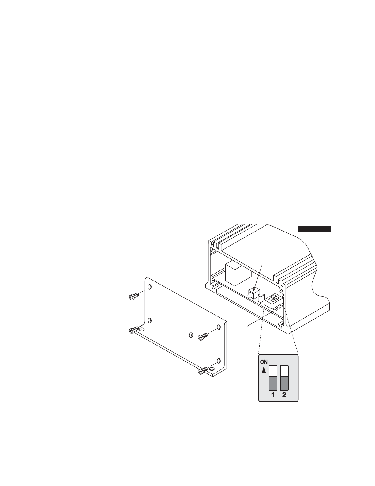
HYFIRE®6A Cylinder Selection
Your HYFIRE®6A Ignition comes from the
factory set up for 8 cylinder operation. If
you want to use this ignition with a 4 or 6
cylinder engine, you must first remove the
four screws that hold the endplate with the
LED hole. Once the endplate is removed,
you’ll see the end of the circuit board. Look
for the two-section switch. To select 4 cylinder
mode, move the switch marked “1” to the “ON”
position. To select 6 cylinder mode, move the switch
marked “2” to the “ON” position. If both switches are “OFF”,
or both are “ON”, the ignition will run in the 8 cylinder mode.
See Figure 1.
MOUNTING
The HYFIRE®6A Ignition Control can be mounted in any position. If
you mount it in the engine compartment, keep it away from moving objects and heat sources. Do not mount the unit in a closed
LABELS FOR
"CYLINDER SELECT"
ON CIRCUIT BOARD
DIAGNOSTIC
LED
FIGURE 1
Page 3
FROM HYFIRE® VIA
WHITE
BLACK
USING THE MAGNETIC
PICKUP WIRE TO TRIGGER
THE HYFIRE
®
VIA
USING THE WHITE
WIRE TO TRIGGER
THE HYFIRE
®
VIA
CONNECTS TO
PURPLE
BLACK
MAGNETIC PICKUP
PURPLE
GREEN
3MALLORY TECHNICAL SUPPORT (216) 688-8300 tech@mrgasket.com
COMMON COLORS FOR MAG PICKUP WIRES
Distributor Mag + Mag –
Mallory Crank Trigger Purple Green
Mallory Billet Competition Distributor,
Series Nos. 81 and 84 Orange Purple
Mallory COMP®9000 Series Nos. 96-99
Orange Purple
Mallory Harness P/N 29040 Red Black
MSD Orange/Black Violet/Black
MSD Crank Trigger Orange/Black Violet/Black
Ford Orange Purple
Accel 46/48000 Series Orange/Black Violet/Black
Accel 51/61000 Series Red Black
Chrysler Orange/White Black
WIRE FUNCTIONS
Power Leads
The two heavy gauge wires (14 gauge) that deliver battery voltage
to the ignition:
Heavy Red Connects directly to the battery positive (+)
terminal or to a positive battery junction. It could
also be connected to the positive side of the
starter solenoid.
NOTE: Never connect this wire
to the alternator.
Heavy Black Connects to frame or chassis ground.
Trigger and Coil Leads
Small Red Connects to a switched 12 volt source, such as
the ignition key.
Orange Connects to the positive (+) terminal of the coil.
NOTE: This is the only wire that makes
electrical contact with the coil positive (+)
terminal.
Small Black Connects to the negative (–) terminal of the coil
NOTE: This is the only wire that makes
electrical contact with the coil negative (–)
terminal.
Trigger Wires Either of two circuits will trigger the HYFIRE®6A
Ignition Control: a points circuit (white wire) or a
magnetic pickup circuit (violet and green wires).
NOTE: The two circuits will never be used
together.
White Connects to points, electronic ignition amplifier
output or to the green wire of a Mallory timing
accessory. When this wire is used, the magnetic
pickup connector is not used.
Violet/Green These wires are routed together in one harness
to form the magnetic pickup connector.The
connector plugs directly into a Mallory distributor
or crank trigger. It will also connect to factory
magnetic pickups or other aftermarket pickups.
The violet wire is positive (+) and the green is
negative (–). When these wires are used, the white
wire is not used. Consult the chart that shows the
polarity of other common magnetic pickups
Yellow Connects to the tachometer.
ROUTING WIRES
Route all wires away from heat sources, sharp edges, and moving
objects. Route the trigger wires separate from the other wires and
spark plug wires. If possible, route them along a ground plane, such
as the block or firewall, which creates an electrical shield. The
magnetic pickup wires should be routed separately and twisted
together to help reduce extraneous interference.
WARNING: The HYFIRE®6A Ignition Control is a capacitive
discharge ignition. High voltage is present at the coil primary
terminals. Do not touch these terminals or connect test
equipment to them.
PRESTART CHECKLIST
• The only wires connected to the coil terminals should be the
orange connected to coil positive (+) and black connected to
coil negative (–).
• The small red wire is connected to a switched 12 volts source,
such as the ignition key.
• Power leads are connected directly to the battery positive and
negative terminals.
• If you’re not using an alternator, the battery should be
connected and fully charged.
• The engine is equipped with at least one ground strap to the
chassis.
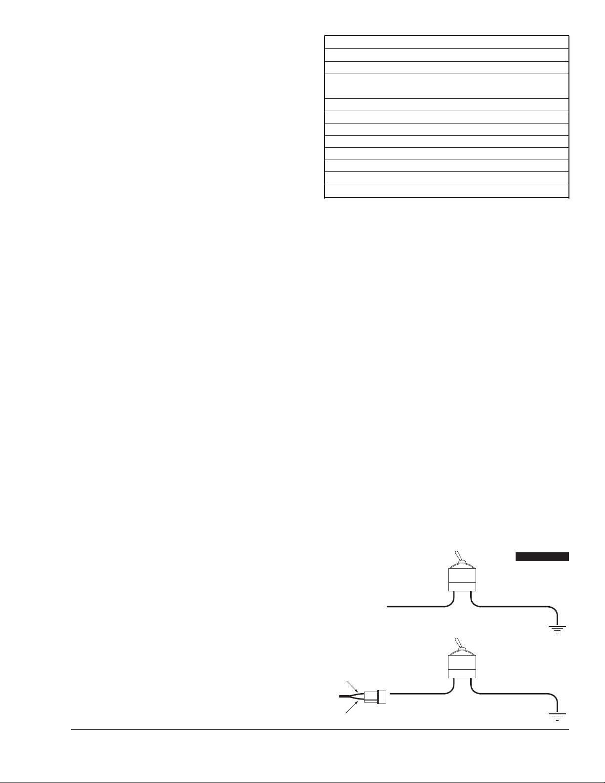
THEFT DETERRENT
The HYFIRE
®
6A Ignition Control provides an easy way to install a
theft deterrent kill switch. See Figure 2.
White Wire Trigger
When using the white wire to trigger the HYFIRE
®
6A Ignition
Control, install a switch to the white wire and the other side to
ground. When the white wire is grounded, the vehicle will crank
but will not start.
Magnetic Pickup Trigger
When using the mag pickup to trigger the HYFIRE
®
6A Ignition
Control, install a switch across the magnetic pickup violet wire to
ground. When the violet wire is grounded, the vehicle will crank
but will not start.
FIGURE 2
Page 4
FOR EARLY GM VEHICLES
ATTACH DIODE TO
#4 TERMINAL
FOR FORD VEHICLES
ATTACH DIODE TO
#1 TERMINAL
1A-100V DIODE
TO CHARGING LIGHT
SPLICE HERE
DELCOTRON
ALTERNATOR
1A-100V DIODE
TO CHARGING LIGHT
SPLICE HERE
SMALL RED
FROM HYFIRE
®
VIA
12 VOLT
IGNITION SWITCH
CHRYSLER DUAL
BALLAST RESISTOR
WHITE WIRE FROM
HYFIRE® VIA
FROM POINTS OR
AMPLIFIER
MALLORY IGNITION www.malloryperformance.com4
TACHOMETER COMPATIBILITY LIST
Aftermarket White Wire Magnetic Trigger
Tachometer Trigger Connector
Autogage 29074 29078
Autometer — —
Ford Motorsport — —
Moroso — —
Stewart 29074 29078
S.W. & Bi Torx — —
Sun 29074 29078
VDO 8910 29078
AMC (Jeep) 29074 29078
Chrysler 29074 29078
Ford (Before 1976) 29074 29078
Ford (After 1976) 29074 29078
GM Bypass in-line Bypass in-line
filter filter
Imports 29074 29078
TROUBLESHOOTING
This section offers several tests and checks you can perform to ensure
proper installation and operation of the HYFIRE®6A Ignition Control. If
you experience a problem with your HYFIRE®6A, first check for proper
installation and poor connections. You can eliminate many problems
by checking these items. If you have any questions concerning your
HYFIRE®6A Ignition Control contact the Mallory Technical Service
Department at 775-882-6600, Monday through Friday, 8:00 am to
5:00 pm Pacific time.
Tach/Fuel Adapters
If your tachometer does not operate correctly, you probably need a
Mallory tach adapter. Consult the Tachometer Compatibility List at
right for common tachometers and compatible tach adapters.
No-Run on Foreign Vehicles
Some foreign vehicles with fuel injection systems may require a
tachometer/fuel injection adapter to run with the HYFIRE
®
6A Ignition
Control. Often, the same trigger source is used to operate an ignition,
tachometer, and fuel injection. This results in a voltage signal that is
too low to trigger the fuel injection. A tach/fuel injection adapter will
usually solve this problem.
Inoperative Tachometers
If your tachometer fails to operate with the HYFIRE
®
6A installed, you
may need a Mallory tach adapter. Before purchasing a tach adapter,
try connecting your tachometer trigger wire to the yellow wire of the
HYFIRE®6A Ignition Control. This output produces a 12 volt, square
wave. If the tach still does not operate, you will need a tach adapter.
Two different tach adapters are available:
PN 29078 If you are using the magnetic pickup connector (green
and violet wires) to trigger the HYFIRE®6A, you will
need this adapter.
PN 29074 If your tach was triggered from the coil negative
terminal (voltage trigger) and you are suing the white
wire to trigger the HYFIRE®6A, you will need this
adapter.
Ballast Resistor
If you have a current trigger tach (originally connected to coil (+)
positive) and use the white wire of the HYFIRE
®
6A for triggering, you
can purchase a Chrysler Dual Ballast Resistor (1973-76 applications).
Wire it as shown in Figure 3.
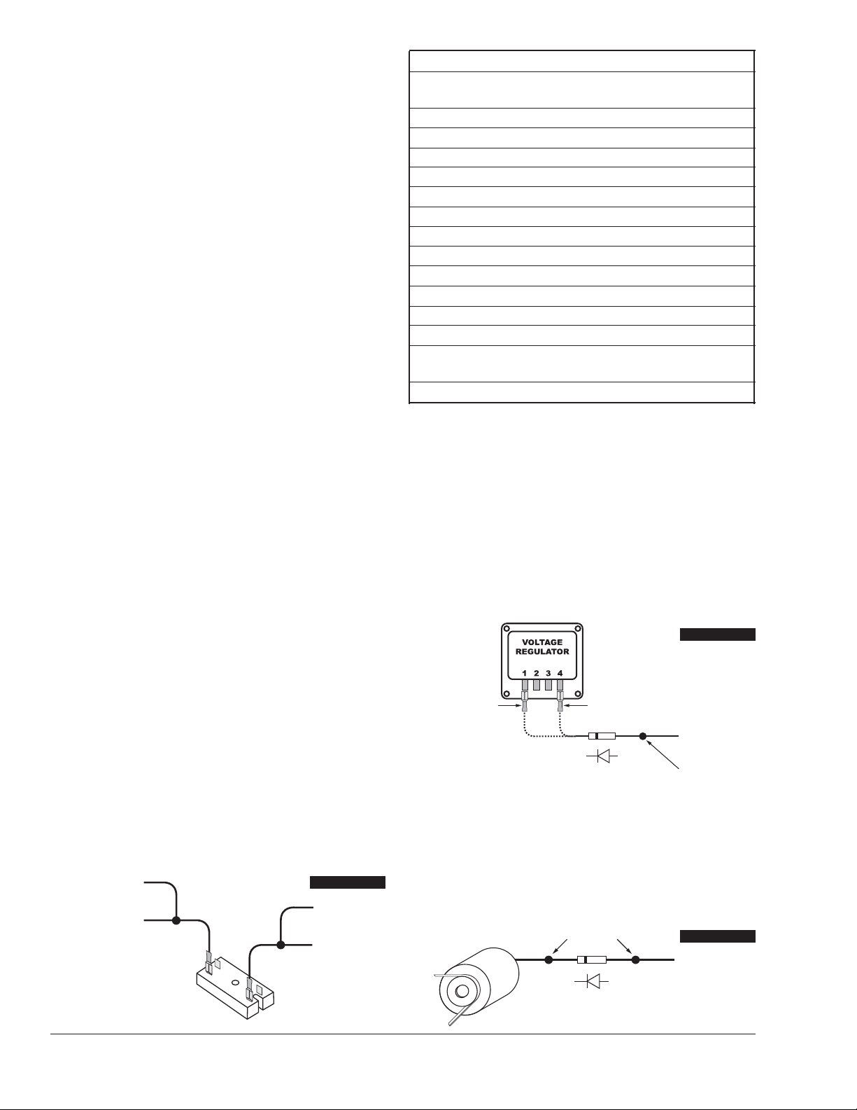
Engine Run-On
If your engine continues to run even when the ignition is turned off,
you are experiencing engine run-on. Usually, older vehicles with an
external voltage regulator are susceptible to this condition. Because
the HYFIRE
®
6A Ignition Control receives power directly from the
battery, it does not require much current to keep the unit energized.
If you are experiencing run-on, it is due to a small amount of voltage
going through the charging lamp indicator and feeding the small red
wire (even if the key is turned off).
GM 1973-83 with Delcotron Alternators
GM Delcotron alternators use an internal voltage regulator. Install the
diode inline on the smallest wire exiting the alternator (see Figure 5).
It is usually a brown wire.
Most other applications: To eliminate run-on, place a resistor in-line to
the HYFIRE
®
6A small red wire to keep voltage from leaking into the
HYFIRE
®
6A Ignition.
FIGURE 3
Early Ford and GM: To solve the run-on problem, a diode is supplied
with the HYFIRE®6A Ignition Control. By installing this diode in-line of
the wire that goes to the charging indicator, the voltage is blocked
from entering the HYFIRE®6A Ignition Control. Figure 4 shows the
proper diode installation for early Ford and GM vehicles.
NOTE: Diodes are used to allow voltage to flow only one way.
Make sure the diode is installed facing the proper direction, as
shown in Figure 4.
Ford: Install the diode inline to the wire going to the #1 terminal.
GM: Install the diode inline to the wire going to the #4 terminal.
FIGURE 4
FIGURE 5
Page 5
5MALLORY TECHNICAL SUPPORT (216) 688-8300 tech@mrgasket.com
Misses and Internittent Problems
Experience has shown that if your engine is misfiring or hesitating
at higher RPM, it is usually not an ignition problem. Most common
causes include a coil or plug wire failure, arcing from the cap or
boot plug to ground or spark ionization inside the cap. Perform the
following checks:
• Inspect the plug wires at the cap and at the spark plug for a tight
connection. Visually inspect for cuts, abrasions, or burns.
• Inspect the primary coil wire connections. Because the HYFIRE®6A
Ignition Control receives a direct 12 volt source from the battery,
there will not be any voltage at the coil positive (+) terminal, even
with the key turned on. During cranking, or while the engine is
running, very high voltage will be present and no test equipment
should be connected.
WARNING: Do not touch the coil terminals during cranking or
while the engine is running.
• Make sure that the battery is fully charged and the connections
are clean and tight. If you are not running an alternator, this is an
imperative check. If the battery voltage drops below 10 volts during
a race, the HYFIRE®6A Ignition Control output voltage will drop.
• Is the engine running lean? Inspect the spark plugs and the entire
fuel system.
• Check all wiring connections for corrosion or damage. Remember
to use proper connections followed by soldering, then seal the
connections completely.
If everything checks positive, use the procedure below to test the
ignition for spark. Mallory also offers an Ignition Tester (PN 28357) that
allows you to check the entire ignition system while it is installed in
the vehicle. This tool also checks operation of RPM limits, activated
switches, and shift lights.
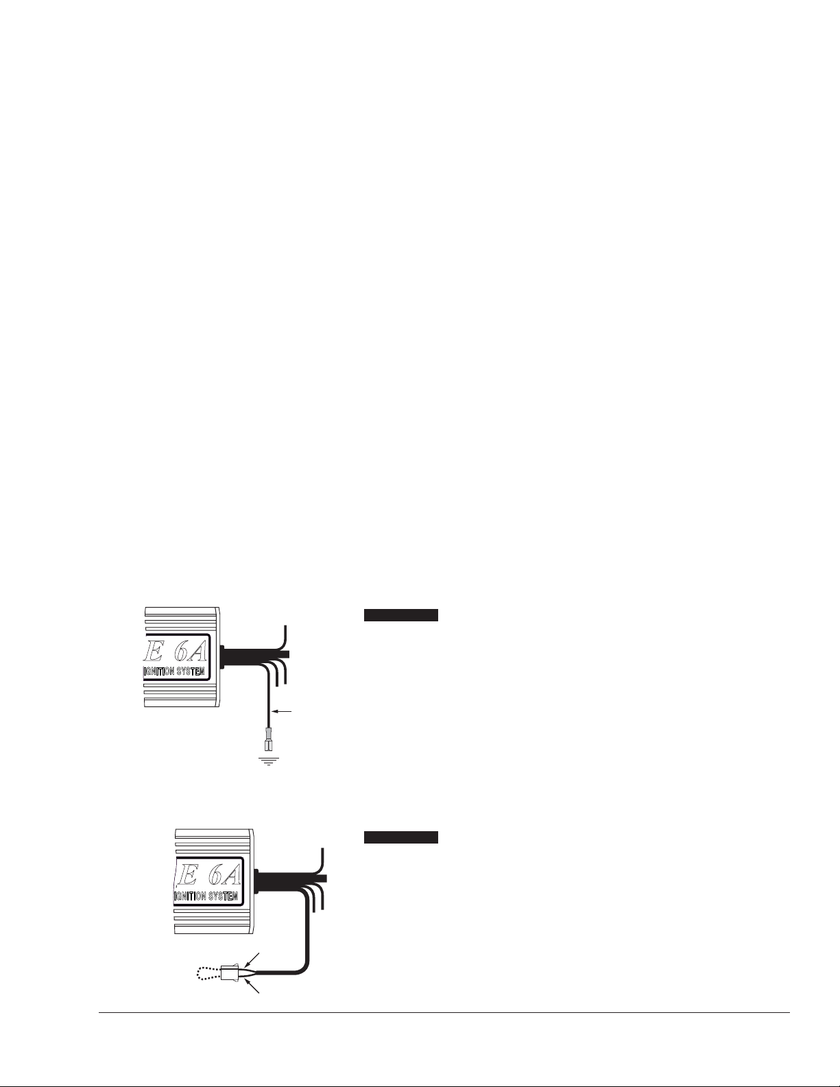
CHECKING FOR SPARK
If triggering the ignition with the white wire:
(See Figure 6)
1. Make sure the ignition switch is in the “OFF” position.
2. Remove the coil wire from the distributor cap and set the
terminal approximately 1/4" from ground.
3. Disconnect the HYFIRE
®
6A Ignition Control white wire from the
distributor’s points or ignition amplifier.
4. Turn the ignition to the “ON” position. Do not crank the engine.
5. Tap the white wire to ground several times. Each time you pull
the wire from ground, a spark should jump from the coil wire to
ground. If spark is present, the ignition is working properly. If
there is no spark, skip to Step 6 below.
If Triggering With the Magnetic Pickup:
(See Figure 7)
1. Make sure the ignition switch is in the OFF position.
2. Remove the coil wire from the distributor cap and set the
terminal approximately 1/4" from ground.
3. Disconnect the HYFIRE
®
6A Ignition Control magnetic pickup
wires from the distributor.
4. Turn the ignition to the ON position. Do not crank the engine.
5. With a small jumper wire, short the HYFIRE®6A Ignition Control
green and violet magnetic pickup wires together. Each time you
break this short, a spark should jump from the coil wire to
ground. If spark is present, the ignition is working properly. If
there is no spark skip to Step 6 below.
6. If there is no spark.
A. Inspect all of the wiring.
B. Substitute another coil and repeat the test. If there is now
spark, the coil is at fault.
C. If there is still no spark, check to make sure there is 12 volts
on the small red wire from the HYFIRE®6A Ignition Control
when the key is in the ON position. If 12 volts is not present,
find another switched 12 volts source and repeat the test.
D. If, after following the test procedures and inspecting all of
the wiring, there is still no spark, the HYFIRE®6A Ignition
Control is in need of repair. See the Warranty and Service
section for information.
JUMPER WIRE
GREEN
VIOLET
FIGURE 7
TO GROUND
WHITE
WIRE
FIGURE 6
The illustrations on the following pages show the
best way to install the HYFIRE
®
6A Ignition Control
on various applications. If you have any problems
or questions while installing this device on your
vehicle, contact the Mallory Technical Service
Department at (775) 882-6600, 8:00 AM to 5:00 PM
Pacific time, or email tech@mrgasket.com.
Page 6
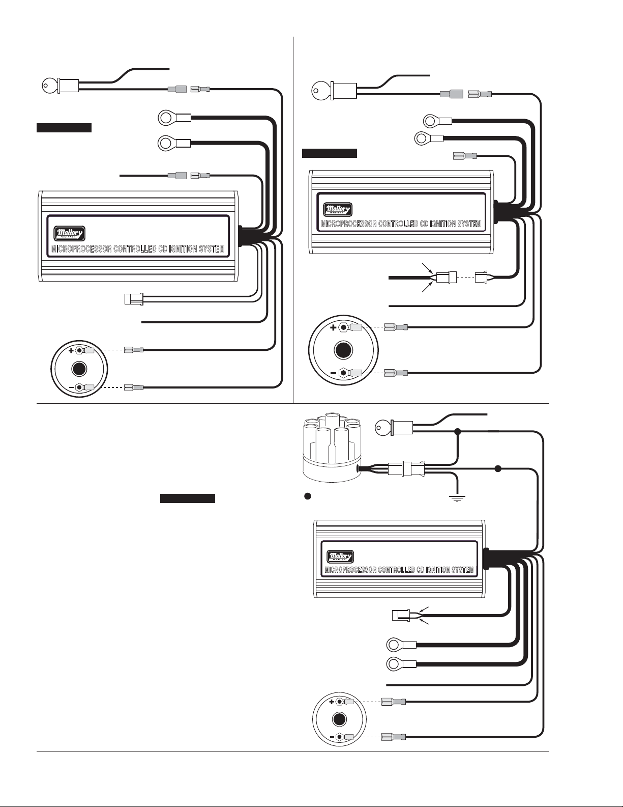
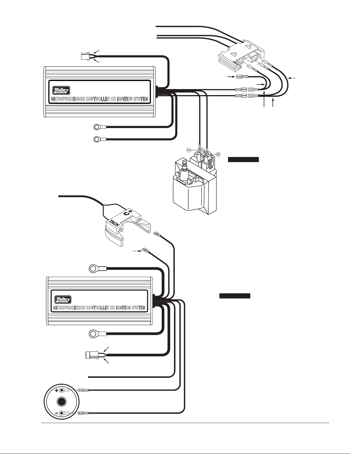
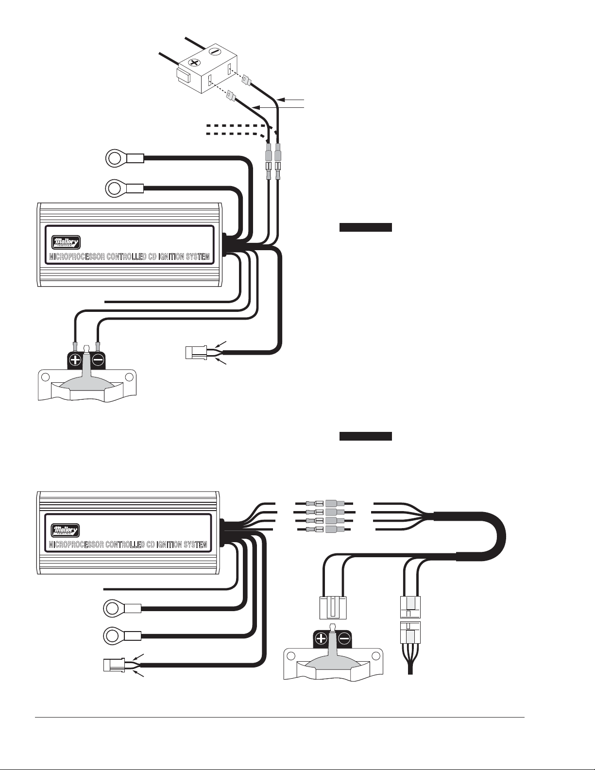
PART No. 6852
R
BLACK (SMALLER)
ORANGE
YELLOW
COIL
WHITE
GREEN
PURPLE
RED (SMALL 18 GA)
BLACK (LARGE 14 GA)
RED (LARGE 14 GA)
TO BATTERY NEG (
-
)
TO BATTERY POS (
+
)
ORIGINAL COIL (
+
)
IGNITION KEY
NOT USED
TO 12 VOLTS
TO TACHOMETER
FROM MAG PICK-UP DIST
OR CRANK TRIGGER
PART No. 6852
R
IGNITION KEY
TO 12 VOLTS
BLACK (SMALLER)
ORANGE
YELLOW
COIL
WHITEGREEN
BROWN
RED (SMALL 18 GA)
TO TACHOMETER
BLACK (LARGE 14 GA)
TO BATTERY NEG (
-
)
RED (LARGE 14 GA)
TO BATTERY POS (
+
)
RED
TO
ENGINE
CONNECT WIRES AT
THESE POINTS
NOT USED
GREEN
PURPLE
PART No. 6852
R
BLACK (SMALLER)
ORANGE
YELLOW
COIL
WHITE
Original coil wire from points
or electronic ignition amplifier
RED
BLACK (LARGER)
RED (LARGER)
TO BATTERY NEG (
-
)
TO BATTERY POS (
+
)
IGNITION KEY
TO 12 VOLTS
TO TACHOMETER
MAGNETIC PICK-UP
(NOT USED)
Originally connected to coil (+)
MALLORY IGNITION www.malloryperformance.com6
Installing the HYFIRE®6A with a Magnetic
Pickup Distributor or Crank Trigger
Installing the HYFIRE
®
6A with a
Mallory UNILITE
®
or Magnetic
Breakerless Distributor
Installing the HYFIRE®6A with a Points/Amplifier
Style Ignition
FIGURE 8
FIGURE 9
FIGURE 10
HHYYFFIIRREE 66AA
HHYYFFIIRREE 66AA
HHYYFFIIRREE 66AA
®
®
®
Page 7
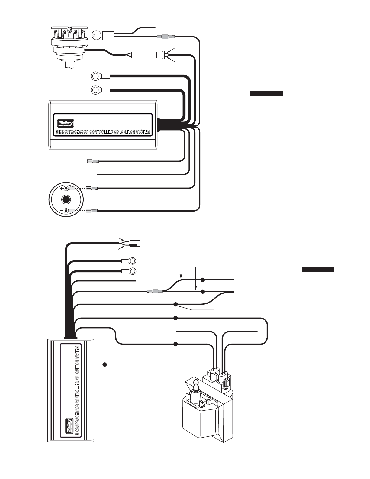
PART No. 6852
R
BLACK (SMALLER)
ORANGE
YELLOW
COIL
WHITE
NOT USED
REDORIGINAL COIL (+)
IGNITION KEY TO 12 VOLTS
TO TACHOMETER
RED (LARGE 14 GA)
TO BATTERY POS (
+
)
BLACK (LARGE 14 GA)
TO BATTERY NEG (
-
)
GREEN
PURPLE
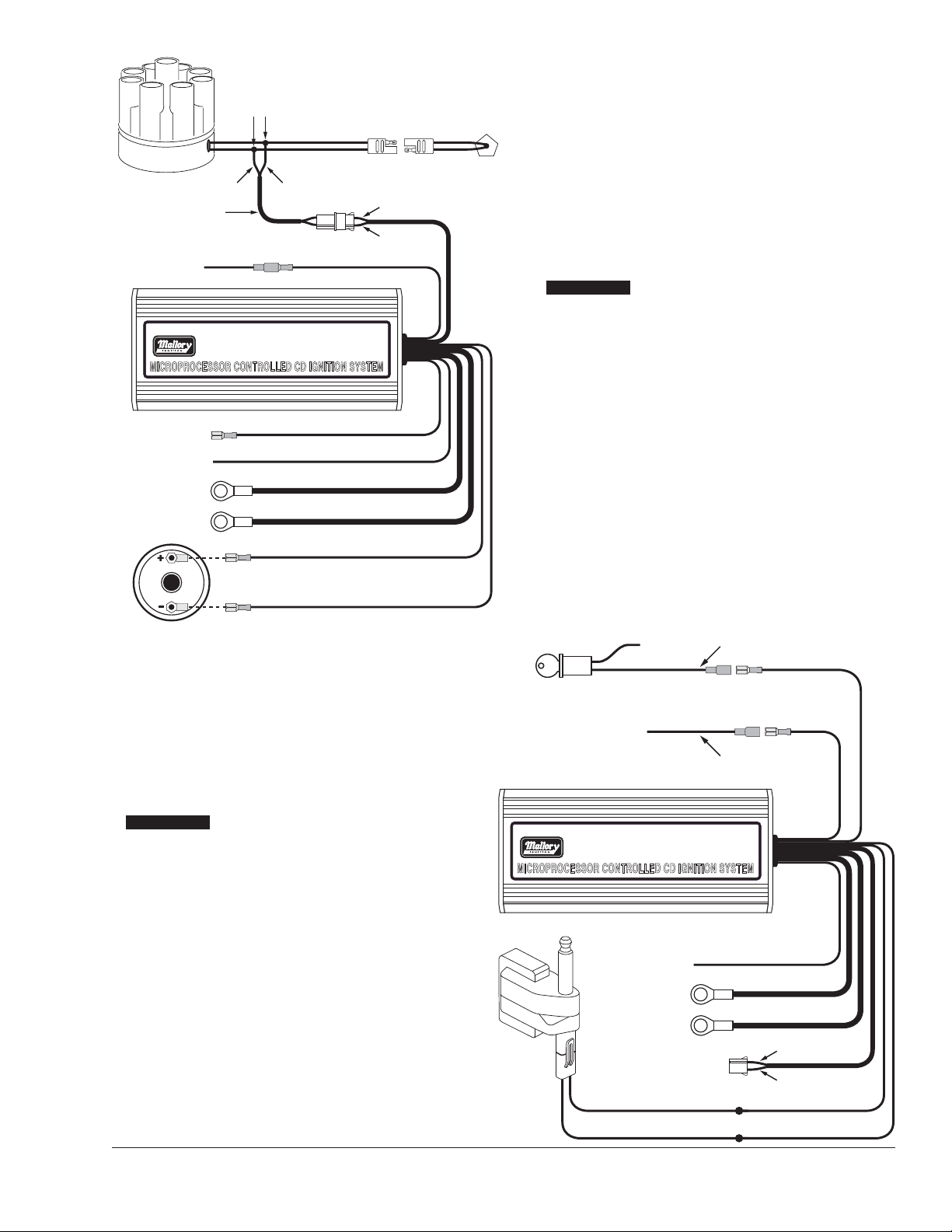
7MALLORY TECHNICAL SUPPORT (216) 688-8300 tech@mrgasket.com
Installing the HYFIRE®6A with a
Mallory 81-84 Series Distributor
(2-Wire Magnetic Pickup)
Installing the HYFIRE®6A with a Dual
Connector Coil HEI System
FIGURE 11
FIGURE 12
HHYYFFIIRREE 66AA
HHYYFFIIRREE 66AA
®
PURPLE
GREEN
RED (LARGE 14 GA)
BLACK (LARGE 14 GA)
YELLOW
RED (SMALL 18 GA)
TO BATTERY POS (
TO BATTERY NEG (
TO TACHOMETER
PART OF MALLORY HEI
+
)
KIT P/N 29008 (NOT
INCLUDED)
-
)
RED
RED
WHITE WHITE
BLACK WHITE
WHITE (NOT USED)
PINKORANGE
PINK
PINK
CONNECT FACTORY TACH HERE
TO IGNITION SWITCH
FROM DISTRIBUTOR
PINK (NOT USED)
WHITE
R
®
PART No. 6852
SPLICE WIRES AT THESE LOCATIONS
Page 8
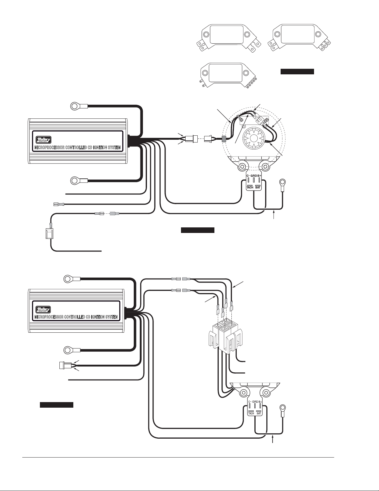
MALLORY IGNITION www.malloryperformance.com8
There are three different large cap HEI distributors. To identify which
of the following diagrams fit your specific application, remove the
distributor cap and rotor and locate the ignition module at the base
of the distributor. Count the number of terminals on both ends of the
module and follow the corresponding diagram. GM used 4, 5, and
7-pin modules in these distributors.
NOTE: Some 5-pin modules may experience a hesitation or stall on
deceleration. If this occurs, contact the Mallory Technical Service
Department for the required bolt-in diode to correct the problem.
4-Pin Module 5-Pin Module
Installing the HYFIRE®6A with an HEI
4-Pin Module (Magnetic Pickup Trigger)
Installing the HYFIRE®6A
with an HEI 5-Pin
or 7-Pin Module
(Amplifier Trigger)
7-Pin Module
FIGURE 13
FIGURE 14
FIGURE 15
HHYYFFIIRREE 66AA
HHYYFFIIRREE 66AA
TO BATTERY POS (+)
PART No. 6852
®
TO BATTERY NEG (
TO TACHOMETER
NOT USED
TO BATTERY POS (+)
-
)
WHITE JUMPER
KEY CONNECTOR
RED (LARGE 14 GA)
R
BLACK (LARGE 14 GA)
YELLOW
WHITE
RED (SMALL 18 GA)
HEAVY RED OR PINK WIRE FROM CAR
WIRING HARNESS
RED (LARGE 14 GA)
RED (SMALL 18 GA)
WHITE
PART OF MALLORY HEI KIT
P/N 29008 (NOT INCLUDED)
PURPLE
GREEN
GREEN
BLACK (SMALL 18 GA TO Cñ)
ORANGE (TO B+)
PURPLE
PART OF MALLORY HEI KIT
P/N 29008 (NOT INCLUDED)
RED JUMPER
WHITE JUMPER
PART OF MALLORY
HEI KIT P/N 29008
(NOT INCLUDED)
WHITE
GREEN
TO ENGINE
GROUND
PART No. 6852
®
TO BATTERY NEG (–)
NOT USED
TO TACHOMETER
R
BLACK (LARGE 14 GA)
GREEN
PURPLE
YELLOW
PART OF MALLORY HEI KIT
P/N 29008 (NOT INCLUDED)
BLACK (SMALL 18 GA TO Cñ)
ORANGE (TO B+)
HEAVY PINK OR RED FROM
VEHICLE WIRE HARNESS
TO TACH
TO ENGINE
GROUND
PART OF MALLORY
HEI KIT P/N 29008
(NOT INCLUDED)
Page 9
BLACK (LARGE 14 GA)
TO BATTERY NEG (
-
)
RED (LARGE 14 GA)
TO BATTERY POS (+)
PART No. 6852
R
MAGNETIC PICKUP
NOT USED
WHITE
RED (SMALL 18 GA)
RED
JUMPER
WHITE JUMPER
NOT USED (TAPE END)
ORANGEBLACK
(SMALL
18 GA)
FROM DISTRIBUTOR
PINK
BROWN
HEAVY PINK, ORANGE, OR RED WIRE
GREEN
PURPLE
PART OF MALLORY
HEI KIT P/N 29008
(NOT INCLUDED)
PART No. 6852
R
BLACK (SMALL 18GA)
ORANGE
YELLOW
GREEN
COIL
TO TACHOMETER
BLACK (LARGE 14GA)
RED (LARGE 14GA)
PURPLE
TO BATTERY NEG (
-
)
TO BATTERY POS (
+
)
MAGNETIC PICK-UP
(NOT USED)
GREEN
RED
WHITE
(SMALL 18 GA)
RED (SMALL 18 GA)
9MALLORY TECHNICAL SUPPORT (216) 688-8300 tech@mrgasket.com
Installing the HYFIRE®6A with an
External 4-Terminal Coil (Single
Connector)
Installing the HYFIRE®6A with
a Ford Duraspark using the
White Wire Trigger
FIGURE 16
FIGURE 17
HHYYFFIIRREE 66AA
HHYYFFIIRREE 66AA
®
®
Page 10
®
PART No. 6852
R
BLACK (SMALL 18GA)
ORANGE
YELLOW
TO TACHOMETER
BLACK (LARGE 14GA)
INSULATE UNUSED
ENDS OF JUMPERS
TO BATTERY NEG (
-
)
RED (LARGE 14GA)
TO BATTERY POS (
+
)
WHITE
RED (SMALL 18GA)
GREEN
PURPLE
MAGNETIC PICK-UP
(NOT USED)
RED
WHITE
PART OF MALLORY
HEI KIT P/N 29008
(NOT INCLUDED)
PART No. 6852
R
YELLOW
TO TACHOMETER
BLACK (LARGE 14 GA)
TO BATTERY NEG (
-
)
RED (LARGE 14 GA)
TO BATTERY POS (
+
)
GREEN
PURPLE
MAGNETIC PICK-UP
(NOT USED)
WHITE
RED
BLACK
ORANGE
GREEN
RED
BLACK
YELLOW
ADAPTER/HARNESS P/N 29062
(NOT INCLUDED)
YELLOW BLACK
FACTORY HARNESS PLUG
(ORIGINALLY CONNECTED
TO THE COIL)
RED GREEN
MALLORY IGNITION www.malloryperformance.com10
Installing the HYFIRE®6A
with a Ford TFI
(Without Harness)
Installing the HYFIRE®6A
with a Ford TFI
(With Harness)
FIGURE 18
FIGURE 19
HHYYFFIIRREE 66AA
HHYYFFIIRREE 66AA
®
Page 11
PART No. 6852
R
BLACK (SMALL 18 GA)
ORANGE
BLACK/GRAY OR GRAY
YELLOW
TO TACHOMETER
RED (LARGE 14 GA)
TO BATTERY POS (
+
)
BLACK (LARGE 14 GA)
TO BATTERY NEG (
-
)
WHITE
ORIGINAL COIL (+)
GREEN
PURPLE
GREEN/ORANGE
RED (SMALL 18 GA)GREEN/ORANGE
IGNITION
TO 12 VOLTS
MAGNETIC PICKUP
NOT USED
BLACK/GRAY
FROM POINTS OR
ELECTRONIC IGNITION
ORIGINAL COIL (-)
®
PART No. 6852
R
BLACK (SMALL 18 GA)
ORANGE
COIL
WHITE
NOT USED
YELLOW
TO TACHOMETER
RED (LARGE 14 GA)
TO BATTERY POS (
+
)
BLACK (LARGE 14 GA)
TO BATTERY NEG (
-
)
RED (SMALL 18 GA)
FROM
ORIGINAL COIL
BLACK
ORANGE
CHRYSLER
MODULE
VIOLET GREEN
GREEN
PURPLE
6 FT EXTENSION CABLE
CUT ONE END AND
SPLICE AS SHOWN
SPLICE
11MALLORY TECHNICAL SUPPORT (216) 688-8300 tech@mrgasket.com
Installing the HYFIRE®6A with a
Chrysler Electronic Ignition using
a Magnetic Pickup Trigger
Installing the HYFIRE®6A with a Late
Model Dodge (with 2-Pin Connector)
FIGURE 20
FIGURE 21
HHYYFFIIRREE 66AA
HHYYFFIIRREE 66AA
®
Page 12

®
PART No. 6852
R
YELLOW
TO TACHOMETER
RED (LARGE 14 GA)
TO BATTERY POS (
+
)
BLACK (LARGE 14 GA)
TO BATTERY NEG (
-
)
GREEN
PURPLE
RED (SMALL 18 GA)
MAGNETIC PICKUP
NOT USED
ORIGINAL COIL (+) WIRE
SPLICE HERE
WHITE
(
-
) BLACK (SMALL 18 GA)
AMPLIFIER
ORIGINAL COIL (
-
)
TERMINAL FROM
AMPLIFIER
TO IGNITION
SWITCH
(+) ORANGE
SPLICE HERE
MALLORY IGNITION www.malloryperformance.com12
Installing the HYFIRE®6A with
a Typical Import Application
FORM 1522TL
Made in U.S.A.
Printed in U.S.A.
MALLORY IS A DIVISION OF PRESTOLITE PERFORMANCE
(216) 688-8300
RPM LIMITER SETTINGS
Note the sticker attached to the end plate of the HYFIRE®6-AL.
This sticker shows settings for number of cylinders and RPM
limits. In case the sticker becomes damaged or otherwise
unreadable, the settings are shown at right.
Setting Switch #4
This switch must remain in the down position for normal
operation. CAUTION: Using the Mallory HYFIRE®6-AL (6AL) with
switch #4 in the up position could cause ignition damage.
Rotary Switch Switch #1 Switch #1
Position DOWN UP
0 4,500 8,500
1 4,750 8,750
2 5,000 9,000
3 5,250 9,250
4 5,500 9,500
5 5,750 9,750
6 6,000 10,000
7 6,250 10,250
8 6,500 10,500
9 6,750 10,750
A 7,000 11,000
B 7,250 11,250
C 7,500 11,500
D 7,750 11,750
E 8,000 12,000
F 8,250 NO LIMIT
Number of
Cylinders Switch #2 Switch #3
4 UP Down
6 Down UP
8 Down Down
FIGURE 22
FIGURE 23
HHYYFFIIRREE 66AA
Page 13

13MALLORY TECHNICAL SUPPORT (216) 688-8300 tech@mrgasket.com
CONTROL DE ARRANQUE ELECTRÓNICO
HYFIRE®SERIES 6-A y 6-AL
NÚMEROS DE PIEZAS 6852M (6-A) y 6853M (6-AL)
INSTRUCCIONES DE INSTALACIÓN
FORM 1522TL
INFORMACIÓN GENERAL
Las características del HYFIRE®6-A y HYFIRE®6-AL son idénticas,
excepto:
HYFIRE®6-AL incluye un circuito limitador de RPM de
una fase.
Se pueden establecer varios límites de RPM mediante
interruptores que se acceden mediante la sección rectangular
recortada en el soporte terminal. Vea la página 12 de estas
instrucciones para obtener información adicional sobre las
características de limitación de revoluciones del HYFIRE®6-AL.
Batería
El control de arranque serie HYFIRE®6A funciona en cualquier
sistema eléctrico de 12 voltios con tierra negativa que tenga
distribuidor. También funciona con baterías de 16 voltios y puede
soportar picos momentáneos de 24 voltios en caso de arranques
con conexión en puente provisional. Este sistema proporciona el
voltaje completo con suministro de 10 a 18 voltios y funciona con
un voltaje de suministro de hasta 8 voltios.
Si su aplicación no utiliza alternador, debe dejar por lo menos 15
amperios/hora por cada media hora de funcionamiento. Si el motor
gira con la misma batería que utilizan otros accesorios, tales como
una bomba eléctrica de combustible o agua, aumente la capacidad
de amperios/hora.
Bobinas
Para obtener el rendimiento óptimo con el control de arranque
HYFIRE®6A, se recomienda el uso de la bobina Mallory
PROMASTER®, número de pieza 29440 o 30440. También se puede
utilizar la bobina Mallory PROMASTER®, número de pieza 29625,
como también la mayoría de las bobinas originales o de repuesto
diseñadas para reemplazar las originales.
NOTA: No utilice la bobina Mallory PROMASTER®, número de
pieza 28880.
Tacómetros
El cable amarillo del control de arranque HYFIRE®6A proporciona
una señal de disparador para los tacómetros, luces de cambios y
otros dispositivos adicionales activados por las RMP. Este cable
genera una señal de onda cuadrada de 12 voltios con un ciclo de
trabajo del 20%.
Algunos vehículos con tacómetros instalados en fábrica pueden
requerir un adaptador de tacómetro para utilizar el control de
arranque HYFIRE®6A. Si su vehículo GM utiliza un filtro en línea,
éste puede hacer que el tacómetro baje a cero al acelerar. Si esto
sucede, derive el filtro. Para obtener más información sobre el uso
de tacómetros, consulte la página 4.
Bujías
El uso de las bujías y extensión térmica apropiadas es importante
para obtener el rendimiento óptimo. Debido a la cantidad de
variables que se deben considerar, sugerimos que comience por las
bujías recomendadas por el fabricante de su motor. Luego puede
experimentar con leves modificaciones en la calibración de las
bujías y la extensión térmica para obtener el mejor rendimiento del
motor. Utilice el gráfico a la derecha como punto inicial. También se
recomienda el uso de bujías sin resistor.
Vehículos extranjeros
Debido a los sistemas de inyección de combustible modernos,
algunos vehículos extranjeros pueden requerir un adaptador de
tacómetro/inyección de combustible para utilizar el control de
arranque HYFIRE
®
6A.
NOTA: No instale el control de arranque HYFIRE®6A en ningún
vehículo que originalmente viene equipado con un
control de arranque de CD.
Bujías y cables
Los cables de alta calidad y bobinados en espiral, y el cableado
apropiado son fundamentales para el funcionamiento del control de
arranque HYFIRE®6A. Este tipo de cable proporciona una buena
ruta para la chispa y al mismo tiempo minimiza la interferencia
electromagnética (EMI, por sus siglas en ingles).
NOTA: No utilice cables para bujías con núcleos sólidos con el
control de arranque HYFIRE®6A.
Colocación del cableado
Los cables se deben colocar lejos de los bordes agudos, objetos en
movimiento y fuentes de calor. Se deben separar los cables que
están al lado de otros cables en el orden de encendido del motor.
Por ejemplo, en los motores Chevy V8 con orden de encendido
1-8-4-3-6-5-7-2, los cilindros 5 y 7 están ubicados uno al lado del
otro en el motor y en el orden de encendido. El voltaje del cable 5
podría saltar al cable 7. Esto podría ocasionar detonaciones y
averías en el motor. Para obtener protección adicional contra la
interferencia, Mallory cuenta con el forro aislado PRO SHIELD. Pro
Shield es un forro protector de tejido de vidrio y revestido de silicón
que se desliza sobre los cables de las bujías. También ayuda a
reducir los daños producidos por el calor y los objetos agudos.
1 Control de arranque HYFIRE
®
6A
4 Tornillos para hoja metálica Nº 10
2 Amarres para cables
2 Terminales de anillo, aislados
1 Diodo de 1 amperio/100 voltios
2 Terminales de lengüeta de 6,35 mm (1/4 de pulg.)
5 Disyuntores macho de 6,35 mm (1/4 de pulg.)
5 Disyuntores hembra de 6,35 mm (1/4 de pulg.)
1 Ojal de goma
2 Abrazaderas para cables
1 Extensión del circuito de absorción magnética
PIEZAS INCLUIDAS:
Page 14

MALLORY IGNITION www.malloryperformance.com14
Cuando consiga una ubicación apropiada para montar la unidad,
asegúrese de que los cables del arranque alcancen las conexiones.
Sujete el arranque en su sitio y marque la posición de los agujeros
de montaje. Utilice una broca de 3,175 mm (1/8 de pulg.) para
taladrar los agujeros. Utilice los tornillos autorroscantes
suministrados para montar la caja.
CABLEADO
Largo de los cables
Todos los cables del control de arranque HYFIRE®6A se pueden
acortar con tal que se utilicen o suelden conectores de calidad en
el sitio. Para alargar los cables, utilice cable de un calibre superior
(calibre 12 para los cables de energía, calibre 16 para los demás
cables). Utilice los conectores apropiados para terminar todos los
cables. Todas las conexiones se deben soldar y sellar.
Conexiones a tierra
La conexión indebida a tierra puede ocasionar muchos problemas
frustrantes. Cuando se deba conectar un cable específico a tierra,
conéctelo al chasis. Siempre conecte una correa de conexión a
tierra entre el motor y el chasis. Conecte todos los cables de
conexión a tierra a una superficie metálica que esté limpia y sin
pintura.
Resistor de balasto
Si su vehículo cuenta con un resistor de balasto en línea con el
cableado de la bobina, no será necesario derivarlo. Esto se debe a
que el control de arranque HYFIRE®6A recibe la energía principal
directamente de la batería.
INFORMACIÓN MISCELÁNEA
Sellado
No intente sellar el control de arranque HYFIRE®6A. Todos los
circuitos del HYFIRE®6A reciben un revestimiento de conformación
de sellador que protege los componentes electrónicos de la
humedad. Al sellar el HYFIRE®6A no permitirá que la humedad que
penetra en los ojales salga, lo que puede resultar en corrosión.
Soldadura
Para evitar averiar el control de arranque HYFIRE®6A, al soldar
alguna pieza del vehículo desconecte los cables de energía positivo
(rojo) y negativo (negro) del control de arranque HYFIRE®6A.
También es aconsejable desconectar el cable de conexión a tierra
del tacómetro.
Tapa del distribuidor y rotor
Se recomienda la instalación de una nueva tapa del distribuidor y
rotor al instalar el control de arranque HYFIRE®6A. Asegúrese de
que la tapa esté limpia por dentro y por fuera, especialmente las
terminales y la punta del rotor. Es posible que en los vehículos con
tapas pequeñas, el aire dentro de éstas se cargue con electricidad
y ocasione interferencia que puede resultar en fallas del encendido.
Puede evitar que esto suceda taladre dos agujeros de ventilación
en la tapa. Taladre los agujeros entre las terminales a la altura del
rotor, en el lado opuesto de la toma. Si se requiere, ponga un trozo
pequeño de malla sobre los agujeros para que sirva de filtro.
LED de diagnósticos del Hyfire®6A
En el panel terminal del control de arranque Hyfire®6A hay un
agujero pequeño. Detrás del agujero está un indicador LED rojo.
Éste cumple dos funciones: cuando enciende por primera vez el
interruptor del arranque el LED parpadeará rápidamente 3 veces.
Esto indica que el sistema de arranque tiene energía y que el
microprocesador funciona debidamente. Además, el LED
parpadeará cuando reciba la señal apropiada de disparador del
vehículo. Si luego del encendido normal el LED no parpadea al
girar el motor, deberá verificar el circuito
disparador para ver si tiene problemas. Si el
LED parpadea cuando gira el motor, pero no
hay chispa, el problema está en otro sitio.
Selección de cilindro para el
Hyfire®6A
El control de arranque HYFIRE®6A
viene configurado de la fábrica para el
funcionamiento con 8 cilindros. Si desea
utilizar este arranque con un motor de 4 ó 6
cilindros, primero debe quitar los cuatro
tornillos que sujetan la placa terminal que tiene
el agujero LED. Cuando quite la placa terminal, verá
el extremo de la tarjeta de circuito. Busque el interruptor
de dos secciones. Para seleccionar el modo de 4 cilindros,
ponga el interruptor marcado "1" en la posición "ON". Para
seleccionar el modo de 6 cilindros, ponga el interruptor marcado
"2" en la posición "ON". Si ambos interruptores están en la
posición "OFF" o en "ON", el arranque funcionará en el modo de 8
cilindros. Consulte la figura 1.
MONTAJE
El control de arranque HYFIRE®6A se puede montar en cualquier
posición. Si lo monta en el compartimiento del motor, manténgalo
alejado de los objetos en movimiento y las fuentes de calor. No
monte la unidad en un sitio cerrado, como en la guantera.
LABELS FOR
"CYLINDER SELECT"
ON CIRCUIT BOARD
DIAGNOSTIC
LED
FIGURA 1
LED DE
DIAGNÓSTICOS
ETIQUETAS PARA
"SELECCIÓN
DE CILINDRO" EN
LA TARJETA DE
CIRCUITOS
Page 15

15MALLORY TECHNICAL SUPPORT (216) 688-8300 tech@mrgasket.com
FROM HYFIRE® VIA
WHITE
BLACK
USING THE MAGNETIC
PICKUP WIRE TO TRIGGER
THE HYFIRE
®
VIA
USING THE WHITE
WIRE TO TRIGGER
THE HYFIRE
®
VIA
CONNECTS TO
PURPLE
BLACK
MAGNETIC PICKUP
PURPLE
GREEN
LISTA DE VERIFICACIÓN DE PREARRANQUE
• Los únicos cables conectados a los terminales de la bobina
deben ser el naranja al terminal positivo (+) y el negro conectado
al terminal negativo (–).
• El cable rojo delgado se conecta a una fuente conmutada de
12 voltios, tal como la llave del encendido.
• Los cables de energía se conectan directamente a los terminales
positivo y negativo de la batería.
• Si no utiliza el alternador, la batería se debe conectar y cargar
totalmente.
• El motor tiene por lo menos una correa de conexión a tierra
conectada al chasis.
DISPOSITIVO ANTIRROBOS
El control de arranque HYFIRE®6A proporciona una manera
fácil de instalar un interruptor de apagado que sirve de dispositivo
antirrobos. Consulte la figura 2.
Disparador de cable blanco
Al utilizar el cable blanco para disparar el control de arranque
HYFIRE®6A, instale un interruptor entre el cable blanco del circuito
de absorción magnética y la tierra. Cuando el cable blanco se
conecta a tierra, el motor del vehículo girará, mas no arrancará.
Disparador de circuito de absorción magnética
Al utilizar el circuito de absorción magnética para disparar el
control de arranque HYFIRE®6A, instale un interruptor entre el cable
violeta y el otro lado a tierra. Cuando el cable violeta se conecta a
tierra, el motor del vehículo girará, mas no arrancará.
FIGURA 2
FUNCIONES DEL CABLEADO
Cables de energía
Los dos cables de calibre grueso (calibre 14) que trasmiten el
voltaje de la batería al arranque:
Rojo grueso Se conecta directamente al terminal positivo (+)
de la batería o a un empalme positivo de la
batería. También se puede conectar al lado
positivo del solenoide del arranque.
NOTA: Nunca conecte este cable al alternador.
Negro grueso Se conecta a la conexión a tierra del chasis.
Cables del disparador y bobina
Rojo delgado Se conecta a una fuente conmutada de 12
voltios, tal como la llave del encendido.
Naranja Se conecta al terminal positivo (+) de la bobina.
NOTA: Este es el único cable que hace
contacto eléctrico con el terminal positivo (+)
de la bobina.
Negro delgado Se conecta al terminal negativo (–) de la bobina.
NOTA: Este es el único cable que hace
contacto eléctrico con el terminal negativo (–)
de la bobina.
Cables del Cualquiera de los dos circuitos disparará el
control de arranque HYFIRE®6A: un circuito de
puntos (cable blanco) o un circuito de absorción
magnética (cables violeta o verdes).
NOTA: Nunca se utilizarán los dos circuitos al
mismo tiempo.
Blanco Se conecta a los puntos, a la salida del
amplificador de arranque electrónico o al cable
verde del accesorio de tiempos Mallory. Cuando
se utiliza este cable, no se utiliza el conector de
absorción magnética.
Violeta/verde Estos cables se colocan juntos en un arnés para
formar el conector de absorción magnética.
El conector se enchufa directamente en el
distribuidor Mallory o disparador de giro del
motor. También se puede enchufar en los
conectores de absorción magnética instalados en
fábrica u otros conectores de repuesto. El cable
violeta es positivo (+) y el verde es negativo (–).
Cuando se utilizan estos cables, no se utiliza el
cable blanco. Consulte el gráfico que muestra la
polaridad de otros conectores de absorción
magnética comunes.
Amarillo Se conecta al tacómetro.
COLOCACIÓN DEL CABLEADO
Coloque todos los cables lejos de las fuentes de calor, bordes
agudos y objetos en movimiento. Separe los cables del disparador
de los otros cables, incluso los de las bujías. De ser posible,
colóquelos a lo largo de un plano conectado a tierra, como el
bloque del motor o la mampara cortafuegos, que crea un blindaje
eléctrico. Los cables del circuito de absorción magnética deben
colocarse por separado y se deben enroscar juntos para ayudar
a reducir la interferencia excedente.
ADVERTENCIA: El control de arranque HYFIRE®6A es un
arranque de descarga capacitiva. El voltaje alto se encuentra
en los terminales principales de la bobina.
No toque estos terminales ni conecte
equipos de prueba en éstos.
Cables del
disparador
COLORES COMUNES DE LOS CABLES
DEL CIRCUITO DE ABSORCIÓN MAGNÉTICA
Distribuidor Mag + Mag –
Disparador de giro del motor Mallory Morado Verde
Distribuidor de carrera de palanquilla Mallory,
números de serie 81 y 84 Naranja Morado
Mallory Comp
®
9000 número de serie 96-99 Naranja Morado
Arnés Mallory número de pieza 29040 Rojo Negro
MSD Naranja/negro Violeta/negro
Disparador de giro del motor MSD Naranja/negro Violeta/negro
Ford Naranja Morado
Accel serie 46/48000 Naranja/negro Violeta/negro
Accel serie 51/61000 Rojo Negro
Chrysler Naranja/blanco Negro
USO DEL CABLE DEL
CIRCUITO DE
ABSORCIÓN MAGNÉTICA
PARA DISPARAR EL
HYFIRE
®
6A
USO DEL CABLE BLANCO
PARA DISPARAR EL
HYFIRE®6A
DESDE EL HYFIRE®6A
BLANCO
NEGRO
NEGRO
MORADO
CIRCUITO DE
ABSORCIÓN MAGNÉTICA
SE CONECTA AL
MORADO
VERDE
Page 16

MALLORY IGNITION www.malloryperformance.com16
FOR EARLY GM VEHICLES
ATTACH DIODE TO
#4 TERMINAL
FOR FORD VEHICLES
ATTACH DIODE TO
#1 TERMINAL
1A-100V DIODE
TO CHARGING LIGHT
SPLICE HERE
DELCOTRON
ALTERNATOR
1A-100V DIODE
TO CHARGING LIGHT
SPLICE HERE
SMALL RED
FROM HYFIRE
®
VIA
12 VOLT
IGNITION SWITCH
CHRYSLER DUAL
BALLAST RESISTOR
WHITE WIRE FROM
HYFIRE® VIA
FROM POINTS OR
AMPLIFIER
LISTA DE COMPATIBILIDAD CON TACÓMETRO
Tacómetro Disparador De Conector Del
De Repuesto Cable Blanco Disparador Magnético
Autogage 29074 29078
Autometer — —
Ford Motorsport — —
Moroso — —
Stewart 29074 29078
S.W. & Bi Torx — —
Sun 29074 29078
VDO 8910 29078
AMC (Jeep) 29074 29078
Chrysler 29074 29078
Ford (Before 1976) 29074 29078
Ford (After 1976) 29074 29078
GM Filtro de derivación Filtro de derivación
en línea en línea
Imports 29074 29078
RESOLUCIÓN DE PROBLEMAS
Esta sección ofrece varias pruebas y verificaciones que puede realizar
para asegurar la instalación y funcionamiento apropiados del control de
arranque HYFIRE
®
6A. Si tiene problemas con el HYFIRE®6A, primero
verifique que la instalación esté bien hecha o si hay conexiones indebidas. Puede solucionar muchos problemas verifi-cando estos elementos. Si tiene preguntas sobre el control de arranque HYFIRE
®
6A, póngase en contacto con el departamento de servicio técnico de Mallory
(Mallory Technical Service Department), llamando al 775-882-6600, de
lunes a viernes, de 8:00 am a 5:00 pm (huso horario del Pacífico en
EE.UU.).
Adaptadores de tacómetro/combustible
Si el tacómetro no funciona debidamente, probablemente requiera un
adaptador de tacómetro Mallory. Consulte la lista de compatibilidad de
los tacómetros que está a la derecha para obtener los tacómetros
comunes y los adaptadores de tacómetro compatibles.
No funcionan los vehículos extranjeros
Algunos vehículos extranjeros con sistemas de inyección de
combustible pueden requerir un adaptador de tacómetro/inyección
de combustible para utilizar el control de arranque HYFIRE
®
6A.
Frecuentemente se utiliza la misma fuente de disparador para
hacer funcionar el arranque, tacómetro y sistema de inyección de combustible. Esto da como resultado una señal de voltaje demasiado baja
para disparar el sistema de inyección de combustible. El
adaptador de tacómetro/inyección de combustible generalmente soluciona este problema.
No funciona el tacómetro
Si el tacómetro no funciona con el HYFIRE
®
6A instalado, probablemente requiere un adaptador de tacómetro Mallory. Antes de comprar
el adaptador de tacómetro, intente conectar el cable del disparador de
tacómetro al cable amarillo del control de arranque HYFIRE
®
6A. Esta
salida produce una onda cuadrada de 12 voltios. Si el tacómetro
todavía no funciona debidamente, requerirá un adaptador de
tacómetro. Hay dos adaptadores de tacómetro distintos disponibles:
Número de pieza 29078 Si utiliza el conector de absorción magnética
(cables verde y violeta) para disparar el HYFIRE
®
6A, debe uti-
lizar este adaptador.
Número de pieza 29074 Si el tacómetro se dispara del terminal
negativo de la bobina (disparado por voltaje) y utiliza el cable
blanco para disparar el HYFIRE
®
6A, debe utilizar este
adaptador.
Resistor de balasto
Si tiene un tacómetro disparado por corriente (originalmente
conectado al positivo (+) de la bobina) y utiliza el cable blanco del
HYFIRE
®
6A para disparar, puede comprar el resistor de doble balasto
Chrysler (aplicaciones de 1973 a 1976). Cabléelo como se muestra en
la figura 3.
Motor que continúa encendido
Si el motor continúa encendido con el arranque apagado, experi-menta
una falla que se denomina encendido continuo. Generalmente los
vehículos más viejos con regulador de voltaje externo son más susceptibles a esta condición. Debido a que el control de arranque HYFIRE
®
6A
recibe energía directamente de la batería, no se requiere mucha corriente para mantener la unidad energizada. Si el motor continúa encendido, se debe a una pequeña cantidad de voltaje que pasa por el indicador de la luz de carga que alimenta el cable rojo delgado (aún si la
llave está apagada).
GM 1973 a 1983 con alternadores Delcotron
Los alternadores GM Delcotron utilizan un regulador de voltaje
interno. Instale el diodo en línea con el cable más delgado que sale del
alternador (vea la figura 5). Por lo general el cable es marrón.
La mayoría de las otras aplicaciones: Para eliminar el problema del
motor que continúa encendido, coloque un resistor en línea con el
cable rojo delgado del HYFIRE
®
6A para que el voltaje no se fugue al
arranque HYFIRE
®
6A.
FIGURA 3
Modelos Ford y GM antiguos: Para solucionar el problema del motor
que continúa encendido, se suministra un diodo con el control de
arranque HYFIRE
®
6A. Al instalar este diodo en línea en el cable que va
al indicador de carga, se bloquea el voltaje para que no entre al control
de arranque HYFIRE
®
6A. La figura 4 muestra la instalación debida del
diodo para vehículos Ford y GM antiguos.
NOTA: Los diodos se utilizan para permitir que el voltaje
fluya en una sola dirección. Asegúrese de que el diodo está instalado hacia la dirección apropiada, como se muestra en la figura 4.
Ford: Instale el diodo en línea con el cable que va al terminal 1.
GM: Instale el diodo en línea con el cable que va al terminal 4.
FIGURA 4
FIGURA 5
INTERRUPTOR
DE ARRANQUE
DE 12 VOLTIOS
CABLE ROJO DELGADO
DESDE EL HYFIRE®6A
DESDE LOS PUNTOS
O AMPLIFICADOR
CABLE BLANCO
DESDE EL
HYFIRE®6A
RESISTOR DE DOBLE
BALASTO CHRYSLER
PARA LOS
VEHÍCULOS FORD,
CONECTE EL DIODO
AL TERMINAL
NÚMERO 1
PARA LOS VEHÍCULOS GM
ANTIGUOS, CONECTE EL DIODO
AL TERMINAL NÚMERO 4
HACIA LA LUZ
DE CARGA
EMPALME AQUÍ
EMPALME
AQUÍ
DIODO DE 1A-100V
DIODO DE 1A-100V
ALTERNADOR
DELCOTRON
HACIA LA LUZ
DE CARGA
VOLTAGE
REGULATOR
Page 17

17MALLORY TECHNICAL SUPPORT (216) 688-8300 tech@mrgasket.com
Fallas y problemas intermitentes
La experiencia ha demostrado que si hay fallas del arranque del
motor o titubeo a RPM superiores, por lo general no es una falla de
arranque. Entre las causas más comunes se incluyen las fallas de
la bobina o cables de las bujías, arcos de la tapa o capuchón de la
bujía a tierra o ionización de la chispa dentro de la tapa. Lleve a
cabo las siguientes verificaciones:
• Revise los cables de las bujías en la tapa y en las bujías para
asegurarse que la conexión sea segura. Haga una inspección
ocular para ver si hay cortes, abrasiones o quemaduras.
• Inspeccione las conexiones del cable principal de la bobina.
Debido a que el control de arranque HYFIRE®6A recibe una
fuente directa de 12 voltios de la batería, no habrá voltaje en el
terminal positivo (+) de la bobina, aún con la llave encendida.
Durante el giro del motor o cuando éste esté encendido, habrá
un voltaje muy alto presente, y no se debe conectar ningún
equipo de pruebas.
ADVERTENCIA: No toque los terminales de la bobina cuando el
motor gire o mientras esté encendido.
• Asegúrese de que la batería esté totalmente cargada y que las
conexiones estén limpias y seguras. Si no utiliza un alternador,
esta verificación es obligatoria. Si el voltaje de la batería cae por
debajo de los 10 voltios durante una carrera, el voltaje de salida
del control de arranque HYFIRE®6A disminuirá.
• ¿El motor funciona de manera eficiente? Inspeccione las bujías y
todo el sistema de combustible.
• Verifique todas las conexiones del cableado para ver si tienen
corrosión o están averiadas. Recuerde utilizar las conexiones
apropiadas seguido por soldadura, luego selle las conexiones
por completo.
Si todo está en regla, utilice el procedimiento a continuación para
probar el arranque para ver si hay chispa. Mallory también cuenta
con un probador de arranque (número de pieza 28357) que
permite verificar todo el sistema de arranque, cuando éste se
encuentra instalado en el vehículo. Esta herramienta también
verifica el funcionamiento de los límites de RPM, interruptores
activados y luces de cambios.
JUMPER WIRE
GREEN
VIOLET
FIGURA 7
TO GROUND
WHITE
WIRE
FIGURA 6
VERIFICACIÓN DE CHISPA
Si se dispara el arranque con el cable blanco:
(Consulte la figura 6)
1. Asegúrese de que el interruptor del arranque se encuentra en la
posición "OFF".
2. Desconecte el cable de la bobina de la tapa del distribuidor y
ponga el terminal aproximadamente a 6,35 mm (1/4 de pulg.)
de la conexión a tierra.
3. Desconecte el cable blanco del control de arranque HYFIRE®6A
de los puntos del distribuidor o del amplificador del arranque.
4. Ponga el arranque en la posición "ON". No haga girar el motor.
5. Golpee ligeramente el cable blanco contra la conexión a tierra
varias veces. Cada vez que retira el cable de la conexión a tierra,
debe saltar una chispa del cable de la bobina a la conexión a
tierra. Si hay chispa, el arranque funciona debidamente. Si no
hay chispa, vaya al paso 6 a continuación.
Si se dispara con el circuito de absorción magnética:
(Consulte la figura 7)
1. Asegúrese de que el interruptor del arranque se encuentra en la
posición "OFF".
2. Desconecte el cable de la bobina de la tapa del distribuidor y
ponga el terminal aproximadamente a 6,35 mm (1/4 de pulg.)
de la conexión a tierra.
3. Desconecte los cables del circuito de absorción magnética del
control de arranque HYFIRE®6A en el distribuidor.
4. Ponga el arranque en la posición "ON". No haga girar el motor.
5. Con un cable de puente corto, junte los cables verde y violeta
del circuito de absorción magnética del control de arranque
HYFIRE®6A para hacer un cortocircuito. Cada vez que elimina
el cortocircuito, debe saltar una chispa del cable de la bobina
la conexión a tierra. Si hay chispa, el arranque funciona
debidamente. Si no hay chispa, vaya al paso 6 a continuación.
6. Si no hay chispa.
A. Inspeccione todo el cableado.
B. Sustituya la bobina y repita la prueba. Si ahora hay chispa,
la bobina tiene fallas.
C. Si todavía no hay chispa, asegúrese de que el cable
rojo delgado del control de arranque HYFIRE
®
6A tenga
suministro de 12 voltios cuando la llave está en la posición
ON. Si no hay suministro de 12 voltios, consiga otra fuente
conmutada de 12 voltios y repita la prueba.
D. Si luego de seguir los procedimientos de prueba e
inspeccionar todo los cables no hay chispa, se debe reparar
el control de arranque HYFIRE®6A. Consulte la sección
Garantía y servicio técnico para obtener información.
Las ilustraciones en las siguientes páginas
muestran la mejor forma de instalar el control de
arranque HYFIRE®6A en distintas aplicaciones.
Si tiene problemas o preguntas al instalar este
dispositivo en su vehículo póngase en contacto
con el departamento de servicio técnico de Mallory
(Mallory Technical Service Department), llamando al
(775) 882-6600, de 8:00 am a 5:00 pm (huso horario
del Pacífico en EE.UU.), o enviando un mensaje de
correo electrónico a tech@mrgasket.com.
CABLE
BLANCO
A TIERRA
CABLE DE PUENTE
6OLETA
VERDE
Page 18

MALLORY IGNITION www.malloryperformance.com18
PART No. 6852
R
BLACK (SMALLER)
ORANGE
YELLOW
COIL
WHITE
GREEN
PURPLE
RED (SMALL 18 GA)
BLACK (LARGE 14 GA)
RED (LARGE 14 GA)
TO BATTERY NEG (
-
)
TO BATTERY POS (
+
)
ORIGINAL COIL (
+
)
IGNITION KEY
NOT USED
TO 12 VOLTS
TO TACHOMETER
FROM MAG PICK-UP DIST
OR CRANK TRIGGER
PART No. 6852
R
IGNITION KEY
TO 12 VOLTS
BLACK (SMALLER)
ORANGE
YELLOW
COIL
WHITEGREEN
BROWN
RED (SMALL 18 GA)
TO TACHOMETER
BLACK (LARGE 14 GA)
TO BATTERY NEG (
-
)
RED (LARGE 14 GA)
TO BATTERY POS (
+
)
RED
TO
ENGINE
CONNECT WIRES AT
THESE POINTS
NOT USED
GREEN
PURPLE
PART No. 6852
R
BLACK (SMALLER)
ORANGE
YELLOW
COIL
WHITE
Original coil wire from points
or electronic ignition amplifier
RED
BLACK (LARGER)
RED (LARGER)
TO BATTERY NEG (
-
)
TO BATTERY POS (
+
)
IGNITION KEY
TO 12 VOLTS
TO TACHOMETER
MAGNETIC PICK-UP
(NOT USED)
Originally connected to coil (+)
FIGURA 8
FIGURA 9
FIGURA 10
Instalación del HYFIRE®6A con un distribuidor de
absorción magnética o disparador de giro del motor
Instalación del HYFIRE®6A con arranque tipo puntos/amplificador
Instalación del HYFIRE®6A con un
distribuidor Mallory UNILITE®o
distribuidor sin cortacircuito magnético
LLAVE DEL ENCENDIDO
LLAVE DEL ENCENDIDO
LLAVE DEL ENCENDIDO
Originalmente conectado al
positivo (+) de la bobina
HACIA 12 VOLTIOS
HACIA 12 VOLTIOS
HACIA 12 VOLTIOS
A NEG (–) DE LA BATERÍA
A NEG (–) DE LA BATERÍA
A POS (+) DE LA BATERÍA
A POS (+) DE LA BATERÍA
ROJO
NARANJA
NARANJA
NEGRO (MÁS GRUESO)
ROJO (MÁS GRUESO)
Cable original de la bobina
desde los puntos o amplificador
de arranque electrónico
CIRCUITO DE ABSORCIÓN
MAGNÉTICA (NO SE UTILIZA)
AL TACÓMETRO
AL TACÓMETRO
A NEG (–) DE LA BATERÍA
A POS (+) DE LA BATERÍA
AL TACÓMETRO
AMARILLO
AMARILLO
NEGRO (MÁS DELGADO)
NEGRO (MÁS DELGADO)
NARANJA
AMARILLO
NEGRO (MÁS DELGADO)
BOBINA
BOBINA
BOBINA
BLANCO
BLANCO
BOBINA ORIGINAL (+)
ROJO (DELGADO
DE CALIBRE 18)
ROJO (DELGADO
DE CALIBRE 18)
NEGRO (GRUESO DE
CALIBRE 14)
ROJO (GRUESO DE CALIBRE 14)
ROJO (GRUESO DE CALIBRE 14)
NEGRO (GRUESO DE CALIBRE 14)
NO SE UTILIZA
NO SE UTILIZA
DESDE EL DISTRIBUIDOR DE
ABSORCIÓN MAGNÉTICA
O DISPARADOR DE GIRO
MORADO
MORADO
VERDE
VERDE
MARRÓN
A TIERRA
DEL MOTOR
CONECTE LOS CABLES
EN ESTOS PUNTOS
VERDE
ROJO
BLANCO
HHYYFFIIRREE 66AA
HHYYFFIIRREE 66AA
HHYYFFIIRREE 66AA
®
®
®
Page 19

19MALLORY TECHNICAL SUPPORT (216) 688-8300 tech@mrgasket.com
PART No. 6852
R
BLACK (SMALLER)
ORANGE
YELLOW
COIL
WHITE
NOT USED
REDORIGINAL COIL (+)
IGNITION KEY TO 12 VOLTS
TO TACHOMETER
RED (LARGE 14 GA)
TO BATTERY POS (
+
)
BLACK (LARGE 14 GA)
TO BATTERY NEG (
-
)
GREEN
PURPLE
FIGURA 11
FIGURA 12
Instalación del HYFIRE®6A con un
distribuidor Mallory serie 81-84 (circuito
de absorción magnética de 2 cables)
Instalación del HYFIRE®6A con un sistema
de bobina HEI (arranque de alta energía)
con doble conector
ROSADO
ROSADO
ROSADO
PARTE DEL JUEGO HEI
MALLORY, NÚM. DE PIEZA
29008 (NO SE INCLUYE)
AL INTERRUPTOR DEL ARRANQUE
DESDE EL DISTRIBUIDOR
CONECTE EL TACÓMETRO DE FÁBRICA AQUÍ
BLANCO (NO SE UTILIZA)
ROSADO (NO SE UTILIZA)
EMPALME LOS CABLES EN ESTOS SITIOS
NARANJA
HACIA 12 VOLTIOS
A NEG (–) DE LA BATERÍA
A POS (+) DE LA BATERÍA
NEGRO (MÁS DELGADO)
LLAVE DEL ENCENDIDO
BOBINA ORIGINAL (+)
ROJO (DELGADO DE CALIBRE 18)
NEGRO (GRUESO DE CALIBRE 14)
ROJO (GRUESO DE CALIBRE 14)
A NEG (–) DE LA
BATERÍA
A POS (+) DE LA
BATERÍA
NEGRO (GRUESO DE CALIBRE 14)
ROJO (GRUESO DE CALIBRE 14)
AL TACÓMETRO
AL TACÓMETRO
BOBINA
NO SE UTILIZA
NEGRO
BLANCO
AMARILLO
MORADO
VERDE
NARANJA
BLANCO
BLANCO
BLANCO
BLANCO
AMARILLO
MORADO
VERDE
ROJO
ROJO
ROJO
HHYYFFIIRREE 66AA
HHYYFFIIRREE 66AA
®
PURPLE
GREEN
RED (LARGE 14 GA)
BLACK (LARGE 14 GA)
YELLOW
RED (SMALL 18 GA)
SPLICE WIRES AT THESE LOCATIONS
R
TO BATTERY POS (
TO BATTERY NEG (
TO TACHOMETER
PART OF MALLORY HEI
+
)
KIT P/N 29008 (NOT
INCLUDED)
-
)
WHITE WHITE
BLACK WHITE
WHITE (NOT USED)
PINKORANGE
RED
RED
PINK
PINK
CONNECT FACTORY TACH HERE
TO IGNITION SWITCH
FROM DISTRIBUTOR
PINK (NOT USED)
WHITE
®
PART No. 6852
Page 20

MALLORY IGNITION www.malloryperformance.com20
4-Pin Module 5-Pin Module
Instalación del HYFIRE®6A con un módulo
HEI de 4 clavijas (disparador del circuito de
absorción magnética)
Instalación del HYFIRE®6A
con un módulo HEI
de 5 ó 7 clavijas
(disparador amplificador)
7-Pin Module
FIGURA 13
FIGURA 14
FIGURA 15
Hay tres distribuidores distintos de tapa grande HEI. Para identificar
cuál de los siguientes diagramas pertenece a su aplicación, quite la
tapa del distribuidor y rotor, y ubique el módulo del arranque en la
base del distribuidor. Cuente la cantidad de terminales en ambos
extremos del módulo y siga el diagrama correspondiente. GM utilizó
módulos de 4, 5 y 7 clavijas en estos distribuidores.
NOTA: Algunos módulos de 5 clavijas pueden experimentar titubeo o el
vehículo se apaga al desacelerar. Si esto sucede, póngase en contacto
con el departamento de servicio técnico de Mallory (Mallory Technical
Service Department) para obtener el diodo que se fija con pernos para
corregir este problema.
PUENTE BLANCO
PUENTE BLANCO
PUENTE ROJO
CONECTOR CLAVE
NEGRO (DELGADO DE CALIBRE 18 A C-)
NARANJA (A B+)
NEGRO (DELGADO DE CALIBRE 18 A C-)
NARANJA (A B+)
ROSADO O ROJO GRUESO DEL ARNÉS
DE CABLES DEL VEHÍCULO
ROSADO O ROJO GRUESO DEL ARNÉS
DE CABLES DEL VEHÍCULO
Módulo de 4 clavijas
Módulo de 5 clavijas
Módulo de 7 clavijas
PARTE DEL JUEGO HEI
MALLORY, NÚM. DE PIEZA
29008 (NO SE INCLUYE)
PARTE DEL JUEGO HEI
MALLORY, NÚM. DE PIEZA
29008 (NO SE INCLUYE)
PARTE DEL JUEGO HEI
MALLORY, NÚM. DE PIEZA
29008 (NO SE INCLUYE)
PARTE DEL JUEGO HEI
MALLORY, NÚM. DE PIEZA
29008 (NO SE INCLUYE)
PARTE DEL JUEGO HEI
MALLORY, NÚM. DE PIEZA
29008 (NO SE INCLUYE)
A NEG (–) DE LA BATERÍA
A POS (+) DE LA BATERÍA
A POS (+) DE LA BATERÍA
AL TACÓMETRO
NO SE UTILIZA
A NEG (–) DE LA BATERÍA
AL TACÓMETRO
AL TACÓMETRO
NO SE UTILIZA
ROJO (DELGADO
DE CALIBRE 18)
ROJO (DELGADO
DE CALIBRE 18)
NEGRO (GRUESO DE CALIBRE 14)
NEGRO (GRUESO DE CALIBRE 14)
ROJO (GRUESO DE CALIBRE 14)
ROJO (GRUESO DE CALIBRE 14)
BLANCO
BLANCO
BLANCO
AMARILLO
MORADO
MORADO
VERDE
AMARILLO
MORADO
VERDE
VERDE
VERDE
A TIERRA
DEL MOTOR
A TIERRA
DEL MOTOR
HHYYFFIIRREE 66AA
HHYYFFIIRREE 66AA
TO BATTERY POS (+)
RED (LARGE 14 GA)
PART OF MALLORY HEI KIT
P/N 29008 (NOT INCLUDED)
PURPLE
WHITE
PART No. 6852
®
TO BATTERY NEG (
TO TACHOMETER
NOT USED
KEY CONNECTOR
TO BATTERY POS (+)
PART No. 6852
®
R
BLACK (LARGE 14 GA)
-
)
WHITE JUMPER
RED (LARGE 14 GA)
R
PURPLE
YELLOW
WHITE
RED (SMALL 18 GA)
HEAVY RED OR PINK WIRE FROM CAR
WIRING HARNESS
RED (SMALL 18 GA)
WHITE
PART OF MALLORY HEI KIT
P/N 29008 (NOT INCLUDED)
GREEN
BLACK (SMALL 18 GA TO Cñ)
ORANGE (TO B+)
GREEN
TO ENGINE
GROUND
PART OF MALLORY HEI KIT
P/N 29008 (NOT INCLUDED)
RED JUMPER
WHITE JUMPER
PART OF MALLORY
HEI KIT P/N 29008
(NOT INCLUDED)
GREEN
TO BATTERY NEG (–)
GREEN
NOT USED
TO TACHOMETER
PURPLE
BLACK (LARGE 14 GA)
YELLOW
BLACK (SMALL 18 GA TO Cñ)
ORANGE (TO B+)
HEAVY PINK OR RED FROM
VEHICLE WIRE HARNESS
TO TACH
TO ENGINE
GROUND
PART OF MALLORY
HEI KIT P/N 29008
(NOT INCLUDED)
Page 21

21MALLORY TECHNICAL SUPPORT (216) 688-8300 tech@mrgasket.com
BLACK (LARGE 14 GA)
TO BATTERY NEG (
-
)
RED (LARGE 14 GA)
TO BATTERY POS (+)
PART No. 6852
R
MAGNETIC PICKUP
NOT USED
WHITE
RED (SMALL 18 GA)
RED
JUMPER
WHITE JUMPER
NOT USED (TAPE END)
ORANGEBLACK
(SMALL
18 GA)
FROM DISTRIBUTOR
PINK
BROWN
HEAVY PINK, ORANGE, OR RED WIRE
GREEN
PURPLE
PART OF MALLORY
HEI KIT P/N 29008
(NOT INCLUDED)
PART No. 6852
R
BLACK (SMALL 18GA)
ORANGE
YELLOW
GREEN
COIL
TO TACHOMETER
BLACK (LARGE 14GA)
RED (LARGE 14GA)
PURPLE
TO BATTERY NEG (
-
)
TO BATTERY POS (
+
)
MAGNETIC PICK-UP
(NOT USED)
GREEN
RED
WHITE
(SMALL 18 GA)
RED (SMALL 18 GA)
Instalación del HYFIRE®6A con una
bobina externa de 4 terminales
(conector único)
Instalación del HYFIRE®6A con
Ford Duraspark utilizando el
disparador del cable blanco
FIGURA 16
FIGURA 17
BLANCO
NARANJA
MORADO
VERDE
MARRÓN
ROSADO
ROJO
PARTE DEL JUEGO HEI
MALLORY, NÚM. DE PIEZA
29008 (NO SE INCLUYE)
A NEG (–) DE LA BATERÍA
A POS (+) DE LA BATERÍA
NEGRO (GRUESO DE CALIBRE 14)
ROJO (GRUESO DE CALIBRE 14)
A NEG (–) DE LA BATERÍA
A POS (+) DE LA BATERÍA
NEGRO (GRUESO DE CALIBRE 14)
BLANCO
(DELGADO DE CALIBRE 18)
ROJO (GRUESO DE CALIBRE 14)
CABLE ROSADO, NARANJA O ROJO GRUESO
NO SE UTILIZA CIRCUITO
DE ABSORCIÓN
MAGNÉTICA
MORADO
VERDE
VERDE
NO SE UTILIZA CIRCUITO DE
ABSORCIÓN MAGNÉTICA
NO SE UTILIZA (PONER
CINTA EN EL EXTREMO)
PUENTE ROJO
DESDE EL DISTRIBUIDOR
PUENTE BLANCO
ROJO (DELGADO
DE CALIBRE 18)
ROJO (DELGADO
DE CALIBRE 18)
NEGRO
(DELGADO
DE CALIBRE
18)
NARANJA
NEGRO (MÁS DELGADO)
AL TACÓMETRO
BOBINA
AMARILLO
HHYYFFIIRREE 66AA
HHYYFFIIRREE 66AA
®
®
Page 22

MALLORY IGNITION www.malloryperformance.com22
PART No. 6852
R
BLACK (SMALL 18GA)
ORANGE
YELLOW
TO TACHOMETER
BLACK (LARGE 14GA)
INSULATE UNUSED
ENDS OF JUMPERS
TO BATTERY NEG (
-
)
RED (LARGE 14GA)
TO BATTERY POS (
+
)
WHITE
RED (SMALL 18GA)
GREEN
PURPLE
MAGNETIC PICK-UP
(NOT USED)
RED
WHITE
PART OF MALLORY
HEI KIT P/N 29008
(NOT INCLUDED)
PART No. 6852
R
YELLOW
TO TACHOMETER
BLACK (LARGE 14 GA)
TO BATTERY NEG (
-
)
RED (LARGE 14 GA)
TO BATTERY POS (
+
)
GREEN
PURPLE
MAGNETIC PICK-UP
(NOT USED)
WHITE
RED
BLACK
ORANGE
GREEN
RED
BLACK
YELLOW
ADAPTER/HARNESS P/N 29062
(NOT INCLUDED)
YELLOW BLACK
FACTORY HARNESS PLUG
(ORIGINALLY CONNECTED
TO THE COIL)
RED GREEN
Instalación del HYFIRE
®
6A con Ford TFI
(sin arnés)
Instalación del HYFIRE®6A
con Ford TFI
(con arnés)
FIGURA 18
FIGURA 19
ENCHUFE DE ARNÉS DE
FÁBRICA (ORIGINALMENTE
CONECTADO A LA BOBINA)
ADAPTADOR/ARNÉS, NÚM. DE PIEZA
29062 (NO SE INCLUYE)
AÍSLE LOS EXTREMOS NO
UTILIZADOS DE LOS PUENTES
MORADO
VERDE
A NEG (–) DE LA BATERÍA
A POS (+) DE LA BATERÍA
NEGRO (GRUESO DE CALIBRE 14)
ROJO (GRUESO DE CALIBRE 14)
BLANCO
BLANCO
ROJO
ROJO
ROJO (DELGADO
DE CALIBRE 18)
A NEG (–) DE LA BATERÍA
A POS (+) DE LA BATERÍA
NEGRO (GRUESO DE CALIBRE 14)
ROJO (GRUESO DE CALIBRE 14)
NARANJA
AL TACÓMETRO
AL TACÓMETRO
AMARILLO
NO SE UTILIZA CIRCUITO DE
ABSORCIÓN MAGNÉTICA
MORADO
VERDE
VERDENEGRO
AMARILLO
AMARILLO
NO SE UTILIZA CIRCUITO DE
ABSORCIÓN MAGNÉTICA
BLANCO
ROJO
NEGRO
NARANJA
VERDE
ROJO
NEGRO
AMARILLO
PARTE DEL JUEGO HEI
MALLORY, NÚM. DE PIEZA
29008 (NO SE INCLUYE)
NEGRO (DELGADO DE CALIBRE 18)
HHYYFFIIRREE 66AA
HHYYFFIIRREE 66AA
®
®
Page 23

23MALLORY TECHNICAL SUPPORT (216) 688-8300 tech@mrgasket.com
PART No. 6852
R
BLACK (SMALL 18 GA)
ORANGE
BLACK/GRAY OR GRAY
YELLOW
TO TACHOMETER
RED (LARGE 14 GA)
TO BATTERY POS (
+
)
BLACK (LARGE 14 GA)
TO BATTERY NEG (
-
)
WHITE
ORIGINAL COIL (+)
GREEN
PURPLE
GREEN/ORANGE
RED (SMALL 18 GA)GREEN/ORANGE
IGNITION
TO 12 VOLTS
MAGNETIC PICKUP
NOT USED
BLACK/GRAY
FROM POINTS OR
ELECTRONIC IGNITION
ORIGINAL COIL (-)
PART No. 6852
R
BLACK (SMALL 18 GA)
ORANGE
COIL
WHITE
NOT USED
YELLOW
TO TACHOMETER
RED (LARGE 14 GA)
TO BATTERY POS (
+
)
BLACK (LARGE 14 GA)
TO BATTERY NEG (
-
)
RED (SMALL 18 GA)
FROM
ORIGINAL COIL
BLACK
ORANGE
CHRYSLER
MODULE
VIOLET GREEN
GREEN
PURPLE
6 FT EXTENSION CABLE
CUT ONE END AND
SPLICE AS SHOWN
SPLICE
Instalación del HYFIRE®6A con un
arranque electrónico Chrysler utilizando
un disparador del circuito de absorción
magnética
Instalación del HYFIRE
®
6A con vehículos
Dodge de último modelo (con conector
de 2 clavijas)
FIGURA 20
FIGURA 21
CABLE (+) DE LA BOBINA ORIGINAL
CABLE (–) DE LA
BOBINA ORIGINAL
DESDE LOS PUNTOS O AMPLIFICADOR
DE ARRANQUE ELECTRÓNICO
NEGRO/GRIS
VERDE/NARANJA
VERDE/NARANJA
NEGRO/GRIS O GRIS
EMPALME AQUÍ
DEJE DESCONECTADO EL
MÓDULO CHRYSLER
CABLE DE EXTENSIÓN DE 1,8
METROS (6 PIES), CORTE UN
EXTREMO Y EMPALME
COMO SE MUESTRA
DESDE EL TERMINAL (+)
DE LA BOBINA ORIGINAL
BLANCO
MORADO
VERDE
6OLETA
NEGRO
MORADO
VERDE
VERDE
NARANJA
ROJO (DELGADO DE CALIBRE 18)
BLANCO
NARANJA
AMARILLO
A NEG (–) DE LA BATERÍA
A POS (+) DE LA BATERÍA
NEGRO (GRUESO DE CALIBRE 14)
ROJO (GRUESO DE CALIBRE 14)
AL TACÓMETRO
NO SE UTILIZA
BOBINA
NARANJA
AMARILLO
A NEG (–) DE LA BATERÍA
A POS (+) DE LA BATERÍA
NEGRO (GRUESO
DE CALIBRE 14)
ROJO (GRUESO
DE CALIBRE 14)
AL TACÓMETRO
NO SE UTILIZA CIRCUITO DE
ABSORCIÓN MAGNÉTICA
HACIA
12 VOLTIOS
LLAVE DEL ENCENDIDO
NEGRO (DELGADO
DE CALIBRE 18)
NEGRO (DELGADO DE CALIBRE 18)
ROJO (DELGADO
DE CALIBRE 18)
HHYYFFIIRREE 66AA
HHYYFFIIRREE 66AA
®
®
Page 24

MALLORY IGNITION www.malloryperformance.com24
PART No. 6852
R
YELLOW
TO TACHOMETER
RED (LARGE 14 GA)
TO BATTERY POS (
+
)
BLACK (LARGE 14 GA)
TO BATTERY NEG (
-
)
GREEN
PURPLE
RED (SMALL 18 G
MAGNETIC PICKUP
NOT USED
ORIGINAL COIL (+) WIRE
SPLICE HERE
WHITE
(
-
) BLACK (SMALL 18 GA)
AMPLIFIER
ORIGINAL COIL (
-
)
TERMINAL FROM
AMPLIFIER
TO IGNITION
SWITCH
(+) ORANGE
SPLICE HERE
Instalación del HYFIRE®6A con
aplicación típica de vehículo
importado
FORM 1522TL
Made in U.S.A.
Printed in U.S.A.
VALORES DEL LIMITADOR DE RPM
Observe la calcomanía adherida a la placa terminal del HYFIRE
®
6-AL. Esta calcomanía muestra los valores para el número de
cilidros y límites de RPM. En caso tal que la calcomanía se dañe o
no se pueda leer, los valores se muestran a continuación a la
derecha.
Fijación del interruptor número 4
Este interruptor debe permanecer en la posición hacia abajo para el
funcionamiento normal.
CUIDADO: Si se utiliza el HYFIRE®6-AL
(6AL) de Mallory con el interruptor número 4 en la posición hacia
arriba, se puede averiar el arranque.
Interruptor Interruptor Interruptor
giratorio número 1 número 1
Posición ABAJO ARRIBA
0 4,500 8,500
1 4,750 8,750
2 5,000 9,000
3 5,250 9,250
4 5,500 9,500
5 5,750 9,750
6 6,000 10,000
7 6,250 10,250
8 6,500 10,500
9 6,750 10,750
A 7,000 11,000
B 7,250 11,250
C 7,500 11,500
D 7,750 11,750
E 8,000 12,000
F 8,250 NO LIMIT
Número de Interruptor Interruptor
cilindros número 2 número 3
4 ARRIBA ABAJO
6 ABAJO ARRIBA
8 ABAJO ABAJO
FIGURA 22
AMPLIFICADOR
AL INTERRUPTOR
DEL ARRANQUE
TERMINAL (–) DE LA
BOBINA ORIGINAL DEL
AMPLIFICADOR
BLANCO
(+) NARANJA
CABLE (+) DE LA BOBINA ORIGINAL
ROJO (DELGADO
DE CALIBRE 18)
EMPALME AQUÍ
EMPALME AQUÍ
(–) NEGRO (DELGADO DE CALIBRE 18)
AMARILLO
A NEG (–) DE LA BATERÍA
A POS (+) DE LA BATERÍA
NEGRO (GRUESO DE CALIBRE 14)
ROJO (GRUESO DE CALIBRE 14)
AL TACÓMETRO
MORADO
VERDE
NO SE UTILIZA CIRCUITO DE
ABSORCIÓN MAGNÉTICA
FIGURA 23
HHYYFFIIRREE 66AA
MALLORY IS A DIVISION OF PRESTOLITE PERFORMANCE
(216) 688-8300
®
Page 25

25MALLORY TECHNICAL SUPPORT (216) 688-8300 tech@mrgasket.com
HYFIRE®de SÉRIE 6-A et 6-AL
COMMANDE D’ALLUMAGE ÉLECTRONIQUE
PIÈCES Nos 6852M (6-A) et 6853M (6-AL)
INSTRUCTIONS D’INSTALLATION
FORM 1522TL
INFORMATIONS GÉNÉRALES
Les caractéristiques du HYFIRE®6-A et du HYFIRE®6-AL sont
identiques à une exception près :
le HYFIRE®6-AL inclut un limiteur
de régime à étage simple.
Il est possible de régler plusieurs limites
de régime à l’aide de commutateurs accessibles par la fente
rectangulaire du support d’extrémité. Voir la page 12 de ce livret
d’instructions pour obtenir plus d’informations sur les caractéristiques des limites de régime du HYFIRE
®
6-AL.
Batterie
La commande HYFIRE®de série 6A fonctionne sur n’importe quel
système électrique de 12 volts avec mise à la terre négative et
distributeur. Il fonctionne également avec des batteries de 16 volts
et peut supporter une pointe temporaire de 24 volts lors des
démarrages par connexion provisoire. Ce système fournit une pleine
tension avec une alimentation de 10 à 18 volts et fonctionne même
avec une alimentation aussi faible que 8 volts.
S’il n’y a pas d’alternateur, laisser au moins 15 ampères/heure pour
chaque demi-heure de fonctionnement. Si l’on démarre le moteur
avec la même batterie ou d’autres accessoires, comme une
alimentation électrique ou une pompe à eau, augmenter la
caractéristique nominale des ampères/heure.
Bobines
Pour obtenir une performance optimale de la commande
d’allumage HYFIRE
®
6A, nous recommandons la bobine
PROMASTER
®
, pièce no 29440 ou 30440. On peut également utiliser
la bobine PROMASTER®, pièce no 29625, tout comme la plupart des
bobines standard de rechange conçues pour le remplacement.
REMARQUE : Ne pas utiliser la bobine PROMASTER®, pièce
no 28880.
Compte-tours
Le câble jaune de la commande d’allumage HYFIRE®6A envoie un
signal au compte-tours, aux voyants d’embrayage ou aux autres
appareils activés par le régime moteur. Ce câble produit un signal
d’onde carrée de 12 volts avec un facteur de charge de 20 %.
Certains véhicules munis de compte-tours installés en usine
pourraient exiger un adaptateur de compte-tours pour fonctionner
avec la commande d’allumage HYFIRE
®
6A. Si votre véhicule GM
comporte un filtre en ligne, il pourrait induire le compte-tours à
tomber à zéro pendant l’accélération. Dans ce cas, contourner le
filtre. Pour obtenir plus d’informations, voir la page 4.
Bougies
L’utilisation de bougies et de degré thermique corrects a une
influence importante sur la performance. Étant donné le grand
nombre de variables à considérer, nous suggérons de commencer
avec les bougies recommandées par votre constructeur et
d’expérimenter en effectuant de petites modifications dans les
écarts des bougies et des degrés thermiques, afin d’obtenir la
meilleure performance pour votre moteur. Utiliser le tableau de
droite comme point de départ. Nous recommandons également
des bougies sans résistances.
Véhicules importés
Les nouveaux systèmes à injection d’essence de certains véhicules
importés pourraient exiger un adaptateur de compte-tours/injection
d’essence pour fonctionner avec la commande d’allumage
HYFIRE®6A.
REMARQUE : Ne pas installer la commande d’allumage HYFIRE
®
6A dans un véhicule équipé à l’origine d’une commande
d’allumage à décharge capacitive (CD).
Bougies et câbles
Des câbles spiralés de grande qualité correctement acheminés sont
essentiels au fonctionnement de la commande d’allumage HYFIRE
®
6A. Ce type de câble offre un bon circuit pour l’étincelle, tout en
minimisant le brouillage électromagnétique (EMI).
REMARQUE : Ne pas utiliser de câbles de bougie à noyau
massif avec la commande d’allumage HYFIRE®6A.
Acheminement
Acheminer les câbles loin des rebords acérés, des pièces mobiles
et des sources de chaleur. Séparer les câbles adjacents l’un à
l’autre dans la séquence d’allumage du moteur. Par exemple, dans
une Chevy V8 avec une séquence d’allumage de 1-8-4-3-6-5-7-2,
les cylindres 5 et 7 sont adjacents l’un à l’autre sur le moteur
comme dans la séquence d’allumage. La tension du câble no 5
pourrait être transférée au câble no 7 et provoquer une détonation
qui endommagera le moteur. Mallory offre une gaine isolée
PRO SHIELD pour améliorer la protection contre une injection à
contre-courant. La gaine protectrice enduite de silicone et tissée en
fibre de verre se glisse sur les câbles des bougies. Cette gaine aide
également à réduire les dommages causés par la chaleur ou les
objets acérés.
1 Commande d’allumage HYFIRE
®
6A
4 Vis pour tôle no 10
2 Fils métallique d’attache
2 Boucles de bornes, isolées
1 Diode de 1 A/100 volts
2 Cosses à languette, 6,35 mm (1/4 po)
5 Désaccouplages mâles de 6,3 mm (1/4 po)
5 Désaccouplages femelles de 6,3 mm (1/4 po)
1 Passe-câble en caoutchouc
2 Pinces à câble
1 Extension de réglage magnétique
PIÈCES INCLUSES :
Page 26

MALLORY IGNITION www.malloryperformance.com26
Une fois identifié l’emplacement convenable pour le montage de
l’appareil, s’assurer que tous les câbles de l’allumage atteignent
leurs connexions. Maintenir l’allumage en position et marquer
l’emplacement des trous de montage. Utiliser un foret de 3 mm
(1/8 po) pour percer les trous. Utiliser les vis autotaraudeuses
fournies pour monter la boîte.
CÂBLAGE
Longueur des câbles
Tous les câbles de la commande d’allumage HYFIRE®6A peuvent
être raccourcis, en autant que des connecteurs de qualité sont
utilisés ou soudés en place. Pour rallonger les câbles, utiliser un
câble de calibre supérieur d’une taille (calibre 12 pour les câbles
d’alimentation et calibre 16 pour tous les autres). Utiliser les
connecteurs appropriés pour connecter tous les câbles. Souder
et sceller toutes les connexions.
Mises à la terre
Une mise à la terre de piètre qualité peut causer beaucoup de
problèmes frustrants. Connecter au châssis tous les câbles devant
être mis à la terre. Toujours connecter une bande de prise de terre
entre le moteur et le châssis. Connecter tout câble mis à la terre à
une surface métallique propre et exempte de peinture.
Système antiparasite à ballast
Si votre véhicule est équipé d’un système antiparasite à ballast en
ligne avec le câblage de bobine, il est inutile de le contourner. La
batterie est la principale source d’alimentation de la commande
d’allumage du HYFIRE
®
6A.
INFORMATIONS DIVERSES
Étanchéité
Ne pas essayer de rendre étanche la commande d’allumage
HYFIRE
®
6A. Tous les circuits d’un HYFIRE®6A comporte un enduit
d’étanchéité conforme à la norme, qui protège les éléments
électroniques contre l’humidité. Le fait de rendre étanche le
HYFIRE®6A empêchera d’évacuer l’humidité qui suinte par les
oeillets et pourrait entraîner de la corrosion.
Soudage
Pour éviter d’endommager la commande d’allumage HYFIRE®6A
lors des soudures sur le véhicule, débrancher les câbles positif
(rouge) et négatif (noir) de la commande d’allumage HYFIRE®6A.
Il est également conseillé de débrancher le câble de terre du
compte-tours.
Chapeau du distributeur et rotor
Nous recommandons d’installer un nouveau chapeau de
distributeur et un nouveau rotor lors de l’installation de la
commande d’allumage HYFIRE
®
6A. S’assurer que l’intérieur et l’extérieur du chapeau est propre, en particulier les bornes et l’
embout du rotor. L’air à l’intérieur des plus petits chapeaux de
certains véhicules pourrait subir une charge électrique, provoquer
une injection à contre-courant et des ratés. Percer quelques trous
de ventilation dans le chapeau pour éviter ce problème. Percer les
trous entre les bornes, à la hauteur du rotor, du côté opposé à
l’alimentation. Le cas échéant, placer un petit morceau de grille
sur les trous, qui servira de filtre.
DÉL de diagnostic Hyfire®6A
Un petit trou se trouve sur le panneau d’extrémité de l’allumage
Hyfire 6A. La DÉL est située derrière ce trou. Elle a deux fonctions :
Lorsque l’on tourne le commutateur d’allumage, la DÉL clignote
rapidement trois fois. Ceci indique une alimentation vers le système
d’allumage et le fonctionnement correct du microprocesseur. De
plus, la DÉL clignote lorsqu’elle reçoit le signal de déclenchement
approprié du véhicule. Si la DÉL est activée
normalement mais ne clignote pas après un
démarrage habituel, vérifier le circuit de
déclenchement. Si la DÉL clignote au
démarrage du moteur, mais qu’il n’y a pas
d’étincelles, le problème est ailleurs.
Sélection de cylindre pour le Hyfire
®
6A
L’allumage HYFIRE®6A sort de l’usine réglé
pour les moteurs à 8 cylindres. Pour utiliser
cet allumage avec des moteurs à 4 ou 6
cylindres, enlever d’abord les quatre vis qui
maintiennent la plaque d’extrémité avec le trou
de DÉL. Une fois la plaque d’extrémité déposée,
l’extrémité de la carte du circuit imprimé est visible.
Repérer le commutateur à deux sections. Pour sélectionner
le mode 4 cylindres, déplacer le commutateur marqué « 1 » à la
position « ON ». Pour sélectionner le mode 6 cylindres, déplacer le
commutateur marqué « 2 » à la position « ON ». Si les deux
commutateurs sont placés à « OFF » ou à « ON », l’allumage
fonctionne en mode 8 cylindres. Voir la Figure 1.
MONTAGE
La commande d’allumage HYFIRE
®
6A peut être montée dans
n’importe quelle position. Si elle est montée dans le compartiment
moteur, la placer loin des pièces mobiles et des sources de chaleur.
Ne pas monter l’appareil dans un espace fermé, comme une boîte
à gants.
LABELS FOR
"CYLINDER SELECT"
ON CIRCUIT BOARD
DIAGNOSTIC
LED
FIGURE 1
DÉL DE
DIAGNOSTIC
ÉTIQUETTES POUR
LA « SÉLECTION DES
CYLINDRES » SUR LA
CARTE DE CIRCUIT
IMPRIMÉ
Page 27

27MALLORY TECHNICAL SUPPORT (216) 688-8300 tech@mrgasket.com
FROM HYFIRE® VIA
WHITE
BLACK
USING THE MAGNETIC
PICKUP WIRE TO TRIGGER
THE HYFIRE
®
VIA
USING THE WHITE
WIRE TO TRIGGER
THE HYFIRE
®
VIA
CONNECTS TO
PURPLE
BLACK
MAGNETIC PICKUP
PURPLE
GREEN
LISTE DE VÉRIFICATION AVANT DÉMARRAGE
• Seul le câble orange doit être connecté à la borne positive (+)
de la bobine et seul le câble noir à la borne négative (–) de la
bobine.
• Le petit câble rouge est connecté à une source commutée de
12 volts, comme la clé de contact.
• Les câbles d’alimentation sont connectés directement aux
bornes positive et négative de la batterie.
• En l’absence d’alternateur, la batterie doit être connectée et à
sa pleine charge.
• Le moteur est équipé d’au moins une bande de prise de terre
allant au châssis.
PRÉVENTION DU VOL
La commande d’allumage HYFIRE®6A facilite l’installation d’un
coupe-circuit antivol. Voir la Figure 2.
Déclencheur à câble blanc
Lorsque le câble blanc est utilisé pour déclencher la commande
d’allumage HYFIRE®6A, installer un commutateur entre le câble
blanc et la terre. Lorsque le câble blanc est mis à la terre, le
moteur du véhicule ne démarrera pas.
Déclencheur du réglage magnétique
Lorsque le réglage magnétique vers le déclencheur est utilisé
pour déclencher la commande d’allumage HYFIRE®6A, installer
un côté du commutateur vers le câble violet et l’autre vers la
terre. Lorsque le câble violet est mis à la terre, le moteur du
véhicule ne démarrera pas.
FIGURE 2
UTILISATION DU CÂBLE DE
RÉGLAGE MAGNÉTIQUE POUR
DÉCLENCHER LE HYFIRE®6A
UTILISATION DU CÂBLE
BLANC POUR DÉCLENCHER
LE HYFIRE®6A
À PARTIR DU HYFIRE®6A
BLANC
NOIR
NOIR
MAUVE
CONNEXION
VERS MAUVE
VERT
COULEURS STANDARD POUR LES CÂBLES DE
RÉGLAGE MAGNÉTIQUE
Distributeur Mag + Mag –
Actionneur de vilebrequin Mallory Mauve Vert
Distributeur de compétition en billette
de Mallory, séries numéros 81 et 84 Orange Mauve
Mallory Comp
®
9000 séries numéros 96-99 Orange Mauve
Faisceau Mallory, pièce no 29040 Rouge Noir
MSD Orange/Noir Violet/Noir
Actionneur de vilebrequin MSD Orange/Noir Violet/Noir
Ford Orange Mauve
Accel, séries 46/48000 Orange/Noir Violet/Noir
Accel, séries 51/61000 Rouge Noir
Chrysler Orange/Blanc Noir
déclencheurs
RÉGLAGE
MAGNÉTIQUE
FONCTIONS DES CÂBLES
Conducteurs d’alimentation
Les deux câbles de fort calibre (calibre 14) qui acheminent la
tension de la batterie vers l’allumage :
Gros câble rouge Se connecte directement à la borne positive
(+) de la batterie ou à une jonction positive
de la batterie. Il peut également être connecté
au côté positif du solénoïde du démarreur.
REMARQUE : Ne jamais connecter ce câble
à l’alternateur.
Gros câble noir Se connecte au châssis ou à la mise à la
terre du châssis.
Déclencheur et câbles de bobine
Petit câble rouge Se connecte à une source commutée de 12
volts, comme la clé de contact.
Orange Se connecte à la borne positive (+) de la
bobine.
REMARQUE : C’est le seul câble qui
entre en contact électrique avec la borne
positive (+) de la bobine.
Petit câble noir Se connecte à la borne négative (–) de la
bobine.
REMARQUE : C’est le seul câble qui
entre en contact électrique avec la borne
négative (–) de la bobine.
Câbles L’un ou l’autre des circuits déclenchera la
commande d’allumage HYFIRE®6A. un circuit
à points (câble blanc) ou un circuit à capteur
magnétique (câbles violet et vert).
REMARQUE : Les deux circuits ne seront
jamais utilisés simultanément.
Blanc Se connecte aux points, à la sortie de
l’amplificateur d’allumage électronique ou
au câble vert d’un accessoire de distribution
Mallory. Lorsque ce câble est utilisé, le connecteur de réglage magnétique ne l’est pas.
Violet/Vert Ces câbles sont acheminés ensemble, en
faisceau, pour former un connecteur de
réglage magnétique. Le connecteur se
branche directement dans un distributeur
Mallory ou dans un actionneur de vilebrequin.
Il se connecte également à des dispositifs de
réglage magnétique installés à l’usine ou de
rechange. Le câble violet est positif (+) et le
câble vert est négatif (–). Lorsque ces câbles
sont utilisés, le câble blanc ne l’est pas.
Consulter le tableau qui indique la polarité
des autres dispositifs de réglage magnétique
les plus courants.
Jaune Se connecte au compte-tours.
ACHEMINEMENT DES CÂBLES
Acheminer tous les câbles loin des sources de chaleur, des
rebords tranchants ou des pièces mobiles. Acheminer les câbles
déclencheurs à part des autres câbles et des câbles de bougies.
Dans la mesure du possible, acheminer les câbles le long d’une
plaque de masse, comme le bloc ou le pare-feu, qui crée une
protection contre l’électricité. Les câbles de réglage magnétique
doivent être acheminés séparément et torsadés ensemble pour
aider à réduire le brouillage extérieur.
AVERTISSEMENT : La commande d’allumage HYFIRE®6A
est un allumage à décharge capacitive. Les bornes de
la bobine principale sont à haute tension. Ne pas
toucher ces bornes ou y brancher de l’équipement de test.
Page 28

MALLORY IGNITION www.malloryperformance.com28
FOR EARLY GM VEHICLES
ATTACH DIODE TO
#4 TERMINAL
FOR FORD VEHICLES
ATTACH DIODE TO
#1 TERMINAL
1A-100V DIODE
TO CHARGING LIGHT
SPLICE HERE
DELCOTRON
ALTERNATOR
1A-100V DIODE
TO CHARGING LIGHT
SPLICE HERE
SMALL RED
FROM HYFIRE
®
VIA
12 VOLT
IGNITION SWITCH
CHRYSLER DUAL
BALLAST RESISTOR
WHITE WIRE FROM
HYFIRE® VIA
FROM POINTS OR
AMPLIFIER
LISTE DE COMPATIBILITÉ DU COMPTE-TOURS
Compte-tours Déclencheur Connecteur de
De Rechange à Câble Blanc Déclencheur Magnétique
Autogage 29074 29078
Autometer — —
Ford Motorsport — —
Moroso — —
Stewart 29074 29078
S.W. & Bi Torx — —
Sun 29074 29078
VDO 8910 29078
AMC (Jeep) 29074 29078
Chrysler 29074 29078
Ford (Before 1976) 29074 29078
Ford (After 1976) 29074 29078
GM Filtre de dérivation Filtre de dérivation
en ligne en ligne
Imports 29074 29078
DÉPANNAGE
Cette section présente plusieurs tests et vérifications permettant
de vérifier si l’installation et le fonctionnement de la commande
d’allumage HYFIRE
®
6A sont corrects. En cas de problèmes avec le
HYFIRE
®
6A, vérifier d’abord l’installation et les connexions. Cette
vérification permet d’éliminer de nombreux problèmes. Si vous avez
des questions sur la commande d’allumage HYFIRE
®
6A, contacter le
département du Service technique de Mallory au (775) 882-6600, du
lundi au vendredi entre 8:00 h et 17:00 h, heure du Pacifique.
Adaptateurs de compte-tours et d’essence
Un compte-tours qui fonctionne mal indique probablement qu’un
adaptateur Mallory pour compte-tours doit être utilisé. Consulter la
liste de compatibilité des compte-tours, à droite, pour y trouver les
compte-tours et leurs adaptateurs compatibles.
Rien ne fonctionne sur un véhicule importé
Les systèmes à injection d’essence de certains véhicules importés
pourraient exiger un adaptateur de compte-tours/injection d’essence
pour fonctionner avec la commande d’allumage HYFIRE
®
6A. Il
arrive souvent que la même source de déclenchement serve pour
l’allumage, le compte-tours et l’injection d’essence. Le signal de
tension est alors trop faible pour déclencher l’injection d’essence. Un
adaptateur de compte-tours/injection d’essence résout généralement
ce problème.
Compte-tours inopérants
Un compte-tours qui ne fonctionne pas après l’installation du
HYFIRE
®
6A indique probablement qu’un adaptateur Mallory pour
compte-tours doit être utilisé. Avant d’acheter cet adaptateur, essayer
de connecter le câble de votre compte-tours au câble jaune de la
commande d’allumage du HYFIRE
®
6A. Cette sortie produit une onde
carrée de 12 volts. Si le compte-tours ne fonctionne toujours pas, un
adaptateur doit être installé. Deux adaptateurs de compte-tours sont
disponibles :
Pièce no 29078 Utiliser cet adaptateur si un connecteur de
réglage magnétique (câbles vert et violet) sert à déclencher
le HYFIRE
®
6A.
Pièce no 29074 Utiliser cet adaptateur si votre compte-tours
est déclenché à partir de la borne négative de la bobine
(déclencheur de tension) et que le câble blanc sert à
déclencher le HYFIRE
®
6A.
Système antiparasite à ballast
Avec un compte-tours déclenché par courant (branché à l’origine
à la borne positive [+] de la bobine), et que le câble blanc sert à
déclencher le HYFIRE
®
6A, un système antiparasite à deux ballasts de
Chrysler peut être acheté (applications 1973 à 1976). Effectuer
le câblage comme il est illustré à la Figure 3.
Autoallumage moteur
Si votre moteur continue à tourner même lorsque l’allumage est
coupé, votre moteur est en autoallumage. Généralement, les
véhicules plus anciens munis d’un graduateur de tension externe
sont sujets à ce type de problème. De par son alimentation directe
à partir de la batterie, la commande d’allumage HYFIRE
®
6A exige
peu de courant pour fonctionner. Un moteur peut continuer à tourner
parce qu’une petite quantité de tension passe par le voyant de
charge et alimente le petit câble rouge (même si le contact
est coupé).
GM 1973 à 1983 avec alternateurs Delcotron
Les alternateurs Delcotron utilisent un graduateur de tension
interne. Installer la diode en ligne avec le plus petit câble qui sort de
l’alternateur (voir la Figure 5). Généralement, il s’agit d’un câble brun.
La plupart des autres applications : Afin d’éliminer l’autoallumage,
placer une résistance en ligne avec le petit câble rouge du HYFIRE
®
6A pour empêcher une fuite de tension dans l’allumage HYFIRE®6A.
FIGURE 3
Anciens modèles Ford et GM : Une diode, fournie avec la commande
d’allumage HYFIRE
®
6A, résout ce problème. L’installation de cette
diode en ligne, avec le câble allant à l’indicateur de charge, permet
de bloquer la tension qui entre dans la commande d’allumage
HYFIRE
®
6A. La Figure 4 illustre l’installation correcte de la diode
sur les anciens modèles des véhicules Ford et GM.
REMARQUE : Les diodes servent à orienter le débit dans un sens
unique. S’assurer d’installer la diode dans la bonne direction,
comme il est illustré dans la Figure 4.
Ford : Installer la diode en ligne avec le câble allant à la borne no 1.
GM : Installer la diode en ligne avec le câble allant à la borne no 4.
FIGURE 4
FIGURE 5
COMMUTATEUR
D’ALLUMAGE DE
12 VOLTS
PETIT CÂBLE ROUGE
DU HYFIRE®6A
DES POINTS OU DE
L’AMPLIFICATEUR
CÂBLE BLANC
PROVENANT DU
HYFIRE®6A
ANTIPARASITE À
BALLAST DE CHRYSLER
FIXER À LA BORNE
No 1 SUR LES
MODÈLES FORD
FIXER À LA BORNE No 4
SUR LES MODÈLES
GM ANCIENS
VERS LE VOYANT
DE CHARGE
ÉPISSER ICI
ÉPISSER
ICI
DIODE 1A-100V
DIODE 1A-100V
ALTERNATEUR
DELCOTRON
VERS LE VOYANT
DE CHARGE
VOLTAGE
REGULATOR
Page 29

29MALLORY TECHNICAL SUPPORT (216) 688-8300 tech@mrgasket.com
Ratés et problèmes intermittents
L’expérience a démontré que les ratés ou les hésitations d’un moteur
tournant à régime élevé, ne sont pas causés par un problème
d’allumage. Les causes les plus communes sont une défaillance de
bougie ou de câble, la formation d’arc entre le chapeau ou la douille
de bougie vers la terre ou l’ionisation des étincelles à l’intérieur du
chapeau. Vérifier ce qui suit :
• Inspecter les câbles des bougies au niveau du chapeau et
de la bougie pour voir si la connexion est serrée. Effectuer une
inspection visuelle pour détecter les câbles coupés, usés ou
brûlés.
• Inspecter les connexions de câble de la bobine principale. Étant
donné que la commande d’allumage HYFIRE
®
6A est alimentée
en 12 volts directement par la batterie, la borne positive (+) ne
recevra aucune tension même lors de l’activation du contact. Ne
pas connecter d’équipement de test pendant le démarrage ou
avec un moteur qui tourne, car ils produisent une forte tension.
AVERTISSEMENT : Ne pas toucher les bornes de la bobine
pendant le démarrage ou pendant le fonctionnement du moteur.
• S’assurer que la batterie est à pleine charge et que les connexions
sont propres et bien serrées. Cette vérification est obligatoire en
l’absence d’un alternateur. Si la tension de la batterie tombe sous
la barre des 10 volts pendant une course, la tension de sortie de
la commande d’allumage HYFIRE
®
6A chutera également.
• Le moteur tourne-t-il au-delà de sa capacité? Inspecter les
bougies et tout le système d’alimentation d’essence.
• Vérifier toutes les connexions de câble pour y détecter de la
corrosion ou des dommages. Ne pas oublier d’utiliser les
connexions adéquates et correctement soudées, puis les rendre
complètement étanches.
Si toutes ces vérifications ne détectent aucun problème, suivre la
procédure ci-dessous pour vérifier l’allumage des bougies. Mallory
offre également un testeur d’allumage (pièce no 28357) qui permet,
lors de l’installation dans le véhicule, de vérifier l’intégralité du
système d’allumage. Cet outil vérifie également les limites de
fonctionnement du compte-tours, les commutateurs activés et les
lumières d’embrayage.
JUMPER WIRE
GREEN
VIOLET
FIGURE 7
TO GROUND
WHITE
WIRE
FIGURE 6
CÂBLE
BLANC
VERS LA TERRE
CÂBLE DE CONNEXION
TEMPORAIRE
6OLET
VERT
VÉRIFICATION DES BOUGIES
Si le câble blanc déclenche l’allumage :
(Voir la Figure 6)
1. S’assurer que le commutateur d’allumage est à la position
d’arrêt « OFF ».
2. Déposer le câble de la bobine du capuchon du distributeur et
régler la borne à environ 6,3 mm (1/4 po) de la terre.
3. Débrancher le câble blanc de la commande d’allumage HYFIRE
®
6A des points du distributeur ou de l’amplificateur d’allumage.
4. Faire passer l’allumage à la position de marche « ON ». Ne pas
démarrer le moteur.
5. Connecter plusieurs fois le câble blanc à la terre. Chaque retrait
du câble de la terre devrait produire une étincelle entre le câble
de bobine et la terre. Si c’est le cas, l’allumage fonctionne
correctement. Sinon, passer à l’étape 6 ci-dessous.
Si un déclencheur de réglage magnétique est utilisé :
(Voir la Figure 7)
1. S’assurer que le commutateur d’allumage est à la position
d’arrêt « OFF ».
2. Déposer le câble de la bobine du capuchon du distributeur et
régler la borne à environ 6,3 mm (1/4 po) de la terre.
3. Débrancher les câbles de réglage magnétique de la commande
d’allumage HYFIRE®6A du distributeur.
4. Faire passer l’allumage à la position de marche « ON ». Ne pas
démarrer le moteur.
5. À l’aide d’un petit câble de connexion temporaire, court-circuiter
ensemble les câbles de réglage magnétique vert et violet de
la commande d’allumage HYFIRE®6A. Chaque coupure du
court-circuit devrait produire une étincelle entre le câble de
bobine et la terre. Si c’est le cas, l’allumage fonctionne
correctement. Sinon, passer à l’étape 6 ci-dessous.
6. En cas d’absence d’étincelle.
A. Inspecter tous les câbles.
B. Substituer une autre bobine et refaire le test. Si aucune
étincelle ne se produit, la bobine est défectueuse.
C. S’il n’y a toujours pas d’étincelle, vérifier qu’une tension
de 12 volts passe bien dans le petit câble rouge de la
commande d’allumage HYFIRE
®
6A lorsque le contact est
à la position de marche « ON ». Si les 12 volts ne sont pas
présents, trouver une autre source de 12 volts commutés
et refaire le test.
D. Si aucune étincelle ne se produit après l’exécution de
toutes ces procédures et après l’inspection de tous les
câbles, la commande d’allumage HYFIRE®6A doit être
réparée. Consulter la section sur la garantie et le service
pour obtenir des informations.
Les illustrations des pages qui suivent montrent la
meilleure méthode d’installation de la commande
d’allumage HYFIRE®6A dans plusieurs types
d’applications. Si vous avez des problèmes ou des
questions lors de l’installation de cet appareil,
contacter le département de service technique de
Mallory au (775) 882-6600 entre 8:00 h et 17:00 h,
heure du Pacifique, ou envoyez un courriel au
tech@mrgasket.com.
Page 30

MALLORY IGNITION www.malloryperformance.com30
PART No. 6852
R
BLACK (SMALLER)
ORANGE
YELLOW
COIL
WHITE
GREEN
PURPLE
RED (SMALL 18 GA)
BLACK (LARGE 14 GA)
RED (LARGE 14 GA)
TO BATTERY NEG (
-
)
TO BATTERY POS (
+
)
ORIGINAL COIL (
+
)
IGNITION KEY
NOT USED
TO 12 VOLTS
TO TACHOMETER
FROM MAG PICK-UP DIST
OR CRANK TRIGGER
PART No. 6852
R
IGNITION KEY
TO 12 VOLTS
BLACK (SMALLER)
ORANGE
YELLOW
COIL
WHITEGREEN
BROWN
RED (SMALL 18 GA)
TO TACHOMETER
BLACK (LARGE 14 GA)
TO BATTERY NEG (
-
)
RED (LARGE 14 GA)
TO BATTERY POS (
+
)
RED
TO
ENGINE
CONNECT WIRES AT
THESE POINTS
NOT USED
GREEN
PURPLE
PART No. 6852
R
BLACK (SMALLER)
ORANGE
YELLOW
COIL
WHITE
Original coil wire from points
or electronic ignition amplifier
RED
BLACK (LARGER)
RED (LARGER)
TO BATTERY NEG (
-
)
TO BATTERY POS (
+
)
IGNITION KEY
TO 12 VOLTS
TO TACHOMETER
MAGNETIC PICK-UP
(NOT USED)
Originally connected to coil (+)
FIGURE 8
FIGURE 9
FIGURE 10
Installation du HYFIRE®6A avec un distributeur à
capteur magnétique ou actionné par vilebrequin
Installation du HYFIRE®6A avec un allumage de
type points/amplificateur
Installation du HYFIRE®6A avec un
UNILITE®Mallory ou avec un distributeur
magnétique sans disjoncteur
CONTACT
CONTACT
CONTACT
À l’origine, connecté à la
bobine positive (+)
VERS LE 12 VOLTS
VERS LE 12 VOLTS
VERS LE 12 VOLTS
VERS LA BORNE NÉG (–) DE LA BATTERIE
VERS LA BORNE NÉG (–) DE LA BATTERIE
VERS LA BORNE POS (+) DE LA BATTERIE
VERS LA BORNE POS (+) DE LA BATTERIE
ROUGE
ORANGE
ORAGNGE
NOIR (PLUS GROS)
ROUGE (PLUS GROS)
Le câble de bobine original à partir
des points ou de l’amplificateur
d’allumage électronique
RÉGLAGE MAGNÉTIQUE
(NON UTILISÉ)
VERS LE COMPTE-TOURS
VERS LE COMPTE-TOURS
VERS LA BORNE NÉG (–) DE LA BATTERIE
VERS LA BORNE POS (+) DE LA BATTERIE
VERS LE COMPTE-TOURS
JAUNE
JAUNE
NOIR (PLUS PETIT)
NOIR (PLUS PETIT)
ORANGE
JAUNE
NOIR (PLUS PETIT)
BOBINE
BOBINE
BOBINE
BLANC
BLANC
BOBINE D’ORIGINE (+)
ROUGE
(PETIT, CAL. 18)
ROUGE
(PETIT, CAL. 18)
NOIR (GROS, CAL. 14)
ROUGE (GROS, CAL. 14)
ROUGE (GROS, CAL. 14)
NOIR (GROS, CAL. 14)
NON UTILISÉ
NON UTILISÉ
DU DISTRIBUTEUR DE
RÉGLAGE MAGNÉTIQUE OU DE
L’ACTIONNEUR DE 6LEBREQUIN
MAUVE
MAUVE
VERT
VERT
BRUN
VERS LA MISE À LA
TERRE DU MOTEUR
CONNECTER LES
CÂBLES À CES POINTS
VERT
ROUGE
BLANC
HHYYFFIIRREE 66AA
HHYYFFIIRREE 66AA
HHYYFFIIRREE 66AA
®
®
®
Page 31

31MALLORY TECHNICAL SUPPORT (216) 688-8300 tech@mrgasket.com
PART No. 6852
R
BLACK (SMALLER)
ORANGE
YELLOW
COIL
WHITE
NOT USED
REDORIGINAL COIL (+)
IGNITION KEY TO 12 VOLTS
TO TACHOMETER
RED (LARGE 14 GA)
TO BATTERY POS (
+
)
BLACK (LARGE 14 GA)
TO BATTERY NEG (
-
)
GREEN
PURPLE
FIGURE 11
FIGURE 12
Installation du HYFIRE®6A avec un
distributeur Mallory des séries 81 à 84
(2 câbles de réglage magnétique)
Installation du HYFIRE
®
6A avec
un système HEI de bobine à deux
connecteurs
ROSE
ROSE
ROSE
PIÈCE DU KIT MALLORY,
PIÈCE No 29008
(NON INCLUSE)
VERS LE CONTACT D’ALLUMAGE
À PARTIR DU DISTRIBUTEUR
CONNECTER LE COMPTE-TOURS D’ORIGINE ICI
BLANC (NON UTILISÉ)
ROSE (NON UTILISÉ)
ÉPISSER LES CÂBLES À CES ENDROITS
ORANGE
VERS LE 12 VOLTS
VERS LA BORNE NÉG (–)
DE LA BATTERIE
VERS LA BORNE POS (+)
DE LA BATTERIE
NOIR (PLUS PETIT)
CONTACT
BOBINE D’ORIGINE (+)
ROUGE (PETIT, CAL. 18)
NOIR (GROS, CAL. 14)
ROUGE (GROS, CAL. 14)
VERS LA BORNE
NÉG (–) DE LA BATTERIE
VERS LA BORNE
POS (+) DE LA BATTERIE
NOIR (GROS, CAL. 14)
ROUGE (GROS, CAL. 14)
VERS LE COMPTE-TOURS
VERS LE
COMPTE-TOURS
BOBINE
NON UTILISÉ
NOIR
BLANC
JAUNE
MAUVE
VERT
ORANGE
BLANC
BLANC
BLANC
BLANC
JAUNE
MAUVE
VERT
ROUGE
ROUGE
ROUGE
HHYYFFIIRREE 66AA
HHYYFFIIRREE 66AA
®
PURPLE
GREEN
RED (LARGE 14 GA)
BLACK (LARGE 14 GA)
YELLOW
RED (SMALL 18 GA)
R
SPLICE WIRES AT THESE LOCATIONS
TO BATTERY POS (
TO BATTERY NEG (
TO TACHOMETER
WHITE WHITE
BLACK WHITE
PART OF MALLORY HEI
+
)
KIT P/N 29008 (NOT
INCLUDED)
-
)
RED
RED
WHITE (NOT USED)
PINKORANGE
PINK
PINK
CONNECT FACTORY TACH HERE
TO IGNITION SWITCH
FROM DISTRIBUTOR
PINK (NOT USED)
WHITE
®
PART No. 6852
Page 32

MALLORY IGNITION www.malloryperformance.com32
4-Pin Module 5-Pin Module
Installation du HYFIRE®6A avec un module
HEI à 4 broches (déclencheur de réglage
magnétique)
Installation du HYFIRE®6A
avec un module HEI à 5 ou 7
broches (déclencheur
d’amplificateur)
7-Pin Module
FIGURE 13
FIGURE 14
FIGURE 15
Il existe trois gros chapeaux différents pour les distributeurs HEI. Pour
identifier le schéma qui convient à votre application spécifique,
déposer le chapeau du distributeur et le rotor et repérer le module
d’allumage situé à la base du distributeur. Compter le nombre de bornes
aux deux extrémités du module et suivre le schéma correspondant. GM
a utilisé des modules à 4, 5 et 7 broches dans ces distributeurs.
REMARQUE : Certains modules à 5 broches pourraient produire une
hésitation ou un calage pendant une décélération. Dans ce cas,
contacter le département du service technique de Mallory pour
commander la diode à visser nécessaire pour corriger ce problème.
CÂBLE DE CONNEXION
TEMPORAIRE BLANC
TEMPORAIRE BLANC
CÂBLE DE CONNEXION
TEMPORAIRE ROUGE
CONNECTEUR DE CONTACT
NOIR (PETIT, CAL 18 VERS C-)
ORANGE (VERS B+)
NOIR (PETIT, CAL 18 VERS C-)
ORANGE (VERS B+)
GROS CÂBLE ROSE OU ROUGE
PROVENANT DU FAISCEAU DE
CÂBLES DU VÉHICULE
GROS CÂBLE ROSE OU ROUGE PROVENANT
DU FAISCEAU DE CÂBLES DU VÉHICULE
Module à 4 broches
Module à 5 broches
Module à 7 broches
PIÈCE DU KIT MALLORY,
PIÈCE No 29008
(NON INCLUSE)
PIÈCE DU KIT MALLORY,
PIÈCE No 29008
(NON INCLUSE)
PIÈCE DU KIT MALLORY,
PIÈCE No 29008
(NON INCLUSE)
PIÈCE DU KIT MALLORY,
PIÈCE No 29008
(NON INCLUSE)
PIÈCE DU KIT MALLORY,
PIÈCE No 29008
(NON INCLUSE)
VERS LA BORNE POS (+)
DE LA BATTERIE
VERS LA BORNE NÉG (–)
DE LA BATTERIE
VERS LA BORNE POS (+)
DE LA BATTERIE
VERS LA BORNE NÉG (–)
DE LA BATTERIE
VERS LE COMPTE-TOURS
NON UTILISÉ
VERS LE COMPTE-TOURS
VERS LE COMPTE-TOURS
NON UTILISÉ
ROUGE
(PETIT, CAL. 18)
ROUGE
(PETIT, CAL. 18)
NOIR (GROS, CAL. 14)
NOIR (GROS, CAL. 14)
ROUGE (GROS, CAL. 14)
ROUGE (GROS, CAL. 14)
BLANC
BLANCO
BLANC
JAUNE
MAUVE
MAUVE
VERT
JAUNE
MAUVE
VERT
VERT
VERT
VERS LA MISE À LA
TERRE DU MOTEUR
VERS LA MISE À LA
TERRE DU MOTEUR
CÂBLE DE CONNEXION
HHYYFFIIRREE 66AA
HHYYFFIIRREE 66AA
TO BATTERY POS (+)
RED (LARGE 14 GA)
PART OF MALLORY HEI KIT
P/N 29008 (NOT INCLUDED)
PURPLE
WHITE
PART No. 6852
®
TO BATTERY NEG (
TO TACHOMETER
NOT USED
KEY CONNECTOR
TO BATTERY POS (+)
PART No. 6852
®
-
)
WHITE JUMPER
R
BLACK (LARGE 14 GA)
YELLOW
WHITE
RED (SMALL 18 GA)
HEAVY RED OR PINK WIRE FROM CAR
WIRING HARNESS
RED (LARGE 14 GA)
R
RED (SMALL 18 GA)
PURPLE
GREEN
WHITE
PART OF MALLORY HEI KIT
P/N 29008 (NOT INCLUDED)
BLACK (SMALL 18 GA TO Cñ)
ORANGE (TO B+)
GREEN
TO ENGINE
GROUND
PART OF MALLORY HEI KIT
P/N 29008 (NOT INCLUDED)
RED JUMPER
WHITE JUMPER
PART OF MALLORY
HEI KIT P/N 29008
(NOT INCLUDED)
GREEN
TO BATTERY NEG (–)
GREEN
NOT USED
TO TACHOMETER
PURPLE
BLACK (LARGE 14 GA)
YELLOW
HEAVY PINK OR RED FROM
VEHICLE WIRE HARNESS
TO TACH
TO ENGINE
GROUND
BLACK (SMALL 18 GA TO Cñ)
ORANGE (TO B+)
PART OF MALLORY
HEI KIT P/N 29008
(NOT INCLUDED)
Page 33

33MALLORY TECHNICAL SUPPORT (216) 688-8300 tech@mrgasket.com
BLACK (LARGE 14 GA)
TO BATTERY NEG (
-
)
RED (LARGE 14 GA)
TO BATTERY POS (+)
PART No. 6852
R
MAGNETIC PICKUP
NOT USED
WHITE
RED (SMALL 18 GA)
RED
JUMPER
WHITE JUMPER
NOT USED (TAPE END)
ORANGEBLACK
(SMALL
18 GA)
FROM DISTRIBUTOR
PINK
BROWN
HEAVY PINK, ORANGE, OR RED WIRE
GREEN
PURPLE
PART OF MALLORY
HEI KIT P/N 29008
(NOT INCLUDED)
PART No. 6852
R
BLACK (SMALL 18GA)
ORANGE
YELLOW
GREEN
COIL
TO TACHOMETER
BLACK (LARGE 14GA)
RED (LARGE 14GA)
PURPLE
TO BATTERY NEG (
-
)
TO BATTERY POS (
+
)
MAGNETIC PICK-UP
(NOT USED)
GREEN
RED
WHITE
(SMALL 18 GA)
RED (SMALL 18 GA)
Installation du HYFIRE®6A avec
une bobine externe à 4 bornes
(connecteur simple)
Installation du HYFIRE®6A avec un
Duraspark de Ford, en utilisant un
déclencheur à câble blanc.
FIGURE 16
FIGURE 17
BLANC
ORANGE
MAUVE
VERT
BRUN
ROSE
ROUGE
PIÈCE DU KIT MALLORY,
PIÈCE No 29008
(NON INCLUSE)
NOIR (GROS, CAL. 14)
ROUGE (GROS, CAL. 14)
NOIR (GROS, CAL. 14)
ROUGE (GROS, CAL. 14)
GROS CÂBLE ROSE, ORANGE OU ROUGE
RÉGLAGE MAGNÉTIQUE
NON UTILISÉ
MAUVE
VERT
VERT
RÉGLAGE MAGNÉTIQUE
(NON UTILISÉ)
NON UTILISÉ
(ENROBER L’EXTRÉMITÉ)
CONNEXION
TEMPORAIRE
ROUGE
À PARTIR DU DISTRIBUTEUR
CÂBLE DE CONNEXION
TEMPORAIRE BLANC
ROUGE
(PETIT, CAL. 18)
ROUGE
(PETIT, CAL. 18)
NOIR
(PETIT,
CAL 18)
ORANGE
NOIR (PETIT, CAL 18)
VERS LE COMPTE-TOURS
BOBINE
JAUNE
BLANC (PETIT, CAL. 18)
VERS LA BORNE NÉG (–)
DE LA BATTERIE
VERS LA BORNE POS (+)
DE LA BATTERIE
VERS LA BORNE NÉG (–)
DE LA BATTERIE
VERS LA BORNE POS (+)
DE LA BATTERIE
HHYYFFIIRREE 66AA
HHYYFFIIRREE 66AA
®
®
Page 34

MALLORY IGNITION www.malloryperformance.com34
PART No. 6852
R
BLACK (SMALL 18GA)
ORANGE
YELLOW
TO TACHOMETER
BLACK (LARGE 14GA)
INSULATE UNUSED
ENDS OF JUMPERS
TO BATTERY NEG (
-
)
RED (LARGE 14GA)
TO BATTERY POS (
+
)
WHITE
RED (SMALL 18GA)
GREEN
PURPLE
MAGNETIC PICK-UP
(NOT USED)
RED
WHITE
PART OF MALLORY
HEI KIT P/N 29008
(NOT INCLUDED)
PART No. 6852
R
YELLOW
TO TACHOMETER
BLACK (LARGE 14 GA)
TO BATTERY NEG (
-
)
RED (LARGE 14 GA)
TO BATTERY POS (
+
)
GREEN
PURPLE
MAGNETIC PICK-UP
(NOT USED)
WHITE
RED
BLACK
ORANGE
GREEN
RED
BLACK
YELLOW
ADAPTER/HARNESS P/N 29062
(NOT INCLUDED)
YELLOW BLACK
FACTORY HARNESS PLUG
(ORIGINALLY CONNECTED
TO THE COIL)
RED GREEN
Installation du HYFIRE®6A
avec un TFI de Ford
(sans faisceau)
Installation du HYFIRE®6A
avec un TFI de Ford
(avec faisceau)
FIGURE 18
FIGURE 19
CAPUCHON DE FAISCEAU
D’ORIGINE (À L’ORIGINE
BRANCHÉ À LA BOBINE)
ADAPTATEUR/FAISCEAU, PIÈCE No
29062 (NON UTILISÉ)
ISOLER LES EXTRÉMITÉS NON UTILISÉES
DES CONNEXIONS TEMPORAIRES
MAUVE
VERT
NOIR (GROS, CAL. 14)
ROUGE (GROS, CAL. 14)
BLANC
BLANC
ROUGE
ROUGE
ROUGE
(PETIT, CAL. 18)
NOIR (GROS, CAL. 14)
ROUGE (GROS, CAL. 14)
ORANGE
JAUNE
RÉGLAGE MAGNÉTIQUE
(NON UTILISÉ)
MAUVE
VERT
VERTNOIR
JAUNE
JAUNE
RÉGLAGE MAGNÉTIQUE
(NON UTILISÉ)
BLANC
ROUGE
NOIR
ORANGE
VERT
ROUGE
NOIR
JAUNE
NOIR (PETIT, CAL 18)
VERS LA BORNE NÉG (–)
DE LA BATTERIE
VERS LA BORNE POS (+)
DE LA BATTERIE
ROUGE
(PETIT, CAL. 18)
PIÈCE DU KIT MALLORY,
PIÈCE No 29008
(NON INCLUSE)
VERS LE COMPTE-TOURS
VERS LA BORNE NÉG (–)
DE LA BATTERIE
VERS LA BORNE POS (+)
DE LA BATTERIE
VERS LE COMPTE-TOURS
HHYYFFIIRREE 66AA
HHYYFFIIRREE 66AA
®
®
Page 35

35MALLORY TECHNICAL SUPPORT (216) 688-8300 tech@mrgasket.com
PART No. 6852
R
BLACK (SMALL 18 GA)
ORANGE
BLACK/GRAY OR GRAY
YELLOW
TO TACHOMETER
RED (LARGE 14 GA)
TO BATTERY POS (
+
)
BLACK (LARGE 14 GA)
TO BATTERY NEG (
-
)
WHITE
ORIGINAL COIL (+)
GREEN
PURPLE
GREEN/ORANGE
RED (SMALL 18 GA)GREEN/ORANGE
IGNITION
TO 12 VOLTS
MAGNETIC PICKUP
NOT USED
BLACK/GRAY
FROM POINTS OR
ELECTRONIC IGNITION
ORIGINAL COIL (-)
PART No. 6852
R
BLACK (SMALL 18 GA)
ORANGE
COIL
WHITE
NOT USED
YELLOW
TO TACHOMETER
RED (LARGE 14 GA)
TO BATTERY POS (
+
)
BLACK (LARGE 14 GA)
TO BATTERY NEG (
-
)
RED (SMALL 18 GA)
FROM
ORIGINAL COIL
BLACK
ORANGE
CHRYSLER
MODULE
VIOLET GREEN
GREEN
PURPLE
6 FT EXTENSION CABLE
CUT ONE END AND
SPLICE AS SHOWN
SPLICE
Installation d’un HYFIRE®6A avec un
système d’allumage électronique de
Chrysler, en utilisant un déclencheur de
réglage magnétique.
Installation du HYFIRE
®
6A avec un modèle
Dodge récent (avec connecteur à 2 broches)
FIGURE 20
FIGURE 21
CÂBLE DE BOBINE D’ORIGINE (+)
CÂBLE DE BOBINE
D’ORIGINE (–)
DES POINTS OU DE L’AMPLIFICATEUR
D’ALLUMAGE ÉLECTRONIQUE
NOIR/GRIS
VERT/ORANGE
VERT/ORANGE
NOIR/GRIS OU GRIS
ÉPISSER ICI
MODULE CHRYSLER,
LAISSER DÉBRANCHÉ
CÂBLE D’EXTENSION DE 1,8
M (6 PI), COUPER UNE
EXTRÉMITÉ ET ÉPISSER
COMME IL EST ILLUSTRÉ
DE LA BORNE (+) DE
BOBINE ORIGINALE
BLANC
MAUVE
VERT
6OLET
NOIR
MAUVE
VERT
VERT
ORANGE
ROUGE (PETIT, CAL. 18)
ROUGE
(PETIT, CAL. 18)
BLANC
ORANGE
JAUNE
NOIR (GROS, CAL. 14)
ROUGE (GROS, CAL. 14)
NON UTILISÉ
BOBINE
ORANGE
JAUNE
NOIR (GROS, CAL. 14)
ROUGE (GROS, CAL. 14)
RÉGLAGE MAGNÉTIQUE
(NON UTILISÉ)
VERS LE
12 VOLTS
CONTACT
NOIR (PETIT, CAL 18)
NOIR (PETIT, CAL 18)
VERS LA BORNE NÉG (–)
DE LA BATTERIE
VERS LA BORNE POS (+)
DE LA BATTERIE
VERS LE COMPTE-TOURS
VERS LA BORNE NÉG (–)
DE LA BATTERIE
VERS LA BORNE POS (+)
DE LA BATTERIE
VERS LE COMPTE-TOURS
HHYYFFIIRREE 66AA
HHYYFFIIRREE 66AA
®
®
Page 36

MALLORY IGNITION www.malloryperformance.com36
PART No. 6852
R
YELLOW
TO TACHOMETER
RED (LARGE 14 GA)
TO BATTERY POS (
+
)
BLACK (LARGE 14 GA)
TO BATTERY NEG (
-
)
GREEN
PURPLE
RED (SMALL 18 GA
MAGNETIC PICKUP
NOT USED
ORIGINAL COIL (+) WIRE
SPLICE HERE
WHITE
(
-
) BLACK (SMALL 18 GA)
AMPLIFIER
ORIGINAL COIL (
-
)
TERMINAL FROM
AMPLIFIER
TO IGNITION
SWITCH
(+) ORANGE
SPLICE HERE
Installation du HYFIRE®6A avec
une application typique pour
voiture importée.
FORM 1522TL
Made in U.S.A.
Printed in U.S.A.
RÉGLAGES DU LIMITEUR DE RÉGIME
Repérer l’étiquette attachée à la plaque d’extrémité du HYFIRE
®
6-AL. Cette étiquette indique les réglages correspondant au
nombre de cylindre et aux limites de régime. Si l’étiquette est
endommagée ou illisible, les réglages sont indiqués à droite.
Commutateur de réglage no 4
Ce commutateur doit rester à la position basse pour obtenir un
fonctionnement normal. MISE EN GARDE : L’utilisation du
HYFIRE®6-AL (6AL) de Mallory avec le commutateur no 4
en position haute pourrait endommager l’allumage.
Commutateur Commutateur Commutateur
rotatif no 1 no 1
Position HAUT BAS
0 4,500 8,500
1 4,750 8,750
2 5,000 9,000
3 5,250 9,250
4 5,500 9,500
5 5,750 9,750
6 6,000 10,000
7 6,250 10,250
8 6,500 10,500
9 6,750 10,750
A 7,000 11,000
B 7,250 11,250
C 7,500 11,500
D 7,750 11,750
E 8,000 12,000
F 8,250 NO LIMIT
Nombre de Commutateur Commutateur
cylindres no 2 no 3
4 BAS HAUT
6 HAUT BAS
8 HAUT HAUT
FIGURE 22
AMPLIFICATEUR
VERS LE CONTACT
D’ALLUMAGE
BORNE DE BOBINE (–)
ORIGINALE PROVENANT
DE L’AMPLIFICATEUR
BLANC
(+) ORANGE
CABLE (+) DE LA BOBINA ORIGINAL
ROUGE (PETIT,
CAL. 18)
ÉPISSER ICI
ÉPISSER ICI
(–) NEGRO (DELGADO DE CALIBRE 18)
JAUNE
NOIR (GROS, CAL. 14)
ROUGE (GROS, CAL. 14)
MAUVE
VERT
FIGURE 23
VERS LA BORNE NÉG (–)
DE LA BATTERIE
VERS LA BORNE POS (+)
DE LA BATTERIE
RÉGLAGE MAGNÉTIQUE
(NON UTILISÉ)
VERS LE COMPTE-TOURS
HHYYFFIIRREE 66AA
MALLORY IS A DIVISION OF PRESTOLITE PERFORMANCE
(216) 688-8300
®
 Loading...