

Page 1
Mallory CT Pro Ignition Products
Part #
Description
Includes
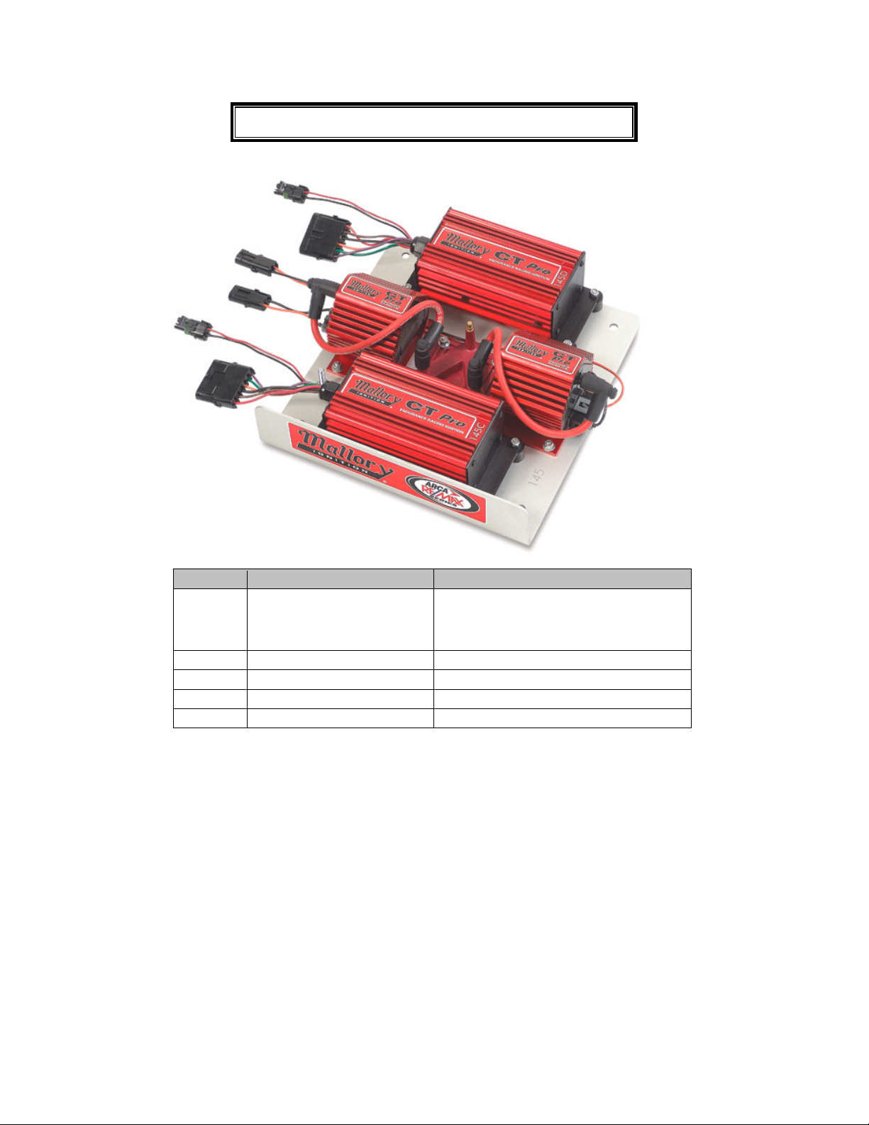
6800M
CT PRO IGNITION SYSTEM
2 CT PRO IGNITION BOXES, 2 CT PRO
IGNITION COILS, 1 DUAL COIL SELECTOR
AND 2 COIL WIRES PRE-MOUNTED ON AN
ALUMINUM PLATE
6864ARCA
CT PRO IGNITION BOX
1 CT PRO IGNITION BOX
30460
CT PRO IGNITION COIL
1 CT PRO IGNITION COIL
29029
DUAL IGNITION PLATE
1 DUAL IGNITION PLATE
29000
DUAL COIL SELECTOR
1 DUAL COIL SELECTOR
Ignition tray
The Ignition tray is made from 1/8” aluminum and has a 12” X 12” footprint. The tray has a 3” tall front lip
for product identification. This lip will be facing the rear of the vehicle and is acceptable to hang off the
edge of the dash. The bend for the lip has a .50” radius so the overall front to back length of the tray is
12.65”
The coil terminals hang off the right and left side edges of the plate by around 1”. Special attention should
be paid when positioning your plate so the coil output terminals are at least 1” away from chassis ground to
prevent possible arching to ground.
The tray has 4, 11/32” holes that are 1” in from the corners of the 12” x 12” footprint. This makes the hole
center spacing 10”. We recommend using 5/16’ or smaller studs and washers to allow for slight variations.
The components are bolted through the plate so there are bolt heads on the bottom of the tray. We
recommend using .25” thick spacers or washers under the plate so the bolt heads do not contact the dash.
Page 2

The overall height from the bottom of the plate bolts to the top of the front ignition box is 3.75” tall.
Special attention should be paid so the corner of the front ignition box does not hit the window of
the car.
Wiring
Each ignition box has a 2-position male weather pack connector for the power and ground wires as well as
a 6-position female weather pack connector for the remainder of the wires. Each coil has a 2-position
female weather pack connector. All connectors exit the tray towards the center of the dash. The tray has a
.25” grounding stud on the left side when looking at the top of the tray. We recommend running a ground
strap from the roll bar to the .25” stud to eliminate the possibility of electrical interference.
The part numbers listed below are for the MATING harnesses (i.e. the vehicle harnesses) that the racecar
will need to mate up to the Mallory CT Pro ignition system.
Main 6-Pin Ignition Box Connector (2 sets required):
Components:
Shell - Delphi P/N 12020926
Pins (6 per shell) - Delphi P/N 12124580
Connector position, wire color and function:
A - Red - Ignition power
B - Brown - Tach signal
C - Black - Coil "-"
D - Orange - Coil "+"
E - Green - Mag P/U "-"
F - Purple - Mag P/U "+"
Coil Jumper Connector (2 sets required):
Components:
Shell - Delphi P/N 12015792
Pins (2 per shell) - Delphi P/N 12124580
Connector position, wire color and function:
A - Black - Coil "-"
B - Orange - Coil "+"
Main Battery Power (2 sets required):
Components
Shell - Delphi P/N 12010973
Pins - Delphi P/N 12124582
Connector position, wire color and function:
A - Red - Main battery power
B - Black - Main Ground
NOTE: The pin "gender" is opposite what would normally be used in Weatherpack assemblies to prevent a
battery power harness from being plugged into a coil harness.
Distributor Wiring
Mallory CT Pro Ignition Boxes were designed to accept one magnetic pickup per ignition box. We
recommend using a dual pickup distributor with each pickup going directly to one ignition box. Paralleling
one magnetic pickup per two CT Pro ignition boxes could result in extremely retarding ignition timing.
If you are using a dual pickup distributor and have a switch to select between each distributor pickup, make
sure it is not wired to parallel one pickup per two ignition boxes.
Page 3

Maximizing RPM limit
There are several engine component or assembly related items that can contribute to the CT Pro Ignition’s
rev limiting circuit activating below the pre-programmed limit of 8,800 RPM. Previously, early rev
limiting issues were not necessarily addressed since most people simply set the rev limiter to a higher rpm
setting. In order to maximize the rev limit of the CT Pro Ignition system, special attention should be paid to
the following engine component or assembly related items.
Distributors-
Cause Excessive end-play causes cylinder to cylinder timing to vary.
Cure Reduce endplay to a minimum, but still allowing for housing expansion. This varies depending
on the length of the housing and its material.
Cause Excessive clearance between the camshaft’s drive gear and the distributor’s driven gear.
Cure Use an oversize gear to reduce the backlash to a minimum. Also, starting with a gear with an
undersize inside diameter and honing it to precisely fit the distributor shaft also will help.
Cause Cylinder to Cylinder timing variation
Cure The greater the variation of the timing from cylinder to cylinder is, the earlier the rev limiting
will occur. The rev limiting function is based on the shortest time between two cylinder firings.
Cause Distributor triggering variations
Cure Different distributors use different internal triggering styles. The more accurate and stable the
trigger signal is, the more accurate the rev limiting will occur.
Camshafts-
Cause Cam Walk
Cure Roller camshafts especially need to have cam walk kept to a minimum. Depending on the design
of the drive being used, this can be controlled by a cam button or thrust plate. Typically, endplay
or walk of .003” to .006” is considered acceptable. While the lobes on a flat tappet camshaft are
tapered, endplay can still be an issue.
Cause Uneven Camshaft Rotation
Cure Minimize the slack or slop in the cam drive whether it is a chain or belt style. The smoother the
camshaft rotates, the less variation in the distributor rotation speed.
While there can be other causes, optimizing the above items, in addition to the general condition of engine
components, can definitely affect an engine’s performance. You may also find some variance based on the
type of testing being performed. You can expect some difference between engine dyno, chassis dyno, and
on-track test results.
 Loading...