

Page 1

HYFIRE® VII Series Electronic Ignition
Controls
Instruction Manual
Part#: 667C
Page 2

GENERAL INFORMATION
The RPM limiter in the HYFIRE®VIIC Ignition System is not recommended as
an engine speed governor. The use of the RPM limiters is not recommended
for applications equipped with a catalytic converter. Similarly, forcing engine
RPM past the RPM limiter continuously for long sustained intervals can cause
problems resulting from fuel build up in the exhaust system that may adversely affect the application.
Ignition Ballast Resistor / Loom Resistance Wire
The HYFIRE®VIIC Ignition Ignition’s performance is not affected by the presence of the factory ignition resistors or ignition ballast resistors in the wire
from the ignition switch. It is not necessary to install ignition ballast resistors
as specified by the instructions for the particular distributor.
Ignition Coils
The HYFIRE®VIIC Ignition Systems is designed to work with Mallory PROMASTER
®
Coil Part No. 28880. Avoid using any other type of ignition coil.
Spark Plug Wires
YOU MUST USE suppression type (carbon core, spiral core) spark plug wire.
We recommend spiral core ignition wire, such as Mallory PRO SIDEWINDER
®
Ignition Wire. Suppression type spark plug wires prevent false triggering and
the possibility of premature ignition or accessory failures.
DO NOT USE solid core (copper core; stainless steel core) spark plug wire
with any electronic ignition system or accessory. Solid core spark plug
wire is one cause of electro-magnetic interference (EMI; ignition noise).
EMI is one cause of false triggering (preignition; spark scatter) and premature ignition or accessory failures.
®
HYFIRE
®
VIIC PRO CD
IGNITION SYSTEM
Part No. 667C
4-12 Cylinder
6 Cylinder Odd-Fire
Notice: This product is legal to sell, distribute or install on vehicles in California. Executive Order D-70-6.
The HYFIRE®VII Pro CD Ignition Controls are not compatible with distributorless systems or positive ground applications.The HYFIRE®VII Ignition System is not designed for marine use.
Spark Plug Gaps
For street applications, use your engine manufacturer’s specifications. For
racing applications, start with your engine manufacturer’s specifications, then
experiment with and closely monitor various gaps to achieve maximum performance.
Electric Welding
Disconnect the HYFIRE®VIIC Ignition System and unplug any distributor harnesses (if possible) before any welding is done on the vehicle.
External RPM Limiters
Mallory RPM Limiter Part Nos. 641-4, 641-6, 641-8, 642, 643 and 644 WILL
NOT function with the HYFIRE
®
VII Ignition Systems.
Mallory PRO TACH®I, IV and IV
The tachometer and shift light will work with the HYFIRE®VII Ignition
Systems. However, the RPM limiter WILL NOT function with the HYFIRE
®
VII
Ignition Systems. Turn the LIMIT RPM knob slightly past 11,000 to prevent
the RPM limiter from interfering with the tachometer’s other functions.
Mounting to a flat surface with shock mounts
•Hold the unit in its mounting position and center punch the mounting pat-
tern on the mounting surface for drilling mounting holes. Drill mounting
holes using a 9/32" drill bit.
•Install the shock mounts into the bottom plate of the unit. Hold the unit in
position where it will be mounted.
• From the backside of the mounting surface, insert the washers and the
1/4-20 nylock nuts onto the shock mount studs. Tighten each nut until
snug.
FORM 1460 (REV. C) 5/00
INSTALLATION INSTRUCTIONS
Mallory-Ignition.com
1
MOUNTING PROCEDURE
Step 1
Disconnect the battery (–) cable to cut power to the system.
Step 2
Select a convenient location to mount the HYFIRE®VII Ignition System. Keep
the unit away from hot engine components or extreme heat such as the
exhaust system and manifolds. Keep the unit away from moving devices,
such as fans, belts and linkages. The location must be dry. Moisture will damage components inside the unit.
Step 3
Page 3
WIRING PROCEDURE
Step 1
Ensure that your vehicle is equipped with a ground cable between the engine
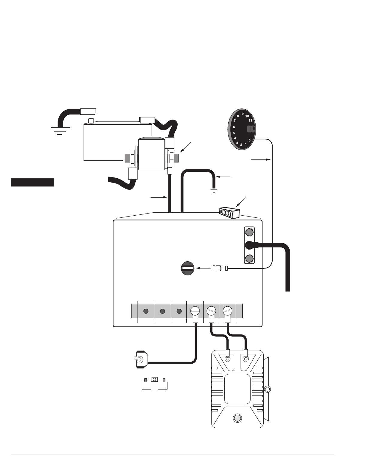
block and firewall (10 gauge or larger is required). Refer to Figure 1 while performing the following steps.
• Connect the HEAVY RED wire to the 12-volt battery (+) post or battery
(+) terminal on the starter solenoid.
• Connect the HEAVY BLACK wire to engine or chassis ground.
• Connect wires between the COIL (+) and (–) terminals.
• Connect 12-volts from ignition switch to the +12V terminal.
• Connect the tach/RPM sensing wire and optional external RPM control to
sockets.
Step 2
When wiring the HYFIRE®VIIC Pro CD Ignition System to an electronic ignition or magnetic pickup, refer to Figures 2 and 3, and trace wires for hookup.
YOU MUST USE suppression type
spark plug wire (carbon core, spiral
core) to help prevent false
triggering and premature ignition
or accessory failures. DO NOT USE
solid core (copper core, stainless
steel core) spark plug wire.
YOU MUST USE Mallory
PROMASTER
®
Coil Part
No. 28880 with this
ignition system.
12V / IGNITION SWITCH
+
-
MALLORY
PROMASTER®
COIL
PART NO. 28880
STARTER
SOLENOID
(–) 12V/BATTERY (+)
ENGINE OR
CHASSIS
GROUND
TO THE STARTER
(TYPICAL)
ENGINE OR
CHASSIS
GROUND
HEAVY RED
IGNITION BALLAST
RESISTOR
AN IGNITION BALLAST RESISTOR
IS NOT REQUIRED FOR PROPER
OPERATION OF THE HYFIRE
®
VIIC.
IF ONE IS ALREADY INSTALLED,
DO NOT REMOVE IT. IF A BALLAST
RESISTOR IS NOT INSTALLED, DO
NOT ADD ONE.
DISCONNECT UNTIL INSTALLATION IS FINISHED
TACH / RPM
SENSING WIRE
12V / BATTERY OR
BATTERY TERMINAL
AT STARTER
SOLENOID
– + – +
HYFIRE® VIIC PR O CD
IGNITION CONTROL
MAGNETIC PICKUP
POINTS
+12V COIL
(REAR PANEL)
TACH
TO HYFIRE® VIIC
IGNITION CONTROL
HEAVY BLACK
ACTIVATION/RELAY
PLUG
FIGURE 1
SEE PAGE 4 FOR
INSTRUCTIONS
ON WIRING THE
RELAY PLUG
NOTE:The Ignition
Control
MUST
be
connected for the
ignition to work.
Mallory-Ignition.com
2
Page 4

– + – +
HYFIRE® VIIC PRO CD
IGNITION CONTROL
MAGNETIC PICKUP
POINTS
+12V COIL
(REAR PANEL)
TACH
JUMPER
WIRE
12V / IGNITION
SWITCH
ENGINE OR
CHASSIS GROUND
BROWN
RED
IGNITION
MODULE
FEMALE
CONNECTOR
GREEN
DISTRIBUTOR WIRE HARNESS
PART NO. 29349
ENGINE OR
CHASSIS
GROUND
ENGINE OR
CHASSIS
GROUND
HEAVY BLACK
(REAR
PANEL)
HEAVY RED
+
-
MALLORY
PROMASTER®
COIL
PART NO. 28880
(-) (+)
12V/BATTERY
HOOKUP HOOKUP TTO A MALLORO A MALLORY UNILITE® IGNITION,Y UNILITE® IGNITION, MA MAGNETIC BREAKERLESS IGNITION OR ELECTRGNETIC BREAKERLESS IGNITION OR ELECTRONICONIC
ADADVVANCE IGNITION (THREE ANCE IGNITION (THREE WIRE:WIRE: RED RED,, BR BROOWN,WN, GREEN) GREEN)
Figure 2Figure 2
YOU MUST USE Mallory
PROMASTER® Coil Part No.
28880 with this ignition system
YOU MUST USE suppression type
spark plug wire (carbon core, spiral
core) to help prevent false
triggering and premature ignition
or accessory failures. DO NOT USE
solid core (copper core, stainless
steel core) spark plug wire.
IGNITION BALLAST RESISTOR
AN IGNITION BALLAST RESISTOR IS NOT
REQUIRED FOR PROPER OPERATION OF THE
HYFIRE
®
VIIC. IF ONE IS ALREADY INSTALLED,
DO NOT REMOVE IT. IF A BALLAST RESISTOR
IS NOT INSTALLED, DO NOT ADD ONE.
TO HYFIRE® VIIC
IGNITION CONTROL
TO HYFIRE® VIIC
IGNITION CONTROL
12V / IGNITION
SWITCH
+
-
MALLORY
PROMASTER®
COIL
PART NO. 28880
MAGNETIC PICKUP DISTRIBUTOR OR CRANK TRIGGER IGNITION
MAMAG+G+
MALLORY BILLET COMPETITION DISTRIBUTOR SERIES NOS. 81 AND 84 ORANGE PURPLE
MALLORY C0MP 9000® SERIES NOS. 96-99 ORANGE PURPLE
MALLORY CRANK TRIGGER OR WIRE HARNESS PART NO. 29787 PURPLE GREEN
MALLORY DISTRIBUTOR WIRE HARNESS PART NO. 29788 ORANGE PURPLE
MALLORY HARNESS PART NO. 29040 RED BLACK
MSD™ CRANK TRIGGER OR WIRE HARNESS PART NOS. 8859 OR 8860 PURPLE GREEN
MSD™ CRANK TRIGGER (OLD STYLE) ORANGE BLACK
MSD™ DISTRIBUTOR ORANGE PURPLE
MOROSO™ CRANK TRIGGER BLACK WHITE
MOROSO™ DISTRIBUTOR ORANGE PURPLE
ACCEL® CRANK TRIGGER BLACK WHITE
CHRYSLER ELECTRONIC DISTRIBUTOR (NON-COMPUTER) ORANGE BLACK
FORD DURASPARK DISTRIBUTOR (NON-COMPUTER) ORANGE PURPLE
GM/DELCO HEI DISTRIBUTOR (NON-COMPUTER) WHITE GREEN
HOOKUP HOOKUP TTO A MAO A MAGNETIC PICKUP DISTRIBGNETIC PICKUP DISTRIBUTUTOR OR CRANK OR OR CRANK TRIGGERTRIGGER
Figure 3Figure 3
MAMAG–G–
MAMAGNETIC PICKUP DISTRIBGNETIC PICKUP DISTRIBUTUTOR OROR OR
CRANK CRANK TRIGGER TRIGGER WIRE COLORSWIRE COLORS
YOU MUST USE Mallory
PROMASTER® Coil Part
No. 28880 with this
ignition system
TWIST WIRES
TOGETHER TO
REDUCE EMI
IGNITION BALLAST RESISTOR
AN IGNITION BALLAST RESISTOR IS
NOT REQUIRED FOR PROPER
OPERATION OF THE HYFIRE
®
VIIC.
IF ONE IS ALREADY INST ALLED, DO
NOT REMOVE IT. IF A BALLAST
RESISTOR IS NOT INSTALLED, DO
NOT ADD ONE.
ENGINE OR
CHASSIS
GROUND
ENGINE OR
CHASSIS
GROUND
HEAVY BLACK
(REAR
PANEL)
HEAVY RED
(-) (+)
12V/BATTERY
– + – +
HYFIRE® VIIC PRO CD
IGNITION CONTROL
MAGNETIC PICKUP
POINTS
+12V COIL
(REAR PANEL)
TACH
NOTE: The Ignition
MUST
MUST
Mallory-Ignition.com
3
Control
connected for the
be
ignition to work.
NOTE: The Ignition
Control
connected for the
ignition to work.
be
Page 5

NOTE: When you apply 12 volts to RPM2, RPM3, RET1, RET2, or RET3 the
display will switch to show that function. If you have both an auxiliary
RPM limit AND a retard selected, the display will show the retard value.
NOTE: When activating Modes 2, 3, 4, 5, or 6, the display will change to
show the active mode. If more than one mode is activated, the higher
mode number will be displayed.
USING THE HYFIRE VIIC FEATURES
Push this button to change the mode
FIGURE 4
Push either of these
buttons to change
the value of the
selected mode.
NOTE: If any button is held down for more than 1/2 second,
the displayed value will change automatically.
Mallory-Ignition.com
4
®
Your Mallory HYFIRE
667C has a number of built-in features that make it
easier to use. This instruction addition tells how to use these built-in features.
First, take a look at the top of the main unit. You'll see that there is an 8-pin
connector beneath the surface, Supplied in the plastic bag that came with
your Hyfire is an 8-pin plug that fits this connector. It has screw clamp terminals that accept up to 14 gauge wire. For best results, use stranded , insulated copper wire, rather than solid wire. The
plug is made so that it will only
fit one way, and has hold down screws at each end.
The connector and mode descriptions are listed below:
RPM switch:
The built-in RPM switch can either turn an electrical load off or on at a selected RPM. See below for more detail.
NC This is the RPM switch (mode 7) relay contact that is normally closed.
In other words, as long as you haven't reached the point where the
RPM switch is active, this contact remains connected to the "common" or "C" terminal. You would use this connection if
, for example,
you wanted to turn something OFF (such as a nitrous system) when
you reached the RPM switch point. See example 1.
C This is the common terminal for the RPM switch (mode 7) relay in the
main unit. It is connected to the RPM switch, where it will switch the
accessory connected to the "NC" terminal OFF, and the accessory connected to the "NO" terminal ON when the RPM switch value is
reached. The "C" terminal can be used to switch either to power or
ground.
NO This is the RPM switch (mode 7) relay contact that is normally
open.
In other words, as long as you haven't reached the point where the
RPM switch is active, this contact isn't connected to the "C" contact.
You would use this contact to turn something ON (such as a shift light
or an air shifter) at a specific RPM. See example 2 and example 3.
RPM Limiters:
The HYFIRE
®
667C has three built-in RPM limiters. Each one has a range of
1000 to 12,800 RPM in 50 RPM steps. On the main display, there is a decimal point on the mode digit. When that decimal point is lit up, the RPM limit
is increased by 50
RPM.
RPM1 (Mode 1) This is the RPM limit that is always active if you haven't
selected any other RPM limit.
RPM2 (Mode 2) This is an auxiliary RPM limiter that is activated when you
apply 12 volts to the "RPM2" terminal on the top-side connector. This
could be a burnout limiter. When selected, it over-rides RPM1 (the
main engine protection RPM limiter). See example 4.
RPM3 (Mode 3) This is the other auxiliary RPM limiter. It also is activated by
12 volts on the "RPM3" terminal on the top-side connector, and overrides both RPM2 and RPM1.
Use this limit as a staging (starting-line)
RPM limiter. See example 5.
High-Speed Timing Retards:
RET1, RET2, RET3 (Modes 4,5,6) These are all high-speed timing retard
functions that are activated by 12 volts on the appropriate top-side connector
terminal. Each higher stage over-rides the lower stages, which means that
you set each stage for exactly the amount of retard you want, rather than
adding up each stage to get the actual retard. See example 6.
See the accompanying illustrations for some examples of how to use the
RPM limiters, the RPM switch, and the timing retard functions.
®
Page 6

NC
C
NO
RPM2
RPM3
RET1
RET2
RET3
COIL
COIL
CONTACT
CONTACT
To Ground
To +12 Volts
To Nitrous System
From Nitrous
Activation Switch
RELAY
Use a relay if you are
switching more than 3-5 amps.
EXAMPLE 1: Using the RPM switch (Mode 7) to turn OFF
a nitrous system at a particular RPM.
NC
C
NO
RPM2
RPM3
RET1
RET2
RET3
To +12 Volts
To Ground
EXAMPLE 2: Using the RPM switch (Mode 7)
to turn on a shift light.
Additional Functions:
The HYFIRE
®
667C has two more functions that can make the ignition installation and setup work better. One of these is the high-speed advance function.
This lets you put small amounts of timing in the engine after the torque peak
to pick up a bit of horsepower. There are three things that need to be set up
for this: the cut-in RPM (mode 9), the maximum advance (mode A), and the
slope (mode 8). The cut-in RPM is the RPM where you want the curve to start
working. The slope is how much the timing will advance every 1000 RPM
after the cut-in RPM. The maximum advance is the highest amount of
advance you want the system to reach.
For example, say that your engine has the torque peak at 6500 RPM, and you
want to add some timing after this. You might want to start adding timing
after 7000 RPM, so this becomes your cut-in speed. If you then want 2
degrees additional timing at 8000 RPM, then the slope would be set for 2
degrees per 1000 RPM. However, let's say that you don't want more than 2
degrees of advance, so you would set the maximum advance at 2 degrees.
See example 7 for more detail.
The other additional function available is trigger compensation, which is set
when the mode indicator is "b". This lets you compensate for the various
delays in ignition timing caused by both electronic and mechanical changes.
To set the trigger compensation, set mode 9 to 5000 RPM, and mode 8 to
zero. What this does is tell the system to start the high-speed advance at 5000
RPM, but with a slope of zero, there should be no advance. Once the system
is set up this way, watch the timing as the engine revs past 5000 RPM. If the
timing does not stay at a steady value (once the 5000 RPM point is reached)
then adjust the compensation value until it is as flat as possible. For example,
if the timing retards slightly as the RPM goes up, increase the compensation
value. If the timing advances slightly as the RPM goes up, decrease the compensation value. NOTE: This function is only valid for RPM above the high-
speed advance cut-in RPM. If you have the high-speed advance cut-in set
above the normal operational range of the motor, the compensation function does nothing.
Once the compensation is set, then the high speed advance settings will be
accurate. The factory setting should be correct for most types of flying magnet type crank trigger systems, and should not normally need to be adjusted
unless you are using a different trigger type.
Number of cylinders selection
The final mode that can be set is mode "C". This allows you to select 4 through
12 cylinder operation. This ensures that the RPML and the timing are proper for
the engine. Mode 6F is special - this is for odd-fire V6 engines ONLY! The cylinder firing spacing should be 45/75 (at the distributor) or 90/150 at the crank.
Mallory-Ignition.com
5
Page 7

NC
C
NO
RPM2
RPM3
RET1
RET2
RET3
To +12 Volts
EXAMPLE 3: Using the RPM switch to activate a
retard stage at a particular RPM.
To roll control switch that supplies
+12 volts when active.
NC
C
NO
RPM2
RPM3
RET1
RET2
RET3
EXAMPLE 4: Burnout RPM Limiter (Mode 2).
To clutch pedal or transbrake switch
that supplies +12 volts when active.
NC
C
NO
RPM2
RPM3
RET1
RET2
RET3
EXAMPLE 5: Staging RPM Limiter.
Mallory-Ignition.com
6
Page 8

To nitrous stage 3 (+12 volts when active)
To nitrous stage 1 (+12 volts when active)
To nitrous stage 2 (+12 volts when active)
NC
C
NO
RPM2
RPM3
RET1
RET2
RET3
EXAMPLE 6: Using the High-Speed timing retard function
with a 3-stage nitrous system.
8
6
4
2
0
ADVANCE
RPM
0
10k8000600040002000
EXAMPLE 7: High Speed Advance Curve (Modes 8 and 9)
SLOPE (Mode 8)
This is how much the timing advances for
every 1000 RPM. This example shows a
slope of 2.0 (2 degrees per 1000 RPM).
CUT-IN (Mode 9)
THIS IS THE RPM WHERE THE TIMING
STARTS TO ADVANCE. THIS EXAMPLE
SHOWS A CUT-IN OF 7.0 (7000 RPM)
MAXIMUM ADVANCE (Mode A)
This example shows a maximum of 2
degrees advance.
Mallory-Ignition.com
7
Page 9

TECHNICAL BULLETIN
Mallory-Ignition.com
8
®
HYFIRE® VIIC AND VIIS
IGNITION SYSTEMS
Part One: Start Retard
The Mallory HYFIRE® VIIC AND VIIS Ignition Systems both have a built-in start retard feature. This retard is
20 degrees at 100 RPM, and decreases to 0 degrees at 500 RPM. This is a very useful feature which
eases the load on the starter motor when used with vehicles that have crank triggered ignition systems or
distributors with locked advances and 30 or more degrees of timing. However, there are applications
where the start retard is either not needed or not wanted. For example, motors with radical camshaft
profiles, large carbs and timing in the 15 to 25 degree BTDC range (Pro Mod motors, for example) may
experience lean-mixture backfiring during startup if the retard feature is active, especially if the temperature is colder than usual.
Current production versions of the HYFIRE® VIIC AND VIIS have a yellow wire loop which comes out of the
back of the ignition box. Cutting this loop eliminates the start retard. Earlier versions of the ignition dont
have this feature, but the start retard can still be shut off. You must either send your ignition in to our service
department for modification, or, if you are attending an NHRA National event, you can bring your ignition to
our race support trailer and have it modified.
CUT YELLOW WIRE LOOP TO
ELIMINATE START RETARD
AFTER CUTTING YELLOW WIRE,
USE SHRINK TUBING TO INSULATE
EXPOSED ENDS
 Loading...