

Page 1
1MALLORY TECHNICAL SUPPORT (775) 882-6600 www.malloryracing.com
E-SPARK™ BREAKERLESS CONVERSION KIT
FOR MALLORY POINT DISTRIBUTORS
NOTE: This product is legal in California only for racing vehicles which may never be operated upon a highway.
INSTALLATION INSTRUCTIONS
FORM 1673 1/07
APPLICATIONS
Part No. 61010M For Left-Hand Rotation 27 Series
Mallory 8 cylinder point automotive
vacuum advance equipped
distributors which use a standard
stack cap (Part no. 209).
Part No. 61011M For Right-Hand Rotation 27
Series Mallory 8 cylinder point
automotive vacuum advance
equipped distributors which use a
standard stack cap (Part no. 209).
Refer to the Mallory Catalog’s distributor application section
if you need a to determine your distributor’s rotation.
PARTS INCLUDE IN THIS KIT:
1 E-Spark™ Plate Assembly
1 Wire Harness
1 Rotor/Shutter Wheel Assembly (PN 322)
1 Wire Connector
1 Grommet
1 Rubber Plug
1 Thrust Button
WARNING
You must install the E-Spark™ Conversion Kit
exactly as shown in these instructions. After the
kit is installed—and before you start the engine—
check all wiring again. Mis-wiring will cause the
E-Spark™ Ignition to fail immediately.
INSTALLATION
Step 1
Rotate the engine to the #1 cylinder firing position.
Remove the distributor cap and note the position of
the rotor. You will need to reference this when you
reinstall the distributor. Remove the distributor from
the engine.
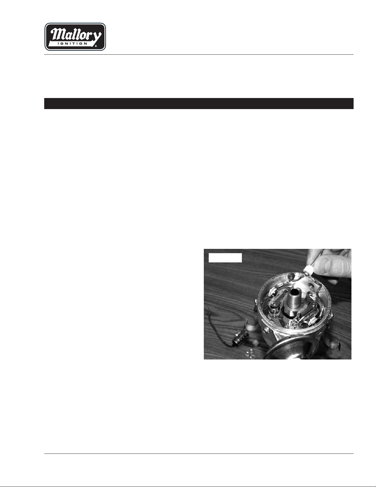
Step 2
Remove the rotor, and then remove the condenser
and bracket. Remove the insulators (Figure 1).
IMPORTANT
All kits listed below must be used with an ignition ballast resistor (or loom resistance wire) to prevent
module failure. If your vehicle is not equipped with a ballast resistor or loom resistance wire, Mallory
Ballast Resistor (Part No. 700) or Mallory Coils 29219, 29450 or 30450 (which are internally ballasted)
may be used.
FIGURE 1
Page 2
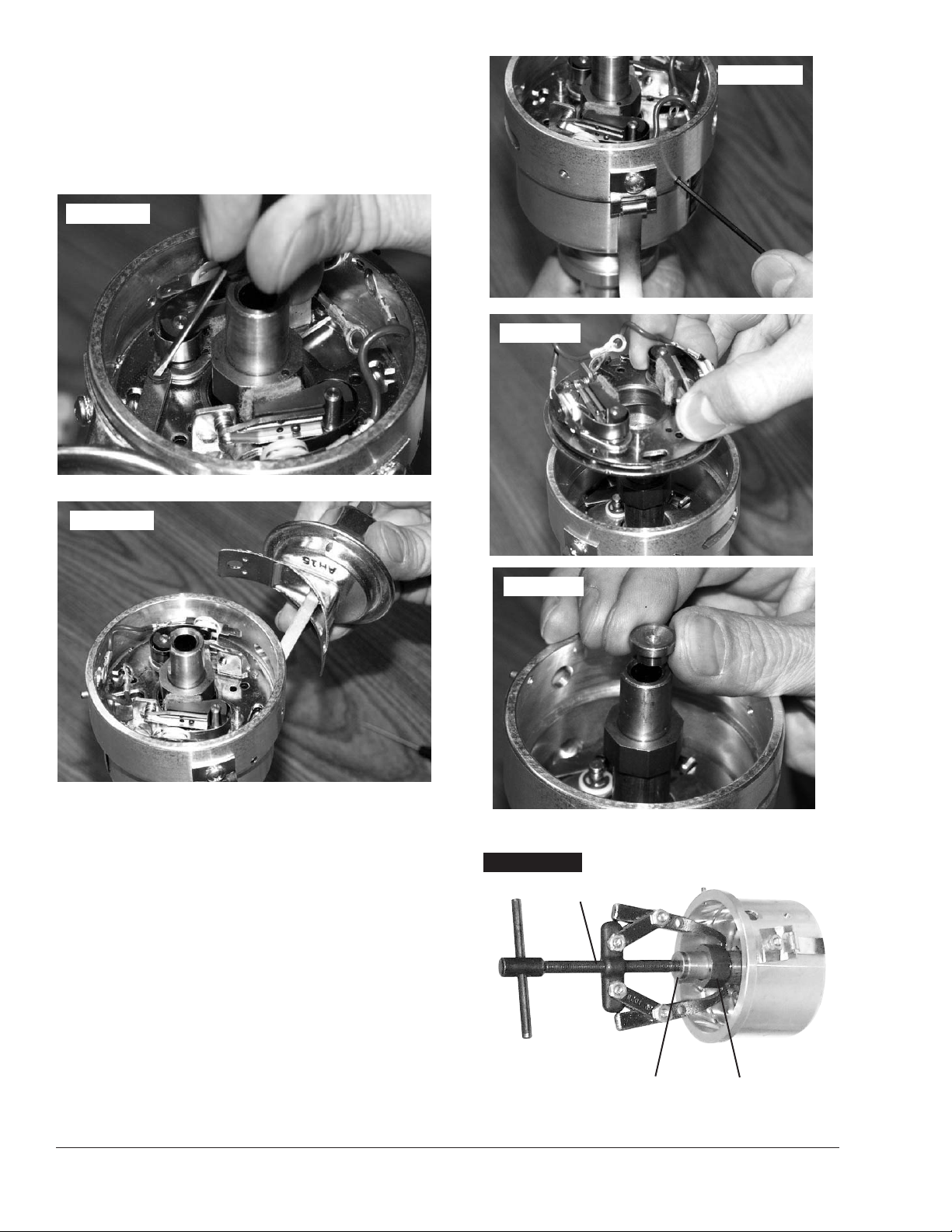
Step 3
Remove the e-clip from the vacuum advance arm
(Figure 2). Remove the 2 screws holding the vacuum
advance chamber from the outside of the distributor
housing and remove the vacuum chamber (Figure 3).
You will re-install it later so do not discard it.
Step 4
Using a 5/64” Allen wrench, loosen the 2 set screws
that hold the point plate assembly into the distributor
housing (Figure 4). You do not need to remove them
completely. Lift the point plate assembly out of the
housing (Figure 5).
Step 5
Place the thrust button into the end of the distributor
shaft (Figure 6). Using a 2 or 3 arm puller and
remove the point cam from the rotor sleeve (Figure 7).
WARNING - Do not try to remove the cam by
prying on it with a screwdriver(s). This will
damage the advance assembly.
MALLORY IGNITION 550 MALLORY WAY, CARSON CITY, NV 89701
2
FIGURE 4
FIGURE 5
FIGURE 6
FIGURE 7
Puller
Thrust Button
Remove button
after cam has
been removed
Cam
FIGURE 3
FIGURE 2
Page 3

Step 6
This step requires you to drill a 3/8” hole in the
distributor housing to accommodate the new wiring
harness. Measure 1” from the existing insulator hole
and the same distance down from the top of the
housing and mark the distributor housing. You will be
slightly offset from the cap locating pin. With a paper
towel inside the housing for shavings, drill the 3/8”
hole now (Figure 8).
Step 7
Clean out any remaining metal shavings left from the
drilling operation using a vacuum, brush, etc. Do not
wash out the housing with the shaft assembly in
place or you will wash the lubrication out of the
centrifugal advance and cause it to fail. If necessary,
you can remove the shaft as an assembly then clean
out the housing.
Step 8
Lower the new plate assembly into the housing
(Figure 9). Use the vacuum advance arm to
determine the position. Tighten the 2 set screws,
reinstall the vacuum advance with the 2 external
screws. Reinstall the e-clip. Use Figure 10 for reference.
Step 9
Install the supplied grommet into the new hole you
drilled (Figure 11) and route the wiring as shown
in Figure 10.
3MALLORY TECHNICAL SUPPORT (775) 882-6600 www.malloryracing.com
FIGURE 8
FIGURE 9
FIGURE 10
Page 4

MALLORY IGNITION 550 MALLORY WAY, CARSON CITY, NV 897014
Step 10
Insert the rubber plug into the existing grommet hole
(Figure 12). This is a tight fit and you may need to pull
it through. Once it is in position, cut the bushing off
flush on the inside (Figure 13).
Step 11
Install the wire grommet. Lubricate the wires with light
oil. Run the wires through the grommet and out of the
distributor housing (see Figure 14).
FIGURE 11
FIGURE 12
FIGURE 13
FIGURE 14
Grommet
E-SPARK Plate
Assembly
Connector
Page 5

5MALLORY TECHNICAL SUPPORT (775) 882-6600 www.malloryracing.com
Step 12
Install the connector onto the wires. Be sure the wires
are in the correct positions (see Figure 15).
Step 13
Install the rotor shutter assembly. Make sure the
rotor/shutter does not rub on the module or wires.
Step 14
Reinstall the distributor using the rotor for a reference.
Reinstall the cap.
Step 15
Connect the wire harness to the connector. Connect
the 3 wires to the correct locations, as shown in
Figures 16 and 17.
Step 16
Set the ignition timing. Start the engine and
recheck timing.
FIGURE 15
Red
Brown
Green
Female Connector
Index Rib
Distributor Wire Harness
Red
Brown
Green
▼
+
COIL
–
FIGURE 16
12V/Ignition
Switch
Distributor Wire Harness
Part No. 29349
Ignition Ballast
Resistor
All other wires originally connected
to the coil (+) terminal
Ignition Module
Female Connector
Engine
Ground
Brown
Green
Red
NOTE: The purpose of an ignition ballast
resistor between the ignition switch (12V)
and the ignition coil positive terminal is to
restrict current flow through the ignition
coil. Failure to use an ignition ballast
resistor will eventually destroy the Ignition
Module.
EXCEPTION: If your vehicle is equipped
with a HYFIRE
®
Electronic Ignition Control
or similar aftermarket ignition control, use
the wiring procedures stated in the instructions
included with the ignition control.
To prevent false triggering and possible
premature ignition failure, you must use
suppression type (carbon core, spiral
core, or radio suppression core) spark
plug wire.
DO NOT USE SOLID CORE (COPPER
CORE OR STAINLESS STEEL CORE)
SPARK PLUG WIRE WITH ANY
ELECTRONIC IGNITION SYSTEM.
EQUIPPED WITH EXTERNAL BALLAST RESISTOR
Page 6

MALLORY IGNITION 550 MALLORY WAY, CARSON CITY, NV 897016
COIL
–
+
EQUIPPED WITH LOOM RESISTANCE WIRE
12V/Ignition
Switch
Engine
Ground
Brown
Green
All other wires originally connected
to the coil (+) terminal
Loom Resistance
Wire
Red
Distributor Wire Harness
Part No. 29349
Ignition Module
Female Connector
FIGURE 17
NOTE: The purpose of loom resistance
wire between the ignition switch (12V) and
the ignition coil positive terminal is to
restrict current flow through the ignition
coil. Failure to use an ignition ballast
resistor will eventually destroy the Ignition
Module.
EXCEPTION: If your vehicle is equipped
with a HYFIRE
®
Electronic Ignition Control
or similar aftermarket ignition control, use
the wiring procedures stated in the instructions included with the ignition control.
To prevent false triggering and possible
premature ignition failure, you must use
suppression type (carbon core, spiral
core, or radio suppression core) spark
plug wire.
DO NOT USE SOLID CORE (COPPER
CORE OR STAINLESS STEEL CORE)
SPARK PLUG WIRE WITH ANY
ELECTRONIC IGNITION SYSTEM.
Page 7

7MALLORY TECHNICAL SUPPORT (775) 882-6600 www.malloryracing.com7
COIL
–
+
12V/Ignition
Switch
Engine
Ground
Brown
Green
All other wires originally connected
to the coil (+) terminal
Red
Distributor Wire Harness
Part No. 29349
Ignition Module
Female Connector
FIGURE 18
EQUIPPED WITH 29219, 29450, OR 30450 COILS ONLY
To prevent false triggering and possible
premature ignition failure, you must use
suppression type (carbon core, spiral core,
or radio suppression core) spark plug wire.
DO NOT USE SOLID CORE (COPPER
CORE OR STAINLESS STEEL CORE)
SPARK PLUG WIRE WITH ANY
ELECTRONIC IGNITION SYSTEM
Page 8

8 www.malloryracing.com
MALLORY IS A DIVISION OF THE MR. GASKET PERFORMANCE GROUP
10601 MEMPHIS AVE. #12, CLEVELAND, OH 44144
216.688.8300 FAX 216.688.8306
FORM 1673
Made in U.S.A.
Printed in U.S.A.
FROM COIL (–) TERMINAL
SOLDER AND INSULATE
SOLDER AND INSULATE
2 EA. 400V 3A DIODES IN SERIES
(RADIO SHACK PART NO. 276-1144)
NOTE POSITION OF BANDS ON DIODES
2 EA. 4.7K, 1/2W RESISTORS IN PARALLEL
(RADIO SHACK PART NO. 271-1124
GRAY WIRE
TO SHIFT BOX
TO ENGINE
GROUND
FIGURE 19
FOR MARINE USE ONLY
After installing your Mallory Electronic
Distributor, the Electronic Shift Assist
(ESA) circuit in your boat must be function
tested.Shifting into or out of gear can be
difficult or impossible if the ESA circuit is
malfunctioning or missing. If you
encounter shifter related problems with
your boat after installing any Mallory distributor, contact the Mallory Technical
Service Department at 216.688.8300.
All Mallory Marine Electronic Ignition Systems in
Outboard Marine Corp (OMC) applications with a shift
box require the gray wire from the coil to the shift box
be modified as follows:
The gray wire from the coil (–) terminal triggers the
shift box. The gray wire should be cut or disconnected at the coil terminal so that the components
shown here can be inserted. Solder all connections
and confirm correct operation, then insulate well,
especially if the boat is being used in salt water.
 Loading...