

Page 1
FORM 1503 6/04
INSTALLATION INSTRUCTIONS
E-SPARK™ BREAKERLESS CONVERSION KIT
FOR MALLORY POINT DISTRIBUTORS
NOTE: This product is legal in California only for racing vehicles which may never be operated upon a highway.
IMPORTANT
All kits listed below must be used with an ignition ballast resistor (or loom resistance wire) to prevent
module failure. If your vehicle is not equipped with a ballast resistor or loom resistance wire, Mallory
Ballast Resistor (Part No. 700) or Mallory Coils 29219, 29450 or 30450 (which are internally ballasted)
may be used.
These kits do not work with vacuum advance distributors.
APPLICATIONS
Part No. 61004M Mallory 8 cylinder point distributors
(automotive and marine) which use
a standard stack cap (Part No. 209
or 209D)
Part No. 61005M Mallory 8 cylinder point distributors
(automotive and marine) which use
a flat cap (Part No. 221 or 221B)
Part No. 61006M Mallory 6 cylinder point distributors
(automotive and marine) which use
a standard stack cap (Part No. 270
or 270B)
Part No. 61007M Mallory 6 cylinder point distributors
(automotive and marine) which use
a mini bowl cap (Part No. 226
or 226B)
Part No. 61008M Mallory 4 cylinder point distributors
(automotive and marine) which use
a standard stack cap (Part No. 271
or 271B)
Part No. 61009M Mallory 4 cylinder point distributors
(automotive and marine) which use
a mini bowl cap (Part No. 225
or 225B)
WARNING
You must install the E-Spark™ Conversion Kit
exactly as shown in these instructions. After the
kit is installed—and before you start the engine—
check all wiring again. Mis-wiring will cause the
E-Spark™ Ignition to fail immediately.
INSTALLATION
Step 1
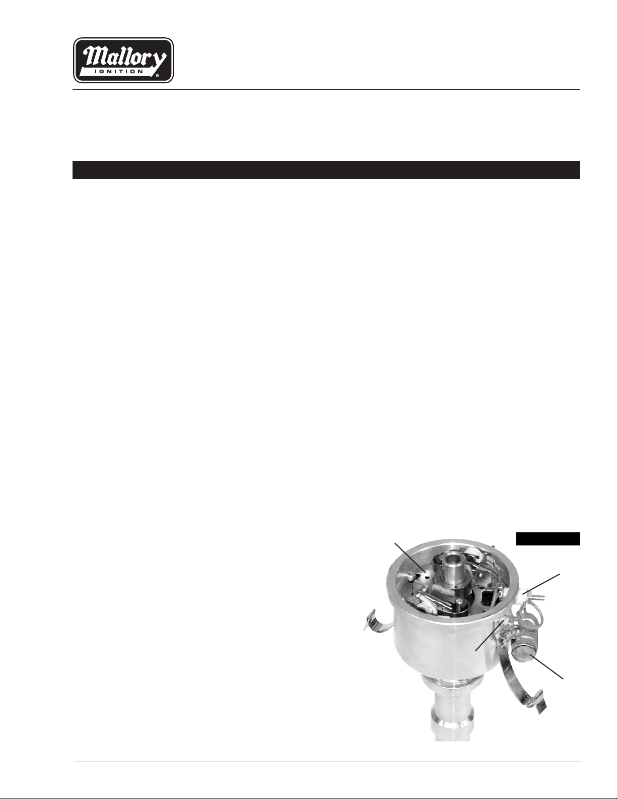
Remove the cap and rotor, then remove the condenser. Remove the plastic insulators (see Figure 1).
Step 2
Loosen the 2 nuts that hold the cap clips/brackets in
place (see Figure 1).
NOTE: To loosen the nuts on a marine distributor,
the aluminum pins in the brackets may need to
be cut in two and removed. Replacement pins
are provided.
Step 3
Remove the point plate assembly by lifting it out of
the housing (see Figure 1).
Point Plate
FIGURE 1
PARTS INCLUDE IN THIS KIT:
1 E-Spark™ Plate Assembly
1 Wire Harness
1 Rotor/Shutter Wheel Assembly (PN 559 contains 2
rotor/shutter wheel assemblies)
1 Wire Connector
1 Grommet, 3-Hole (Marine Approved)
2 Pins, Aluminum
1 Thrust Button
MALLORY IGNITION www.mrgasket.com
Insulators
Cap Clip Nuts
Condenser
1
Page 2
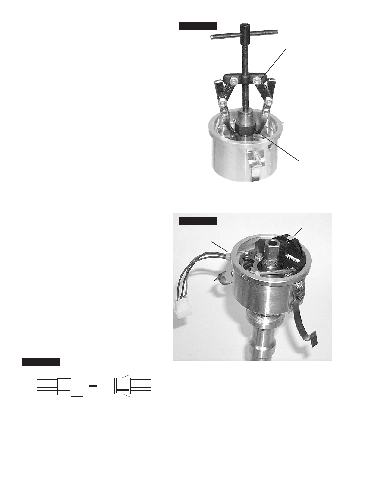
Step 4
Use a 2-arm or 3-arm puller and the thrust button
(provided) to remove the cam from the rotor sleeve
(see Figure 2).
WARNING: Do not try to remove the cam by
prying on it with a screwdriver(s). This will
damage the advance assembly.
Step 5
Install the E-Spark™ plate assembly into the housing.
Make sure that the cut-out in the plate is directly
below the hole in the housing where the wires will exit
(see Figure 3).
Step 6
Tighten the two nuts that hold the cap clips/brackets
in place. This also secures the E-Spark™ plate.
Step 7
Marine Distributors Only
Replace the cap clips using the new aluminum pins
provided.
Step 8
Install the wire grommet. Lubricate the wires with light
oil. Run the wires through the grommet and out of the
distributor housing (see Figure 3).
FIGURE 2
Puller
Thrust Button
Remove button
after cam has
been removed
Cam
Step 9
Install the connector onto the wires. Be sure the wires
are in the correct positions (see Figure 4).
Step 10
Install the rotor/shutter wheel assembly. Make sure
that the rotor is fully seated and that it does not rub
the module wires. Replace the cap.
Step 11
If you removed the distributor to install the E-Spark™
Conversion Kit, reinstall the distributor in the engine.
Step 12
Connect the wire harness to the connector. Connect
the 3 wires to the correct locations, as shown in
Figures 5 and 6.
Step 13
Set the ignition timing. Start the engine and recheck
timing.
FIGURE 4
Female Connector
Red
Brown
Green
▼
Distributor Wire Harness
Red
Brown
Green
FIGURE 3
Grommet
E-SPARK Plate
Assembly
Connector
Index Rib
2
MALLORY TECHNICAL SUPPORT (216)688-8300 www.mrgasket.com
Page 3

COIL
–
+
+
COIL
–
FIGURE 5
EQUIPPED WITH EXTERNAL BALLAST RESISTOR
All other wires originally connected
12V/Ignition
Switch
to the coil (+) terminal
Ignition Ballast
Resistor
Distributor Wire Harness
Part No. 29349
Ignition Module
Female Connector
NOTE: The purpose of an ignition ballast
resistor between the ignition switch (12V)
and the ignition coil positive terminal is to
restrict current flow through the ignition
coil. Failure to use an ignition ballast
resistor will eventually destroy the Ignition
Module.
EXCEPTION: If your vehicle is equipped
with a HYFIRE
®
Electronic Ignition Control
or similar aftermarket ignition control, use
the wiring procedures stated in the instructions
included with the ignition control.
FIGURE 6
EQUIPPED WITH LOOM RESISTANCE WIRE
Red
Green
Engine
Ground
Brown
To prevent false triggering and possible
premature ignition failure, you must use
suppression type (carbon core, spiral
core, or radio suppression core) spark
plug wire.
DO NOT USE SOLID CORE (COPPER
CORE OR STAINLESS STEEL CORE)
SPARK PLUG WIRE WITH ANY
ELECTRONIC IGNITION SYSTEM.
All other wires originally connected
to the coil (+) terminal
12V/Ignition
Switch
Distributor Wire Harness
Part No. 29349
Ignition Module
Female Connector
NOTE: The purpose of loom resistance
wire between the ignition switch (12V) and
the ignition coil positive terminal is to
restrict current flow through the ignition
coil. Failure to use an ignition ballast
resistor will eventually destroy the Ignition
Module.
EXCEPTION: If your vehicle is equipped
with a HYFIRE
®
Electronic Ignition Control
or similar aftermarket ignition control, use
the wiring procedures stated in the instructions included with the ignition control.
Loom Resistance
Red
Brown
Engine
Ground
Green
To prevent false triggering and possible
premature ignition failure, you must use
suppression type (carbon core, spiral
core, or radio suppression core) spark
plug wire.
DO NOT USE SOLID CORE (COPPER
CORE OR STAINLESS STEEL CORE)
SPARK PLUG WIRE WITH ANY
ELECTRONIC IGNITION SYSTEM.
Wire
3MALLORY TECHNICAL SUPPORT (216)688-8300 www.mrgasket.com
Page 4

COIL
–
+
FIGURE 7
EQUIPPED WITH 29219, 29450, OR 30450 COILS ONLY
Ignition Module
Female Connector
12V/Ignition
Switch
Distributor Wire Harness
Part No. 29349
Engine
Ground
To prevent false triggering and possible
premature ignition failure, you must use
suppression type (carbon core, spiral core,
or radio suppression core) spark plug wire.
DO NOT USE SOLID CORE (COPPER
CORE OR STAINLESS STEEL CORE)
SPARK PLUG WIRE WITH ANY
ELECTRONIC IGNITION SYSTEM
Brown
All other wires originally connected
to the coil (+) terminal
Red
Green
FIGURE 8
FOR MARINE USE ONLY
After installing your Mallory Electronic
Distributor, the Electronic Shift Assist
(ESA) circuit in your boat must be function
tested.Shifting into or out of gear can be
difficult or impossible if the ESA circuit is
malfunctioning or missing. If you
encounter shifter related problems with
your boat after installing any Mallory distributor, contact the Mallory Technical
Service Department at 216.688.8300.
FROM COIL (–) TERMINAL
SOLDER AND INSULATE
2 EA. 400V 3A DIODES IN SERIES
(RADIO SHACK PART NO. 276-1144)
NOTE POSITION OF BANDS ON DIODES
MALLORY IS A DIVISION OF THE MR. GASKET PERFORMANCE GROUP
10601 MEMPHIS AVE. #12, CLEVELAND, OH 44144
216.688.8300 FAX 216.688.8306
All Mallory Marine Electronic Ignition Systems in
Outboard Marine Corp (OMC) applications with a shift
box require the gray wire from the coil to the shift box
be modified as follows:
The gray wire from the coil (–) terminal triggers the
shift box. The gray wire should be cut or disconnected at the coil terminal so that the components
shown here can be inserted. Solder all connections
and confirm correct operation, then insulate well,
especially if the boat is being used in salt water.
GRAY WIRE
SOLDER AND INSULATE
2 EA. 4.7K, 1/2W RESISTORS IN PARALLEL
(RADIO SHACK PART NO. 271-1124
TO SHIFT BOX
TO ENGINE
GROUND
Printed in U.S.A.
FORM 1503
Made in U.S.A.
4 www.mrgasket.com
 Loading...