

Page 1
1
UNILITE®DISTRIBUTOR FOR
1952-70 HARLEY DAVIDSON
®
SPORTSTER®MOTORCYCLES
PART NO. 576
NOTE: THIS DISTRIBUTOR WILL ALSO FIT 1930-73 FLATHEAD (45 AND UL).
INSTALLATION INSTRUCTIONS
FORM 1479 (REV. B) 08/03
GENERAL INFORMATION
Any coil or combination of coils with a total primary
resistance of at least 2.0 ohms can be used with this
distributor. We recommend a 2-3 ohm coil for racing
and a 3-4 ohm coil for street use. A coil with 4-5 ohms
resistance may be used. However, performance
may be reduced, even in street applications.
NOTE: Check the charging system and make sure
that it is producing no more than 16 volts.
We recommend a spark plug gap of .040" when using
a 2-3 ohm coil. A gap of .030" is recommended when
using a 3-4 ohm coil.
An optional spring kit (PN 29014) is available for this
distributor. The kit gives you a choice of 14 different
advance curve settings.
INSTALLATION
Step 1
Turn the ignition switch to the off position. With the
point distributor still in place and correctly timed,
rotate the engine until the points begin to open on
the front cylinder lobe. The front cylinder lobe is the
narrower of the two.
If the point distributor is not installed, rotate the engine
to the beginning of the compression stroke. Locate the
timing hole. Continue rotating the engine until the
advance mark is visible through the timing hole.
Step 2
Remove the ground cable from the battery. Remove
the point wire at the coil. Remove the point distributor.
MALLORY TECHNICAL SUPPORT (775) 882-6600 Visit us on the web at: www.mrgasket.com
IMPORTANT
A 1952-70 Sportster®DISTRIBUTOR CLAMP (ORIGINAL OR AFTERMARKET) IS REQUIRED
TO INSTALL THIS DISTRIBUTOR. BECAUSE THE UNILITE®MODULE USED WITH THIS
DISTRIBUTOR REQUIRES 7-16 VOLTS, A 12 VOLT ELECTRICAL SYSTEM IS ALSO REQUIRED.
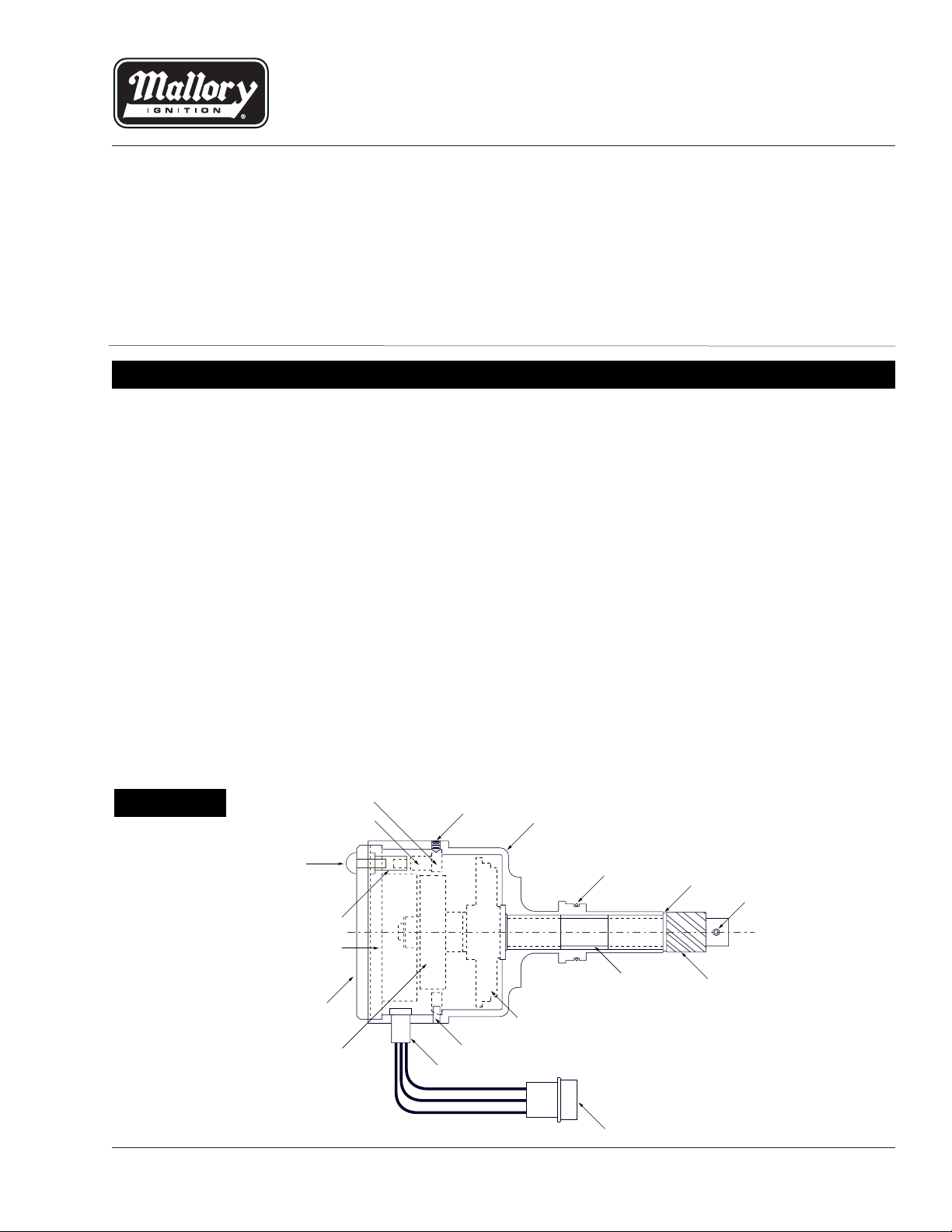
FIGURE A
HOUSING
ADAPTER RING
STANDOFF
SCREW
SLEEVE NUT
SHAFT
SET SCREW
COVER
UNILITE PLATE ASSY
SHUTTER WHEEL
GROMMET
PIN
YH ADVANCE
O-RING
GEAR
ROLL PIN
WASHER
CONNECTOR
Page 2

MALLORY IGNITION 550 MALLORY WAY, CARSON CITY, NV 897012
Step 3
Remove the cover from the Mallory distributor by
removing the two screws. Rotate the shaft until the
arrow on the UNILITE®plate points approximately
at the “X” on the shutter wheel. Install the Mallory
distributor in the engine. Be sure that the distributor
wires exit on the side closest to the cylinders.
Step 4
Install a distributor clamp. Do not tighten the clamp
at this time.
Step 5
Turn the shutter wheel by hand to test the advance.
The shutter wheel should rotate about 10º and snap
back when released. Using one hand, rotate the
shutter wheel to the fully advanced position and hold.
Using your other hand, rotate the housing until the
arrow lines up with the “X”. Tighten the distributor
clamp. Release the shutter wheel. The timing should
now be close enough to start the engine.
Step 6
Connect the wires (See Figures C and D).
MALLORY IS A DIVISION OF THE MR. GASKET PERFORMANCE GROUP
550 MALLORY WAY, CARSON CITY, NEVADA 89701
(775) 882-6600 FAX (775) 887-4326
www.mrgasket.com
FORM 1479
(REV. B) 08/03
Made in U.S.A.
Printed in U.S.A.
SINGLE PLUG HEADS
GREEN RED
2 TO 4 OHM
BROWN
GROUND
12 VOLTS FROM IGNITION SWITCH
FIGURE B
FIGURE C
DUAL PLUG HEADS
GREEN
JUMPER
12 VOLTS FROM IGNITION SWITCH
RED
BROWN
GROUND
1 TO 2 OHM 1 TO 2 OHM
FIGURE D
NOTE: Arrow and X in photo have been enlarged for clarity.
Step 7
Replace the Mallory cover and install the two screws
to hold it in place.
Start the engine and check the timing with a
timing light.
NOTE: When checking the timing, engine RPM
must be above 2000 for accurate timing results.
Page 3

With the Module wired to the coil like it’s ready to
run. Take the cap off and position the Module so
you can see it. Turn the key on, test voltage on the
negative side of the coil, which is where the green
wire attaches to the coil.
To do this the Red lead from the voltmeter will go to
the Green wire on the coil. The Black wire from the
voltmeter will go to ground. Set the voltmeter for
12 volts DC.
With the ignition switch ON you should have about
12 volts. Then take a card or match book and place it
in slot of the module to block the photo optics of the
module. (See Pictures) The voltage should drop to
1-2 volts. Remember it’s an infrared LED you won’t
see it.
If the test results are as follows the Module will need
to be replaced:
(a) Voltage does not drop to 1-2 volts when
optics blocked.
(b) Voltage always stays below 2 volts, blocked
or not.
(c) Voltage only drops above 2 volts, the higher
above 2 volts the weaker the spark.
Possible causes are:
• Faulty charging system: stuck or shorted
regulator, bad ground, dead cell or defective
battery, defective stator or generator.
• Faulty ignition switch, direct shorts in
electrical system.
• Faulty starting system: starter drag.
• Trying to start motor with battery charger
hooked up.
• Non-suppression spark plug wires (copper
or stainless solid core wires). Spark plug wires
must be Spiral Core or Graphite Core
suppression wire.
• Welding on the Bike with Module still hooked
up (unplug the white connector to the Module
before welding).
• Improper coil, use 2-4 ohm coil
(check installation instruction).
If you must replace the Module, replace it
with Mallory Part # A605.
If after completing the test you still have
questions 216-688-8300 ext. 5
TEST PROCEDURE FOR
UNILITE
®
AND E-SPARK
®
FOR MOTORCYCLES
 Loading...