

Page 1

FORM #1321 (REV. B) 8/99
INSTALLATION INSTRUCTIONS
®
MAGNETIC BREAKERLESS
CONVERSION KIT
FOR MALLORY DISTRIBUTOR S
IMPORTANT
This conversion kit must be used with an ignition ballast resistor (or loom
resistance wire) to prevent module failure. If your vehicle is not equipped
with a ballast resistor or loom resistance wire, Mallory Ballast Resistor (Part
No. 700) may be used.
APPLICATIONS
NOTE: These kits do not work with vacuum advance distributors.
Part No. 564-R Mallory 8 cylinder point distributors (automotive and marine) which use a
standard stack cap (Part No. 209 or 209D) and rotate clockwise (RH)
Part No. 564-L Mallory 8 cylinder point distributors (automotive and marine) which use a
standard stack cap (Part No. 209 or 209D) and rotate clockwise (LH)
NOTE: These kits will only work in distributors which use a YH advance mechanism. Look
for an H at the end of the part number located on a tag on the distributor bowl.
PARTS INCLUDE IN THIS KIT:
1 Sleeve/Plate Assembly
1 Magnetic Module
1 Rotor
1 Bag Hardware
INSTALLATION
Step 1
Remove the cap and rotor, then remove the
condensor.
Step 2
Remove the plastic insulators (see Figure 1).
Step 3
Loosen the 2 nuts that hold the cap clips/brackets in
place (see Figure 1). NOTE: To loosen the nuts on
a marine distributor, the aluminum pins in the
brackets may need to be cut in two and removed.
Replacement pins are provided.
Step 4
Remove the point plate assembly by lifting it out of
the housing (see Figure 1).
Step 5
See Figure 2.
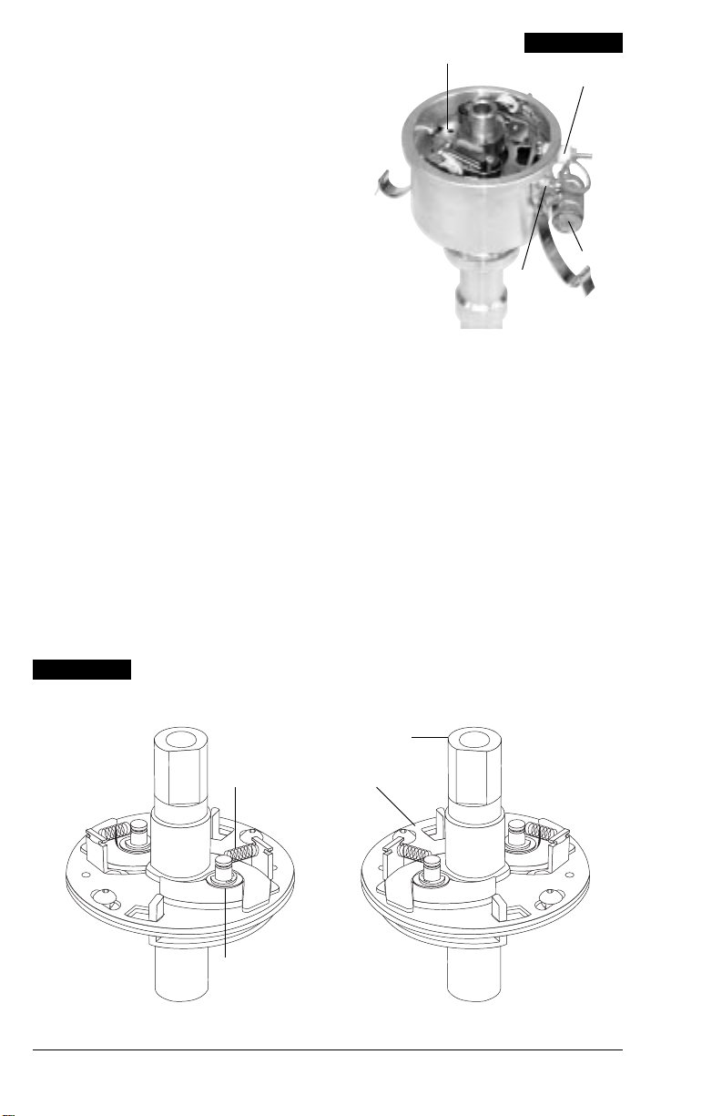
Remove the advance springs. Remove the two Eclips. Remove the advance weights and bushings.
Step 6
Lift the sleeve and advance plate up and off the
distributor shaft.
NOTE: Between the distributor shaft drive plate and
the advance plate is a thrust washer. Sometimes
the thrust washer sticks to the bottom of the advance plate during removal of the sleeve and
advance plate. Make sure you install the thrust
washer on the distributor shaft drive plate. A replacement thrust washer is provided if your thrust
washer needs replacement.
0
Page 2
Step 7
Lubricate the distributor shaft and the top and bottom
of the thrust washer. A light coating of moly lube/
grease or similar lubricant is acceptable. Install the
reluctor sleeve and advance plate on the distributor
shaft. Install the felt pad into the top hole of the
reluctor sleeve.
Step 8
Install the advance weights and bushings. Install the
two E-clips. Install the advance springs.
Point Plate
FIGURE 1
Insulators
Step 9
See Figure 3.
Install the module assembly into the housing. Make
sure that the cut-out in the plate is directly below the
hole in the housing where the wires will exit.
Step 10
Tighten the two nuts that hold the cap clips/brackets
in place. This also secures the module plate.
Marine Distributors Only
Replace the cap clips using the new aluminum pins
provided.
Step 11
Install the wire grommet. Lubricate the wires with light
oil. Run the wires through the grommet and out of the
distributor housing.
Step 12
Put the three wires into the female connector:
GREEN WIRE in hole #1
BROWN WIRE in hole #2
RED WIRE in hole #3
FIGURE 2
YH ADVANCE
Cap Clip
Condensor
Nuts
Plug the female connector into the distributor wire
harness. See Figure 3.
Step 13
Connect the three wires of the wire harness to the
correct locations as indicated in Figures 5 and 6.
Step 14
Set the pickup gap (see Figure 4).
Step 15
If the distributor was removed from the engine,
reinstall. Install the cap, rotor, and plug wires. Static
time the engine. Start the engine and recheck the
timing.
Sleeve
Advance Spring
E-Clip
Advance Plate
LEFT HAND ROTATION RIGHT HAND ROTATION
2
Page 3

FIGURE 3
FIGURE 4
Red
Brown
Green
FIGURE 5
TO SET MAGNETIC
PICKUP GAP:
FEMALE
CONNECTOR
INDEX RIB
Reluctor
Loosen the two
magnetic pickup nuts
DISTRIBUTOR
WIRE HARNESS
Red
Brown
Green
Set gap between .007" - .010" when a
tooth on the reluctor is pointing
directly at the center of the metal
pole on the magnetic pickup. Tighten
the magnetic pickup nuts.
2
Page 4

FIGURE 6
WIRING WITH BALLAST RESISTOR
ALL OTHER WIRES ORIGINALLY CONNECTED
TO THE COIL (+) TERMINAL
12V/IGNITION
SWITCH
DISTRIBUTOR WIRE HARNESS
PART NO. 29349
RED
IGNITION BALLAST
RESISTOR
IGNITION MODULE
FEMALE CONNECTOR
NOTE: The purpose of an ignition ballast resistor
between the ignition switch (12V) and the ignition coil
positive terminal is to restrict current flow through the
ignition coil. Failure to use an ignition ballast resistor
will eventually destroy the Ignition Module.
EXCEPTION: If your vehicle is equipped with a HYFIRE
Electronic Ignition Control or similar aftermarket ignition
control, use the wiring procedures stated in the
instructions included with the ignition control
FIGURE 7
IGNITION MODULE
FEMALE CONNECTOR
NOTE: The purpose of loom resistance wire between
the ignition switch (12V) and the ignition coil positive
terminal is to restrict current flow through the ignition
coil. Failure to use an ignition ballast resistor will
eventually destroy the Ignition Module.
EXCEPTION: If your vehicle is equipped with a HYFIRE
Electronic Ignition Control or similar aftermarket ignition
control, use the wiring procedures stated in the
instructions included with the ignition control.
WIRING WITH LOOM RESISTANCE WIRE
12V/IGNITION
SWITCH
DISTRIBUTOR WIRE HARNESS
PART NO. 29349
GROUND
ENGINE
GROUND
®
ENGINE
®
BROWN
To prevent false triggering and possible premature
ignition failure, you must use suppression type (carbon
core, spiral core, or radio suppression core) spark plug
wire.
DO NOT USE SOLID CORE (COPPER CORE OR
STAINLESS STEEL CORE) SPARK PLUG WIRE WITH
ANY ELECTRONIC IGNITION SYSTEM.
ALL OTHER WIRES ORIGINALLY CONNECTED
TO THE COIL (+) TERMINAL
BROWN
To prevent false triggering and possible premature
ignition failure, you must use suppression type (carbon
core, spiral core, or radio suppression core) spark plug
wire.
DO NOT USE SOLID CORE (COPPER CORE OR
STAINLESS STEEL CORE) SPARK PLUG WIRE WITH
ANY ELECTRONIC IGNITION SYSTEM.
GREEN
LOOM RESISTANCE WIRE
RED
GREEN
–
COIL
–
+
+
COIL
MALLORY IS A DIVISION OF THE MR. GASKET PERFORMANCE GROUP
550 MALLORY WAY, CARSON CITY, NV 89701
(775) 882-6600 FAX (775) 887-4326
www.mrgasket.com
FORM #1321
REV. B (8/99)
MADE IN U.S.A.
PRINTED IN U.S.A.
4
 Loading...