

Page 1

1MALLORY IGNITION www.mrgasket.com
COMP PUMP®SERIES 250
ELECTRIC FUEL PUMP
PART NOS. 5250 AND 5250A
INSTALLATION INSTRUCTIONS
FORM 1038 (REV. F) 11/04
GENERAL INFORMATION
The COMP PUMP®250 Series Electric Fuel Pump is a high
volume fuel pump designed for serious racing applications.
The pump is factory set to approximately 15 PSI. In all
cases, this fuel pump must be used with a fuel pressure
regulator. We recommend the following:
Standard Regulator
Mallory 4 Port Regulator Part No. 4200 (gasoline)
Part No. 4201 (alcohol)
Return Style Regulator
Mallory 5 Port Regulator Part No. 4300M (gasoline)
Part No. 4301M (alcohol)
This fuel system must have a fuel return line going to the fuel
tank. We recommend at minimum a #8 AN (1/2") line.
If you use a standard fuel pressure regulator, not a return
style, run the fuel return line from the fuel pump’s fuel return
port. Use the 3/4"-16 thread x #8 AN flare fitting provided to
connect your #8 AN line.
If you use a return style fuel pressure regulator, run a #10 AN
fuel return line from the fuel pressure regulator’s fuel return
port and install a 3/4"-16 thread plug and o-ring in the fuel
pump’s fuel return port. You can find a 3/4"-16 thread plug
at most hardware stores. Do not try to adjust the bypass
adjustment - pump damage may result.
Be sure to install a suitable fuel filter (maximum 100 micron)
between the fuel tank and the fuel pump. Mallory COMP
FILTER
®
Series Part Nos. 3140 or 3500 are recommended.
This prevents debris from becoming wedged in the fuel
pump’s Gerotor and locking it. An additional filter(s)
(maximum 40 micron) should be installed just before
the carb(s).
PARTS INCLUDED IN THIS KIT:
1 COMP PUMP®Series 250 Electric Fuel Pump
3 Fittings, 3/4" - 16 x #8 AN Flare
3 O-rings, Nitrile 0.644ID x 0.087 thickness
NOTE: DO NOT OPERATE THIS PUMP
WITHOUT FUEL EXCEPT FOR BRIEF
PERIODS WHILE PRIMING
SPECIFICATIONS
Maximum recommended operating pressure: 20 PSI
(factory set at approximately 15 PSI)
Maximum dry suction lift: 3 feet. This is maximum distance
above the fuel level in the fuel tank that the fuel pump will
prime itself.
Oil pressure switch rating: 15 AMP
Fuel pump over current protection: 15 AMP fuse
Fuel application: Part No. 5250, Gasoline; Part No. 5250A,
Alcohol / Methanol
Page 2
2 www.mrgasket.com MALLORY IGNITION
CARB
FUEL
FILTER
REGULATOR
FUEL
PUMP
FUEL RETURN
FUEL RETURN
PORT
FUEL
FILTER
FUEL
TANK
FIGURE 1
FIGURE 2
FIGURE 3
MOUNTING PROCEDURE
Step 1
Mount the pump as close as possible to the fuel tank in a
well ventilated area with minimal exposure to road debris.
Avoid exposing the pump and fuel lines to moving parts
and hot surfaces, such as the exhaust system.
The pump should be mounted at tank level or below.
NOTE: Increasing distance between pump and tank will
decrease pump efficiency.
Step 2
Using the pump mounting bracket as a template, locate
mounting holes on a solid member, such as the vehicle
chassis. Drill clearance holes for 5/16" bolts. NOTE: To
ensure against a potential fire hazard from pump
flooding, mount the pump in a vertical position with
the motor on top.
See Figure 1.
Step 3
To prolong pump life and efficiency, a high volume fuel filter
such as the Mallory COMP FILTER
®
Series 500 Fuel Filter
(Part No. 3500) must be installed between the pump and
fuel tank. Connect #8 AN fuel lines as shown in Figure 2 for
Standard Regulator or #10 AN lines as shown in Figure 3
for Return (Bypass) Style Regulator.
Step 4
Be sure to install one of the Mallory High Volume Fuel
Pressure Regulators between the pump and carburetor.
For maximum efficiency, mount the pressure regulator
as close as possible to the carburetor. See instructions
packaged with the pressure regulator. Make sure all
fittings are tight so that air cannot enter the system.
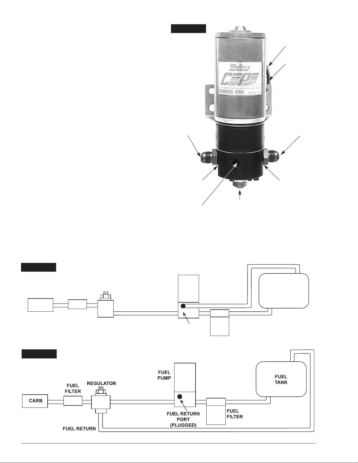
(WITH STANDARD FUEL PRESSURE REGULATOR)
(WITH REGULAR STYLE FUEL PRESSURE REGULATOR)
FUEL OUTLET
3/4" - 16 (#8AN)
FUEL INLET
3/4" - 16 (#8AN)
FUEL RETURN 3/4" - 16
(MUST BE PLUGGED
WHEN USING A RETURN
[BYPASS] STYLE
REGULATOR
NITRILE O-RING
NITRILE O-RING
BYPASS ADJUSTMENT
NOTE: Bypass pressure above
20 psi will make the pump draw
more current and significantly
reduce pump life.
RED (+)
BLACK (–)
Page 3

3MALLORY IGNITION www.mrgasket.com
IGNITION SWITCH
OIL PRESSURE SWITCH
TO ACCESSORIES
TO COIL (+)
GROUND
GROUND
COMMON
FUSE (15 AMP)
NORMALLY
OPEN
NORMALLY
CLOSED
FROM
VEHICLE
BATTERY
STARTER
VEHICLE
BATTERY
FUEL
PUMP
RED (+)
BLACK (-)
FIGURE 5
FIGURE 4
WIRING PROCEDURE
Wiring the pump to an oil pressure switch provides power
only when the ignition switch is on and the engine is
running. This prevents the pump from running if your
engine stalls. Use 12 gauge wire or larger and be sure to
disconnect the battery ground cable before wiring the
pump. Refer to Figure 4 when connecting the pump to
an oil pressure switch.
The pump may be wired directly to the ignition switch “ON”
terminal and grounded to the frame or battery. Refer to
Figure 5 when connecting the pump to the ignition switch
“ON” terminal.
IGNITION SWITCH
FROM
VEHICLE
BATTERY
TO ACCESSORIES
TO COIL (+)
FUSE (15 AMP)
RED (+)
FUEL
PUMP
BLACK (-)
GROUND
Page 4

4 www.mrgasket.com
MALLORY IS A DIVISION OF THE MR. GASKET PERFORMANCE GROUP
10601 MEMPHIS AVE. #12, CLEVELAND, OH 44144
216.688.8300FAX 216.688.8306
FORM 1038
(REV. F) 11/04
Made in U.S.A.
Printed in U.S.A.
FIGURE 6
18
19
20
21
22
23
24
9
10
11
14
15
16
17
12
13
1
2
3
4
5
6
7
8
MAINTENANCE –
PUMP DISASSEMBLY
If your pump fails to produce adequate pressure or
volume, it may require cleaning. Follow the steps below to
disassemble and clean your Mallory Electric Fuel Pump.
Refer to Figure 6 while performing the following steps.
Step 1
Remove the pump from the vehicle and clean pump exterior.
Place the pump on its side on a clean work surface. Scribe
or draw a line across the pump housing, port plate and fuel
chamber so that you can reassemble the pump correctly.
Step 2
Remove the two fuel chamber screws from the bottom of the
pump. Remove fuel chamber and port plate from the pump.
NOTE: Do not drop the gerotor from the pump cavity.
Step 3
Place your hand beneath the gerotor and hold the pump in
an upright position. The gerotor should slide out of the
pump and into your hand.
Step 4
To disassemble the fuel chamber, first remove the lock nut
and adjusting screw, then turn the fuel chamber over so that
the diaphragm spring falls into your hand. Remove the four
screws holding the diaphragm cap to the fuel chamber.
Remove the diaphragm cap, diaphragm, and damper spring
from the fuel chamber.
Step 5
Clean the gerotor and reinstall it in the pump housing.
Inspect the O-ring and gasket, and replace them if
necessary. Inspect the diaphragm for any small tears or
bubbles in the surface, and replace it if necessary. Inspect
the gerotor housing and port plate for wear. If the generator
has worn through the plating, return the pump to Mallory
for repair.
Step 6
Assemble the pump in the reverse order that you
disassembled it. Test bypass pressure. Adjust bypass
so that pump is producing between 13 and 20 psi.
1. JAM NUT
2. ADJUSTING SCREW
*3. PRESSURE ADJUSTMENT SPRING
*4. CAP SCREW (4)
5. REGULATOR CAP
*6. GASOLINE DIAPHRAGM
ALCOHOL/METHANOL DIAPHRAGM
*7. FUEL CHAMBER SCREW
*8. DAMPER SPRING
9. FUEL CHAMBER
*10. FUEL CHAMBER GASKET
11. PORT PLATE
12. GEROTOR
*13. GEROTOR BUSHING KEY
*14. GEROTOR BUSHING
*15. O-RING
16. GEROTOR HOUSING
*17. SEAL
*18. BRACKET VIBRATION GASKET
19. BRACKET
20. MOTOR HOUSING NUT (2)
21. MOTOR ADAPTER
22. SPRING WASHER
23. MOTOR ADAPTER SCREW (2)
24. MOTOR
*THESE PARTS ARE INCLUDED IN SEAL / DIAPHRAGM KITS
PART NO. 3171 FOR GASOLINE
PART NO. 3172 FOR ALCOHOL
IMPORTANT: Turn fuel chamber screws by hand until they
contact the chamber. Then torque to 24 inch/pounds
 Loading...