

Page 1
FORM 1085 (REV. F) 01/12
INSTALLATION INSTRUCTIONS
COMP PUMP® SERIES 110FI
ELECTRIC FUEL PUMP
PART NO. 5110FI
NOTE: DO NOT RUN THIS PUMP WITHOUT FUEL (EXCEPT FOR BRIEF PERIODS WHILE PRIMING).
PARTS INCLUDED IN THIS KIT
1 COMP PUMP® 110FI Series Electric Fuel Pump
2 Fittings, 3/4-16 x #8 AN Flare
2 O-rings, Nitrile 0.644ID x 0.087THK
SPECIFICATIONS
GENERAL INFORMATION
The COMP PUMP® 110FI Series Electric Fuel Pump is
a high pressure fuel pump designed for fuel injection
applications. In all cases, this fuel pump must be used
with a return style (bypass) fuel pressure regulator.
Using the pump with any other type of regulator (or
no regulator) will result in severe fuel pump damage.
We recommend the following return style fuel pressure
regulators:
4–25 PSI Part No. 4307M (gasoline or alcohol)
30–100 PSI Part No. 4305M (gasoline or alcohol)
As stated earlier, you must use a return style (bypass)
regulator with this fuel pump. You must install a fuel
return line between the fuel return port of the regulator
and the fuel tank. We recommend at minimum a #8
AN (1/2”) fuel return line.
An air bleed system is located at the bottom of the
fuel pump to assist in priming the fuel pump. The air
bleed line is plumbed to the fuel return line. If you are
running 10 PSI fuel pressure or less, install a 1/8” NPT
plug in the air bleed port, When installing the plug, use
a thread sealant compound on the fitting threads)
purchase 1/8” NPT fittings or plugs, as well as thread
sealant compound, at any hardware store). Do not use
thread sealing tape. Thread sealing tape can get into
the Gerotor and lock the pump. Also, do not overtighten
the fitting. This could damage the pump housing.
Maximum recommended operating pressure:
75 PSI continuous, 100 PSI intermittent
Fuel pump thread sizes: Inlet/outlet, 3/4-16 (#8AN)
Air bleed system, 1/8” NPT
Recommended fuel line size: 1/2” (or #8AN)
Current draw: 12 AMP Typical
Oil pressure switch rating: 25 AMP
Fuel pump over current protection: 25 AMP fuse
Fuel application: Gasoline
Use Seal/Repair Kit Part No. 3168 to convert the
COMP PUMP® SERIES 110FI Electric Fuel Pump to
alcohol/methanol.
Be sure to install a suitable fuel filter (max. 100 micron)
between the fuel tank and the fuel pump, such as the
Mallory COMP FILTER® Series Part Nos. 3140 or 3500.
This prevents debris from becoming wedged in the
fuel pump’s Gerotor and locking it.
An additional fuel filter (maximum 10 micron, such as
the COMP FILTER® 160 Series Part No. 3160) must be
installed between the fuel pump and the injectors. This
prevents debris from clogging the injectors.
SERVICE PARTS:
Part No. 3167 Seal/Repair Kit, Gasoline (may be used
to convert alcohol/methanol
fuel pumps to
gasoline)
Part No. 3168 Seal/Repair Kit, Alcohol/Methanol (may
be used to convert gasoline
fuel pumps to alcohol/methanol)
1MALLORY IGNITION www.malloryracing.com
Page 2
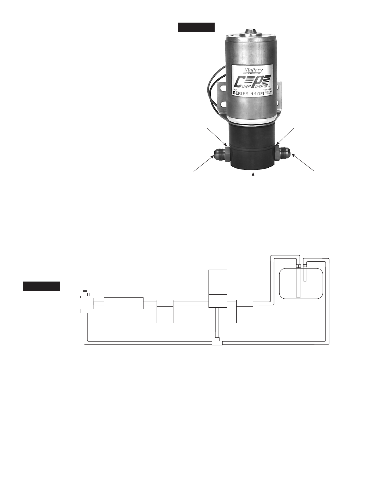
FUEL INJECTION
FUEL
FILTER
FUEL
FILTER
REGULATOR
FUEL
PUMP
FUEL RETURN AIR BLEED
FUEL
TANK
COMP�
FILTER
P/N 3160
COMP�
FILTER
P/N 3140
or 3500
MOUNTING PROCEDURE
Step 1
Mount the pump as close as possible to the fuel tank
(at or below the level of the fuel tank pickup) in a well
ventilated area with minimal exposure to road debris.
Avoid exposing the pump and fuel lines to moving parts
and hot surfaces, such as the exhaust system. NOTE:
Increasing distance between the pump and tank will
decrease pump efficiency.
Step 2
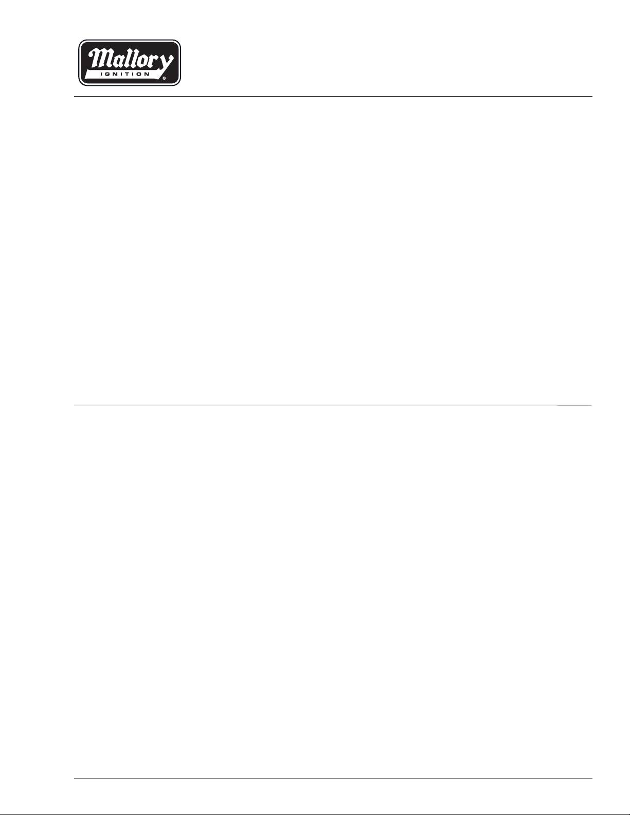
Using the pump mounting bracket as a template, locate
mounting holes on a solid member, such as the vehicle
chassis. Drill clearance holes for 5/16” bolts. See
Figure 1.
Step 3
Connect 1/2” or larger fuel lines as shown in Figure 2.
The 1/8” NPT outlet on the bottom of the pump is for
an air bleed line to assist pump priming. This air bleed
line is not necessary if the regulated pressure of your
system is less than 10 psi. NOTE: Use a thread sealant
compound on the fitting threads. Don’t use thread
sealing tape because it could get into the Gerotor
and lock the pump.
Step 4
Your system must have a Return Style Fuel Pressure
Regulator near the injection system. See the General
Information section on page 1 for recommendations.
For maximum efficiency, mount the pressure regulator
as close as possible to the injection system. See instructions packaged with the regulator. The regulator may be
installed just before or just after the fuel injection.
FIGURE 1
BLACK WIRE (–)
NITRILE
O-RING
FUEL OUTLET
3/4-16 x #8AN FLARE
(TOP)
RED WIRE (+)
NITRILE
O-RING
FUEL INLET
3/4-16 x #8AN FLARE
AIRBLEED PORT
1/8” NPT
(BOTTOM)
FIGURE 2
2 www.malloryracing.com MALLORY IGNITION
Page 3

IGNITION SWITCH
OIL PRESSURE SWITCH
TO ACCESSORIES
TO COIL (+)
GROUND
GROUND
COMMON
FUSE (25 AMP)
NORMALLY
OPEN
NORMALLY
CLOSED
FROM
VEHICLE
BATTERY
STARTER
VEHICLE
BATTERY
FUEL
PUMP
RED
BLACK
12 VOLT OUTPUT
TERMINAL ON
STARTER THAT
HAS 12 VOLT ONLY
Y
WHILE STARTER
IS CRANKING
WIRING PROCEDURE
IGNITION SWITCH
TO ACCESSORIES
TO COIL (+)
GROUND
FUSE (25 AMP)
FROM
VEHICLE
BATTERY
FUEL
PUMP
RED
BLACK
Wiring a pump to an oil pressure switch will provide
power only when the ignition switch is on and the engine
is running. This will prevent the pump from running if
your engine stalls. Use 12 gauge wire or larger and be
sure to disconnect the battery ground cable before wiring the pump. Refer to Figure 3 when connecting the
pump to an oil pressure switch.
FIGURE 3
FIGURE 4
The pump may also be wired directly to the ignition “ON” terminal and grounded
to the frame or battery. Refer to Figure 4 when connecting the pump to the
ignition switch “ON” terminal.
3MALLORY IGNITION www.malloryracing.com
Page 4

FIGURE 5
2
1
5
4
3
6
7
8
9
10
11
12
13
14
15
16
17
ITEM NO. DESCRIPTION
*1. Screw, Fuel Chamber (2)
2. Fuel Chamber
3. Spring, Air Bleed
4. Ball, Air Bleed
*5. Gasket, Fuel Chamber
6. Port Plate
7. Gerotor
*8. O-Ring
9. Pump Housing
*10. Seal
*11. Gasket, Bracket Vibration
12. Bracket
13. Nut, Motor Housing (2)
14. Adapter, Motor
15. Washer, Spring
16. Screw, Motor Adapter (2)
17. Motor
*Parts included in Seal Kit
SERVICE PARTS
Seal and Repair Kit PN 3167
COMP PUMP Series 110FI Gasoline
Seal and Repair Kit PN 3168
COMP PUMP Series 110FI Alcohol
MAINTENANCE—PUMP DISASSEMBLY
If your pump fails to produce adequate pressure or
volume, it may require cleaning. Follow the steps below to
disassemble and clean your Mallory Electric Fuel Pump.
Refer to Figure 5 while performing the following steps.
Step 1
Remove the pump from the vehicle and clean pump
exterior. Place the pump on its side on a clean work
surface. Scribe or draw a line across the pump housing,
port plate and fuel chamber so that you can reassemble
the pump correctly.
Step 2
Remove the two fuel chamber screws from the bottom
of the pump. Remove the fuel chamber and port plate.
NOTE: Do not drop the Gerotor from the pump cavity.
Step 3
Separate the port plate from the fuel chamber.
NOTE: Do not drop the air bleed check ball and spring
from the fuel chamber.
Step 4
Place your hand beneath the Gerotor and hold the pump
in an upright position. The gerotor should slide out of the
pump and into your hand. NOTE: Observe the position
of the Gerotor and be careful not to reverse it when
you reassemble the pump. Inspect the gerotor housing
and port plate for wear. If the gerotor has worn through
the plating, return pump to Mallory for repair.
Step 5
Inspect the O-ring and gasket. Replace them if necessary.
Reinstall the air bleed spring and check ball in the fuel
chamber. Place the gasket and port plate on the fuel
chamber. Install the fuel chamber assembly on the pump
housing. Torque the fuel chamber screws.
NOTE: DO NOT OPERATE THE PUMP WITHOUT
FUEL. (Except for brief periods while priming).
IMPORTANT: Turn fuel chamber screws by hand
until they contact the chamber. Then torque to
24 inch/pounds
MALLORY IS A TRADEMARK OF PRESTOLITE PERFORMANCE
10601 MEMPHIS AVE. #12, CLEVELAND, OH 44144
4 www.malloryracing.com
216.688.8300 FAX 216.688.8306
Made and Printed in U.S.A.
FORM 1085
(REV. F) 01/12
 Loading...