

Page 1
Page 2

Congratulations! You have purchased the ACCEL TIMING RETARD MODULE.
This unit can be programmed to automatically retard your engine’s ignition timing
or four different inputs. When not being programmed, your ACCEL TIMING RETARD
MODULE functions as a digital retard meter.
CCEL 300+ RACE WIRE spark plug wires!
Use A
Solid-core spark plug wires emit RFI and EMI static,
which can disrupt On-board electronics.
Do not use your TIMING RETARD MODULE
with another timing control module.
They both may try to override each other.
Do not use your TIMING RETARD
MODULE
with more than 18 volts.
Your ACCEL TIMING RETARD MODULE, like
any electronic component, is sensitive to heat.
Keep it away from temperatures greater than 150°F (65°C)
.
Follow the installation instructions in this Owners Manual carefully.
Incorrect installation may damage your engine, this unit,
and may
VOID YOUR WARRANTY.
This unit cannot be returned to your
dealer for testing or for warranty.
It must be returned to
:
MR. GASKET PRODUCT REPAIR
8700 BROOKPARK ROAD
CLEVELAND, OH 44129
216-398-8300 Ext-310
Your warranty card must be on record at
ACCEL to insure warranty processing.
(See your warranty card for details.)
This package provides everything
you will need to install your
ACCEL TIMING RETARD MODULE
Wire lengths provided are enough for almost all vehicles.
If you must splice additional wire use 16 gauge wire, or larger.
Page 3
T
HE
Your new A
ACCEL TIMING
CCEL TIMING
RETARD MODULE is a computer module. It is meant to be installed
RETARD MODULE - AN OVERVIEW
etween your ignition triggering device (distributor pickup, crank trigger, etc.) and your
gnition module. It controls the signals that tell your ignition when to fire.
n addition to its trigger input, your A
CCEL
iming Retard Module uses four external
nputs to activate timing retard values.
he four inputs may be connected to any
ype of switch to activate selected retards.
Normally input switches are connected to
hree gear positions and an N
2O activation
nput. You can then select and adjust values
or these inputs with the key pad.
CONNECTING THE A
TO AN
CCEL TIMING RETARD MODULE
ACCEL IGNITION SYSTEM
he ACCEL Timing Retard Module uses special signals to communicate with your ACCEL
gnition module; and DIP-
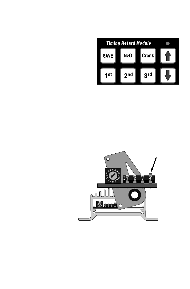
• Open the A
CCEL ignition’s cover plate (the one with the wires coming through it).
Unscrew the three screws and swivel it out of the way to reveal the
• Using a small tool (A pencil is good) gently push up
Switch-4, inside the ACCEL ignition module, must be re-set UP.
DIP-Switches.
DIP-Switch-4.
300+ ignition box has been
CCEL
This A
set to rev-limit an 8-cylinder
engine at 5,000 RPM.
DIP-Switch-4
The owner has installed
an A
CCEL Timing Retard
Module, and has also
set DIP-Switch-4 up.
• After you have set
DIP-Switch-4,
close the cover plate and retighten
all three of its screws.
IMPORTANT POINTS TO REMEMBER
you should remove your ACCEL Timing Retard Module from the car, remember to re-set
IP-Switch-4 inside the ACCEL ignition module DOWN.
• When connected to an ACCEL control module, the ignition module’s DIP- Switch-4 must be UP.
• When not connected to a control module the ignition will not start with DIP-Switch-4 U
P
The rev-limit set inside your ACCEL ignition module is the engine’s ultimate rev-limit.
Make sure that its chosen rev-limit fits your engine’s needs and
the needs of any additional control modules.
Page 4

PRECAUTIONS AND
W
ARNINGS
The ACCEL Timing Retard Module will cause a small, fixed timing retard in the trigger.
This is due to computational delay. Engine ignition timing must be checked, and
re-adjusted, to account for this delay after your timing retard module is installed.
This flexible product makes it easy to select values that can damage your engine.
Start by selecting safe values. Carefully evaluate their effect. Make small changes,
when changing values, and use caution.
MODES OF OPERATION
our new A
CCEL TIMING RETARD MODULE
has three different modes of operation.
1. Programming Programming and Control modes overlap in the sense
2. Control
that timing control is still performed in Programming Mode.
In Programming Mode the display shows the value you are
in the process of programming. In Control mode the LED’s display the
current timing retard from the trigger input.
3. Diagnostics Mode – See Pg. 12.
THE SAVE BUTTON
Pressing the SAVE button tells the Timing Retard Module to store all the values that
have been adjusted. They will be remembered until they have been re-programmed
and over-written with the SAVE button. Turning off the module does not erase any
values that have been stored with the SAVE button.
You can adjust, and test, different settings, without storing values, by turning your
Module off, before pressing SAVE. The unit remembers the last values stored with
he SAVE button, and restores them the next time it is used.
CAUTION: It may take a few seconds for the Timing Retard Module to SAVE values.
Be sure the display shows the current timing retard (default display) before turning
the module off. Powering off during a SAVE may cause you to lose stored values.
After you have completed the wiring (according to diagrams detailed later in this
ocument) you must do some basic configuration of your A
CCEL TimingRetard Module.
Page 5

1. With the unit powered off press, and hold
down, both the SAVE and CRANK buttons.
2. While holding those two buttons down, apply power to the module.
The module will enter its Programming Mode and display a number that
represents the number of cylinders in an engine (the factory default).
3. Use the ⇑and ⇓keys to select the number of cylinders for YOUR engine.
4. When finished, press SAVE. This stores this new information and puts
the module back into Control Mode operation.
Make this selection only once per installation.
If you do not make this selection your
TimingRetard Module uses the factory default.
SETTING S
REASONABLE TIMING R
OME
ETARD VALUES
Enter Programming Mode by pressing the key for the function you wish to modify.
Adjust the timing retard of that function to an appropriate value.
Exit Programming Mode by pressing that same key again.
i.e. To select a timing retard for starting your engine press the
CRANK button.
The display shows its current value and The Programming Dot will start to flash.
Use the ⇑and ⇓keys to adjust (in 1° increments) the value displayed.
When finished press
CRANK again.
The Programming Dot stops flashing and the current timing retard displays.
Do the same for all timing retard inputs. It is not necessary to exit Programming
Mode to select a new function, simply press the next value’s key.
i.e. Press 1
st
and select its value. Then press 2ndand select its value.
nd
Since 2
was the last value you programmed, you
exit Programming Mode by pressing 2
nd
again.
When you have finished programming press SAVE to store all new values.
IMPORTANT PROGRAMMING DETAILS
The initial values you program and save into your Timing Retard Module will get you
started. You will eventually want to modify them. Just select a function and change it.
Modifications take effect immediately. Press that function’s key again (displaying current timing retard), and the newly selected value takes effect.
st
The 1
, 2nd, and 3rdswitches do not represent gears, but rather switches. On a four
speed manual transmission the switches are normally installed on 2
Timing retard is additive. For example: you program 3° of retard for the 1
of retard for the 2
nd
key. The module will provide 3° of retard when switch #1 gets
activated, then adds 4° (7° total) when switch #2 is activated (while switch #1 remains
active). N
2O timing retard, when active, is also additive.
If your shifter and switches are designed so that only one switch can be activated at a
ime, the value programmed for each individual switch is not additive.
nd
, 3rd, and 4thgears.
st
key and 4°
Page 6

When connected to an H-Pattern, manual transmission, your Timing Retard Module’s 1st,
nd
, and 3rdkeys each program how much retard takes effect when one gear is selected.
nstall switches on the shifter that, when closed, signal the module that a gear is engaged.
When the A
CCEL Timing Retard Module receives its signal it adjusts timing retard to
e value you have programmed for that gear.
ypically the 3
rd
key, and its switch, is attached to
p gear. The next two highest gears are
en attached, by switches,
wires from the 4-Pin, Flat
onnector. When using your H-Pattern transmission, the values
rogrammed by the Module’s 1
st
, 2nd, or 3rdkeys take effect when their switches trip.
stall switches so one side is connected to +12volts and the other side is connected to the
iming Retard Module’s harness. Switches should be OPEN when their gear is not engaged
i.e. You have programmed, and stored 9° with the
nd
2
button, ⇓ and ⇑ keys, and the SAVE button.
When you shift into 3
by the
DK GREEN & WHITE wire (Connector Pin-C),
is tripped and ignition timing retards by 9°.
EMEMBER: the 2
R
nd
In this example the 2
button refers to the second switch, NOT 2ndgear!
rd
gear its switch, connected
nd
key, and its switch, is wired to 3rdgear.
W
IRING AND
PROGRAMMING AN
AUTOMATIC
TRANSMISSION (Shifted Manually)
Automatic transmissions and their shifters are programmed, and
wired, like manual H-Pattern systems, except the retard switches
are connected to the shifter in a straight line.
As you shift gears, the values programmed take effect; each gear
with its own programmed value.
i.e. You have programmed and stored
a value of 15° into the module
with the 3
rd
button.
When you shift into Top gear the
D
K BLUE & WHITE wire’s switch
trips
(Pin-D on the connector)
, and
timing retards by 15°.
ou may not want to use all three retard.
switches. Wire a manual switch to an unused
wire, and use it to program a conservative Timing Retard for your drive home.
Page 7

IRING AND PROGRAMMING A LENCO-TYPE SHIFTER
W
here are major differences between the Lenco gearbox and shifter, and an H-Pattern
manually shifted transmission:
• The Lenco box accumulates gear ratios.
Higher gear’s ratios are the total
of the lower gear shifts.
•The Lenco has a stick for each gear.
Before shifting into a high gear, all
lower gears must be engaged.
i.e. To be in
AND the 2
th
4
gear, the 3
nd
gear sticks
rd
must also be thrown.
st
•When you are moving forward 1
is always
engaged. Reverse is triggered off 1st.
Keep these differences in mind when installing, and
programming, your new A
CCEL
Timing Retard Module.
s with an H-Pattern or automatic shifter; wire the three
witches to your top three gear positions so that each
ear’s stick, as it is engaged, closes a switch contact.
When in Top gear all three switches will be closed.
ach stick’s switch should have one contact wired
VDC, and the other contact wired to the Timing
o +12
etard Module’s 4-pin flat connector (see Pg 8).
he Timing Retard Module senses when more than
ne switch is closed, and totals the values you have
rogrammed for all lower gear’s shifts.
.e. Assume you are running a four-
speed Lenco transmission, and
you have programmed your new
CCEL Timing Retard Module so
A
that the 1
st
button’s value is 4°, the 2ndbutton is 5,° and the 3rdbutton is 6°.
Remember: A button’s label refers to its switch, NOT to which gear it is wired.
• Usually you will not be adjusting Timing Retard for First gear.
The ACCEL Timing Retard Module has been designed to adjust
Retard for three forward gears, and for Nitrous
(see Pg-11)
.
• When you shift into 2ndgear you will get 4° of Retard,
since the 1stbutton has been programmed 4° for
nd
gear.
2
• When you shift into 3rdgear you will have 9° of Retard.
The 1stbutton’s 4° is added to the 2ndbutton’s 5°,
making a total of 9° when you are in
rd
3
.
• Shift into 4th(Top) gear and you will get 15° of Retard.
st
1
and 2ndvalues are added to the 3rdbutton’s value;
4° + 5° + 6° totals 15° of Retard, for
th
4
gear.
Page 8

Page 9

Page 10

HE 2-P
IN, INPUT CONNECTOR
(Main Power)
This is the main power input for
CCEL Timing Retard Module.
your A
Its
B
wire is Grounded and
LACK
R
wire inputs +12
its
ED
VDC
from the battery.
(not more than +
or less than +
18 VDC
8 VDC)
In general, the best place
to Ground the
RED wire
The
connects to the battery
through the power or
key switch.
HE SQUARE, INPUT CONNECTOR (Trigger Input)
T
CCEL Timing Retard Module takes all kinds of triggering, except Distributor-less.
he A
is on the engine.
Make sure that rubber
mounted engines are
well Grounded.
BLACK wire
s digital micro-processor controls are as sensitive as your trigger, and we recommend you
CCEL Crank Trigger or Billetech Distributor. The triggering inputs are read either
se an A
hrough the Square, Male connector’s P
he W
HITE
wire typically gets its
URPLE and O
RANGE wires, or the WHITE wire.
quare wave input from:
• All Points ignitions
• Some
HEI modules
• Most Fuel Injections
he P
URPLE and ORANGE wires get
heir inputs from either Magnetic
ickup or Crank-triggered systems.
URPLE wire is the Positive
he P
+)
(
nput and the Orange wire is the
(–). See chart at right.
egative
your system uses the WHITE wire,
ou must isolate and insulate both
URPLE and ORANGE wires.
he P
your system uses both the P
URPLE
nd ORANGE wires, you will isolate
nd insulate the W
he L
IGHT GREEN wire connects
irectly to the Tach’s signal lead.
HITE wire.
* Older ACCEL Crank Triggers may connect
W
HITE
to PURPLE and BLACK to ORANGE
THE 4-PIN, FLAT CONNECTOR (Input from Switches)
his connector receives signals from switches telling the module when to adjust Timing
etard. You do not have to connect all four switches. (See Wiring Diagram on Pg, 8)
Page 11

WIRING
GEAR SHIFT SWITCHES
lthough programming may be different for Automatic, H-Pattern, or Lenco type trans-
missions, the way you place and connect their switches will probably be similar.
nfortunately gear shifts come in many different shapes, and we cannot tell you which
ind of switch you should use. You’ll have to choose and attach your own switch.
SOME GUIDELINES FOR
ATTACHING SWITCHES
A momentary or a toggle switch is
•
probably best: one that stays in its
tripped position until the shifter is
put into another gear.
Place your switch so that only the
•
selected gear shift can trip it.
Make sure all switches are firmly
•
fixed in place, and that nothing can
tangle their wires.
WIRING F
Ground the same way
that you Grounded the
2-Pin Connector.
OR NITROUS
Connect the G
REY wire to the Nitrous
system by splicing it to the wire running
between the Nitrous solenoid and the
Nitrous activation switch.
Timing Retard for Nitrous is added on top of whatever Timing Retard is already active.
i.e. You have programmed Top gear to retard timing by 15° with the
rd
3
button, and Nitrous to retard by an additional 5° with the N2O key.
You are in Top gear when your A
CCEL 3-Stage Rev-limiter activates
the Nitrous system. Total Timing Retard instantly becomes 20°.
With Multi-stage Nitrous use any unused switch to sense when the system is activated.
Wire the unused switch to the negative terminal of any Nitrous solenoid. (See Pg 8.)
T
HE SQUARE, OUTPUT CONNECTOR (Trigger Output)
utputs the triggering signals received, through the 4-Pin Square Input connector, to your
gnition. If you are using an A
CCEL+ ignition, its input connector is already in place.
using a third party’s CD ignition, build a mating connector , with the connector supplied.
The BLACK& WHITE wire connects to the
Points terminal of a CD ignition.
IGHT GREEN & BLACK wire connects
The L
to a CD ignition’s Tach input.
Connect wires according the instructions
that come with your CD ignition system.
Connect the
the White
wire (Pin-C) to the
CD’s Points input.
& BLACK
Connect the
T GREEN & BLACK
L
(Pin-D) to the
CD’s Tach input.
Page 12

LED’s do The Timing Retard Module is not getting power.
not display Check the 2-Pin connectors’s Red and Black wires. See Pg 10.
A timing light The engine was not retimed when the Timing Retard Module was
does not show originally installed, or the wrong number of cylinders was selected
he programmed Time the engine again. See Pg 3.
value Check the number of cylinders (4, 6, or 8). See Pg 5.
Tachometer Any one of the Tachometer wires throughout the system may
does not be disconnected or shorted, or the Tach itself may be broken.
work Check the square, input connector first. See Pg 10.
Your A
CCEL+ DIP-Switch-4 inside your ACCEL+ ignition is down.
sparks randomly See Pg 3.
Status Light on The ignition is not firing, or the Timing Retard Module is unplugged
CCEL+ from the ignition. The battery may be low.
Your A
is Dim If the 2-Pin connector and battery are OK, pull a spark plug, lean it
against the engine. It should spark as you crank the starter. See Pg 10.
Status Light on The unit is not sending a trigger signal, probably because
Your A
+ it is not receiving a trigger signal. Check the trigger device
CCEL
is O
FF and the square, input connector. See Pg 11.
Timing doesn’t The unit does not have a value programmed for that gear, or
hange when car it is not getting a signal from that gear shift.
is in a new gear Check the switch and its wires. See Pg 11.
DIAGNOSTIC MODE
our A
CCEL Timing Retard Module has features that test functions through your key pad.
iagnostic Mode does not perform any Control Mode engine functions.
you enter Diagnostic Mode with the engine running, your engine will stall.
(Read this whole section before entering Diagnostic Mode)
ISPLAY, PROCESSOR, and MEMORY test
Enter Diagnostic Mode by simultaneously pressing and releasing three keys:
1ST, 2ND, and 3
RD
. The display will show 00000.
About every two seconds the display will increment: 11100, 22200, up to 99900.
The ‘degree dot’ will appear with the odd numbered (
EY PAD
test
When
99900 appears the ‘programming dot’will start flashing. From now on you must
33300
, 55500) displays.
press the proper key within eight seconds or the module will return to Control Mode.
Keys must be pressed in order:
DISPLAY PRESS
99900 1
11100 2
22200 3
33300
44400
55500 CRANK
66600 SAVE
77700 N
ST
ND
RD
(UP A
⇑
(DOWN Arrow)
⇓
2O
rrow)
After each key is pressed the display will update.
It starts at
11100 and increments to 77700 as
each key is pressed, in order. If the proper key
is not pressed within eight seconds Diagnostic
Mode ends and returns you to Control Mode.
If you press the correct key and the display does
not update (and the unit exits Diagnostics), the
test has found a key pad failure.
When the last key (
N2O) is pressed and released
the unit returns to Control Mode operation.
Page 13

Q
UICK
REFERENCE
Adjusts how much Retard takes effect when you first start your engine.
Press the C
Cranking Retard only takes effect below 600
Sets how much Timing Retard will take effect when Switch #1 is ON.
Press the 1
The Module senses through the
shifter, is
Sets how much Timing Retard will take effect when Switch #2 is ON.
Press the 2
The Timing Retard Module senses, through the
RANK button and adjust the value with the
RPM. (See Pg 5)
st
button and adjust the value with the ⇓or ⇑buttons.
YELLOW wire when Switch #1, on the
CLOSED, and Retards by the amount designated. (See Pg 6)
nd
button and adjust the value with the ⇓or ⇑buttons.
DARK G
or ⇑buttons.
⇓
REEN & WHITE
wire, if Switch #2, is CLOSED and Retards by the set amount.
Sets how much Timing Retard will be in effect when Switch #3 is ON.
Press the 3rdbutton and adjust the value with the ⇓or ⇑buttons.
The module senses, through the
on the shifter, is
CLOSED and Retards by that designated amount.
DARK BLUE &
WHITE wire, if Switch #3,
Switch #3 is typically attached to the tallest gear.
Sets how much Timing Retard takes effect when Nitrous is activated.
Press the N
2O button and adjust the value with the
Nitrous activation is sensed through the Grey wire
spliced to the Black wire between the N
2O Solenoid activates Nitrous Retard. (See Pgs 8& 11)
The N
NSTALLATION CHECKLIST
I
2O Solenoid and the N2O Switch.
and ⇑keys.
⇓
(4-pin, flat connector),
Disconnect the battery’s negative (ground) connections.
Install the your A
Install and connect the 1
Install and connect the N
CCEL ignition module and set its DIP-Switches. (Pg 3)
st
, 2nd, and 3rdswitches. (Pgs 6-11)
2O input. (Pg 11)
Install the trigger input. (Pg 11)
Connect your A
CCEL Timing Retard Module to your ACCEL ignition module. (Pg 3)
Reconnect the battery.
Program your Timing Retard Module for the proper number of cylinders. (Pg 5)
Program reasonable values for 1
Save these initial values into memory with the
st
, 2nd, 3rd, N2O, and Crank. (Pg 5)
SAVE button. (Pg 5)
Adjust and verify the correct engine timing. (Pg 4)
Fine tune any values that need re-adjustment and save the new values.
Page 14

CCEL
A
DRAG RACE COIL
PART # 140010
ACCEL TIMING RETARD MODULE
COMPATIBILITY CHART
ACCEL SUPER COIL
PART # 140009
CCEL 3-STAGE R
ART
# 49345
EV-LIMITER
ACCEL TIMING RETARD MODULE
PART NUMBER - 49355
Any of the A
ignition systems,
in this case an
CCEL 300+.
A
Your ACCEL
CCEL+
TIMING RET ARD
MODULE connects directly to any
Capacitive Discharge ignition system.
If it is connected through an
A
CCEL 3-STAGE REV-LIMITER,
it outputs to the ignition
through the Rev-limiter.
The A
CCEL TIMING RETARD
MODULE accepts input from
any Accel distributor, Crank
Trigger, Nitrous system,
or fuel injection.
Do not connect with
an A
CCEL TIMING
COMPUTER.
ACCEL CRANK
TRIGGER
B
ILLETECH
DISTRIBUTOR
Fuel Injection
and/or
Nitrous system.
Page 15

ACCEL+ TIMING RETARD MODULE
rag Racers must be able to launch off the line hard, with MAXIMUM TIMING ADVANCE.
eat, caused by combustion, can cause engine damaging “Detonation”. Retarding ignition
ming can prevent detonation. The A
esigned for this purpose. Your new A
gnition timing retard for single or multi-stage Nitrous.
When using the A
CCEL+ TIMING RETARD MODULE you have four possible adjustments for
etarding ignition timing, based on four different specific inputs: three gear switches, and
ne Nitrous switch. These four switches do not have to be wired only to the various gears,
r Nitrous, that their control panel keys suggest. If you wish, you can wire the retard
nputs to whichever switch or device you like. You may even want to rig a manual switch
or specific situations, such as driving to or from the race track.
CCEL+ TIMING RETARD MODULE has been specifically
CCEL+ TIMING RETARD MODULE can also adjust
For installation questions call
216-398-8300 Ext-310
 Loading...