

Page 1
Page 2

Congratulations! You have purchased the ACCEL TIMING COMPUTER.
Your ACCEL TIMING COMPUTER allows you to pre-program timing curves, for engines
at use distributors, from 0 to 16,000
ressure with a MAP sensor it can adjust timing for vacuum advance and boost retard. It also
as inputs for Nitrous R
etard and two RPM-activated outputs.
RPM
in 500 RPM increments. When reading manifold
You must use your A
CCEL TIMING COMPUTER with an ACCEL+ ignition module.
Use ACCEL
RACE WIRE spark plug wires!
300+
Solid-core spark plug wires emit RFI and EMI static,
which can disrupt On-board electronics.
Do not use your TIMING COMPUTER with more than 18 volts.
Do not use your TIMING COMPUTER with another timing control module.
They both may try to override each other.
Your ACCEL TIMING COMPUTER, like any electronic component, is sensitive to heat.
Keep it away from temperatures greater than 150°F (65°C)
.
Follow the installation instructions in this Owners Manual carefully.
Incorrect installation can damage the Timing Computer, damage
your engine, and may
VOID YOUR W ARRANTY.
This unit cannot be returned to your
dealer for testing or for warranty.
It must be returned to:
MR. GASKET PRODUCT REPAIR
8700 BROOKPARK ROAD
CLEVELAND
216-398-8300 Ext-310
, OH 44129
Your warranty card must be on record at
A
CCEL to insure warranty processing.
(See your warranty card for details.)
his package provides everything you will need to install your ACCEL TIMING
COMPUTER. Wire lengths provided are enough for almost all vehicles. If you must splice
dditional wire use 16 gauge wire, or larger.
We
STRONGLY recommend you install an ACCEL
Crank Trigger with your Timing Computer.
With no crank trigger you will need a Locked
Distributor and a Rotor Phasing Kit.
To use the Vacuum Advance and Boost Retard
unctions you must install a 2-Bar MAP Sensor
A
CCEL/DFI Part# 74776). Install it either on
he intake manifold or the carburetor base.
(No need for a 3-Bar MAP Sensor)
ADDITIONAL HARDWARE
Page 3
THE TIMING COMPUTER – AN OVERVIEW
our new ACCEL TIMING COMPUTER controls the signals that tell your ignition when to fire.
must be installed between your triggering device (distributor pickup, crank or magnetic
igger, etc.) and your ignition module.
our A
CCEL TIMING COMPUTER also has two
dditional inputs to further adjust timing
alues (from a MAP Sensor and a Nitrous
olenoid). It outputs timing values to your
CCEL+ ignition. It can also output, through
wo internally switched connectors, to two
PM-activated devices (either a Shift Light,
2O solenoid, or even an Air Shifter).
While the A
CCEL TIMING COMPUTER is not a complicated device, installation requires some
pecific knowledge. You will be better prepared for its initial and future configuration if
ou read this manual before installation and keep some important details in mind.
• Use caution when selecting values. Make small changes and then evaluate their effect.
• The rev-limit set in your A
CCEL+ ignition module is your engine’s maximum rev-limit.
Be sure it fits your engines needs and the needs of any additional control modules.
• Disconnect Nitrous, during installation and configuration.
• The A
CCEL TIMING
COMPUTER causes a small fixed timing retard in the trigger, due
to computational delay. Engine timing
MUST be adjusted during and after installation.
• The Timing Computer has three operating modes: Programming Mode, Control Mode, and
Diagnostics. Programming and Control modes overlap (ignition control is performed
while the Timing Computer is in Programming Mode).
Diagnostics Mode see Pg 17.
• It may take a few seconds for the Timing Computer to store saved values. Be sure
the LED display stabilizes, to show your current engine timing, before turning the
module off. Powering off during a save operation may corrupt the unit’s memory.
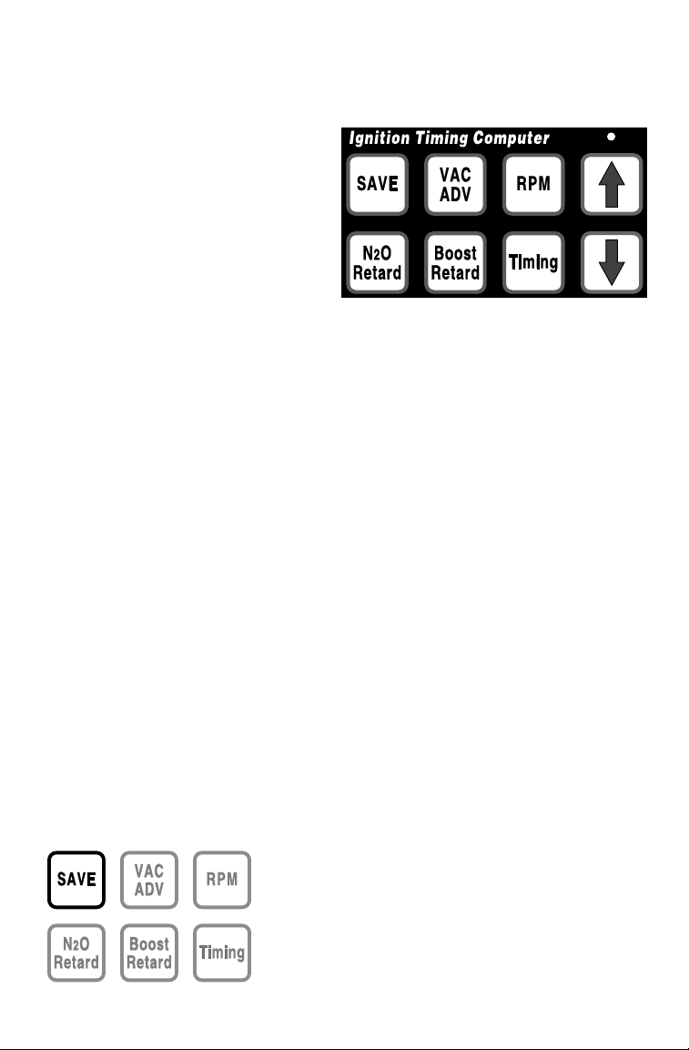
ADJUSTING AND STORING VALUES
The SAVE button tells the A
CCEL TIMING C
OMPUTER to store all newly adjusted values.
They will be remembered, until they have been re-programmed and then over-written with the
SAVE button.
You can adjust, and test, but not store values by turning
your
TIMING COMPUTER off, without pressing SAVE.
LED’s will display the current timing curve, or the
The
RPM of whatever function you are adjusting.
Page 4
CONNECTING THE ACCEL TIMING COMPUTER
ACCEL IGNITION SYSTEM
TO AN
he ACCEL TIMING COMPUTER uses special signals to communicate with your ACCEL+
gnition, and
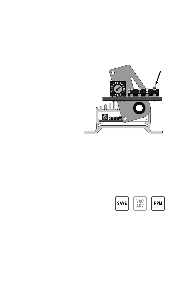
• Open the A
Unscrew the screws and swivel it out of the way to reveal the
• Using a small tool (A pencil is good) gently push up
DIP-Switch-4, inside your ACCEL+ ignition module, must be pushed UP.
CCEL+ ignition’s cover plate (the one with the wires coming through it).
DIP-S
witches.
DIP-Switch-4.
This A
set to rev-limit an
engine at 5,000
When connected to any A
module,
DIP-Switch-4 must be pushed UP.
CCEL
300+ ig
nition box has been
8-cylinder
RPM.
CCEL control
DIP-Switch-4
When not connected to a module push
DIP-Switch-4 DOWN.
When not connected to an A
CCEL
control module your ACCEL+ will
not start with
DIP-S
witch-4 UP.
• After you have set dip-switch-4,
close the cover and retighten all
three of its screws.
you move your A
CCEL TIMING COMPUTER to a different car, or make significant changes
o your engine, you probably will also want to change most, if not all, of its stored values.
may be a good idea to treat any major engine change as a brand new installation, and
eprogram your Timing Computer from the ground up.
eep a good record of what values were used, when, and why! These records will be very
aluable, saving both time and parts, if and when you make more changes.
SELECTING THE NUMBER OF CYLINDERS
1. With the unit powered off press and hold
down both the SAVE and RPM buttons.
2. While holding both buttons down, apply power to the Timing Computer.
It will display a number that represents the number of cylinders in an
engine (
the factory default is 8).
3. Use the ⇑and ⇓keys to select the number of cylinders for your engine.
4. When finished, press SAVE. This stores this new information and puts
the module back into Control Mode operation.
If you do not make this selection your
Timing Computer uses the factory default.
Make this selection only once per installation.
Page 5

PROGRAMMING YOUR TRIGGER POSITION (Maximum Timing - 34°)
good choice to program for trigger position is the maximum timing you’ll ever use plus 2°.
1. With the engine stopped, and the Timing
Computer powered off, adjust the trigger
(distributor position, crank or mag trigger, etc.)
Programming
Dot
as close to 36° as possible.
2. Press and hold the SAVE and VAC ADV buttons,
and apply power. The unit will display a value for
Trigger Position.
3. Use the ⇑or ⇓key to select 36° (For the example
we are using), and press SAVE to store this new
value and also return to Control Mode.
CONFIGURING MAXIMUM TIMING WITH A CRANK TRIGGER
et your ‘Rotor Phase’to 20° BTDC (most timing curves center around this arbitrary point).
1. Rotate the engine until Cylinder-1 is at 20°
BTDC.
2. Adjust the distributor so the rotor centers on Cylinder-1’s terminal.
The A
CCEL TIMING COMPUTER has a Computational Delay of 2°.
New Timing Computers come with a default trigger
configuration of 36°, for a “Maximum Timing” of 34°.
(Trigger minus 2° Computational Delay = Maximum Timing)
3. To use the factory default, adjust your crank trigger to 36°.
(36°Crank Trigger minus 2° Computational Delay = 34°Maximum Timing)
CONFIGURING MAXIMUM TIMING WITHOUT A CRANK TRIGGER
Instead of a crank trigger use a locked distributor and
a rotor phasing kit, or an A
et your ‘Rotor Phase’ to 20°
1. Rotate the engine until Cylinder-1 is at 20° BTDC.
2. Adjust the rotor (NOT the distributor body) to center on Cylinder-1’s terminal.
3. Adjust your distributor body to match the Timing Computer’s
BTDC (most timing curves center around this arbitrary point).
CCEL BILLETECH distributor.
trigger position (i.e. 36°).
CONFIGURING A HIGHER MAXIMUM TIMING (for example 50°)
1. With the power off, adjust your trigger to 52°.
(52° Trigger minus 2° Computational Delay = 50° Maximum Timing)
2. With the power still off, hold down the VAC ADV and SAVE buttons, and
power-up the unit (Do not start your engine yet).
The LED display will show the current trigger configuration.
3. Push the ⇑button until the display reads 52°
This tells the Timing Computer that the crank trigger is at 52°.
The actual Maximum Timing is 50° (52° minus Computational Delay).
4. Store this new value of 52° by pushing the SAVE button.
5. You can now power-off the unit or continue with further programming,
Page 6
SETTING TIMING – ABASE CURVE
he ACCEL TIMING COMPUTER has been designed to automatically Advance or Retard your
gnition timing to meet changing conditions. You must program a Base Timing Curve
efore it can make any adjustments. The Base T iming Curve is the timing that takes effect
t specific RPM and atmospheric pressure
he Base Curve, and all future adjustments, are done in 1° per 500
1. Begin by pressing the
the
LED display reads the desired RPM value (start at 00000).
2. Press the
TIMING button and, also with the
RPM button. Use the
(no Vacuum, no Boost, no N20, open throttle).
RPM increments.
and ⇓buttons until
⇑
and ⇓buttons,
⇑
modify the value displayed to your pre-determined value.
3. Repeat Step
500
4. When you are satisfied with the values entered press the
-1 and Step-2, increasing the RPM value displayed by
rpm, and modify timing until you reach your Peak RPM.
(Do
NOT skip any of the 500 RPM increments!)
SAVE button,
storing all values currently in effect.
N ALTERNATE METHOD OF REV
A
go another 500
RPM increment and retard timing by 10°–15°.
-LIMITING
– When you reach Peak RPM.
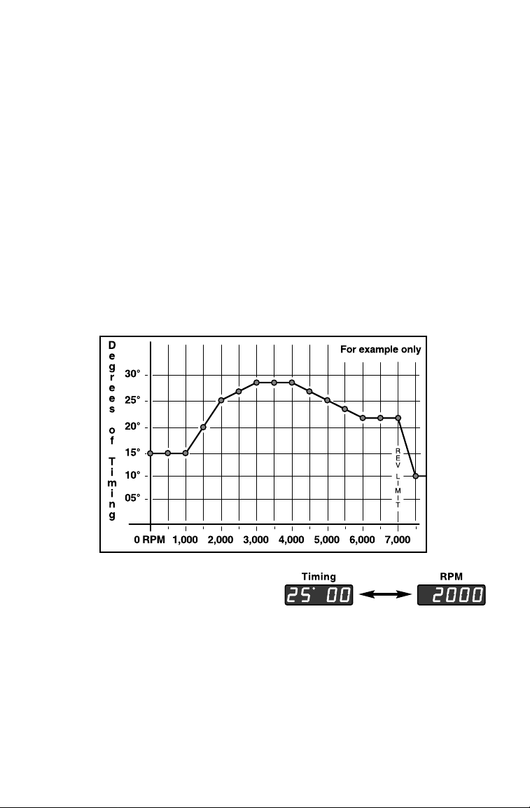
The Timing Computer’s display at 2,000
when you toggle between T
IMING and RPM,
RPM,
or the chart, and timing curve shown above.
f the timing programmed for 1,000
Timing Computer will compute the correct timing for
RPM
is 15°, and the timing for 1,500
1,100, 1,200, 1,300, and 1,400RPM.
RPM is 20°, the
Timing will ramp up slowly from 15° to 20°. There will not be a sudden jump of 5°.
The maximum ignition advance and the trigger position are interdependent. Your A
CCEL
TIMING COMPUTER will not allow a maximum advance beyond trigger position minus 2°.
You cannot set a trigger position less than the timing curve’ s maximum advance plus2°.
Therefore - during installation some of the Timing Computer’s factory defaults may
ave to be modified to smaller values, before you can set the trigger position.
Page 7

SETTING VACUUM ADVANCE / BOOST RETARD
The A
CCEL Timing Computer can program Vacuum and Boost when Manifold Absolute
ressure is read with a 2-Bar MAP Sensor. When Vacuum Advance or Boost Retard takes
ffect, the whole Base Timing Curve either Advances or Retards.
(MAP Sensor info Pg 4)
When Retarding timing, the number displayed is subtracted from the Base Timing Curve.
When Advancing timing, the number displayed is added to the Base Timing Curve.
(Timing, however, can never exceed Maximum Timing.)
Decide how much timing to add for maximum vacuum, and how much to subtract for
maximum boost. Program both values into the Timing Computer by pressing
or
BOOST
RETARD
I.E. If you want 5° extra Advance for maximum vacuum (throttle closed) - press the
VAC ADV button, adjust the display to read 5°, then press the SAVE button.
Assume the Base Curve’s timing is set to 25° at 5,000 RPM - taking your foot
off the
As always; press the
buttons, and adjusting the number displayed with the ⇑or ⇓buttons.
throttle at that speed ramps timing up to 25° + 5° = 30°.
SAVE button and wait for the display to stabilize to store new values.
V AC ADV,
RPM-ACTIVATED SWITCHES
here are two RPM-Activated switches: one with RED &WHITE and BLACK&PINK wires, and
ne with
he other wire is switched to ground inside the Timing Computer. Connect any
BROWN and PINK wires. In each connector, one wire provides battery power and
RPM-
ctivated device (Shift Light, Air Shifter, N2O Actuator) to either one.
Setting the BROWN
and PINK Connector
1. Press RPM and BOOST RETARD
at the same time.
2. Adjust the value displayed with the
and ⇓buttons.
⇑
3. Store new value with the SAVE button.
Setting the RED & WHITE
and BLACK & PINK Connector
1. Press RPM and N2O RETARD
at the same time.
2. Adjust the value displayed with the
and ⇓buttons.
⇑
3. Store new value with the SAVE button.
Page 8

CONFIGURING WITHOUT A MAP SENSOR
lthough we do recommend a MAP Sensor, you can operate without one. For best results
se Magnetic Triggering, or a Points Distributor with mechanical advance locked out.
o not adjust or remove the Vacuum Advance mechanism on the distributor.
1. Program your Base Timing Curve as described on Pg 6.
2. Set VAC ADV and B
OOST RETARD both to 0°.
3. Press SAVE to store all new values.
ADJUSTING YOUR IGNITION TIMING TO PROPER SPECIFICATIONS
1. Start your engine and then press the TIMING and VAC ADV keys.
The Timing Computer displays the number of degrees BTDC ignition timing.
2. Use the
and ⇓keys to select one of the engine timing marks as a value.
⇑
Your Timing Computer will use this fixed ignition timing, regardless of
engine speed or other inputs.
3. Make fine adjustments to your trigger input, with a Timing Light,
so it matches the value on the Timing Computer’s display.
4. Return the display to Control Mode by pressing the TIMING button twice.
REV-LIMITING WITH THE
TIMING COMPUTER
our ACCEL+ ignition has the final say in rev-limiting, but there are ways you can use
he Timing Computer to rev-limit at a lower engine speed than what has been set in the
gnition box. One way is to retard timing by 10° – 15° at your chosen engine speed, as
hown on Page 7. Another way is program a rev-limit with the Accel Timing Computer.
1. Press the RPM and VACADV keys to get into Programming Mode.
The current value for rev-limit will display.
2. Use the
(
Note: Your ACCEL+ ignition rev-limits in 250 RPM increments.)
3. Press the RPM button twice, to return to Control Mode, and then press SAVE.
and ⇓keys to adjust this value in 100 RPM increments.
⇑
USING THE DISPLAY AS A DIGITAL TACHOMETER
ou can make your Timing Computer display engine RPM by simultaneously pressing
oth the
RPM and TIMING keys. It will continue displaying as a digital tachometer until
ou enter Programming Mode. When you exit from Programming Mode the LED’s will
nce again display engine timing.
RESTORING THE FACTORY DEFAULT SETTING
ou may decide, for one reason or another (such as replacing a major engine component)
o restore the Timing Computer’s original Factory Defaults. To restore Factory Defaults:
1. Turn the power OFF.
2. Press and hold down SAVE and BOOST RETARD and apply the power.
When the display reads 12300 release both keys.
FACTORY SETTINGS: a default timing curve, no adjustment for additional inputs,
RPM Activated Switch-1 set at 4,500
RPM, Switch-2 set at 6,500 RPM,
no rev-limit, Cylinders = 8, Trigger Position set to 36° BTDC.
Page 9

ACTUATING N2O
Brown and
Pink wires
nstall all your N2O hardware according to the manufacturer’s instructions. If you are
sing an A
CCEL
3-STAGE REV -LIMITER to trigger N2O, follow the Rev-limiter’s instructions.
using a third party’s actuator, follow that manufacturer’s instructions.
our new A
CCEL TIMING COMPUTER
as two RPM-Activated switches connected to two 2-pin connectors.
Use one of them to actuate N
or consistency use the connector
ROWN and PINK wires.)
ith the B
2O.
ssemble it by splicing the N2O
olenoid’s Red (+) wire
o the Pink wire, and its Black wire to the Brown wire.
he N
2O solenoid is actuated through one of five possible connections: one of the two
-pin connectors coming from the Timing Computer,
oming from an A
CCEL 3-STAGE
REV-LIMITER
OR a third party actuator.
,
OR one of two 2-pin connectors
Both 2-pin, female output connectors are switched to Ground inside
he Timing Computer, and both connectors supply enough power to
rive multiple solenoids. Two solenoids, wired
n parallel, is common but different solenoids
may have different energy requirements.
he
ACCEL TIMING COMPUTER can drive up to three HURST solenoids (Roll Control solenoid
alve – Part# H566 7550) wired, in parallel, to either of these two 2-pin outputs.
N
2O makes more oxygen available for combustion and the air/fuel mixture burns very fast.
s a result, the mixture should be richened and the ignition timing Retarded.
PROGRAMMING NITROUS ACTUATION
he connector with the Red& White and Black & Pink wires is programmed by the RPM
nd N2
O RETARD
buttons. These buttons and this connector do not effect N
1. Decide at what
2. Press RPM and N2
3. Adjust the value with the
RPM you want N2
O RETARD
to display its current value.
and ⇓buttons.
⇑
O to be activated.
2
O retard.
4. Press SAVE to store the new value.
PROGRAMMING
NITROUS R
ETARD
(Through the Flat, 4-Pin Connector – See Pg 10)
o matter how N2O is triggered, the Timing Computer reads when it has been actuated
hrough its flat, 4-pin connector. The buttons and connectors do not affect N
When the N
2O solenoid is actuated the entire value set for N2O Retard is immediately
2O actuation.
ubtracted from the timing curve.
1. Decide exactly how much Retard you want.
2. Press the N2O RETARD button to display its current value.
3. Adjust with the
and ⇓buttons.
⇑
4. Press SAVE to store your adjustments.
Page 10

THE 4-PIN, FLAT, INPUT CONNECTOR
he 4-pin, flat connector is your ACCEL TIMING COMPUTER’s main power input.
It also inputs signals from the N
2O actuator
for Nitrous timing retard.
RED Connects to +12 volts.
B
LACK Connects to Ground.
G
RAY Connects to the Black ground
wire from the N
Y
ELLOW Connects to the Red +12 volt
power wire from the N
2O actuator.
2O actuator.
TWO RPM-ACTIVATED 2-PIN OUTPUT CONNECTORS
ince both connectors are powered and switched to ground inside the Timing Computer,
ither connector can be used for any
witch or power source. The RPM-1 Pink wire and the RPM-2 Red
ontinuos battery voltage. Both
RPM-Activated device. Neither needs an external
&White wire supply
RPM-Activated switches can drive multiple solenoids.
Please, be sure to wire the correct connectors to their correct solenoids and devices!!
THE SQUARE, FEMALE OUTPUT CONNECTOR
he square, female plug is the TIMING COMPUTER’s
main output connector.
Connect it to an A
CCEL+ ignition, OR
Connect it through your ACCEL 3-STAGE
REV-
LIMITER to an ACCEL
+ ignition.
In either case the square, male (input)
connector should already be in place.
If it has not yet been wired,
see the A
Remember: when using an A
miter, you must use an A
CCEL+ Ignition’s manual.
CCEL 3-Stage Rev-
CCEL+ ignition system,
with DIP-Switch-4 pushed up).
using your A
CCEL TIMING COMPUTER with any
xternal rev-limiter, the rev-limiter is placed
etween the Timing Computer and the A
CCEL+.
To an A
CCEL 3-STAGE
REV-LIMITER
The Square, output
connector plugs into
+ ignition or
CCEL
an A
CCEL 3-STAGE
an A
REV-LIMITER.
To an ACCEL+
Ignition
Page 11

THE SQUARE, 4-PIN, MALE INPUT CONNECTOR
he ACCEL TIMING
COMPUTER
inputs from all kinds of trigger types, except distributor-less,
nd its digital, micro-processor controlled, rev-limiter will be as sensitive as your trigger.
We recommend an
re read through the square male connector:
Your ACCEL+ ignition system should already have this connector in place.
he W
HITE wire’ s input is in the form of
Square Wave. It gets this input from
ACCEL Billetech Distributor or ACCEL Crank Trigger. Triggering inputs
WHITE
wire, or the PURPLE and ORANGE wires.
:
• All points ignitions
• Most fuel injections
HEI modules
• Some
PURPLE and ORANGE wires get their
he
nputs from magnetic pickup or crank-
iggered systems
PURPLE wire is a positive (+) input
he
ORANGE is a negative (–) input.
nd the
(See chart for various connections.)
your system uses the WHITE wire you
ust isolate and insulate the
PURPLE
nd ORANGE wires. If your system uses
PURPLE and ORANGE wires you must
he
olate and insulate the
CCEL Crank triggers may connect WHITE to PURPLE and BLACK to ORANGE.
Older A
*
WHITE wire.
THE MAP (MANIFOLD ABSOLUTE /AIR PRESSURE) SENSOR CONNECTOR
he MAP Sensor’s signal to the Timing Computer is through the flat, 3-pin connector.
BAR
nstall a 2-
MAP Sensor, according to its own instructions and plug the Timing
Computer’s male connector into the sensor’s 3-pin female port.
he MAP Sensor reads intake manifold pressure. This makes it possible for the Timing
Computer to adjust to a predetermined timing curve under Vacuum or Boost conditions.
Use an A
(No need for a 3-Bar MAP Sensor, even with high boost.)
CCEL / DFI 2-BAR MAP Sensor, Part# 74776
he MAP Sensor measures pressure. Manifold Absolute Pressure is near 0 BAR at high
acuum, near 1
BAR at wide open throttle, and up to 2 BAR at about 14 PSI of Boost.
Vacuum sensing provides a linear advance of the Base Timing Curve from 0° to full
dvance during high vacuum conditions.
I.E. You have set Maximum vacuum advance
t 10°. At wide open throttle there is little intake manifold vacuum and ignition timing
ollows the
dds 5° (
RPM curve. At light load (.5 BAR, about 15 inches of Hg) the Timing Computer
half the 10° Maximum Timing) to the Base Timing Curve.
Boost retard works the same but in the opposite direction: Suppose you program a Boost
Retard value of 6° at the maximum sensing boost of 1
about 7 PSI) boost the Timing Computer retards ignition 3° from the Base Timing Curve.
BAR (about 14 PSI). At 0.5 BAR
Page 12

Page 13

Page 14

QUICK REFERENCE
When setting Timing this button will show a value for RPM.
This button is also used, with other buttons, for other functions.
Shows Timing at a selected RPM.
It is also used with other buttons for other functions.
These buttons
increase or decrease
the displayed values.
Adjusts the entire Timing Curve up, for Vacuum Advance, in 1° increments.
Can only be used with an A
Adjusts your entire Timing Curve down, for Boost Retard, in 1° increments.
Can only be used with a MAP Sensor.
CCEL 2-Bar MAP Sensor (Part# 74776).
Adjusts the entire Timing Curve down, for N
Do not confuse Programming N
2O Retard with Actuating a N2O solenoid.
2O Retard, in 1° increments.
Toggles the display between a digital tachometer and ignition timing.
Fixes ignition timing, regardless of engine speed or other inputs. Use
arrow keys to modify. This mode is used to set ignition timing with a
timing light and by moving the trigger point to match that value.
Sets the Maximum RPM rev-limit. Use the arrow keys to set this
value in 100 RPM increments. Cannot exceed the rev-limit set by
your A
CCEL+ ignition box.
Controls output to RPM-Activated Switches.
These buttons control RPM Switch-1. If actuating a N
2O solenoid,
use the connector controlled by these two buttons.
The other RPM-Activated function.
These buttons control Switch-2.
When the
SAVE button is pushed, alone or with another button, all current
values are stored. You can adjust values and not store them by turning off the
ignition before pushing
SAVE. Previously stored values will be remembered.
Page 15

TROUBLE SHOOTING THE ACCEL TIMING COMPUTER
LED’s do The Timing Computer is not getting power.
not display Check the 4-Pin connectors’s Red and Black wires. See Pg 10.
Timing light does The engine was not retimed when the Timing Computer was
not show the originally installed, or the wrong number of cylinders was selected
programmed value Re-time the engine. Check the number of cylinders (4, 6, or 8).
(Incorrect cylinder selection can also cause incorrect tach readings.)
LED’s The Timing Computer is not getting a trigger.
Display Check the square input (male) connector,and check all its wires.
0 RPM timing See wiring diagram on Pg 12, and the Triggering chart on Pg 11.
Your A
CCEL+ DIP-Switch-4 inside your ACCEL+ ignition is down.
sparks randomly See Pg 4.
Status Light on The ignition is not firing, or the Timing Computer has unplugged
Your A
CCEL+ from the ignition. The battery may be low.
is Dim If the connectors and battery are OK, pull a spark plug, lean it
against the engine. It should spark as you crank the starter. See Pg 12.
Status Light on The unit is not sending a trigger signal, probably because
Your A
CCEL+ it is not receiving a trigger signal. Check the trigger device
is O
FF and the square, input connector. See Pg 10.
DIAGNOSTIC MODE
our ACCEL TIMING COMPUTER has features that test functions through your key pad.
iagnostic Mode does not perform any Control Mode engine functions, and if you enter
iagnostic Mode with the engine running, your engine will stall.
(Read this whole section before entering Diagnostic Mode)
ISPLAY, PROCESSOR, and MEMORY test
Enter Diagnostic Mode by simultaneously pressing and releasing three keys:
N2O RETARD, BOOST RETARD, and TIMING. The display will show 00000.
About every two seconds the display will increment: 11100, 22200, up to 99900.
The ‘degree dot’ will appear with the odd numbered (
EY PAD test
When
99900
appears the ‘programming dot’will start flashing. From now on you must
33300, 55500) displays.
press the proper key within eight seconds or the module will return to Control Mode.
Keys must be pressed in order:
DISPLAY PRESS
99900 N2O RETARD
11100 BOOST
22200 TIMING
33300
44400
55500 RPM
66600 SAVE
77700 VAC ADV
RETARD
(DOWN Arrow)
⇓
(UP A
⇑
rrow)
After each key is pressed the display will update.
It starts at
11100 and increments to 77700 as
each key is pressed, in order. If the proper key
is not pressed within eight seconds Diagnostic
Mode ends and returns you to Control Mode.
If you press the correct key and the display does
not update (and the unit exits Diagnostics), the
test has found a key pad failure.
When the last key (
VAC ADV) is released the unit
returns to Control Mode operation.
Page 16

INSTALLATION
C
HECKLIST
Disconnect the battery’s negative (ground) connections.
If Nitrous has been installed, disconnect the Nitrous solenoid. (Pg 9)
Install the your A
Connect to the MAP sensor, and N
Connect your A
CCEL ignition module and set its DIP-Switches. (Pg 4)
2O Retard, Shift Light, Trigger Input.
CCEL Timing Computer to your ACCEL+ ignition module.
Reconnect the battery.
Set and save the number of Cylinders in the Timing Computer. (Pg 4)
Program and Save the Trigger Position. (Pg 5)
Decide on a Base Timing Curve and enter all the values. Save them. (Pg 6)
Program and save reasonable values for the N
2O and Shift Light.
Decide on a rev-limit for the Timing Computer. Set and save it. (Pg 8)
If any values are not yet saved, press SAVE now.
Start the engine, adjust, and verify engine timing.
Verify N
2O activation with the Shift Light, then connect the N2O solenoid.
INSTALLATION NOTES
Date Installed: Serial Number: ACCEL+ Rev-limit: Cylinders:
Other Engine Control Modules?
Trigger Position:
Base Timing Curve (enter all values to maximum RPM):
Vacuum Advance: Boost Retard:
Nitrous actuation: Nitrous retard:
RPM-Activated Switch #1: RPM-Activated Switch #2:
gnition Timing: Timing Computer Rev-limit:
Other:
Page 17

A
CCEL
DRAG RACE COIL
PART # 140010
ACCEL TIMING COMPUTER
COMPATIBILITY CHART
Any of the ACCEL+ family
of ignition systems, in
this case an
CCEL 300+.
A
ACCEL SUPER COIL
PART # 140009
ACCEL
3-STAGE
REV-LIMITER PART # 49345
ILLETECH
B
DISTRIBUTOR
Your ACCEL TIMING COMPUTER
connects directly to any of the ACCEL
Capacitive Discharge ignition systems.
If it is connected through an
A
CCEL 3-STAGE
REV
-LIMITER,
and it outputs to the ignition
through the Rev-limiter.
The A
CCEL TIMING COM
PUTER accepts input from
any Accel distributor, Crank
Trigger, Nitrous system, or
A
CCEL DFI system.
Do not connect with an
A
CCEL
TIMING R
ETARD
MODULE.
ACCEL CRANK
TRIGGER
-
 Loading...