

Page 1
T
ECHNICAL INFORMATION
PRODUCT
P 1/ 8
Model No.
Description
UB1102, UB1103
Blower
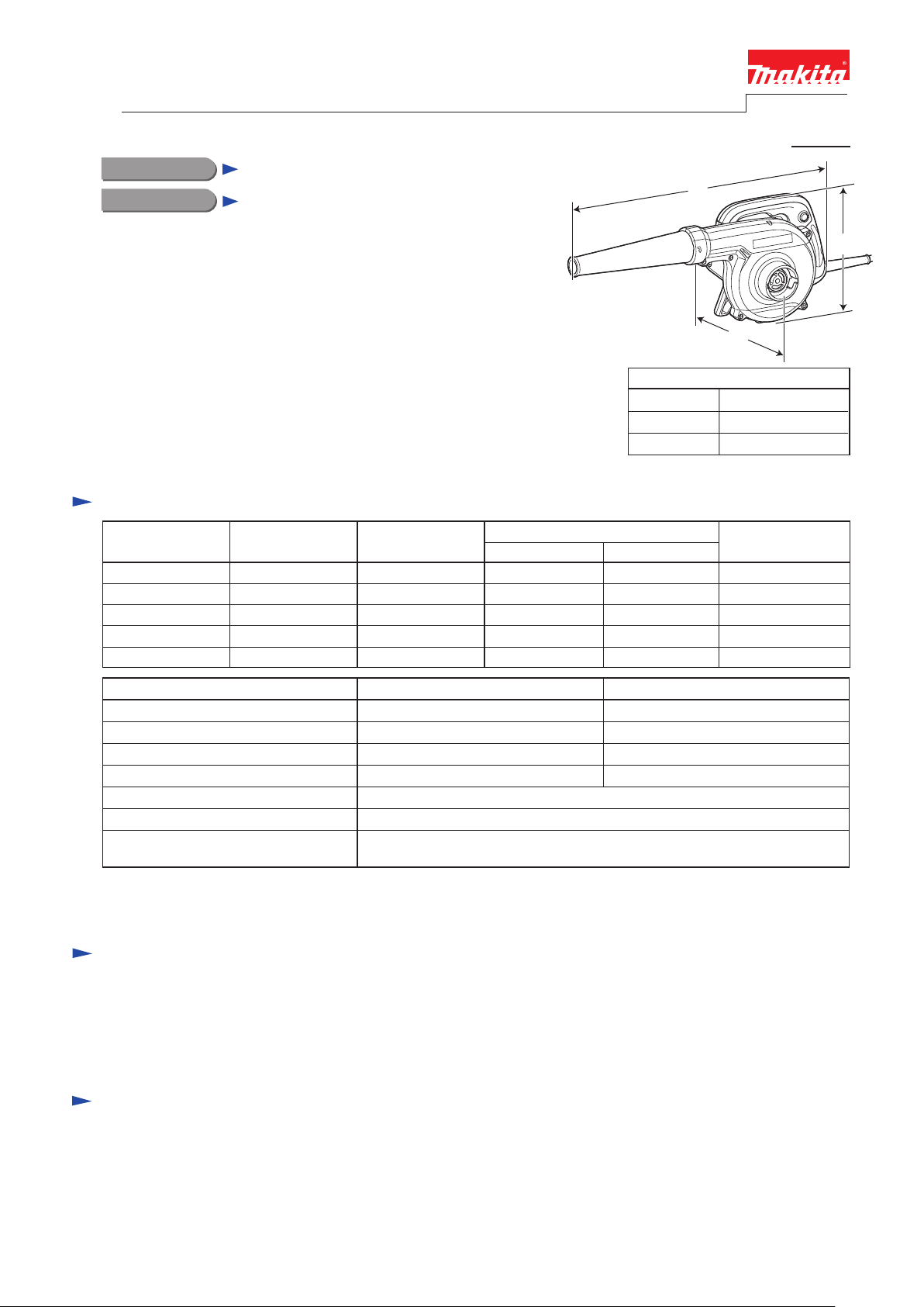
CONCEPT AND MAIN APPLICATIONS
Models UB1102, UB1103 Blowers are successors of UB1100, UB1101.
Their output air volume is 4.1m³/min. over the predecessors 2.8m³/min.
The other features are as follows:
• Ergonomic designed handle with elastomer for more comfortable
and controlled operation
• Self-standing design enables stationary use, easy storage and upside-down
standing
The specification difference between UB1102 and UB1103 is;
UB1102: Single speed
UB1103: Variable speed control by dial and trigger
Specification
Voltage (V) Cycle (Hz)
110
220
230
240
Current (A)
5.7
2.9
2.8
2.7
50/60
50/60
50/60
50/60
Length (L)
Width (W)
Height (H)
Continuous Rating (W)
Input Output
600
600
--- ---
--- ---120 6.8 50/60 ---
--- ---
--- ---600
--- ---600
L
H
W
Dimensions: mm (")
479 (18-7/8)
185 (7-1/4)
178 (7)
Max. Output (W)
Model No. UB1102
No load speed: min.
Max. air volume*
Max. sealed suction: kPa
Variable speed control
Protection against electric shock
Power supply cord: m (ft)
Weight according to
EPTA-Procedure 01/2003*2: kg (lbs)
*1 Without Nozzle, Joint
*2 With Nozzle, Joint
ˉ¹=rpm
1: m³/min.
16,000
4.1
5.7
No
Double insulation
Australia: 0.5 (1.64), Others: 2.5 (8.2)
Standard equipment
Nozzle .....................................1
Joint .........................................1
Dust bag (capacity of 2L) .......1 (for some countries)
Note: The standard equipment for the tool shown above may vary by country.
Optional accessories
Dust bag assembly
Nozzle assembly
Long nozzle assembly
Flexible hose set
Anchor nozzle set (for vacuum function only)
Bending long nozzle set
UB1103
0 - 16,000
0 - 4.1
0 - 5.7
Yes
2.0 (4.3)
Page 2

P 2/ 8
Repair
CAUTION: Repair the machine in accordance with “Instruction manual” or “Safety instructions”.
[1] NECESSARY REPAIRING TOOLS
Code No. Description Use for
1R370 connecting Ring terminals to Brush holderRing Terminal Setting Jig
1R063 assembling Field to Motor housing completeGuide Bar for fitting Field
[2] LUBRICATION
It is not required to lubricate, because the product has no gear mechanism to be lubricated.
[3] DISASSEMBLY/ASSEMBLY
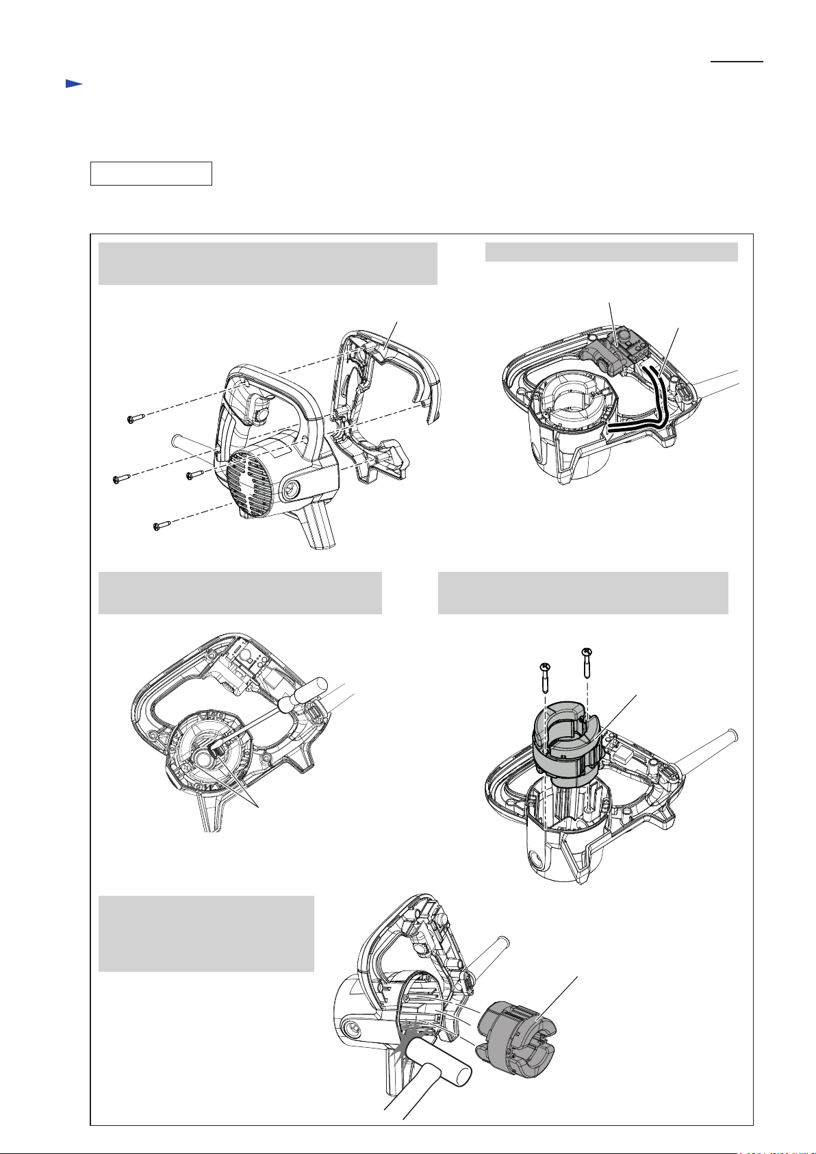
[3] -1. Switch
DISASSEMBLING
1. Switch can be disassembled without separating Fan housing complete section. See Fig. 1.
Fig. 1
1. Remove four 4x18 Tapping screws
that secure Handle cover to Motor
housing.
Handle cover
4. Remove Switch from Handle section
of Motor housing complete.
Switch
2. Separate Handle cover, pulling toward Fan housing complete side
(pulling toward the direction designated with arrow No.1.)
3. Disassemble Handle cover by broadening Handle cover (pulling
its ends toward the direction designated with arrow No. 2).
Now, Handle cover is removed.
Handle cover
Fan housing
complete
No.1
No.2
ASSEMBLING
Assemble Switch by reversing the disassembly procedure. Refer to Fig. 1.
Note: When mounting Handle cover, be careful of the following.
• Switch and Lead wire are not pinched with Handle cover.
Refer to Fig. D-2 and Fig. D-3.
• There are no gaps between Handle cover and Fan housing complete.
Page 3

Repair
[3] DISASSEMBLY/ASSEMBLY
[3] -2. Fan Section
DISASSEMBLING
Disassemble Fan 110 as drawn in Fig. 2.
Fig. 2
P 3/ 8
1. Remove Nozzle.
3. Unscrew five 4x18 Tapping screws
and remove Fan cover.
Fan cover
Nozzle
2. Remove Set plate by prying it off with
a small slotted screwdriver.
Set plate
Fan cover
4. Remove M5-8 Hex nut by turning it
counterclockwise with an impact driver while
holding Fan 110 firmly with a gloved hand.
5. Remove Flat washer 5, Fan 110 and Flat washer 8.
M5-8 Hex nut
Fan 110
Flat washer 5
Flat washer 8
ASSEMBLING
Assemble Fan Section by reversing the disassembly procedure. Refer to Fig. 2.
Note: Align the hole on Set plate with the protrusion on Fan cover, and insert Set plate by hand, then push it
with a small screwdriver until it stops.
Refer to the drawing on the top right in Fig. 2.
Page 4

Repair
[3] DISASSEMBLY/ASSEMBLY
[3] -3. Motor Section
DISASSEMBLING
(1) Remove Carbon brush as drawn in Fig. 3.
Fig. 3
Carbon brush
(2) Disassemble Fan section as drawn in Fig. 2.
(3) Disassemble Armature as drawn in Fig. 4.
P 4/ 8
Fig. 4
1. Unscrew four 4x35 Tapping
screws and disassemble Fan
housing complete.
Fan housing
complete
2. Remove Flat washer 8 from
Armature shaft.
Flat washer 8
3. Remove Armature from
Motor housing.
Armature
Page 5
Repair
[3] DISASSEMBLY/ASSEMBLY
[3] -3. Motor Section (cont.)
DISASSEMBLING
(4) Disassemble Field as drawn in Fig. 5.
Fig. 5
P 5/ 8
1. Unscrew four 4x18 Tapping screws and remove Handle
cover.
Handle cover
3. Disconnect Ring terminals from Brush holders
with a Slotted screwdriver.
2. Disconnect Field lead wires from Switch.
Switch
Field lead wire
4. Unscrew two 5x40 Tapping screws and remove
Field from Motor housing.
Ring terminal
Note:
Tapping the edge of Motor housing
with a plastic hammer enables Field
to be removed easily.
Field
Field
Page 6

Repair
[3] DISASSEMBLY/ASSEMBLY
[3] -3. Motor Section (cont.)
ASSEMBLING
(1) Assemble Field to Motor housing. Refer to the drawing on the middle right in Fig. 5.
Also see Fig. D-2 about the wiring of Field lead wires.
Note: Using 1R063 enables Field to be assembled easily than by hand. See Fig. 6.
Fig. 6
Field
P 6/ 8
1R063
Fig. 7
(2) Connect Ring terminal to Brush holder using 1R370. See
Fig. 7
1R370
Ring terminal
(3) Connect field lead wires to Switch and mount Handle cover to Motor housing with four 4x18 Tapping screws.
Refer to the drawings on the top left and right in Fig. 5.
(4) Insert Armature into Motor housing. Refer to the drawing on the right in Fig. 4.
(5) Mount Flat washer 8 to the drive end of Armature's shaft. Refer to the drawing on the center in Fig. 4.
(6) Assemble Fan housing complete with four 4x35 Tapping screws. Refer to the drawing on the left in Fig. 4.
(7) Assemble Fan 110 and Fan cover. Refer to Fig. 2.
And then, set Carbon brush. Refer to Fig. 3.
.
Page 7

Circuit diagram
Fig. D-1
Lead wire (white or blue) of Power supply
cord connected to P2 terminal
Lead wire (black or brown) of Power supply
cord connected to P1 terminal
Note: Noise suppressor and Line filter are not
used for some countries.
Color index of lead wires' sheath
Black Blue
White
Brown
P 7/ 8
Switch
viewed from Commutator side
Brush
holder A
Field
Brush
holder B
Wiring diagram
Fig. D-2
Wiring of Field lead wires
1. Mount Filed to Motor housing complete as shown below.
Field
connected to
Switch
Line filter
Noise
suppressor
Power supply cord
2. Route Field lead wires through the slit
and Lead wire holder as shown below.
connected to
Switch
Motor housing
complete
Slit
Lead wire
holder
Field lead wires
Page 8

Wiring diagram
Fig. D-3
P 8/ 8
Switch
Motor housing
complete
Field
See the drawing
on the right in Fig. D-2.
1. Pass Field lead wires through Line filter
and wind them one turn and pass them
again as shown below.
Noise suppressor
(if used)
Lead wire
holder
Power supply
cord
Line filter (if used)
Set Line filter with Field lead wires
between Lead wire holders.
2. Winded Filed lead wires have to be located on
the Motor housing complete side.
Field lead wires
Line filter
Motor housing complete
Winded Field
lead wires
Field side
Handle cover
 Loading...