

Page 1
GB High Speed Drill Instruction Manual
M6500
M6501
F Perceuse à Haute Vitesse Manuel d’Instructions
Hochgeschwindigkeits-
D
Bohrmaschine
I Trapano ad alta velocità Istruzioni d’Uso
NL Hoge-snelheid boormachine Gebruiksaanwijzing
E Taladro de Alta Velocidad Manual de Instrucciones
P Furadeira de Alta Velocidade Manual de Instruções
DK Hurtigløbende boremaskine Brugsanvisning
GR Τρυπάνι υψηλής ταχύτητας Οδηγίες χρήσεως
TR Yüksek Hızlı Matkap Kullanma kılavuzu
Betriebsanleitung
Page 2
12
A
B
3
1
2
013476 013477
5
4
7
6
34
5
013475 013712
015473
2
Page 3
ENGLISH (Original instructions)
Explanation of general view
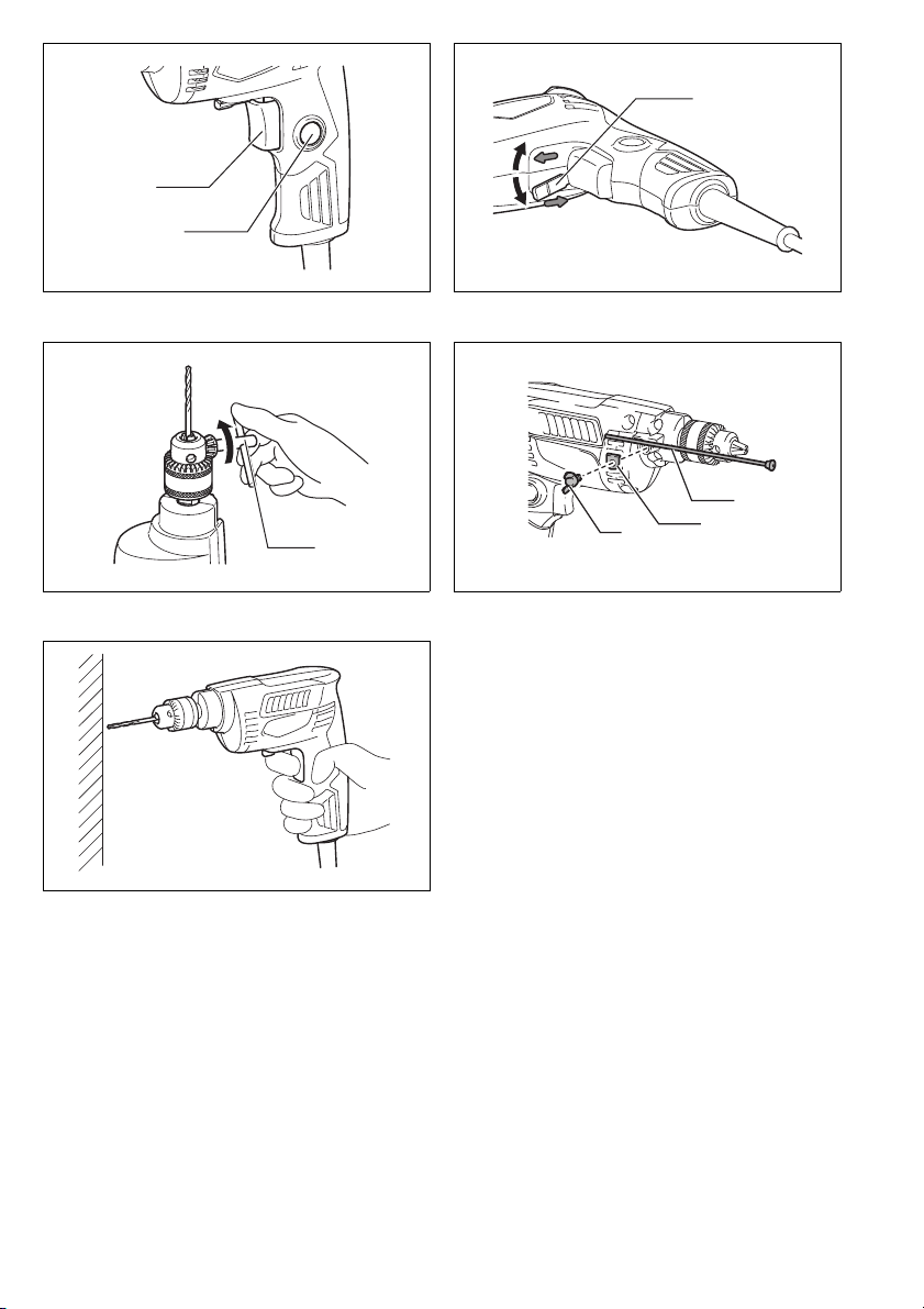
1 Switch trigger
2 Lock button
3 Reversing switch lever
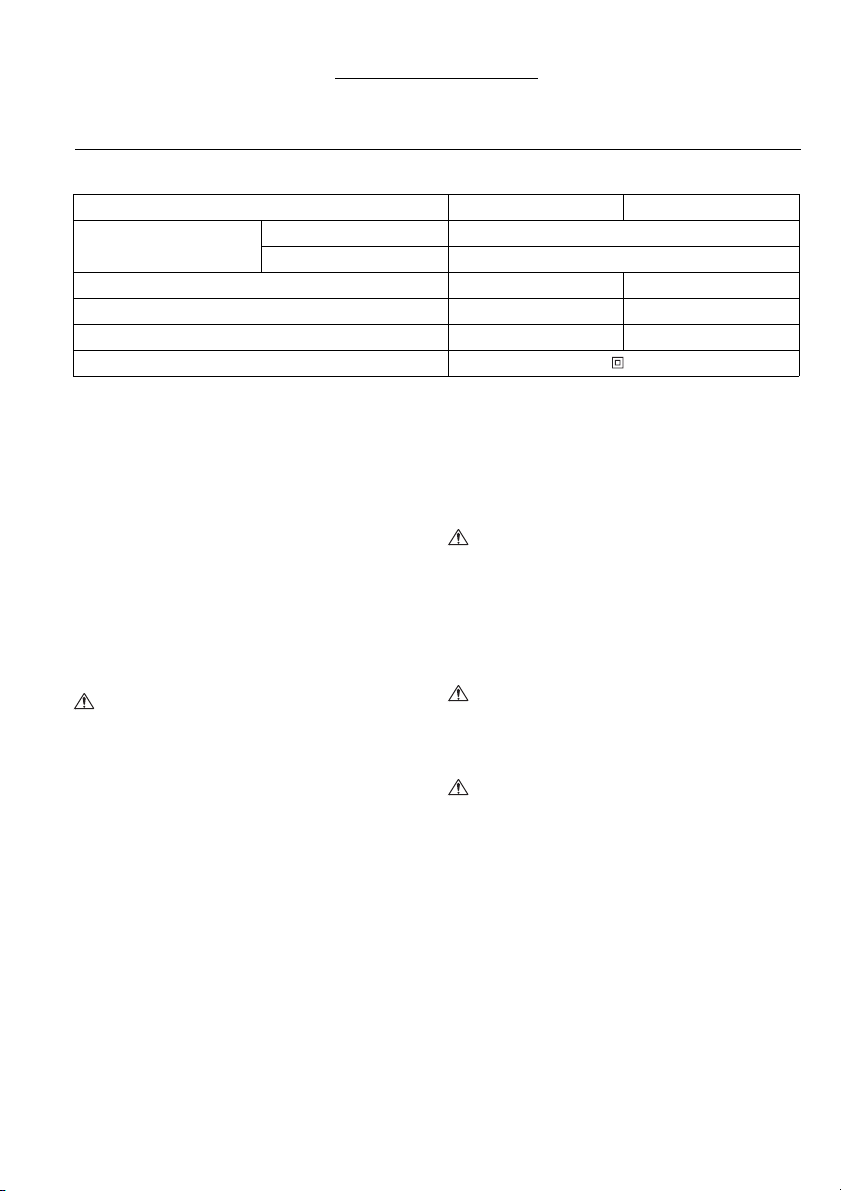
SPECIFICATIONS
Model M6500 M6501
Capacities
No load speed (min
Overall length 200 mm 203 mm
Net weight 0.92 kg 0.95 kg
Safety class /II
• Due to our continuing program of research and
development, the specifications herein are subject to
change without notice.
• Specifications may differ from country to country.
• Weight according to EPTA-Procedure 01/2003
Intended use
The tool is intended for drilling in wood, metal and plastic.
Power supply
The tool should be connected only to a power supply of
the same voltage as indicated on the nameplate, and can
only be operated on single-phase AC supply. They are
double-insulated and can, therefore, also be used from
sockets without earth wire.
General Power Tool Safety Warnings
WARNING Read all safety warnings and all
instructions. Failure to follow the warnings and
instructions may result in electric shock, fire and/or
serious injury.
Save all warnings and instructions for future
reference.
DRILL SAFETY WARNINGS
1. Use auxiliary handle(s), if supplied with the tool.
Loss of control can cause personal injury.
2. Hold power tool by insulated gripping surfaces,
when performing an operation where the cutting
accessory may contact hidden wiring or its own
cord. Cutting accessory contacting a “live” wire may
make exposed metal parts of the power tool “live”
and could give the operator an electric shock.
3. Always be sure you have a firm footing.
Be sure no one is below when using the tool in
high locations.
4. Hold the tool firmly.
5. Keep hands away from rotating parts.
6. Do not leave the tool running. Operate the tool
only when hand-held.
4 Chuck key
5 Depth gauge
6 Washer
Steel 6.5 mm
Wood 9 mm
–1
) 4,500 0 – 4,500
ENE032-1
ENF002-2
GEA010-1
GEB001-6
7 Clamp screw
7. Do not touch the drill bit or the workpiece
immediately after operation; they may be
extremely hot and could burn your skin.
8. Some material contains chemicals which may be
toxic. Take caution to prevent dust inhalation
and skin contact. Follow material supplier safety
data.
SAVE THESE INSTRUCTIONS.
WARNING:
DO NOT let comfort or familiarity with product
(gained from repeated use) replace strict adherence
to safety rules for the subject product. MISUSE or
failure to follow the safety rules stated in this
instruction manual may cause serious personal
injury.
FUNCTIONAL DESCRIPTION
CAUTION:
• Always be sure that the tool is switched off and
unplugged before adjusting or checking function on the
tool.
Switch action (Fig. 1)
CAUTION:
• Before plugging in the tool, always check to see the
switch trigger actuates properly and returns to the
“OFF” position when released.
• Switch can be locked in “ON” position for ease of
operator comfort during extended use. Apply caution
when locking tool in “ON” position and maintain firm
grasp on tool.
For Model M6500
To start the tool, simply pull the switch trigger. Release
the switch trigger to stop. For continuous operation, pull
the switch trigger, push in the lock button and then
release the switch trigger. To stop the tool from the
locked position, pull the switch trigger fully, then release
it.
3
Page 4

For Model M6501
To start the tool, simply pull the switch trigger. Tool speed
is increased by increasing pressure on the switch trigger.
Release the switch trigger to stop. For continuous
operation, pull the switch trigger, push in the lock button
and then release the switch trigger. To stop the tool from
the locked position, pull the switch trigger fully, then
release it.
Reversing switch action (Fig. 2)
For Model M6501
This tool has a reversing switch to change the direction
of rotation. Move the reversing switch lever to the D
position (A side) for clockwise rotation or to the E
position (B side) for counterclockwise rotation.
CAUTION:
• Always check the direction of rotation before operation.
• Use the reversing switch only after the tool comes to a
complete stop. Changing the direction of rotation
before the tool stops may damage the tool.
ASSEMBLY
CAUTION:
• Always be sure that the tool is switched off and
unplugged before carrying out any work on the tool.
Installing or removing drill bit (Fig. 3)
CAUTION:
• Always be sure that the tool is switched off and
unplugged before installing or removing the bit.
To install the bit, place it in the chuck as far as it will go.
Tighten the chuck by hand. Place the chuck key in each
of the three holes and tighten clockwise. Be sure to
tighten all three chuck holes evenly.
To remove the bit, turn the chuck key counterclockwise in
just one hole, then loosen the chuck by hand.
Depth gauge (Fig. 4)
For tool with depth gauge
Install the depth gauge on the tool with the clamp screw
and washer. Adjust the depth gauge to the desired depth
and tighten the clamp screw.
OPERATION (Fig. 5)
CAUTION:
• Always hold the tool only by the handle when
performing an operation. Do not touch the metal part.
Drilling operation
Drilling in wood
When drilling in wood, the best results are obtained with
wood drills equipped with a guide screw. The guide
screw makes drilling easier by pulling the bit into the
workpiece.
Drilling in metal
To prevent the bit from slipping when starting a hole,
make an indentation with a center-punch and hammer at
the point to be drilled. Place the point of the bit in the
indentation and start drilling.
Use a cutting lubricant when drilling metals. The
exceptions are iron and brass which should be drilled dry.
CAUTION:
• Pressing excessively on the tool will not speed up the
drilling. In fact, this excessive pressure will only serve
to damage the tip of your bit, decrease the tool
performance and shorten the service life of the tool.
• There is a tremendous force exerted on the tool/bit at
the time of hole break through. Hold the tool firmly and
exert care when the bit begins to break through the
workpiece.
• Always secure small workpieces in a vise or similar
hold-down device.
MAINTENANCE
CAUTION:
• Always be sure that the tool is switched off and
unplugged before carrying out any work on the tool.
• Never use gasoline, benzine, thinner, alcohol or the
like. Discoloration, deformation or cracks may result.
To maintain product SAFETY and RELIABILITY, repairs,
any other maintenance or adjustment should be
performed by Makita Authorized Service Centers, always
using Makita replacement parts.
Noise
The typical A-weighted noise level determined according
to EN60745:
Model M6500
Sound pressure level (L
Uncertainty (K): 3 dB (A)
The noise level under working may exceed 80 dB (A).
Model M6501
Sound pressure level (L
Uncertainty (K): 3 dB (A)
): 72 dB (A)
pA
): 70 dB (A)
pA
The noise level under working may exceed 80 dB (A).
Wear ear protection
Vibration
The vibration total value (tri-axial vector sum) determined
according to EN60745:
Model M6500
Work mode: drilling into metal
Vibration emission (a
Uncertainty (K): 1.5 m/s
h, D
): 2.5 m/s
2
2
Model M6501
Work mode: drilling into metal
Vibration emission (a
Uncertainty (K): 1.5 m/s
h, D
): 3.0 m/s
2
2
ENG905-1
ENG900-1
4
Page 5

• The declared vibration emission value has been
measured in accordance with the standard test method
and may be used for comparing one tool with another.
• The declared vibration emission value may also be
ENG901-1
used in a preliminary assessment of exposure.
WARNIN G:
• The vibration emission during actual use of the power
tool can differ from the declared emission value
depending on the ways in which the tool is used.
• Be sure to identify safety measures to protect the
operator that are based on an estimation of exposure in
the actual conditions of use (taking account of all parts
of the operating cycle such as the times when the tool
is switched off and when it is running idle in addition to
the trigger time).
ENH101-18
For European countries only
EC Declaration of Conformity
Makita declares that the following Machine(s):
Designation of Machine:
High Speed Drill
Model No./ Type: M6500, M6501
Conforms to the following European Directives:
2006/42/EC
They are manufactured in accordance with the following
Standard or standardized documents:
EN60745
The technical file in accordance with 2006/42/EC is
available from:
Makita, Jan-Baptist Vinkstraat 2, 3070, Belgium
1.12.2014
Yasushi Fukaya
Makita, Jan-Baptist Vinkstraat 2, 3070, Belgium
Director
5
Page 6

FRANÇAIS (Instructions originales)
Descriptif
1 Gâchette
2 Bouton de verrouillage
3 Levier de l’inverseur
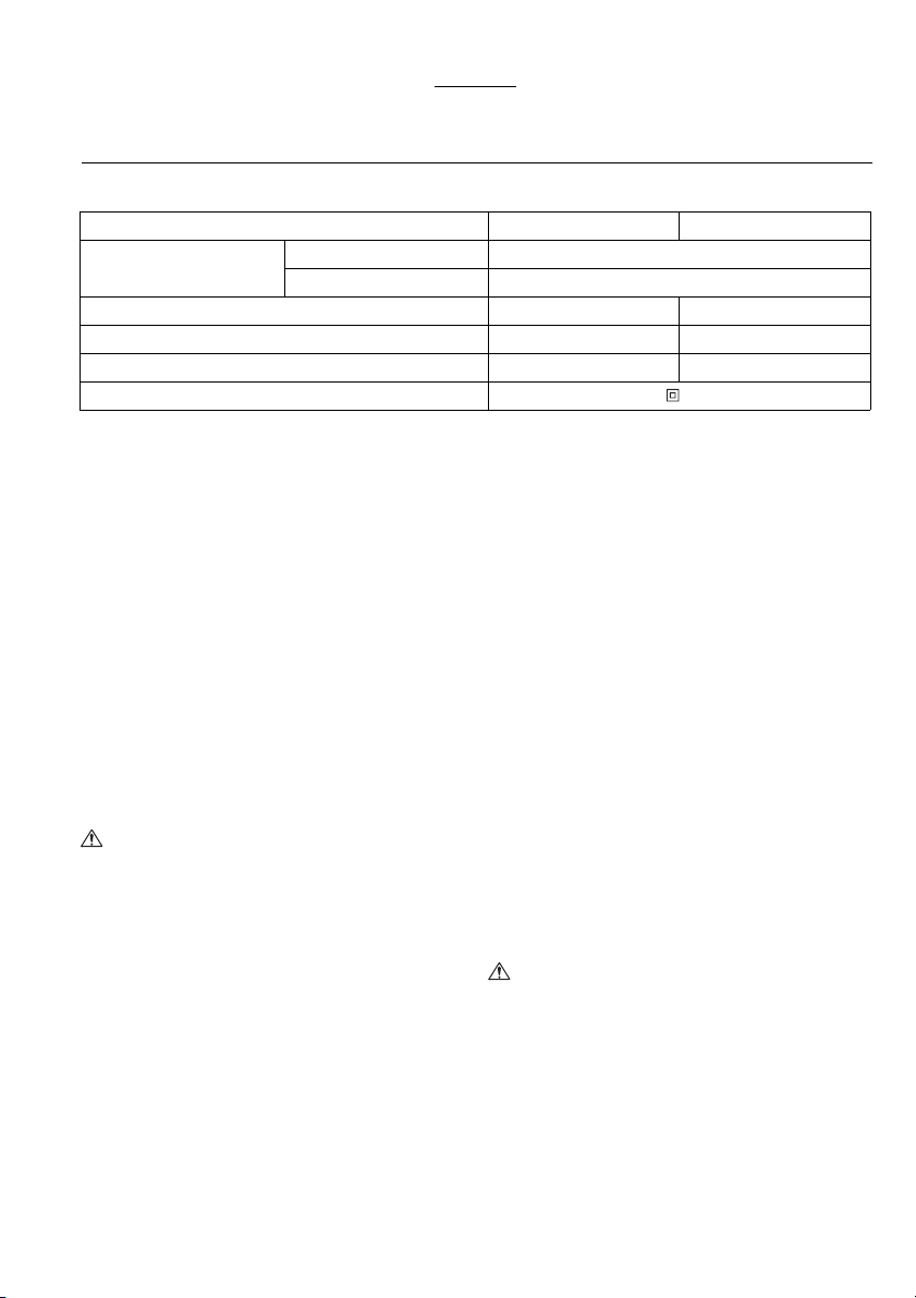
SPÉCIFICATIONS
Modèle M6500 M6501
Capacités
Vitesse à vide (min
Longueur totale 200 mm 203 mm
Poids net 0,92 kg 0,95 kg
Catégorie de sécurité /II
• Étant donné l’évolution constante de notre programme
de recherche et développement, les spécifications
contenues dans ce manuel sont sujettes à modification
sans préavis.
• Les spécifications peuvent varier suivant les pays.
• Poids selon la procédure EPTA 01/2003
Utilisations
L’outil est conçu pour percer dans le bois, le métal et le
plastique.
Alimentation
L’outil ne devra être raccordé qu’à une alimentation de la
même tension que celle qui figure sur la plaque
signalétique, et il ne pourra fonctionner que sur un
courant secteur monophasé. Réalisé avec une double
isolation, il peut de ce fait être alimenté sans mise à la
terre.
Consignes de sécurité générales pour outils
électriques
AVERTISSEMENT Veuillez lire toutes les mises
en garde et toutes les instructions. Il y a risque de
choc électrique, d’incendie et/ou de blessure grave si les
mises en garde et les instructions ne sont pas
respectées.
Conservez toutes les mises en garde et instructions
pour référence ultérieure.
CONSIGNES DE SÉCURITÉ POUR PERCEUSE
1. Utilisez la ou les poignée(s) auxiliaire(s), si l’outil
en possède. Toute perte de maîtrise de l’outil
comporte un risque de blessure.
4 Clé de mandrin
5 Jauge de profondeur
6 Rondelle
Acier 6,5 mm
Bois 9 mm
–1
) 4 500 0 – 4 500
ENE032-1
ENF002-2
GEA010-1
GEB001-6
7 Vis de serrage
2. Saisissez l’outil électrique uniquement par ses
surfaces de poigne isolées lorsque vous
effectuez des travaux au cours desquels
l’accessoire tranchant peut entrer en contact
avec des fils cachés ou avec le cordon
d’alimentation de l’outil. Le contact de l’accessoire
tranchant avec un fil sous tension peut également
mettre sous tension les parties métalliques
exposées de l’outil électrique, causant ainsi un choc
électrique chez l’utilisateur.
3. Assurez-vous toujours de travailler en position
stable.
Lorsque vous utilisez l’outil dans un endroit
élevé, assurez-vous qu’il n’y a personne en bas.
4. Tenez l’outil fermement.
5. Gardez les mains éloignées des pièces en
rotation.
6. Ne vous éloignez pas en laissant l’outil tourner.
Ne le faites fonctionner que lorsque vous l’avez
bien en main.
7. Ne touchez pas l’embout de perçage ou la pièce
immédiatement après l’exécution du travail ; ils
peuvent être extrêmement chauds et vous brûler
la peau.
8. Certains matériaux contiennent des produits
chimiques qui peuvent être toxiques. Prenez les
précautions nécessaires pour éviter que la
poussière dégagée lors du travail ne soit inhalée
ou n’entre en contact avec la peau. Suivez les
consignes de sécurité du fournisseur du
matériau.
CONSERVEZ CES INSTRUCTIONS.
AVERTISSEMENT :
NE vous laissez PAS tromper (au fil d’une utilisation
répétée) par un sentiment d’aisance et de familiarité
avec le produit, en négligeant le respect rigoureux
des consignes de sécurité qui accompagnent le
produit en question. La MAUVAISE UTILISATION de
l’outil ou l’ignorance des consignes de sécurité
indiquées dans ce manuel d’instructions peut
entraîner une blessure grave.
6
Page 7

DESCRIPTION DU FONCTIONNEMENT
ATTENTION :
• Assurez-vous toujours que l’outil est hors tension et
débranché avant de l’ajuster ou de vérifier son
fonctionnement.
Interrupteur (Fig. 1)
ATTENTION :
• Avant de brancher l’outil, vérifiez toujours que la
gâchette fonctionne correctement et qu’elle revient sur
la position “OFF” une fois relâchée.
• Vous pouvez verrouiller l’interrupteur sur la position
“ON” pour plus de confort en cas d’utilisation
prolongée. Soyez prudent lorsque vous verrouillez
l’outil sur la position “ON”, et gardez une prise ferme
sur l’outil.
Pour le modèle M6500
Pour mettre l’outil en marche, tirez simplement sur la
gâchette. Pour arrêter l’outil, libérez la gâchette. Pour un
fonctionnement continu, tirez sur la gâchette, enfoncez le
bouton de verrouillage puis relâchez la gâchette. Pour
arrêter l’outil lorsqu’il fonctionne en continu, tirez à fond
sur la gâchette puis relâchez-la.
Pour le modèle M6501
Pour mettre l’outil en marche, tirez simplement sur la
gâchette. La vitesse de l’outil augmente quand vous
augmentez la pression sur la gâchette. Pour arrêter
l’outil, libérez la gâchette. Pour un fonctionnement
continu, tirez sur la gâchette, enfoncez le bouton de
verrouillage puis relâchez la gâchette. Pour arrêter l’outil
lorsqu’il fonctionne en continu, tirez à fond sur la
gâchette puis relâchez-la.
Fonctionnement de l’inverseur (Fig. 2)
Pour le modèle M6501
Cet outil possède un inverseur qui permet de changer le
sens de la rotation. Déplacez le levier d’inverseur jusqu’à
la position D (côté A) pour une rotation dans le sens
des aiguilles d’une montre, ou jusqu’à la position E
(côté B) pour une rotation dans le sens contraire des
aiguilles d’une montre.
ATTENTION :
• Vérifiez toujours le sens de la rotation avant de
commencer le travail.
• N’activez l’inverseur qu’une fois l’outil parfaitement
arrêté. Vous risqueriez d’abîmer l’outil en changeant le
sens de rotation avant l’arrêt complet.
ASSEMBLAGE
ATTENTION :
• Avant d’effectuer toute intervention sur l’outil, assurezvous toujours qu’il est hors tension et débranché.
Pose ou retrait de l’embout de perçage (Fig. 3)
ATTENTION :
• Avant de poser ou de retirer l’embout, assurez-vous
toujours que l’outil est arrêté et débranché.
Pour poser l’embout, insérez-le à fond dans le mandrin.
Serrez le mandrin à la main. Mettez la clé de mandrin
dans chacun des trois orifices et tournez dans le sens
des aiguilles d’une montre. Vous devez serrer les trois
orifices de mandrin de manière égale.
Pour retirer l’embout, tournez la clé de mandrin dans le
sens contraire des aiguilles d’une montre dans un seul
des orifices, puis desserrez le mandrin à la main.
Jauge de profondeur (Fig. 4)
Pour outil avec jauge de profondeur
Installez la jauge de profondeur sur l’outil à l’aide de la
vis de serrage et de la rondelle. Réglez la jauge de
profondeur sur la profondeur désirée, puis serrez la vis
de serrage.
UTILISATION (Fig. 5)
ATTENTION :
• Lorsque vous travaillez avec l’outil, tenez-le toujours
uniquement par sa poignée. Ne touchez pas la partie
métallique.
Perçage
Perçage dans le bois
Lorsque vous percez dans le bois, vous obtiendrez un
résultat optimal avec un foret à bois équipé d’une vis de
guidage. La vis-guide rend le perçage plus aisé en tirant
le foret à l’intérieur de la pièce.
Perçage dans le métal
Pour que l’embout ne glisse pas quand vous commencez
à percer un trou, faites une entaille à l’aide d’un pointeau
et d’un marteau à l’emplacement prévu pour le trou.
Placez la pointe de l’embout dans l’entaille et
commencez à percer.
Utilisez un lubrifiant de coupe pour percer les métaux.
Seuls le fer et le laiton doivent être percés à sec.
ATTENTION :
• Une pression excessive sur l’outil n’accélèrera pas le
perçage. En fait, la pression excessive abîmera la
pointe de l’embout, causera une baisse de rendement
de l’outil et réduira sa durée de service.
• Une très grande force s’exerce sur l’outil et l’embout
lorsque celui-ci émerge sur la face opposée. Tenez
l’outil fermement et faites bien attention dès que le foret
commence à approcher de la face opposée de la
pièce.
• Assurez toujours les petites pièces à l’aide d’un étau
ou d’un dispositif de fixation similaire.
ENTRETIEN
ATTENTION :
• Avant d’effectuer toute intervention sur l’outil, assurezvous toujours qu’il est hors tension et débranché.
• N’utilisez jamais d’essence, benzine, diluant, alcool ou
autre produit similaire. Cela risquerait de provoquer la
décoloration, la déformation ou la fissuration de l’outil.
Pour maintenir la SÉCURITÉ et la FIABILITÉ du produit,
les réparations, travaux d’entretien et autres réglages
doivent être effectués dans un centre de service Makita
agréé, exclusivement avec des pièces de rechange
Makita.
7
Page 8

Bruit
Niveau de bruit pondéré A typique, déterminé selon
EN60745 :
Modèle M6500
Niveau de pression sonore (L
Incertitude (K) : 3 dB (A)
Le niveau de bruit en fonctionnement peut dépasser
80 dB (A).
) : 72 dB (A)
pA
ENG905-1
Modèle M6501
Niveau de pression sonore (L
Incertitude (K) : 3 dB (A)
Le niveau de bruit en fonctionnement peut dépasser
) : 70 dB (A)
pA
80 dB (A).
Porter des protecteurs anti-bruit
Vibrations
Valeur totale de vibrations (somme de vecteur triaxial)
ENG900-1
déterminée selon EN60745 :
Modèle M6500
Mode de travail : perçage dans le métal
Émission de vibrations (a
Incertitude (K) : 1,5 m/s
h, D
2
) : 2,5 m/s
2
Modèle M6501
Mode de travail : perçage dans le métal
Émission de vibrations (a
Incertitude (K) : 1,5 m/s
• La valeur d’émission de vibrations déclarée a été
mesurée conformément à la méthode de test standard
et peut être utilisée pour comparer les outils entre eux.
• La valeur d’émission de vibrations déclarée peut aussi
être utilisée pour l’évaluation préliminaire de
h, D
2
) : 3,0 m/s
2
ENG901-1
l’exposition.
AVERTISSEMENT :
• L’émission de vibrations lors de l’usage réel de l’outil
électrique peut être différente de la valeur d’émission
déclarée, suivant la façon dont l’outil est utilisé.
• Les mesures de sécurité à prendre pour protéger
l’utilisateur doivent être basées sur une estimation de
l’exposition dans des conditions réelles d’utilisation (en
tenant compte de toutes les composantes du cycle
d’utilisation, comme par exemple le moment de sa
mise hors tension, lorsqu’il tourne à vide et le moment
de son déclenchement).
Pour les pays d’Europe uniquement
ENH101-18
Déclaration de conformité CE
Makita déclare que la (les) machine(s) suivante(s) :
Désignation de la machine :
Perceuse à Haute Vitesse
N° de modèle / Type : M6500, M6501
sont conformes aux Directives européennes
suivantes :
2006/42/CE
et sont fabriquées conformément aux normes ou aux
documents normalisés suivants :
EN60745
La documentation technique conforme à la norme 2006/
42/CE est disponible auprès de :
Makita, Jan-Baptist Vinkstraat 2, 3070, Belgique
1.12.2014
Yasushi Fukaya
Makita, Jan-Baptist Vinkstraat 2, 3070, Belgique
Directeur
8
Page 9
DEUTSCH (Originale Anleitungen)
Übersicht
1 Elektronikschalter
2 Arretierknopf
3 Drehrichtungsumschalter
TECHNISCHE DATEN
Modell M6500 M6501
Kapazitäten
Leerlaufdrehzahl (min
Gesamtlänge 200 mm 203 mm
Nettogewicht 0,92 kg 0,95 kg
Sicherheitsklasse /II
• Aufgrund unseres Dauerprogramms der Forschung
und Entwicklung unterliegen die hier angegebenen
technischen Daten Änderung ohne Vorankündigung.
• Die technischen Daten können von Land zu Land
abweichen.
• Gewicht nach EPTA-Verfahren 01/2003
Vorgesehene Verwendung
Die Maschine ist für Bohren in Holz, Metall und
Kunststoff vorgesehen.
Netzanschluss
Die Maschine sollte nur an eine Stromquelle
angeschlossen werden, deren Spannung mit der Angabe
auf dem Typenschild übereinstimmt, und kann nur mit
Einphasen-Wechselstrom betrieben werden. Diese sind
doppelt schutzisoliert und können daher auch an
Steckdosen ohne Erdleiter verwendet werden.
Allgemeine Sicherheitswarnungen für
Elektrowerkzeuge
WARNUNG Lesen Sie alle Sicherheitswarnungen
und Anweisungen durch. Eine Missachtung der unten
aufgeführten Warnungen und Anweisungen kann zu
einem elektrischen Schlag, Brand und/oder schweren
Verletzungen führen.
Bewahren Sie alle Warnungen und Anweisungen für
spätere Bezugnahme auf.
SICHERHEITSWARNUNGEN FÜR BOHRER
1. Benutzen Sie (einen) Zusatzgriff(e), sofern er
(sie) mit dem Werkzeug geliefert wurde(n).
Verlust der Kontrolle kann Verletzungen
verursachen.
4Futterschlüssel
5 Tiefenanschlag
6 Unterlegscheibe
Stahl 6,5 mm
Holz 9 mm
–1
) 4 500 0 – 4 500
ENE032-1
ENF002-2
GEA010-1
GEB001-6
7 Klemmschraube
2. Halten Sie das Elektrowerkzeug nur an den
isolierten Griffflächen, wenn Sie Arbeiten
ausführen, bei denen die Gefahr besteht, dass
verborgene Kabel oder das eigene Kabel
kontaktiert werden. Bei Kontakt mit einem Strom
führenden Kabel können die freiliegenden
Metallteile des Elektrowerkzeugs ebenfalls Strom
führend werden, so dass der Benutzer einen
elektrischen Schlag erleiden kann.
3. Achten Sie stets auf sicheren Stand.
Vergewissern Sie sich bei Einsatz der Maschine
an hochgelegenen Arbeitsplätzen, dass sich
keine Personen darunter aufhalten.
4. Halten Sie die Maschine mit festem Griff.
5. Halten Sie die Hände von rotierenden Teilen fern.
6. Lassen Sie die Maschine nicht unbeaufsichtigt
laufen. Benutzen Sie die Maschine nur mit
Handhaltung.
7. Vermeiden Sie eine Berührung des
Bohrereinsatzes oder des Werkstücks
unmittelbar nach der Bearbeitung, weil die Teile
noch sehr heiß sind und Hautverbrennungen
verursachen können.
8. Manche Materialien können giftige Chemikalien
enthalten. Treffen Sie Vorsichtsmaßnahmen, um
das Einatmen von Arbeitsstaub und Hautkontakt
zu verhüten. Befolgen Sie die Sicherheitsdaten
des Materialherstellers.
BEWAHREN SIE DIESE HINWEISE
SORGFÄLTIG AUF.
WARNUNG:
Lassen Sie sich NICHT durch Bequemlichkeit oder
Vertrautheit mit dem Produkt (durch wiederholten
Gebrauch erworben) von der strikten Einhaltung der
Sicherheitsregeln für das vorliegende Produkt
abhalten. MISSBRAUCH oder Missachtung der
Sicherheitsvorschriften in dieser Anleitung können
schwere Verletzungen verursachen.
9
Page 10

FUNKTIONSBESCHREIBUNG
VORSICHT:
• Vergewissern Sie sich vor jeder Einstellung oder
Funktionsprüfung der Maschine stets, dass sie
ausgeschaltet und vom Stromnetz getrennt ist.
Schalterfunktion (Abb. 1)
VORSICHT:
• Vergewissern Sie sich vor dem Anschließen der
Maschine an das Stromnetz stets, dass der
Elektronikschalter ordnungsgemäß funktioniert und
beim Loslassen in die “AUS” Stellung zurückkehrt.
• Der Schalter kann zur Arbeitserleichterung bei
längerem Einsatz in der “EIN” Stellung verriegelt
werden. Lassen Sie Vorsicht walten, wenn Sie den
Schalter in der “EIN” Stellung verriegeln, und halten Sie
die Maschine mit festem Griff.
Für Modell M6500
Zum Einschalten der Maschine einfach den
Elektronikschalter drücken. Zum Ausschalten den
Elektronikschalter loslassen. Für Dauerbetrieb den
Elektronikschalter betätigen, den Arretierknopf
hineindrücken, und dann den Elektronikschalter
loslassen. Zum Ausrasten der Sperre den
Elektronikschalter bis zum Anschlag hineindrücken und
dann loslassen.
Für Modell M6501
Zum Einschalten der Maschine einfach den
Elektronikschalter drücken. Die Drehzahl erhöht sich
durch verstärkte Druckausübung auf den
Elektronikschalter. Zum Ausschalten den
Elektronikschalter loslassen. Für Dauerbetrieb den
Elektronikschalter betätigen, den Arretierknopf
hineindrücken, und dann den Elektronikschalter
loslassen. Zum Ausrasten der Sperre den
Elektronikschalter bis zum Anschlag hineindrücken und
dann loslassen.
Funktion des Drehrichtungsumschalters (Abb. 2)
Für Modell M6501
Diese Maschine besitzt einen Drehrichtungsumschalter.
Stellen Sie den Drehrichtungsumschalter für
Rechtsdrehung auf die Stellung D (Seite A) bzw. für
Linksdrehung auf die Stellung E (Seite B).
VORSICHT:
• Prüfen Sie stets die Drehrichtung, bevor Sie mit der
Arbeit beginnen.
• Betätigen Sie den Drehrichtungsumschalter erst,
nachdem die Maschine völlig zum Stillstand gekommen
ist. Durch Umschalten der Drehrichtung bei noch
laufender Maschine kann die Maschine beschädigt
werden.
MONTAGE
VORSICHT:
• Vergewissern Sie sich vor der Ausführung von Arbeiten
an der Maschine stets, dass sie ausgeschaltet und vom
Stromnetz getrennt ist.
Montage und Demontage des Bohrereinsatzes
(Abb. 3)
VORSICHT:
• Vergewissern Sie sich vor der Montage oder
Demontage des Einsatzes stets, dass die Maschine
ausgeschaltet und vom Stromnetz getrennt ist.
Den Bohrereinsatz zum Montieren bis zum Anschlag in
das Futter einführen. Das Futter von Hand anziehen.
Den Futterschlüssel in jedes der drei Löcher einsetzen
und im Uhrzeigersinn drehen. Das Futter in allen drei
Löchern mit gleicher Kraft anziehen.
Den Futterschlüssel zum Demontieren des
Bohrereinsatzes nur in ein Loch einführen und entgegen
dem Uhrzeigersinn drehen, bevor das Futter von Hand
gelöst wird.
Tiefenanschlag (Abb. 4)
Für Maschine mit Tiefenanschlag
Bringen Sie den Tiefenanschlag mit der Klemmschraube
und Unterlegscheibe an der Maschine an. Stellen Sie
den Tiefenanschlag auf die gewünschte Bohrtiefe ein,
und ziehen Sie die Klemmschraube an.
BETRIEB (Abb. 5)
VORSICHT:
• Halten Sie das Werkzeug bei der Arbeit immer nur am
Handgriff. Berühren Sie nicht den Metallteil.
Bohrbetrieb
Bohren in Holz
Beim Bohren in Holz lassen sich die besten Ergebnisse
mit Holzbohrern erzielen, die mit einer Zentrierspitze
ausgestattet sind. Die Zentrierspitze erleichtert das
Bohren, da sie den Bohrer in das Werkstück hineinzieht.
Bohren in Metall
Um Abrutschen des Bohrers beim Anbohren zu
vermeiden, empfiehlt es sich, die Bohrstelle mit einem
Zentrierkörner anzukörnen. Setzen Sie dann die Spitze
des Bohrers in die Vertiefung, und beginnen Sie mit dem
Bohren.
Verwenden Sie Schneidflüssigkeit beim Bohren von
Metall. Eisen und Messing sollten jedoch trocken gebohrt
werden.
VORSICHT:
• Übermäßige Druckausübung auf die Maschine bewirkt
keine Beschleunigung der Bohrleistung. Im Gegenteil;
übermäßiger Druck führt zu einer Beschädigung der
Bohrerspitze und damit zu einer Verringerung der
Leistungsfähigkeit sowie zu einer Verkürzung der
Lebensdauer der Maschine.
• Beim Bohrungsdurchbruch wirkt ein hohes
Rückdrehmoment auf Maschine und Bohrer. Halten Sie
daher die Maschine mit festem Griff und lassen Sie
Vorsicht walten, wenn der Bohrer im Begriff ist, aus
dem Werkstück auszutreten.
• Kleine Werkstücke sind stets in einen Schraubstock
oder eine ähnliche Aufspannvorrichtung einzuspannen.
WARTUNG
VORSICHT:
• Vergewissern Sie sich vor der Ausführung von Arbeiten
an der Maschine stets, dass sie ausgeschaltet und vom
Stromnetz getrennt ist.
• Verwenden Sie auf keinen Fall Benzin, Benzol,
Verdünner, Alkohol oder dergleichen. Solche Mittel
können Verfärbung, Verformung oder Rissbildung
verursachen.
10
Page 11

Um die SICHERHEIT und ZUVERLÄSSIGKEIT dieses
Produkts zu gewährleisten, sollten Reparaturen und
andere Wartungs- oder Einstellarbeiten nur von MakitaKundendienstzentren unter ausschließlicher
Verwendung von Makita-Originalersatzteilen ausgeführt
werden.
Geräusch
Typischer A-bewerteter Geräuschpegel ermittelt gemäß
ENG905-1
EN60745:
Modell M6500
Schalldruckpegel (L
Ungewissheit (K): 3 dB (A)
Der Lärmpegel kann während des Betriebs 80 dB (A)
überschreiten.
Modell M6501
Schalldruckpegel (L
Ungewissheit (K): 3 dB (A)
Der Lärmpegel kann während des Betriebs 80 dB (A)
überschreiten.
): 72 dB (A)
pA
): 70 dB (A)
pA
Gehörschutz tragen
Vibration
ENG900-1
Vibrationsgesamtwert (Drei-Achsen-Vektorsumme)
ermittelt gemäß EN60745:
Modell M6500
Arbeitsmodus: Bohren in Metall
Vibrationsemission (a
Ungewissheit (K): 1,5 m/s
Modell M6501
Arbeitsmodus: Bohren in Metall
Vibrationsemission (a
Ungewissheit (K): 1,5 m/s
h, D
h, D
• Der angegebene Vibrationsemissionswert wurde im
Einklang mit der Standardprüfmethode gemessen und
kann für den Vergleich zwischen Maschinen
herangezogen werden.
• Der angegebene Vibrationsemissionswert kann auch
für eine Vorbewertung des Gefährdungsgrads
verwendet werden.
WARNUNG:
• Die Vibrationsemission während der tatsächlichen
Benutzung des Elektrowerkzeugs kann je nach der
Benutzungsweise der Maschine vom angegebenen
Emissionswert abweichen.
• Identifizieren Sie Sicherheitsmaßnahmen zum Schutz
des Benutzers anhand einer Schätzung des
Gefährdungsgrads unter den tatsächlichen
Benutzungsbedingungen (unter Berücksichtigung aller
Phasen des Arbeitszyklus, wie z. B. Ausschalt- und
Leerlaufzeiten der Maschine zusätzlich zur
Betriebszeit).
): 2,5 m/s
2
): 3,0 m/s
2
2
2
ENG901-1
Nur für europäische Länder
ENH101-18
EG-Übereinstimmungserklärung
Makita erklärt, dass die folgende(n) Maschine(n):
Bezeichnung der Maschine:
Hochgeschwindigkeits-Bohrmaschine
Modell-Nr./ Typ: M6500, M6501
den folgenden europäischen Richtlinien entsprechen:
2006/42/EG
gemäß den folgenden Standards oder standardisierten
Dokumenten hergestellt werden:
EN60745
Die technische Akte in Übereinstimmung mit 2006/42/EG
ist erhältlich von:
Makita, Jan-Baptist Vinkstraat 2, 3070, Belgien
1.12.2014
Yasushi Fukaya
Makita, Jan-Baptist Vinkstraat 2, 3070, Belgien
Direktor
11
 Loading...