

Page 1
T
Description
ECHNICAL INFORMATION
Model No.
6411, 6412, 6413, M611
Drill 10mm (3/8")
PRODUCT
P 1 /12
L
L
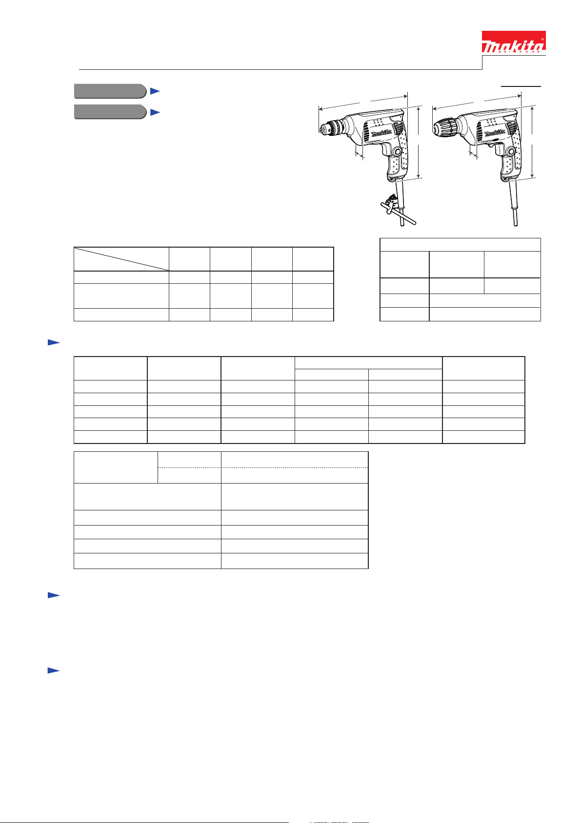
CONCEPT AND MAIN APPLICATIONS
Models 6411, 6412, 6413 and M611 are cost-competitive
10mm Drills developed as the successor models of
6409, 6410, 6510SB and M610, featuring compact and
lightweight design yet with high durability.
Listed below are the specification differences among
the four models.
Model No.
Specification
Reverse switch
Variable speed control
by trigger
Drill chuck type
Specification
Voltage (V) Cycle (Hz)
110 4.3 450 230 35050/ 60
120
220
230
240
6411
No
No
Current (A)
4.0 --- 230 35050/ 60
2.2 450 230 35050/ 60
2.1 450 230 35050/ 60
2.0 450 230 35050/ 60
6412 6413
Yes Yes
Yes
KeyedKeyed
Yes
Keyless
W
6411, 6412
M611
M611
Yes
Yes
Keyed
Continuous Rating (W)
Input Output
H
Model
Length (L)
Width (W)
Height (H)
W
6413
Dimensions: mm (")
6411, 6412
M611
228 (9)
Max. Output (W)
234 (9-1/4)
64 (2-1/2)
183 (7-1/4)
H
6413
Capacities: mm (")
Steel
Wood
No load speed: min-1=rpm
Chuck capacity: mm (")
Double insulation
Power supply cord: m (ft)
Net weight: kg (lbs)
6412, 6413, M611: 0 -3,000
10 (3/8)
25 (1)
6411: 3,000
1.5 - 10 (1/16 -3/8)
Yes
2.0 (6.6)
1.2 (2.6)
Standard equipment
Chuck key S10 ............ 1 (for 6411, 6412, M611)
Key holder 10 .............. 1 (for 6411, 6412, M611)
Note: The standard equipment for the tool shown above may differ by country.
Optional accessories
Drills bits
Page 2
Repair
CAUTION: Unplug the machine for safety before repair/ maintenance
in accordance with the instruction manual!
[1] NECESSARY REPAIRING TOOLS
DescriptionCode No. Use for
1R004 Removing/Installing Ring spring 13 from Spindle
1R139
1R220
1R222 Socket adapter
1R223
A-33750
1R231
1R269
1R273
1R031
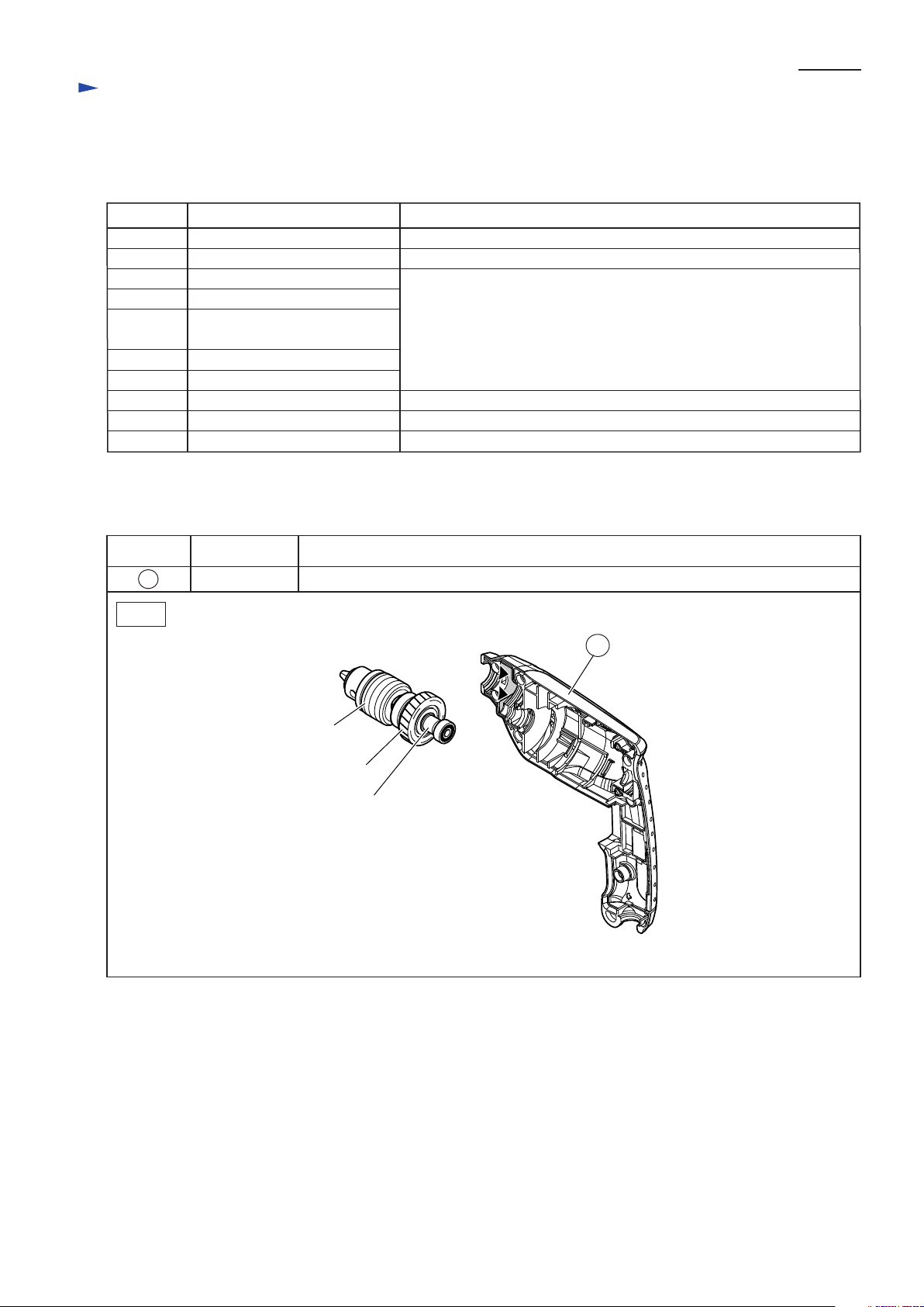
[2] LUBRICATION
Apply Makita grease N. No.1 to the following portions designated with the black triangle to protect
parts and product from unusual abrasion.
Retaining ring pliers ST-2
Drill chuck extractor
Ratchet head 9.5
Torque wrench shaft 20- 90N.m
Bit Adaptor
1/4" Hex. shank bit for M8
Bearing extractor
Ring spring 26 setting tool B
Bearing setting pipe 28-20.2
Locking Spindle when removing Drill chuck from Spindle
Assembling Drill chuck to Spindle
Note: Preset the fastening torque of 1R223
to 25- 30 N.m (250- 300kgf.cm).
Removing Ball bearing 606ZZ
Removing/Installing Helical gear 35
Removing/Installing Ball bearing 6902ZZ
P 2 /12
Item No. Description Portion to lubricate
7
Fig. 1
Housing Gear room for Helical Gear 35 (Apply approx. 3g.)
7
Drill chuck S-10
Helical gear 35
Spindle
Page 3
P 3 /12
Repair
[3] DISASSEMBLY/ASSEMBLY
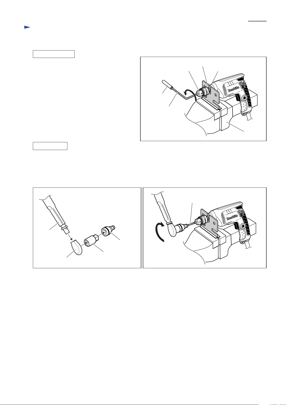
[3] -1. Drill Chuck
DISASSEMBLING
See Fig. 2.
1) Fix 1R139 securely in vise, then lock Spindle
by putting it in the U-shaped notch of 1R139.
2) Fix Hex wrench 10 securely in Drill chuck.
Attach an appropriate steel pipe to Hex wrench 10
as extension bar.
3) Remove Drill chuck from Spindle by turning
Drill chuck counterclockwise using Hex wrench 10
and steel pipe.
ASSEMBLING
1) Assemble 1R220, 1R222, 1R223 and A-33750 as illustrated in Fig. 3.
Note: Preset the fastening torque of 1R223 to 25- 30N.m (250- 300 kgf.cm).
2) Lock Spindle as you did in step 1) of DISASSEMBLING, then fix 1R231 securely in Drill chuck. (Fig. 4)
3) Assemble Drill chuck to Spindle by turning 1R231 and Drill chuck clockwise using the repairing tools described in
step 1) of ASSEMBLING. (Fig. 4)
Fig. 3 Fig. 4
Fig. 2
steel pipe
Hex wrench 10
Drill chuck
1R139
Spindle
Vise
1R223
1R231
A-33750
1R222
1R220
Page 4
Repair
[3] DISASSEMBLY/ASSEMBLY
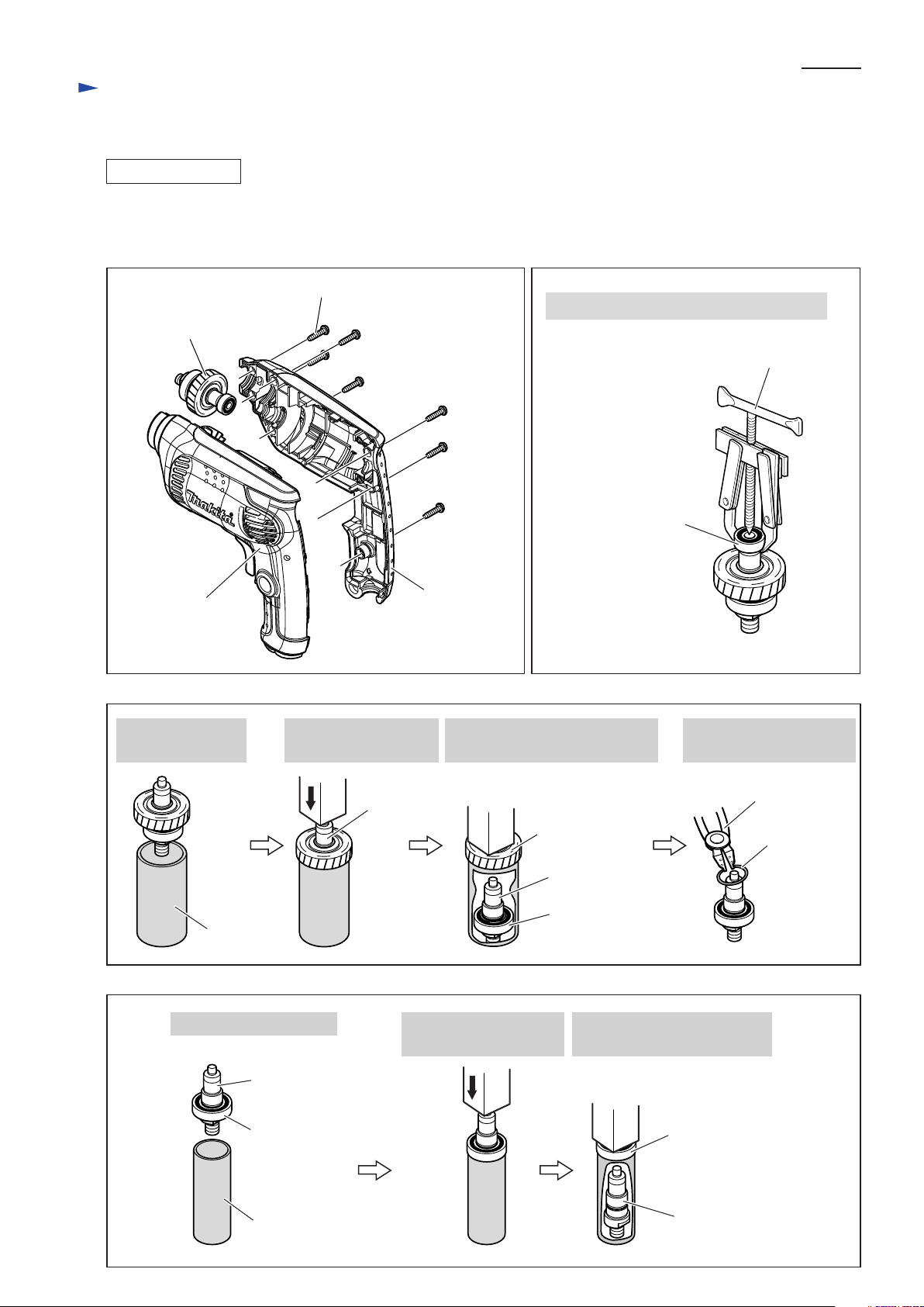
[3] -2. Gear Section
DISASSEMBLING
1) After disassembling Drill chuck as illustrated in Fig. 2, separate Housing (R) from Housing (L).
Remove Gear section from Housing (L). (Fig. 5)
2) Disassemble Gear section as illustrated in Figs. 6, 7, 8.
Fig. 5 Fig. 6
Tapping screw 4x18 (7 pcs)
1) Remove Ball bearing 606ZZ with 1R269.
Gear section
P 4 /12
1R269
Housing (L)
Fig. 7
2) Put Gear section
on 1R273.
1R273
3) By pressing Spindle
using arbor press,
Spindle
Ball bearing 606ZZ
Housing (R)
Spindle can be removed together
with Ball bearing 6902ZZ.
Helical gear 35
Spindle
Ball bearing
6902ZZ
4) Remove Ring spring 13
using 1R004.
1R004
Ring spring 13
Fig. 8
5) Put Spindle on 1R031. 6) By pressing Spindle
using arbor press,
Spindle
Ball bearing
6902ZZ
1R031
Spindle can be removed from
Ball bearing 6902ZZ.
Ball bearing
6902ZZ
Spindle
Page 5

Repair
[3] DISASSEMBLY/ASSEMBLY
[3] -2. Gear Section (cont.)
ASSEMBLING
1) Assemble Gear section as illustrated in Fig. 9 to Fig. 12.
2) Assemble Gear section to Housing (L). (Fig. 5 in page 4)
Fig. 9 Fig. 10
P 5/12
Fig. 11
Ball bearing
6902ZZ
1) Assemble Ball bearing to Spindle
using 1R031 and arbor press.
Spindle
Ball bearing 6902ZZ
1R031
3) Assemble Helical gear 35 to Spindle using 1R273
and arbor press.
Note:
Helical gear 35 is not reversible when assembled
to Spindle. The flat side of the gear must face
towards Ball bearing 6902ZZ.
flat side
Helical gear 35
grooved side
2) Fix Ball bearing 6902ZZ by assembling
Ring spring 13 to Spindle using 1R004.
Note:
If Ring spring 13 is deformed or damaged
when removed from Spindle, be sure to
replace it with new one.
Ring spring 13
Fig. 12
4) Assemble Ball bearing 606ZZ
to Spindle using arbor press.
Ball bearing 606ZZ
1R273
flat side
[3] -3. Motor Section
DISASSEMBLING
1) After separating Housing (R) from Housing (L), disconnect Carbon brushes from Armature commutator by pulling off
Brush holders from Housing (L). Disassemble Motor section from Housing (L). (Fig. 13)
2) Pull out Armature from Field. (Fig. 14)
Fig. 13 Fig. 14
Motor section
Brush holder
Carbon brush
Armature commutator
Leaf spring
Housing (L)
Carbon brush
Brush holder
Armature
Field
Page 6

Repair
[3] DISASSEMBLY/ASSEMBLY
[3] -3. Motor Section (cont.)
ASSEMBLING
Do the reverse of the disassembling steps.
Note:
Leaf spring is not reversible when assembled
to Housing (L). The concave side must face towards
Ball bearing 627ZZ on Armature. (Fig. 15)
P 6/12
Fig. 15
Housing (L)
Ball bearing 627ZZ
Leaf spring
concave side
Page 7

Circuit diagram
Model 6411 (without Variable speed control and Reverse switch)
Machines Without Choke Coil and Noise Suppressor
Fig. D-1
Color index of lead wires' sheath
Black
White
P 7/12
Brush holder
Field
Switch
Power supply cord
Page 8

Wiring diagram
Model 6411 (without Variable speed control and Reverse switch)
Machines Without Choke Coil
Important: Do not put slack portion of any Lead wire in the space surrounded by Field and Brush holders.
Otherwise Lead wires will be broken by rotating Armature.
Fig. D-2
P 8/12
Put slack portion of Field lead wire (black)
in the space between Brush holder and
inside wall of Housing (L).
boss A
boss B
See "Connecting Lead wire to Brush holder".
Route the following two Lead wires
between the ribs:
*Field lead wire (white)
*Lead wire (black)
from No.2a Terminal of Switch
to Brush holder
Power supply cord
See "Connecting Lead wire to Brush holder".
Brush holder
Field
Switch
Route Field lead wire (white)
under Brush holder.
Connecting Lead wire to Brush holder
1) Brush holders are not reversible
when assembled to Housing (L).
Terminal insertion hole of each
Brush holder must be positioned
outside boss A/boss B.
2) Do not route each Lead wire
inside boss A/boss B.
boss A
boss B
Field lead wire (black)
Terminal
Lead wire (black)
from No.2a Terminal of Switch
Brush holder
Page 9

Circuit diagram
Model 6411 (without Variable speed control and Reverse switch)
Machines With Choke Coil
Fig. D-3
P 9/12
Color index of lead wires' sheath
Black
White
Orange
Purple
Brush holder
*Note: Some countries do not use Noise suppressor.
Choke coil
(with purple Lead wires)
Field
Choke coil
(with orange Lead wires)
*Noise suppressor
[if used]
Switch
Power supply cord
Page 10

Wiring diagram
Model 6411 (without Variable speed control and Reverse switch)
Machines With Choke Coil
Important: Do not put slack portion of any Lead wire in the space surrounded by Field and Brush holders.
Otherwise Lead wires will be broken by rotating Armature.
Note: 1) Some countries do not use Noise suppressor.
2) Put Choke coils and Noise suppressor (if used) in place as illustrated in Fig. D-4.
Fig. D-4
Lead wires
Choke coil lead wire (purple) to Brush holder
Choke coil lead wire (purple) to No.1a Terminal of Switch
Choke coil lead wire (orange) to Brush holder
Choke coil lead wire (orange) to Field
Field lead wire (black) to No.2a Terminal of Switch
See "Connecting Lead wire to Brush holder".
Brush holder
Put slack portion of Lead wire
in the space between Brush holder
and inside wall of Housing (L).
Otherwise the Lead wire will touch
rotating Armature.
Fix two Lead wires
with this Lead wire holder.
Choke coil
(with purple Lead wires)
P 10/12
boss A
boss B
See "Connecting Lead wire to Brush holder".
Route Lead wires
between these ribs.
Choke coil
(with orange Lead wires)
Field
Switch
Route Lead wires
under Brush holder.
Noise suppressor
[if used]
Power supply cord
Connecting Lead wire to Brush holder
1) Brush holders are not reversible
when assembled to Housing (L).
Terminal insertion hole of each
Brush holder must be positioned
outside boss A/boss B.
2) Do not route each Lead wire
inside boss A/boss B.
boss A
boss B
Terminal
Brush holder
Page 11

Circuit diagram
Models 6412, 6413, M611 (with Variable speed control and Reverse switch)
Fig. D-5
Color index of lead wires' sheath
Black
White
Orange
Blue
Purple
Note:
*Choke coil (with blue Lead wire and black Lead wire)
is reversible when connected to Switch.
**Some countries do not use Noise suppressor or Choke coils.
*Choke coil
(with purple Lead wires)
[if used]
P 11/12
Brush holder
*Choke coil
(with orange Lead wires)
[if used]
*Choke coil
(with blue Lead wire
and black Lead wire)
[if used]
**Noise suppressor
[if used]
Field
Switch
Power supply cord
Page 12

Wiring diagram
Models 6412, 6413, M611 (with Variable speed control and Reverse switch)
Important: Do not put slack portion of any Lead wire in the space surrounded by Field and Brush holders.
Otherwise Lead wires will be broken by rotating Armature.
Note: 1) Some countries do not use Noise suppressor or Choke coils.
2) Put Choke coils and Noise suppressor (if used) in place as illustrated in Fig. D-6.
3) Choke coil (with blue Lead wire and black Lead wire) is reversible when connected to Switch.
Fig. D-6
Lead wires
Choke coil lead wire (purple) to Brush holder
Choke coil lead wire (purple) to No.4 Terminal of Switch
Choke coil lead wire (orange) to Brush holder
Choke coil lead wire (orange) to No.3 Terminal of Switch
Field lead wire (black) to No.2a Terminal of Switch
Field lead wire (white) to No.5 Terminal of Switch
Choke coil lead wire (blue or black) to No.6 Terminal of Switch
Brush holder
See "Connecting Lead wire to Brush holder".
Fix two Lead wires
with this Lead wire holder.
Choke coil
(with purple Lead wires)
[if used]
P 12/12
Put slack portion of Lead wire
in the space between Brush holder
and inside wall of Housing (L).
Otherwise the Lead wire will touch
rotating Armature.
Put slack portion of Lead wires
in this space.
See "Connecting Lead wire to Brush holder".
Route Lead wires
between these ribs.
Choke coil
(with orange Lead wires)
[if used]
Choke coil
(with blue Lead wire
and black Lead wire)
[if used]
boss A
boss B
Field
Switch
Route Lead wires
under Brush holder.
Noise suppressor
[if used]
Power supply cord
Connecting Lead wire to Brush holder
1) Brush holders are not reversible
when assembled to Housing (L).
Terminal insertion hole of each
Brush holder must be positioned
outside boss A/boss B.
2) Do not route each Lead wire
inside boss A/boss B.
boss A
boss B
Terminal
Brush holder
 Loading...